Embed Size (px)
Citation preview

Strip Module Working Group Meeting
16th May 2012
Hybrids
A Greenall

Outline
•ABCN-25 Shield-less hybrid •Changes being made•Current status
•Serial Powering of Modules•Latest results with “Chain of Modules” configuration for a single module
•ABC130•First pass at Pad ring•Iterative process between hybrid and asic designers – converging to a preferred geometry•See Francis’s talk...
•Irradiation of new family of NTCs•Prerequisite for use with HCC
1
2
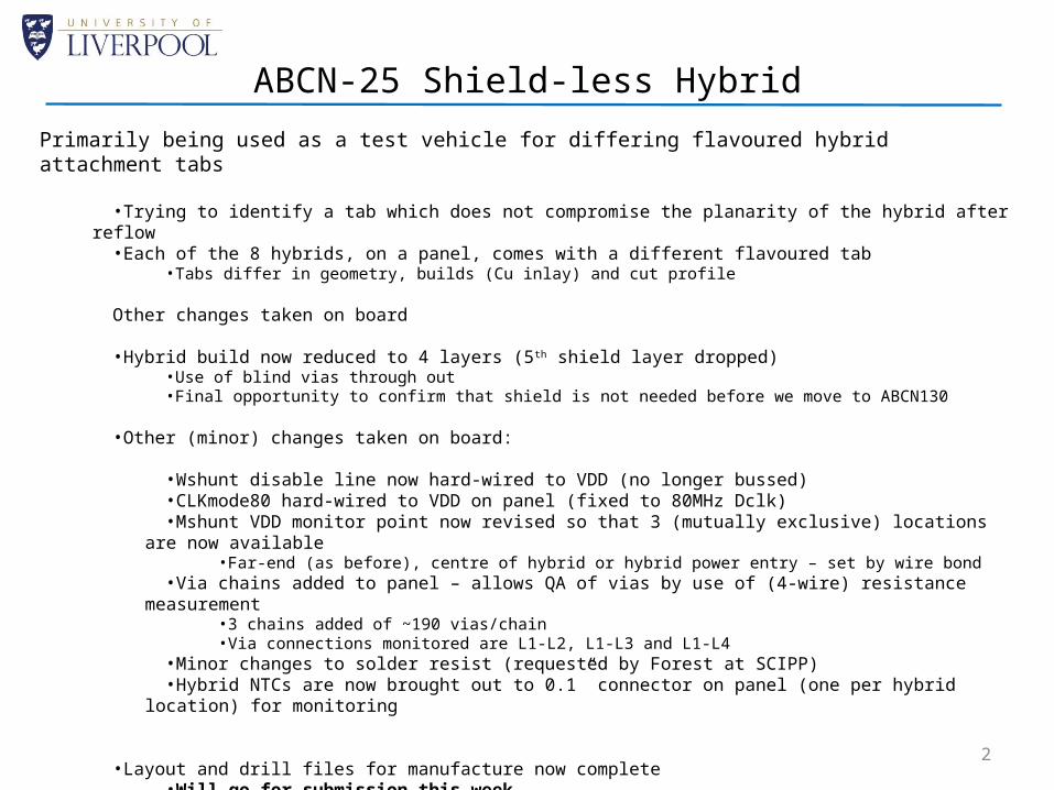
Primarily being used as a test vehicle for differing flavoured hybrid attachment tabs
•Trying to identify a tab which does not compromise the planarity of the hybrid after reflow•Each of the 8 hybrids, on a panel, comes with a different flavoured tab
•Tabs differ in geometry, builds (Cu inlay) and cut profile
Other changes taken on board
•Hybrid build now reduced to 4 layers (5th shield layer dropped)•Use of blind vias through out•Final opportunity to confirm that shield is not needed before we move to ABCN130
•Other (minor) changes taken on board:
•Wshunt disable line now hard-wired to VDD (no longer bussed)•CLKmode80 hard-wired to VDD on panel (fixed to 80MHz Dclk)•Mshunt VDD monitor point now revised so that 3 (mutually exclusive) locations are now available
•Far-end (as before), centre of hybrid or hybrid power entry – set by wire bond•Via chains added to panel – allows QA of vias by use of (4-wire) resistance measurement
•3 chains added of ~190 vias/chain•Via connections monitored are L1-L2, L1-L3 and L1-L4
•Minor changes to solder resist (requested by Forest at SCIPP)•Hybrid NTCs are now brought out to 0.1” connector on panel (one per hybrid location) for monitoring
•Layout and drill files for manufacture now complete•Will go for submission this week
ABCN-25 Shield-less Hybrid

Serial Powering of Modules
Request to implement “Chain of Modules” powering configuration in more sanitary manner
•PCB designed, based on PPB geometry•STAR topology implemented for both power and return (centred on hybrid power feeds and not PCB)•Provides serial powered configuration for a module i.e. not serial powering of hybrids
•Results in 2.5V (~10A) across module
PPB Replacement (PPBR)
SPin
SPout
SPin SPout
STAR Point
Hybrid PowerReturn Return
Pi-filter Pi-filter2.5V/10A
SPout
SPin
V+
V-
V+
V-2 x 10µF22µF
12nH
2 x 10µF 22µF
12nH
3
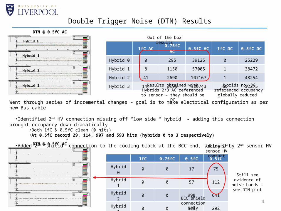
Double Trigger Noise (DTN) Results
1fC AC 0.75fC AC 0.5fC AC 1fC DC 0.5fC DC
Hybrid 0 0 295 39125 0 25229
Hybrid 1 8 1150 57005 1 38472
Hybrid 2 41 2690 107167 1 48254
Hybrid 3 144 3199 120743 60 52275
DTN @ 0.5fC AC
Results obtained with Hybrids 2/3 AC referenced to sensor – they
should be DC
Hybrids now DC referenced occupancy globally reduced
Hybrid 0
Hybrid 1
Hybrid 2
Hybrid 3
Went through series of incremental changes – goal is to make electrical configuration as per new Bus cable
•Identified 2nd HV connection missing off “low side “ hybrid - adding this connection brought occupancy down dramatically•Both 1fC & 0.5fC clean (0 hits)•At 0.5fC record 29, 114, 907 and 593 hits (hybrids 0 to 3 respectively)
•Added 2nd “shield” connection to the cooling block at the BCC end, followed by 2nd sensor HV contact
1fC 0.75fC 0.5fC 0.5fC
Hybrid 0 0 0 17 75
Hybrid 1 0 0 57 112
Hybrid 2 0 0 998 641
Hybrid 3 0 0 539 292
BCC shield connection only
Adding 2nd sensor HV contact
DTN @ 0.5fC AC
Still see evidence of noise bands –
see DTN plot
4
Out of the box results

But DTN doesn’t tell the whole story...
Input noise of module was originally high with normal grounding test configuration
Input noise with PPBR and DC referenced hybrids –
comparable to seen in the past with elevated noise
Input noise with PPBR with both ends of hybrids
referenced to cooling block With 2nd sensor HV contact
Global reduction of ≥50e is now achieved compared to original
5
Noise reduction of ~40e achieved

Irradiation of Hybrid NTCs for future ABC130 modules
•Request from ASIC designers to revise NTC type such that the resistance at 25°C is 1kΩ•HCC temperature measuring circuit has a leakage current which introduces a DC offset •NTCs with high R could be problematic for measurement
•NTCs used on present hybrids are 10kΩ
•Switching to different NTC will require their qualification to expected Upgrade radiation dose •3 candidate manufacturers identified:
•Murata, Vishay and Panasonic•Current family of devices, manufactured by Semitec, don’t go below 10kΩ
•Plan to irradiate the following devices plus reference, vis:•5 x 1kΩ and 5 x 2kΩ - from each manufacturer 30 off total•5 x Semitec (reference)
•Devices will be hooked up to a multiplexed data logger for real time measurement during irradiation
•To be done at CERN PS (July/August) and possibly the irradiation facility at Birmingham
Irradiation of new family of NTCs
6

•ABCN-25 shield-less hybrid is now more or less ready for submission•Issue of planarity of tabs is being addressed•Will come as a 4 layer build – no shield (preparing for the future ABC130 hybrids)•Other minor changes taken on board (see list on slide 2 )
•Serial Powering of modules – configured as “Chain of Modules”•PCB designed with “star” topology has been demonstrated to work•Incremental changes to electrical configuration showed improving noise performance
•Changes reflect configuration of new bus cables•The future for a stavelet with this adopted configuration looks promising
•ABC130 first pass at Pad Ring has been done•Preliminary layout has been demonstrated to fit within the asic geometry of 6mm x 7.9mm
•Irradiation of new family of NTCs•Candidate families of NTCs with lower resistance at 25°C have been identified (1kΩ at 25°C, present NTCs are 10kΩ at
25°C) •Requested for matching up to current HCC design
•Will go for irradiation in summer to qualify their robustness to radiation damage
Summary
7