Embed Size (px)
Citation preview

Stretchable and Reversibly Deformable Radio Frequency AntennasBased on Silver NanowiresLingnan Song,† Amanda C. Myers,† Jacob J. Adams,‡ and Yong Zhu*,†
†Department of Mechanical and Aerospace Engineering, ‡Department of Electrical and Computer Engineering, North Carolina StateUniversity, Raleigh, North Carolina 27695, United States
ABSTRACT: We demonstrate a class of microstrip patch antennas that arestretchable, mechanically tunable, and reversibly deformable. The radiatingelement of the antenna consists of highly conductive and stretchablematerial with screen-printed silver nanowires embedded in the surface layerof an elastomeric substrate. A 3-GHz microstrip patch antenna and a 6-GHz2-element patch array are fabricated. Radiating properties of the antennasare characterized under tensile strain and agree well with the simulationresults. The antenna is reconfigurable because the resonant frequency is afunction of the applied tensile strain. The antenna is thus well suited forapplications like wireless strain sensing. The material and fabricationtechnique reported here could be extended to achieve other types ofstretchable antennas with more complex patterns and multilayer structures.
KEYWORDS: silver nanowire, stretchable antenna, wireless strain sensing, printed electronics, microstrip patch antenna
1. INTRODUCTION
Wearable systems for detecting human motions and monitoringhuman health/wellness have attracted significant attention inrecent years. A variety of wearable sensors,1,2 energy harvest-ing/storage,3,4 and electronic circuits5,6 have been developed,which represents exciting progress toward battery-less (or free)health monitoring. Wearable wireless communication is key toconvey the sensory data and provide remote diagnosis, and aradio frequency antenna is a critical component for the wirelesscommunication.Antennas are conventionally fabricated by printing or etching
metal patterns on rigid substrates, which can easily crease andeven fail to function properly when subjected to mechanicaldeformation (e.g., stretching, folding, or twisting). Thusdevelopment of flexible, stretchable, and conformal antennascalls for new electronic materials and/or new deviceconfigurations. For example, flexible antennas have beenrealized by electroplating thin metal foils (e.g., copper7 andgold8) on elastic dielectric substrates. 3D conformal antennashave been developed by printing silver nanoparticles on a 3Dsurface.9 However, these antennas are not able to withstandtensile strain. Several types of stretchable antennas, includingcone,10 loop,11 dipole,12,13 and patch,14 have been realized byencasing liquid metal alloys into stretchable microchannels.Such stretchable antennas can also be used as self-containedstrain sensors.15 This approach, however, is limited in terms ofscalable manufacturing due to its fabrication complexity andpotential problems caused by leakage of the liquid metals.Recently, stretchable antenna has also been achieved usingcarbon nanotube (CNT) sheet and polymer substrates.16,17
Silver nanowires (AgNWs) have emerged as a promisingmaterial for flexible/transparent18,19 and stretchable electro-
des20 in a number of applications including light emittingdiodes,21 solar cells,22 and wearable sensors.23 In addition toflexible antennas,24,25 AgNWs were recently used in fabricatingstretchable antennas.26 However, the antenna performanceswere not evaluated under tensile strain. In addition, thereversibility under stretching and other deformation modes wasnot demonstrated.In this paper, we report a class of microstrip patch antennas
that are stretchable, mechanically tunable, and reversiblydeformable. The radiating element of the antenna consistedof a highly conductive and stretchable material with AgNWsembedded in the surface layer of an elastomeric substrate. Morespecifically, a 3-GHz microstrip patch antenna and a 6-GHz, 2-element patch array were fabricated. Radiating properties of theantennas were characterized under tensile strain and agreedwell with the simulation results. Since the resonant frequencyincreased with increasing tensile strain, the antenna can be usedfor wireless strain sensing. Finally, the antennas weredemonstrated to maintain the same spectral properties undersevere bending, twisting, and rolling.
2. RESULTS AND DISCUSSION
Figure 1a shows the fabrication procedure for the AgNW/PDMS patch antennas. Two types of patch antennas − thesingle patch (Figure 1b) and 2-element array (Figure 1c) −were fabricated in this study using the same process. Thethickness of the AgNW/PDMS layer is ∼0.5 mm, and the
Received: December 25, 2013Accepted: March 4, 2014Published: March 4, 2014
Research Article
www.acsami.org
© 2014 American Chemical Society 4248 dx.doi.org/10.1021/am405972e | ACS Appl. Mater. Interfaces 2014, 6, 4248−4253
Dow
nloa
ded
via
NO
RT
H C
AR
OL
INA
ST
AT
E U
NIV
on
Mar
ch 9
, 202
0 at
18:
12:4
5 (U
TC
).Se
e ht
tps:
//pub
s.ac
s.or
g/sh
arin
ggui
delin
es f
or o
ptio
ns o
n ho
w to
legi
timat
ely
shar
e pu
blis
hed
artic
les.

separation between the radiating element and the ground planeis ∼1 mm (±0.1 mm).The single patch antenna consists of a rectangular radiating
patch, a ground plane, and a uniform layer of dielectricsubstrate between them. Dimensions of the patch weredesigned based on the transmission-line model, which givesthe width W and the length L as functions of the resonantfrequency f res, the relative permittivity of substrate material εr,and the thickness of substrate h27 (see the ExperimentalSection).The substrate material PDMS has a reported relative
permittivity ranging from εr = 2.67 to 3.00 and loss tangentranging from tanδ = 0.01 to 0.05 over an operating frequencyrange of 1.0 to 5.0 GHz.14 Accordingly, we modeled thesubstrate material with relative permittivity of εr = 2.80 and losstangent of tanδ = 0.02 for the 3-GHz application. Conductivityof the AgNW/PDMS stretchable conductor is ∼8,130 S cm−1
before stretching.20 Here we used a constant conductivity of8,130 S cm−1 for the antenna considering the applied strainswere relatively small.To obtain the resonance frequency of 3 GHz, the rectangular
patch was designed to be 36.0 mm × 29.2 mm, backed with a45.0 mm × 40.0 mm ground plane. To match the inputimpedance with a 2.5 mm × 8.0 mm 50Ω microstrip feed line,the inset feeding method was employed, which left a 3 mmexternal part and eliminated the need for an external matchingnetwork. Length and width of the cutout inset region wereoptimized in ANSYS HFSS to achieve lower return loss andless additional coupling between patch and feed line.The 6-GHz 2-element array patch antenna was designed
similarly with the same material parameters except an increasedloss tangent of tanδ = 0.05. Two identical radiating elementswith dimensions shrinking to 18.0 mm × 14.3 mm werearranged in parallel and fed simultaneously by a feedingnetwork. Since the doubled operating frequency renders theinput impedance more sensitive to inaccuracy in dimensions,we changed the matching strategy by introducing an impedancetransformer at the edge of each radiating element to reducepossible fabrication error. Note that due to the fabricationerror, the obtained resonance frequencies for the patch and the2-element array are 2.92 and 5.92 GHz, respectively.
Simulated radiation patterns of the one and two elementantennas were obtained by far-field calculation in ANSYSHFSS, as shown in Figure 2. Simulation results for the radiation
properties of both antennas are summarized in Table 1 forcomparison. The 2-element array, compared with the singleelement, increases the directivity by 4.5 dB and the fractionalbandwidth by 2.5%, with higher radiation efficiency at the sametime.The patch antennas were characterized experimentally and
compared to the simulated results. Measured and simulatedfrequency responses agreed very well, with the difference withinthe manufacturing imperfection and measurement uncertainty.Figure 3 shows the measured spectrum response of thereflection coefficient over a frequency range of 2 to 4 GHz forthe single patch antenna before stretching, with S11 below −20dB at the center frequency of 2.92 GHz and above −1 dB far
Figure 1. (a) Fabrication procedure for the AgNW/PDMS flexiblepatch antenna and the schematics for (b) microstrip patch antennaand (c) 2-element patch array.
Figure 2. Simulated radiation pattern for the AgNW/PDMS (a)microstrip patch antenna and (b) 2-element patch array.
Table 1. Comparison of Simulated Radiation Properties forMicrostrip Patch Antenna and 2-Element Patch Array
radiation properties monopole patch 2-element patch array
resonant frequency 2.92 GHz 5.92 GHzpeak directivity 4.16 dBi 8.14 dBipeak gain 0.37 dBi 4.90 dBiradiation efficiency 41.83% 48.83%bandwidth 88 MHz (3.0%) 330 MHz (5.5%)
ACS Applied Materials & Interfaces Research Article
dx.doi.org/10.1021/am405972e | ACS Appl. Mater. Interfaces 2014, 6, 4248−42534249

outside the operating region. The bandwidth, defined as thefrequencies where S11 < −10 dB, was 97.5 MHz.We compared the simulated reflection coefficient for the 2-
element array to the measured reflection coefficient from 4 to 8GHz. The array was initially designed with a single operatingband at 6 GHz, while the measured results showed anadditional operating band at around 5.3 GHz. We studied themechanism of the unexpected resonance by introducing smalldimension deviations due to possible fabrication errorscompared to the antenna model with ideal dimensions. As isshown in Figure 4, when we assume that one of the radiating
elements was fabricated larger in length than the other, thesimulated frequency response would extend to the lowerfrequency band and form another band located at around 5.3GHz for a 1 mm deviation in length, which was very close towhat we observed experimentally.Far-field performance for the single patch antenna was tested
in an anechoic chamber. We measured the peak gain overfrequency range of 2 to 4 GHz. Radiation efficiency wasestimated using the measured gain and simulated directivity,which is compared to the simulated radiation efficiency inFigure 5. To further study loss mechanisms of the AgNW/PDMS patch antenna with respect to radiation efficiency, wemodeled antennas composed of four combinations of dielectricsubstrates and metal materials. We considered both AgNW/PDMS conductor with conductivity of 8130 S cm−1 and perfectelectric conductor (PEC) with infinite conductivity for the
metal components. Also, we evaluated both PDMS with losstangent of tanδ = 0.02 and lossless dielectric substrate. Table 2
summarized the simulation results of radiation efficiency for allfour combinations. Compared to the ideal configuration,radiation efficiency was decreased from 100% to around 56%by the lossy substrate and to around 67% by the AgNW/PDMSwith finite conductivity. For completeness, the radiation patternfor the antenna in the E-plane and the H-plane is shown inFigure 6. The stretchable antenna exhibits excellent radiationproperties as well as good agreement with the simulated results.To test the mechanical tunability as a stretchable antenna,
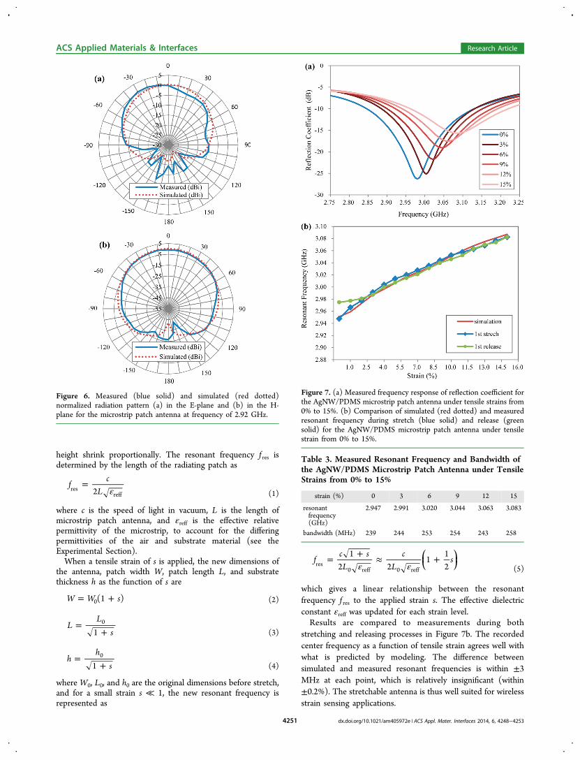
tensile strain ranging from 0% to 15% was applied to theAgNW/PDMS patch antenna in the width direction(perpendicular to the cable connection), while the reflectioncoefficient was collected by the network analyzer simulta-neously. The antenna was tested on a custom-made mechanicaltesting stage, where all the components are made of insulators(e.g., ceramic, glass, and Teflon). Figure 7a shows the measuredfrequency response of the reflection coefficient under tensilestrain from 0% to 15%. With the increasing strain, the spectrumresponse shifted to higher band, the center frequency increasedalmost linearly, and the −10 dB bandwidth remained higherthan 80 MHz, as listed in Table 3. The results suggest thatperformance of the stretchable antenna was not largelycompromised during stretching.The strain was then decreased back to zero on the antenna.
The center frequency was also measured during the releasingprocess. Upon complete release of the strain, the antennareturned to its original resonant frequency demonstratingexcellent reversible deformability (Figure 7b).To analyze the frequency shift due to the applied strain, we
accounted for the changing dimensions as functions of thestrain. PDMS is a typical hyperelastic material where the totalvolume is constant during deformation.28 Therefore when theantenna is elongated in the width direction, the length and
Figure 3. Comparison of measured (blue solid) and simulated (reddotted) reflection coefficient for the AgNW/PDMS microstrip patchantenna.
Figure 4. Comparison of measured (blue solid) and simulatedreflection coefficient for the AgNW/PDMS 2-element patch array,with ideal dimensions (red dotted) and 1 mm deviation in length forone of the radiating elements (red dashed).
Figure 5. Estimated (blue solid) and simulated (red dotted) radiationefficiency for the microstrip patch antenna.
Table 2. Comparison of Simulated Radiation Efficiency ofAntennas in Different Dielectric and Metal Materials
substrate metal radiation efficiency
lossy PDMS AgNW/PDMS 41.53%lossy PDMS PEC 55.76%lossless material AgNW/PDMS 67.20%lossless material PEC 100%
ACS Applied Materials & Interfaces Research Article
dx.doi.org/10.1021/am405972e | ACS Appl. Mater. Interfaces 2014, 6, 4248−42534250
height shrink proportionally. The resonant frequency f res isdetermined by the length of the radiating patch as
ε=f
cL2res
reff (1)
where c is the speed of light in vacuum, L is the length ofmicrostrip patch antenna, and εreff is the effective relativepermittivity of the microstrip, to account for the differingpermittivities of the air and substrate material (see theExperimental Section).When a tensile strain of s is applied, the new dimensions of
the antenna, patch width W, patch length L, and substratethickness h as the function of s are
= +W W s(1 )0 (2)
=+
LL
s10
(3)
=+
hh
s10
(4)
where W0, L0, and h0 are the original dimensions before stretch,and for a small strain s ≪ 1, the new resonant frequency isrepresented as
ε ε= + ≈ +⎜ ⎟
⎛⎝
⎞⎠f
c sL
cL
s1
2 21
12res
0 reff 0 reff (5)
which gives a linear relationship between the resonantfrequency f res to the applied strain s. The effective dielectricconstant εreff was updated for each strain level.Results are compared to measurements during both
stretching and releasing processes in Figure 7b. The recordedcenter frequency as a function of tensile strain agrees well withwhat is predicted by modeling. The difference betweensimulated and measured resonant frequencies is within ±3MHz at each point, which is relatively insignificant (within±0.2%). The stretchable antenna is thus well suited for wirelessstrain sensing applications.
Figure 6. Measured (blue solid) and simulated (red dotted)normalized radiation pattern (a) in the E-plane and (b) in the H-plane for the microstrip patch antenna at frequency of 2.92 GHz.
Figure 7. (a) Measured frequency response of reflection coefficient forthe AgNW/PDMS microstrip patch antenna under tensile strains from0% to 15%. (b) Comparison of simulated (red dotted) and measuredresonant frequency during stretch (blue solid) and release (greensolid) for the AgNW/PDMS microstrip patch antenna under tensilestrain from 0% to 15%.
Table 3. Measured Resonant Frequency and Bandwidth ofthe AgNW/PDMS Microstrip Patch Antenna under TensileStrains from 0% to 15%
strain (%) 0 3 6 9 12 15
resonantfrequency(GHz)
2.947 2.991 3.020 3.044 3.063 3.083
bandwidth (MHz) 239 244 253 254 243 258
ACS Applied Materials & Interfaces Research Article
dx.doi.org/10.1021/am405972e | ACS Appl. Mater. Interfaces 2014, 6, 4248−42534251

To further demonstrate the reversible deformability of ourantennas, they were subjected to other deformation modesincluding bending, twisting, and rolling, as shown in Figure 8.
The antenna was deformed by bending by 90° along the longaxis, twisting along the long axis, rolling on both axes. After thedeformed antenna was returned to its original state, itmaintained almost the same spectral properties with differenceof the resonant frequencies within ±1 MHz (<0.1%) beforeand after deformation in each case, which demonstrates that theAgNW/PDMS flexible antenna is reversibly deformable androbust.
3. CONCLUSIONWe have demonstrated a class of microstrip patch antennas thatare stretchable, mechanically tunable, and reversibly deform-able. A 3-GHz patch antenna and a 6-GHz 2-element patcharray were fabricated. Radiating properties of the antennas werecharacterized under tensile strain, which agreed well with thesimulation results. The antenna was mechanically tunable,enabling the resonant frequency to change as a function of theapplied tensile strain. Thus it was well suited for applicationslike wireless strain sensing. The radiation efficiency was limitedby losses in both the PDMS substrate and AgNW. Theantennas were also demonstrated to maintain the same spectralproperties after severe bending, twisting, and rolling. Thematerial and fabrication technique reported here could beextended to achieve other types of stretchable antennas withmore complex patterns and multilayer structures.
■ EXPERIMENTAL SECTIONFabrication Process. AgNWs with an average diameter of ∼90
nm and length in the range of 10−60 μm were synthesized in solution(from Blue Nano).20 They are dispersed in ethanol with aconcentration of 10 mg/mL. As shown in Figure 1a, the antennapattern was cut out from a stencil mask on a precleaned substrate suchas silicon (Si) wafer. AgNWs solution was drop casted into the maskon top of a hot plate (set at 55 °C) and then dried to form aconductive film of AgNWs with the desired antenna pattern. Afterpeeling off the stencil mask, liquid PDMS was casted on top of the
AgNW film and heated at 100 °C for 1 h to cure. When the curedPDMS layer was peeled off the substrate, the AgNW film wasembedded into the PDMS forming a surface layer both conductive andstretchable. Fabrication of the ground plane layer followed the sameprocedure and then bonded with the patch layer before the liquidPDMS cured.
Modeling and Design. The width W and the length L aredesigned based on the transmission-line model27
ε=
+W
cf2
21rres (6)
ε= − ΔL
cf
L2
2res reff (7)
where
εε ε
=+
+−
+−⎡
⎣⎢⎤⎦⎥
hW
12
12
1 12reffr r
1/2
(8)
ε
εΔ =
+ +
− +
( )( )
L h0.412( 0.3) 0.264
( 0.258) 0.8
Wh
Wh
reff
reff (9)
with ΔL as the “extended” length at each end because fringing fields atthe patch edges make the length appear larger electrically thanphysically. For low frequencies (<10 GHz) the effective dielectricconstant is essentially constant, referred to as the static values andgiven by eq 8. Equation 9 is a common approximate relation for theextension of length depending on the effective dielectric constant εreffand the width-to-height ratio (W/h). Typically ΔL ≪ L.
Antenna Measurement. An antenna was connected to a coaxialcable by a SMA connector. S-parameters were collected using anAgilent E5071C Vector Network Analyzer to measure the resonantfrequency and reflection coefficient. Radiation patterns were measuredin the anechoic chamber at the NC State Remote Educational AntennaLab (REAL). 2D pattern cuts were measured in the orthogonal E- andH-planes (YZ and XZ planes). Each cut was obtained by rotating theantenna under test (AUT) in 10 degree increments while recordingthe received signal with a broadband horn antenna (A.H. Systems) toproduce the relative pattern plot. Absolute gain was calculated via gaincomparison to a standard gain horn (A.H. Systems). The results givenin the paper represent the copolar radiation patterns and gain.
■ AUTHOR INFORMATIONCorresponding Author*E-mail: [email protected] authors declare no competing financial interest.
■ ACKNOWLEDGMENTSThis work was supported in part by the National ScienceFoundation through the EFRI program (EFRI-1240438) andASSIST Engineering Research Center at NCSU (EEC-1160483). The authors would like to thank Dr. MichaelDickey for providing access to their custom-made mechanicaltesting stage. L.S. is grateful to the Global Engagement inAcademic Research (GEAR) Program at NCSU.
■ REFERENCES(1) Kim, D.-H.; Lu, N.; Ma, R.; Kim, Y.-S.; Kim, R.-H.; Wang, S.; Wu,J.; Won, S. M.; Tao, H.; Islam, A.; Yu, K. J.; Kim, T.; Chowdhury, R.;Ying, M.; Xu, L.; Li, M.; Chung, H.-J.; Keum, H.; McCormick, M.; Liu,P.; Zhang, Y.-W.; Omenetto, F. G.; Huang, Y.; Coleman, T.; Rogers, J.A. Epidermal Electronics. Science 2011, 333, 838−843.(2) Lipomi, D. J.; Vosgueritchian, M.; Tee, B. C.-K.; Hellstrom, S. L.;Lee, J. A.; Fox, C. H.; Bao, Z. Skin-Like Pressure and Strain Sensors
Figure 8. Photographs of a stretchable microstrip patch antennacomposed of AgNW/PDMS flexible conductor: (a) relaxed, (b) bent,(c) twisted, and (d) rolled.
ACS Applied Materials & Interfaces Research Article
dx.doi.org/10.1021/am405972e | ACS Appl. Mater. Interfaces 2014, 6, 4248−42534252

Based on Transparent Elastic Films of Carbon Nanotubes. Nat.Nanotechnol. 2011, 788−792.(3) Lee, M.; Chen, C.-Y.; Wang, S.; Cha, S. N.; Park, Y. J.; Kim, J. M.;Chou, L.-J.; Wang, Z. L. A Hybrid Piezoelectric Structure for WearableNanogenerators. Adv. Mater. 2012, 24, 1759−1764.(4) Yu, C.; Masarapu, C.; Rong, J.; Wei, B.; Jiang, H. StretchableSupercapacitors Based on Buckled Single-Walled Carbon-NanotubeMacrofilms. Adv. Mater. 2009, 21, 4793−4797.(5) Sekitani, T.; Zschieschang, U.; Klauk, H.; Someya, T. FlexibleOrganic Transistors and Circuits with Extreme Bending Stability. Nat.Mater. 2010, 9, 4−6.(6) Artukovic, E.; Kaempgen, M.; Hecht, D. S.; Roth, S.; Gruner, G.Transparent and Flexible Carbon Nanotube Transistors. Nano Lett.2005, 5, 757−760.(7) Lin, C.; Chang, C.; Cheng, Y. T.; Member, S.; Jou, C. F.Development of a Flexible SU-8/PDMS-Based Antenna. IEEEAntennas Wireless Propag. Lett. 2011, 10, 1108−1111.(8) Hage-ali, S.; Tiercelin, N.; Coquet, P.; Sauleau, R.; Pernod, P.;Scientifique, C. Millimeter-Wave Patch Array Antenna on UltraFlexible Micromachined Polydimethylsiloxane (PDMS) Substrate.Antennas Propag. Soc. Int. Symp. 2009, 1, 5−8.(9) Adams, J. J.; Duoss, E. B.; Malkowski, T. F.; Motala, M. J.; Ahn,B. Y.; Nuzzo, R. G.; Bernhard, J. T.; Lewis, J. A. Conformal Printing ofElectrically Small Antennas on Three-Dimensional Surfaces. Adv.Mater. 2011, 23, 1335−40.(10) Cheng, S.; Member, S.; Wu, Z.; Hallbjorner, P.; Hjort, K.Foldable and Stretchable Liquid Metal Planar Inverted Cone Antenna.IEEE Trans. Antennas Propag. 2009, 57, 3765−3771.(11) Cheng, S.; Rydberg, A.; Hjort, K.; Wu, Z. Liquid MetalStretchable Unbalanced Loop Antenna. Appl. Phys. Lett. 2009, 94,144103.(12) So, J.-H.; Thelen, J.; Qusba, A.; Hayes, G. J.; Lazzi, G.; Dickey,M. D. Reversibly Deformable and Mechanically Tunable FluidicAntennas. Adv. Funct. Mater. 2009, 19, 3632−3637.(13) Kubo, M.; Li, X.; Kim, C.; Hashimoto, M.; Wiley, B. J.; Ham, D.;Whitesides, G. M. Stretchable Microfluidic Radiofrequency Antennas.Adv. Mater. 2010, 22, 2749−2752.(14) Hayes, G. J.; Qusba, A.; Dickey, M. D.; Lazzi, G. Flexible LiquidMetal Alloy (EGaIn) Microstrip Patch Antenna. IEEE Trans. AntennasPropag. 2012, 60, 2151−2156.(15) Cheng, S.; Wu, Z. A Microfluidic, Reversibly Stretchable, Large-Area Wireless Strain Sensor. Adv. Funct. Mater. 2011, 21, 2282−2290.(16) Zhou, Y.; Bayram, Y.; Dai, L.; Volakis, J. L. Conformal Load-Bearing Polymer-Carbon Nanotube Antennas and RF Front-Ends.Proc. IEEE Antennas Propag. Soc. Int. Symp. 2009, 1−4.(17) Zhou, Y.; Bayram, Y.; Member, S.; Du, F.; Dai, L.; Volakis, J. L.Polymer-Carbon Nanotube Sheets for Conformal Load BearingAntennas. IEEE Trans. Antennas Propag. 2010, 58, 2169−2175.(18) Lee, J. Y.; Connor, S. T.; Cui, Y.; Peumans, P. Solution-Processed Metal Nanowire Mesh Transparent Electrodes. Nano Lett.2008, 8, 689−692.(19) De, S.; Higgins, T. M.; Lyons, P. E.; Doherty, E. M.; Nirmalraj,P. N.; Blau, W. J.; Boland, J. J.; Coleman, J. N. Silver NanowireNetworks as Flexible, Tranparent, Conducting Films: Extremely HighDC to Optical Conductivity Ratios. ACS Nano 2009, 3, 1767−1774.(20) Xu, F.; Zhu, Y. Highly Conductive and Stretchable SilverNanowire Conductors. Adv. Mater. 2012, 24, 5117−5122.(21) Yu, Z.; Niu, X.; Liu, Z.; Pei, Q. Intrinsically Stretchable PolymerLight-Emitting Devices Using Carbon Nanotube-Polymer CompositeElectrodes. Adv. Mater. 2011, 23, 3989−3994.(22) Yu, Z.; Li, L.; Zhang, Q.; Hu, W.; Pei, Q. Silver Nanowire-Polymer Composite Electrodes for Efficient Polymer Solar Cells. Adv.Mater. 2011, 23, 4453−4457.(23) Yao, S.; Zhu, Y. Wearable Multifunctional Sensors using PrintedStretchable Conductors made of Silver Nanowires. Nanoscale 2014, 6,2345−2352.(24) Nogi, M.; Komoda, N.; Otsuka, K.; Suganuma, K. FoldableNanopaper Antennas for Origami Electronics. Nanoscale 2013, 5,4395−4399.
(25) Komoda, N.; Nogi, M.; Suganuma, K.; Kohno, K.; Akiyamac, Y.;Otsukac, K. Printed Silver Nanowire Antennas with Low Signal Loss atHigh-Frequency Radio. Nanoscale 2012, 4, 3148−3153.(26) Rai, T.; Dantes, P.; Bahreyni, B.; Kim, W. S. A Stretchable RFAntenna with Silver Nanowires. IEEE Electron Device Lett. 2013, 34,544−546.(27) Balanis, C. A. Antenna Theory: Analysis and Design, 3rd ed.;Wiley: Hoboken, NJ, 2005; Chapter 14, pp 816−820.(28) Xu, F.; Durham, J. D.; Wiley, B. J.; Zhu, Y. Strain-ReleaseAssembly of Nanowires on Stretchable Substrates. ACS Nano 2011, 5,1556−1563.
ACS Applied Materials & Interfaces Research Article
dx.doi.org/10.1021/am405972e | ACS Appl. Mater. Interfaces 2014, 6, 4248−42534253