Embed Size (px)
Citation preview
Stresses in the edges of cold bent glass panes
Spanning in de randen van koud gevormde glasplaten
The final report of the BSc End-work
Dong Li
1300237
2012 Delft
Bachelor end work Stresses in the rims of cold bent glass panes
Preface
This is the final report of the BSc End-work of Civil Engineering (CT3000-09) of TU Delft. The
research is about stresses in the rims of cold bent glass panes.
I would like to thank my supervisors to sharing their knowledge and for providing assistance
during the realization of this report.
Delft Jan. 2012
Dong Li
Supervisors:
Dr. Ir. P.C.J. Hoogenboom
Delft University of Technology - Faculty of Civil Engineering and Geosciences - Section Structural
Mechanics
Ir. S. Pasterkamp
Delft University of Technology - Department Design and Construction - Structural and Building
Engineering
Bachelor end work Stresses in the rims of cold bent glass panes
TABLE OF CONTENTS
Stresses in the edges of cold bent glass panes .................................................................................. 1
Preface .............................................................................................................................................. 2
TABLE OF CONTENTS ......................................................................................................................... 3
1. Introduction .............................................................................................................................. 4
1.1 Problem statement.............................................................................................................. 4
1.2 Objective ............................................................................................................................. 5
1.3 Solution method.................................................................................................................. 5
1.4 Report structure .................................................................................................................. 5
2. Theory ....................................................................................................................................... 6
3. Models ...................................................................................................................................... 8
3.1.1 Material properties .................................................................................................. 8
3.1.2 Boundary conditions ................................................................................................ 8
3.1.3 Dimensions ............................................................................................................... 8
3.2 Shell model .......................................................................................................................... 9
3.3 Solid model ........................................................................................................................ 13
3.3.1 Data information: ................................................................................................... 14
3.3.2 Solid 186 ................................................................................................................. 17
3.3.3 Mesh size ................................................................................................................ 18
3.3.4 Improve the model ................................................................................................. 20
4. Derivation ................................................................................................................................ 22
5. Alternative derivation ............................................................................................................. 23
6. Confirmation .......................................................................................................................... 25
7. CONCLUSIONS ......................................................................................................................... 29
8. REFERENCES ............................................................................................................................ 30
9. Appendix ................................................................................................................................. 31
Bachelor end work Stresses in the rims of cold bent glass panes
1. Introduction
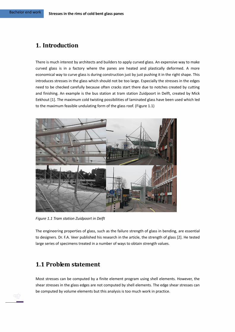
There is much interest by architects and builders to apply curved glass. An expensive way to make
curved glass is in a factory where the panes are heated and plastically deformed. A more
economical way to curve glass is during construction just by just pushing it in the right shape. This
introduces stresses in the glass which should not be too large. Especially the stresses in the edges
need to be checked carefully because often cracks start there due to notches created by cutting
and finishing. An example is the bus station at tram station Zuidpoort in Delft, created by Mick
Eekhout [1]. The maximum cold twisting possibilities of laminated glass have been used which led
to the maximum feasible undulating form of the glass roof. (Figure 1.1)
Figure 1.1 Tram station Zuidpoort in Delft
The engineering properties of glass, such as the failure strength of glass in bending, are essential
to designers. Dr. F.A. Veer published his research in the article, the strength of glass [2]. He tested
large series of specimens treated in a number of ways to obtain strength values.
1.1 Problem statement
Most stresses can be computed by a finite element program using shell elements. However, the
shear stresses in the glass edges are not computed by shell elements. The edge shear stresses can
be computed by volume elements but this analysis is too much work in practice.
Bachelor end work Stresses in the rims of cold bent glass panes
1.2 Objective
Derive a formula for the shear stress in glass pane edges as a function of the edge shear force and
the edge torsion moment.
1.3 Solution method
Model a square glass pane in ANSYS, once with shell elements and once with volume elements
(solid). The glass pane models will be loaded in the corners to impose a curvature. Accurately
determine the shear forces, torsion moments and the shear stress in the rim. Develop a formula
for calculating the edge shear stress.
1.4 Report structure
The first section, describes the problem of this thesis. The shell element model and volume
element model are given in Section 2. The calculation is presented in Section 3. And the
conclusions are presented in Section 4.
Bachelor end work Stresses in the rims of cold bent glass panes
2. Theory
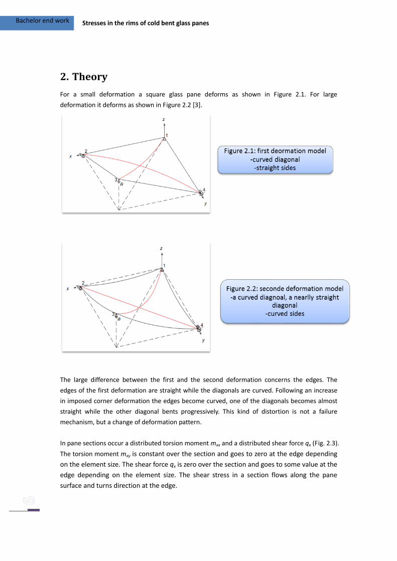
For a small deformation a square glass pane deforms as shown in Figure 2.1. For large
deformation it deforms as shown in Figure 2.2 [3].
The large difference between the first and the second deformation concerns the edges. The
edges of the first deformation are straight while the diagonals are curved. Following an increase
in imposed corner deformation the edges become curved, one of the diagonals becomes almost
straight while the other diagonal bents progressively. This kind of distortion is not a failure
mechanism, but a change of deformation pattern.
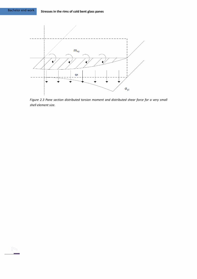
In pane sections occur a distributed torsion moment mxx and a distributed shear force qx (Fig. 2.3).
The torsion moment mxy is constant over the section and goes to zero at the edge depending
on the element size. The shear force qx is zero over the section and goes to some value at the
edge depending on the element size. The shear stress in a section flows along the pane
surface and turns direction at the edge.
Bachelor end work Stresses in the rims of cold bent glass panes
Figure 2.3 Pane section distributed torsion moment and distributed shear force for a very small
shell element size.
Bachelor end work Stresses in the rims of cold bent glass panes
3. Models
Two models have been made; a shell model and a solid model (3D model). Both models have
been made in ANSYS using script.
3.1.1 Material properties
A linear isotropic material model has been used. The Modulus of Elasticity (Young’s modulus) and
Poisson’s ratio are E = 72000 N/mm² and ν = 0.23.
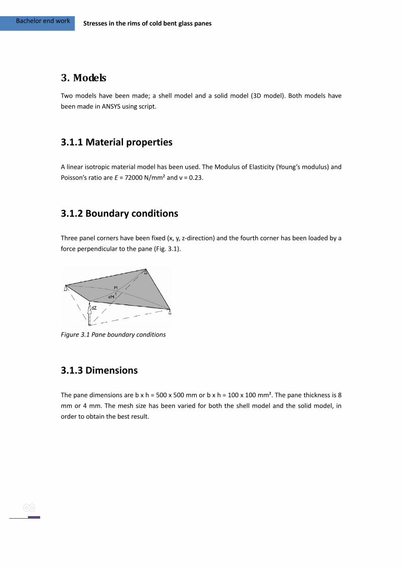
3.1.2 Boundary conditions
Three panel corners have been fixed (x, y, z-direction) and the fourth corner has been loaded by a
force perpendicular to the pane (Fig. 3.1).
Figure 3.1 Pane boundary conditions
3.1.3 Dimensions
The pane dimensions are b x h = 500 x 500 mm or b x h = 100 x 100 mm². The pane thickness is 8
mm or 4 mm. The mesh size has been varied for both the shell model and the solid model, in
order to obtain the best result.
Bachelor end work Stresses in the rims of cold bent glass panes
3.2 Shell model
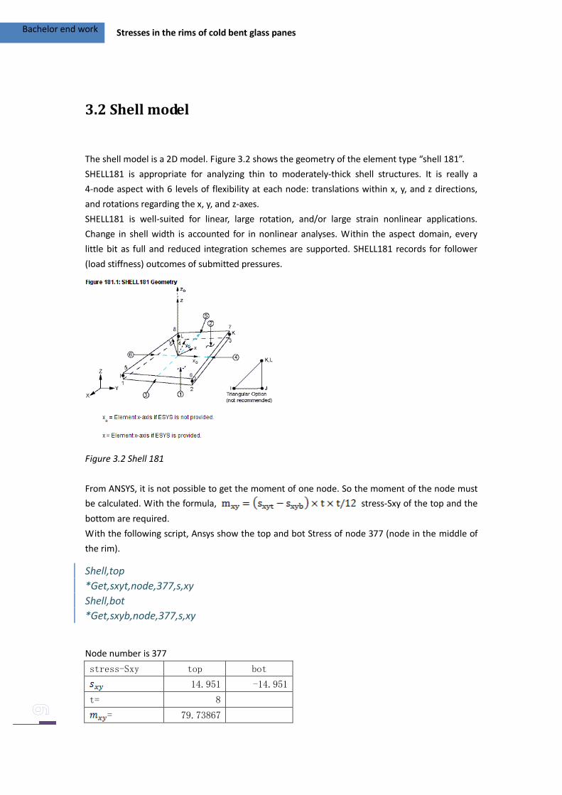
The shell model is a 2D model. Figure 3.2 shows the geometry of the element type “shell 181”.
SHELL181 is appropriate for analyzing thin to moderately-thick shell structures. It is really a
4-node aspect with 6 levels of flexibility at each node: translations within x, y, and z directions,
and rotations regarding the x, y, and z-axes.
SHELL181 is well-suited for linear, large rotation, and/or large strain nonlinear applications.
Change in shell width is accounted for in nonlinear analyses. Within the aspect domain, every
little bit as full and reduced integration schemes are supported. SHELL181 records for follower
(load stiffness) outcomes of submitted pressures.
Figure 3.2 Shell 181
From ANSYS, it is not possible to get the moment of one node. So the moment of the node must
be calculated. With the formula, stress-Sxy of the top and the
bottom are required.
With the following script, Ansys show the top and bot Stress of node 377 (node in the middle of
the rim).
Node number is 377
stress-Sxy top bot
14.951 -14.951
t= 8
= 79.73867
Shell,top
*Get,sxyt,node,377,s,xy
Shell,bot
*Get,sxyb,node,377,s,xy
Bachelor end work Stresses in the rims of cold bent glass panes
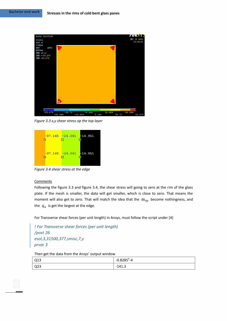
Figure 3.3 x,y shear stress op the top layer
Figure 3.4 shear stress at the edge
Comments
Following the figure 3.3 and figure 3.4, the shear stress will going to zero at the rim of the glass
plate. If the mesh is smaller, the data will get smaller, which is close to zero. That means the
moment will also get to zero. That will match the idea that the become nothingness, and
the is get the largest at the edge.
For Transverse shear forces (per unit length) in Ansys, must follow the script under [4]
Then get the data from the Ansys’ output window
Q13 -0.8285e-4
Q23 -141.3
! For Transverse shear forces (per unit length)
/post 26
esol,3,31500,377,smisc,7,y
prvar 3
Bachelor end work Stresses in the rims of cold bent glass panes
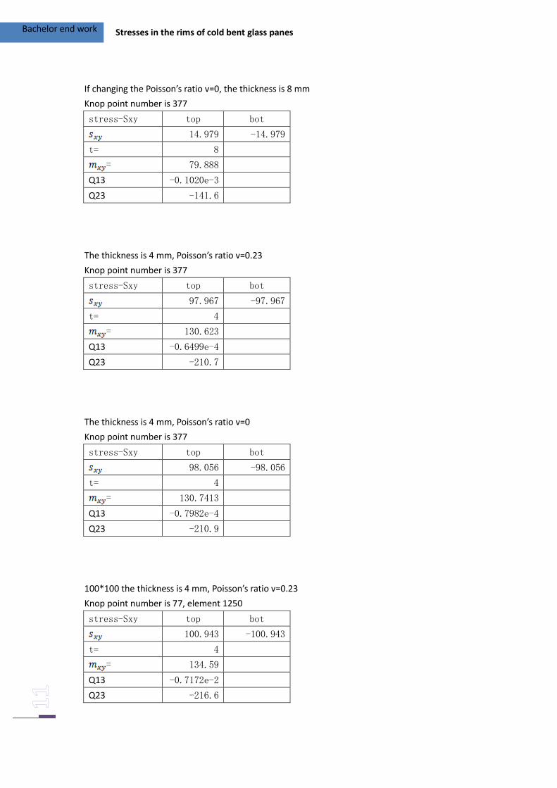
If changing the Poisson’s ratio v=0, the thickness is 8 mm
Knop point number is 377
stress-Sxy top bot
14.979 -14.979
t= 8
= 79.888
Q13 -0.1020e-3
Q23 -141.6
The thickness is 4 mm, Poisson’s ratio v=0.23
Knop point number is 377
stress-Sxy top bot
97.967 -97.967
t= 4
= 130.623
Q13 -0.6499e-4
Q23 -210.7
The thickness is 4 mm, Poisson’s ratio v=0
Knop point number is 377
stress-Sxy top bot
98.056 -98.056
t= 4
= 130.7413
Q13 -0.7982e-4
Q23 -210.9
100*100 the thickness is 4 mm, Poisson’s ratio v=0.23
Knop point number is 77, element 1250
stress-Sxy top bot
100.943 -100.943
t= 4
= 134.59
Q13 -0.7172e-2
Q23 -216.6
Bachelor end work Stresses in the rims of cold bent glass panes
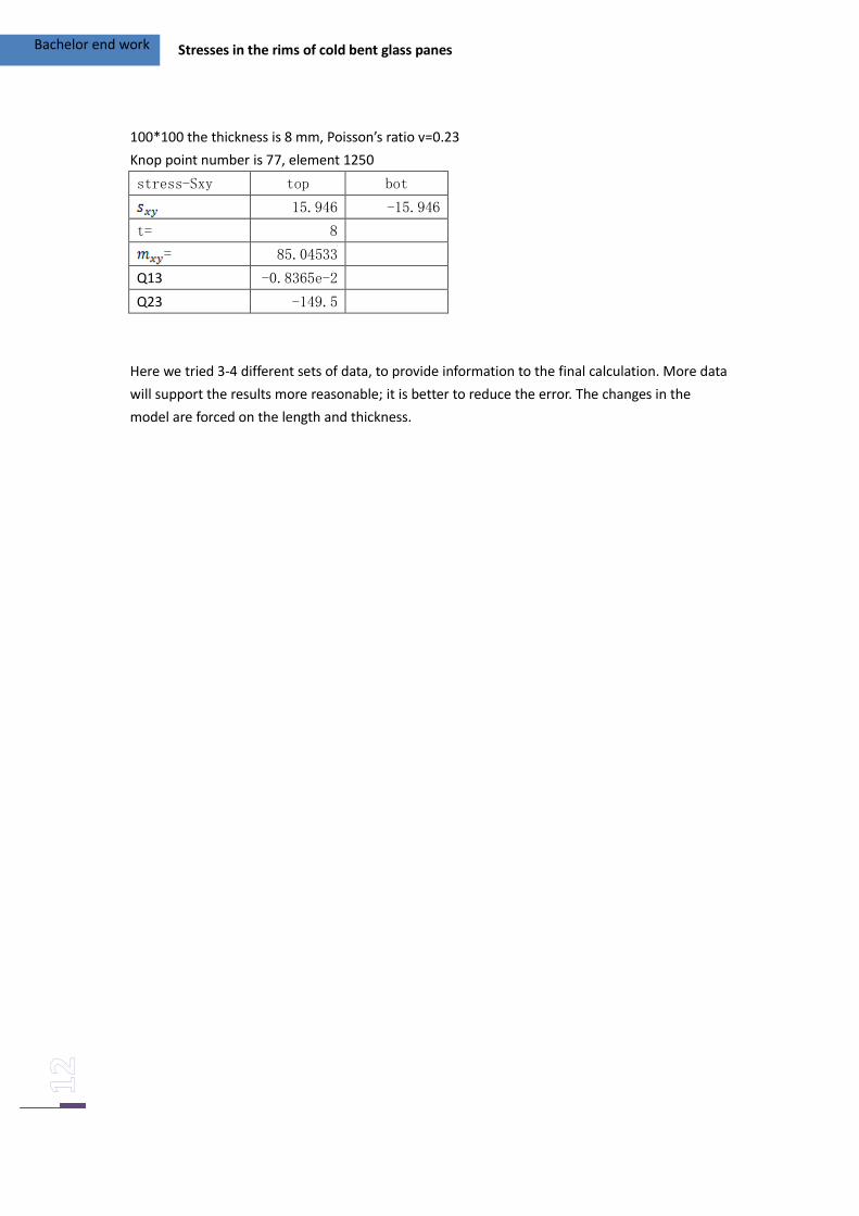
100*100 the thickness is 8 mm, Poisson’s ratio v=0.23
Knop point number is 77, element 1250
stress-Sxy top bot
15.946 -15.946
t= 8
= 85.04533
Q13 -0.8365e-2
Q23 -149.5
Here we tried 3-4 different sets of data, to provide information to the final calculation. More data
will support the results more reasonable; it is better to reduce the error. The changes in the
model are forced on the length and thickness.
Bachelor end work Stresses in the rims of cold bent glass panes
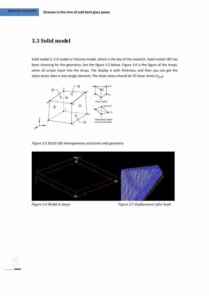
3.3 Solid model
Solid model is 3-d model or Volume model, which is the key of the research. Solid model 185 has
been choosing for the geometry. See the figure 3.5 below. Figure 3.6 is the figure of the Ansys,
when all scripts input into the Ansys. The display is with thickness, and then you can get the
shear-stress data in one assign element. The shear stress should be YZ-shear stress ( ).
Figure 3.6 Model in Ansys Figure 3.7 displacement after loads
Figure 3.5 SOLID 185 Homogeneous structural solid geometry
Bachelor end work Stresses in the rims of cold bent glass panes
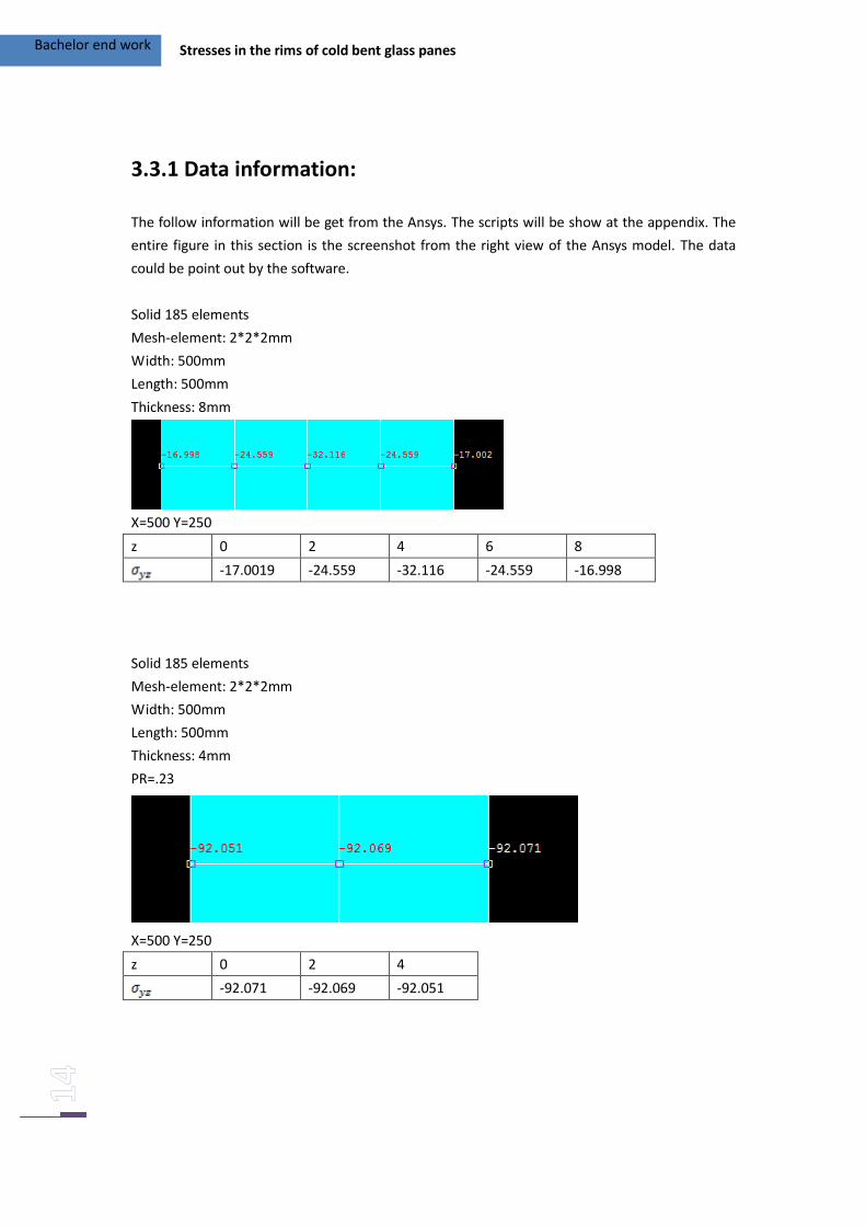
3.3.1 Data information:
The follow information will be get from the Ansys. The scripts will be show at the appendix. The
entire figure in this section is the screenshot from the right view of the Ansys model. The data
could be point out by the software.
Solid 185 elements
Mesh-element: 2*2*2mm
Width: 500mm
Length: 500mm
Thickness: 8mm
X=500 Y=250
z 0 2 4 6 8
-17.0019 -24.559 -32.116 -24.559 -16.998
Solid 185 elements
Mesh-element: 2*2*2mm
Width: 500mm
Length: 500mm
Thickness: 4mm
PR=.23
X=500 Y=250
z 0 2 4
-92.071 -92.069 -92.051
Bachelor end work Stresses in the rims of cold bent glass panes
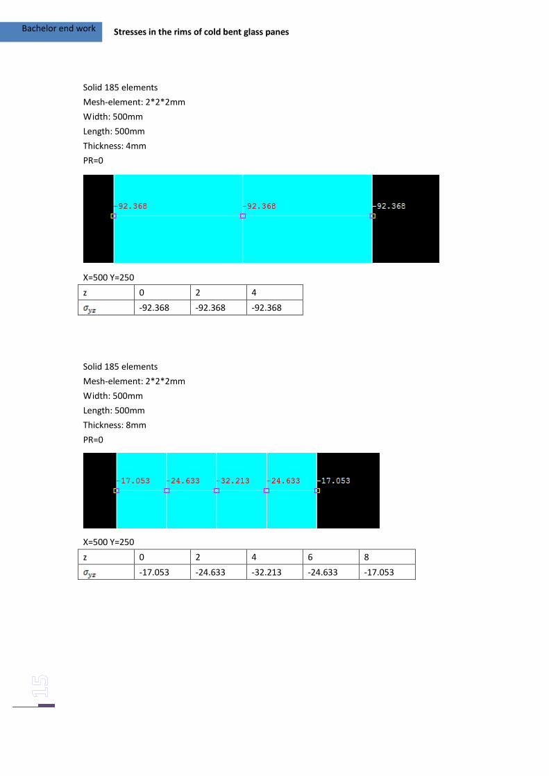
Solid 185 elements
Mesh-element: 2*2*2mm
Width: 500mm
Length: 500mm
Thickness: 4mm
PR=0
X=500 Y=250
z 0 2 4
-92.368 -92.368 -92.368
Solid 185 elements
Mesh-element: 2*2*2mm
Width: 500mm
Length: 500mm
Thickness: 8mm
PR=0
X=500 Y=250
z 0 2 4 6 8
-17.053 -24.633 -32.213 -24.633 -17.053
Bachelor end work Stresses in the rims of cold bent glass panes
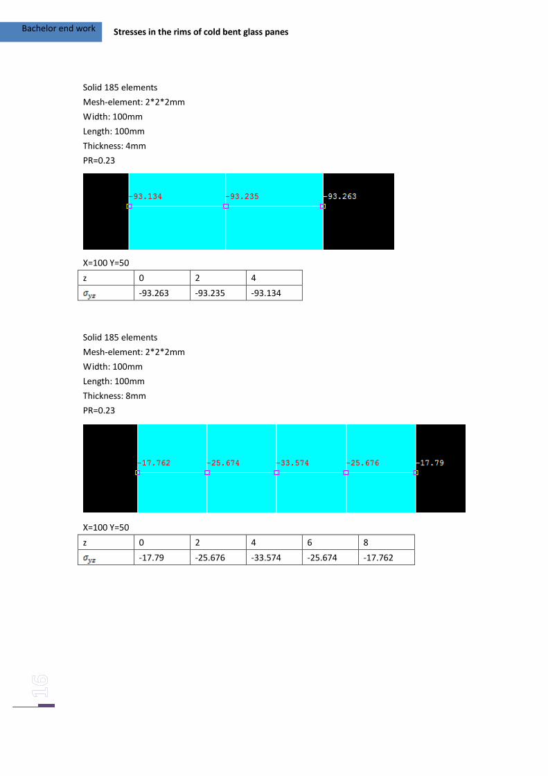
Solid 185 elements
Mesh-element: 2*2*2mm
Width: 100mm
Length: 100mm
Thickness: 4mm
PR=0.23
X=100 Y=50
z 0 2 4
-93.263 -93.235 -93.134
Solid 185 elements
Mesh-element: 2*2*2mm
Width: 100mm
Length: 100mm
Thickness: 8mm
PR=0.23
X=100 Y=50
z 0 2 4 6 8
-17.79 -25.676 -33.574 -25.674 -17.762
Bachelor end work Stresses in the rims of cold bent glass panes
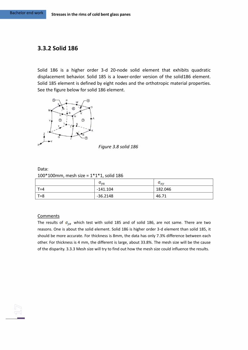
3.3.2 Solid 186
Solid 186 is a higher order 3-d 20-node solid element that exhibits quadratic
displacement behavior. Solid 185 is a lower-order version of the solid186 element.
Solid 185 element is defined by eight nodes and the orthotropic material properties.
See the figure below for solid 186 element.
Figure 3.8 solid 186
Data:
100*100mm, mesh size = 1*1*1, solid 186
T=4 -141.104 182.046
T=8 -36.2148 46.71
Comments
The results of which test with solid 185 and of solid 186, are not same. There are two
reasons. One is about the solid element. Solid 186 is higher order 3-d element than solid 185, it
should be more accurate. For thickness is 8mm, the data has only 7.3% difference between each
other. For thickness is 4 mm, the different is large, about 33.8%. The mesh size will be the cause
of the disparity. 3.3.3 Mesh size will try to find out how the mesh size could influence the results.
Bachelor end work Stresses in the rims of cold bent glass panes
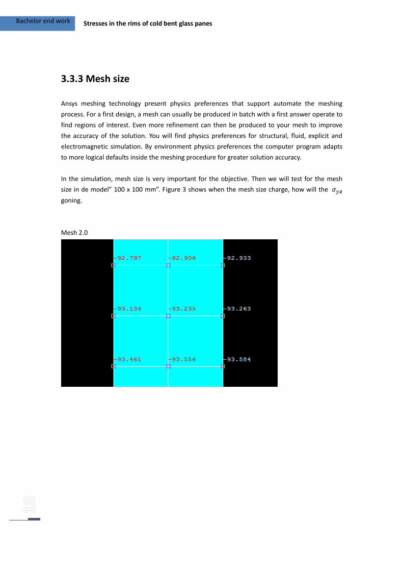
3.3.3 Mesh size
Ansys meshing technology present physics preferences that support automate the meshing
process. For a first design, a mesh can usually be produced in batch with a first answer operate to
find regions of interest. Even more refinement can then be produced to your mesh to improve
the accuracy of the solution. You will find physics preferences for structural, fluid, explicit and
electromagnetic simulation. By environment physics preferences the computer program adapts
to more logical defaults inside the meshing procedure for greater solution accuracy.
In the simulation, mesh size is very important for the objective. Then we will test for the mesh
size in de model” 100 x 100 mm”. Figure 3 shows when the mesh size charge, how will the
goning.
Mesh 2.0
Bachelor end work Stresses in the rims of cold bent glass panes
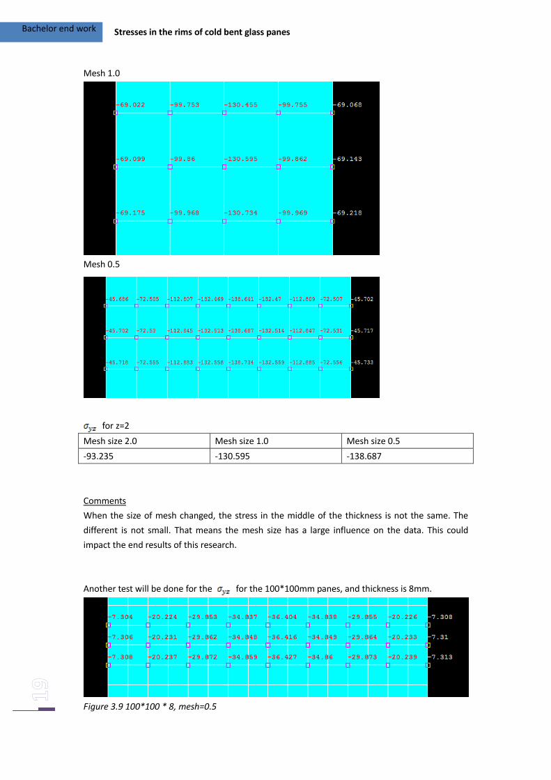
Mesh 1.0
Mesh 0.5
for z=2
Mesh size 2.0 Mesh size 1.0 Mesh size 0.5
-93.235 -130.595 -138.687
Comments
When the size of mesh changed, the stress in the middle of the thickness is not the same. The
different is not small. That means the mesh size has a large influence on the data. This could
impact the end results of this research.
Another test will be done for the for the 100*100mm panes, and thickness is 8mm.
Figure 3.9 100*100 * 8, mesh=0.5
Bachelor end work Stresses in the rims of cold bent glass panes
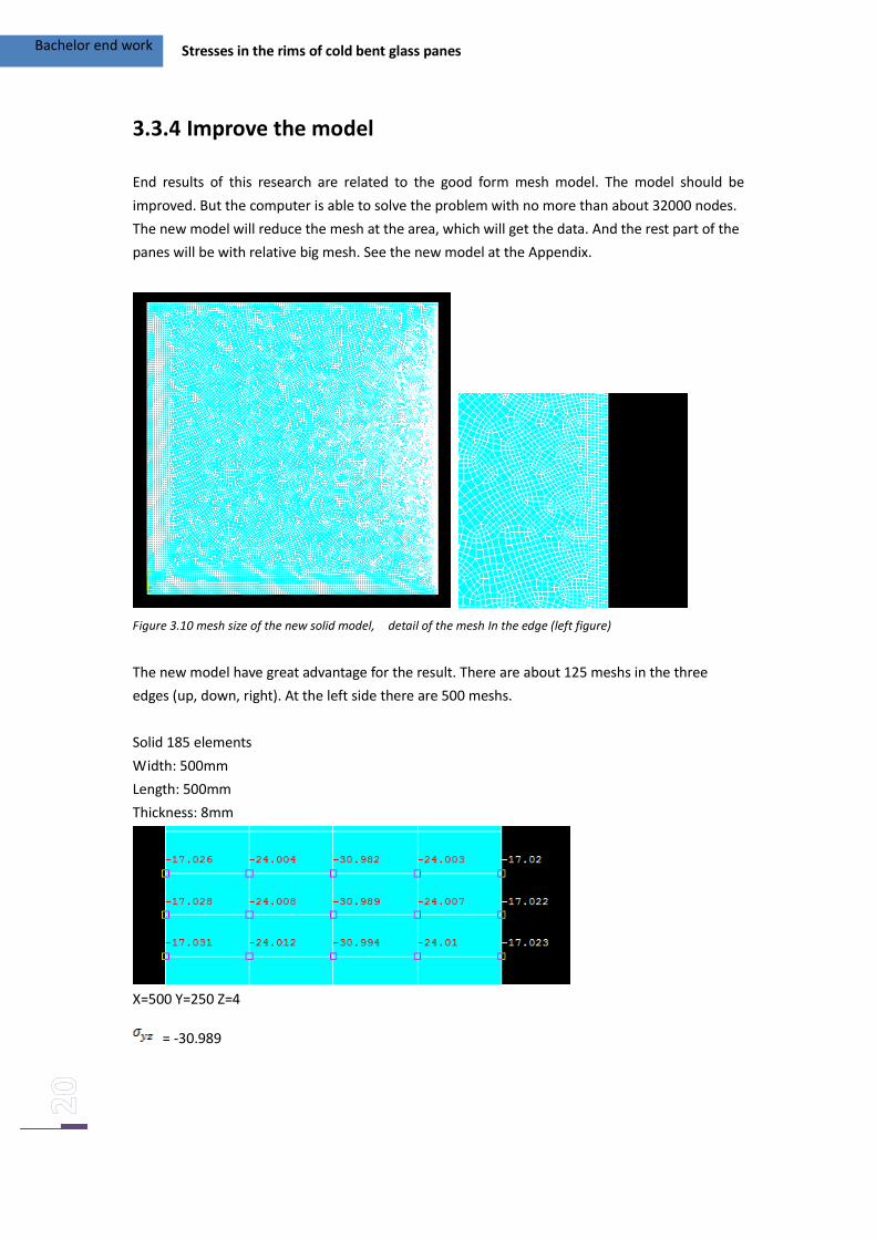
3.3.4 Improve the model
End results of this research are related to the good form mesh model. The model should be
improved. But the computer is able to solve the problem with no more than about 32000 nodes.
The new model will reduce the mesh at the area, which will get the data. And the rest part of the
panes will be with relative big mesh. See the new model at the Appendix.
Figure 3.10 mesh size of the new solid model, detail of the mesh In the edge (left figure)
The new model have great advantage for the result. There are about 125 meshs in the three
edges (up, down, right). At the left side there are 500 meshs.
Solid 185 elements
Width: 500mm
Length: 500mm
Thickness: 8mm
X=500 Y=250 Z=4
= -30.989
Bachelor end work Stresses in the rims of cold bent glass panes
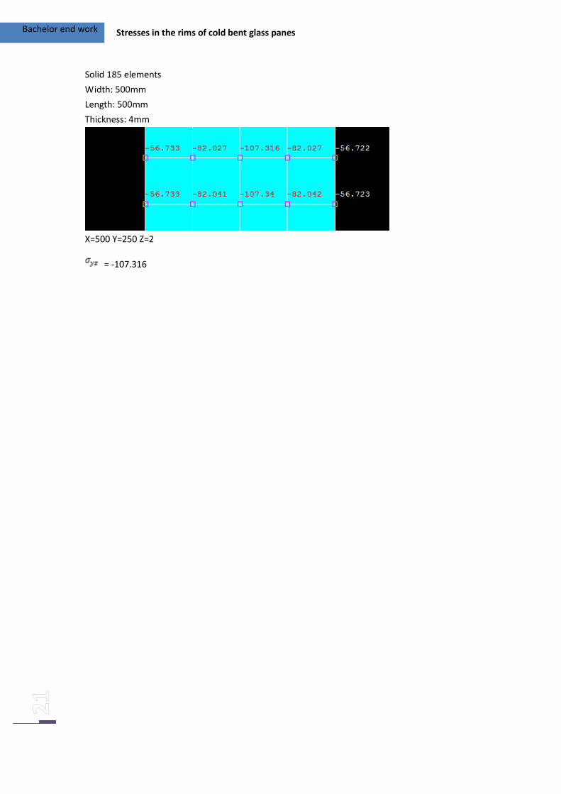
Solid 185 elements
Width: 500mm
Length: 500mm
Thickness: 4mm
X=500 Y=250 Z=2
= -107.316
Bachelor end work Stresses in the rims of cold bent glass panes
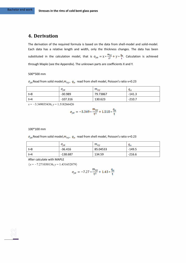
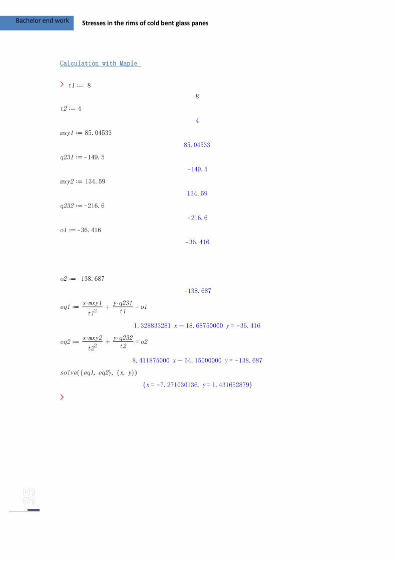
4. Derivation
The derivation of the required formula is based on the data from shell-model and solid-model.
Each data has a relative length and width, only the thickness changes. The data has been
substituted in the calculation model, that is . Calculation is achieved
through Maple (see the Appendix). The unknown parts are coefficients X and Y.
500*500 mm
Read from solid model, , read from shell model, Poisson’s ratio v=0.23
t=8 -30.989 79.73867 -141.3
t=4 -107.316 130.623 -210.7
100*100 mm
Read from solid model, , read from shell model, Poisson’s ratio v=0.23
t=8 -36.416 85.04533 -149.5
t=4 -138.687 134.59 -216.6
After calculate with MAPLE
Bachelor end work Stresses in the rims of cold bent glass panes
5. Alternative derivation
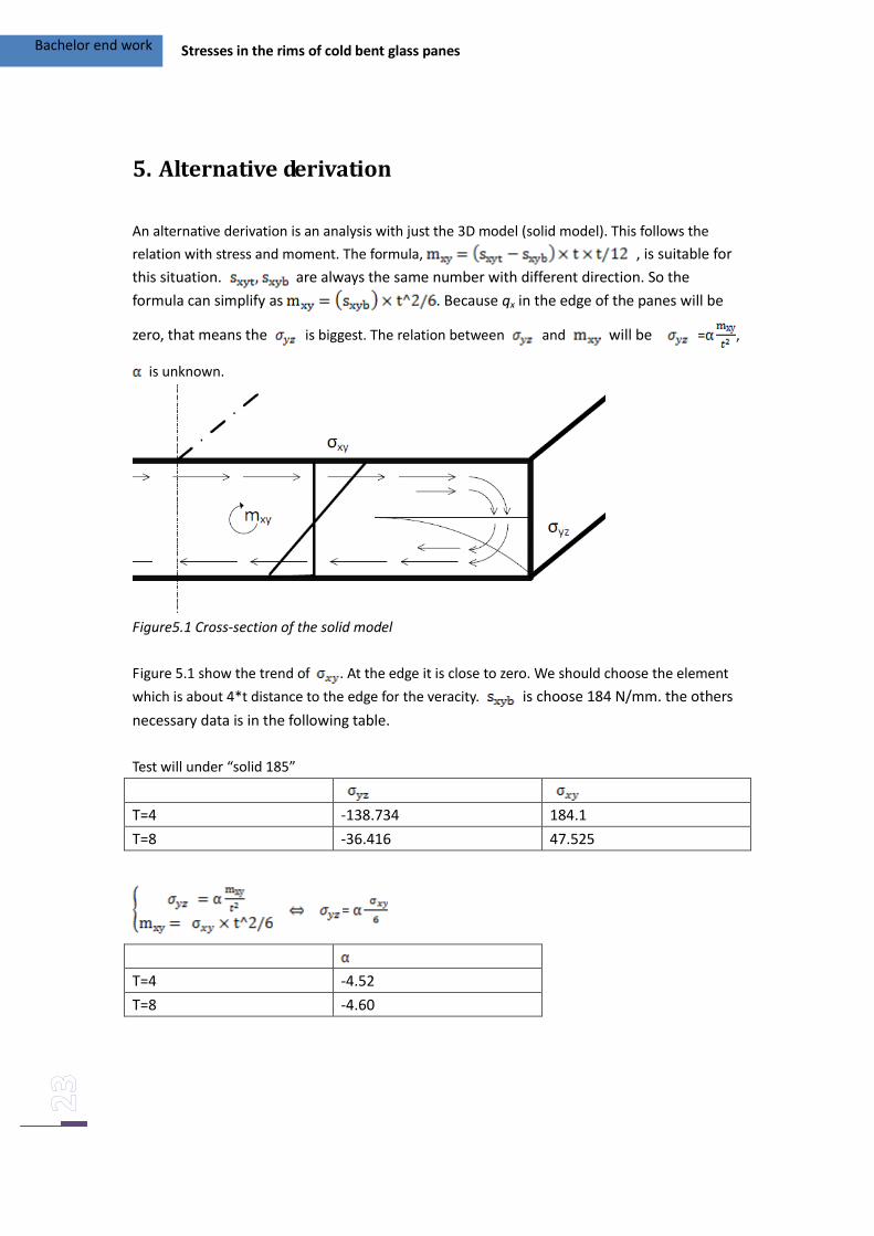
An alternative derivation is an analysis with just the 3D model (solid model). This follows the
relation with stress and moment. The formula, , is suitable for
this situation. are always the same number with different direction. So the
formula can simplify as . Because qx in the edge of the panes will be
zero, that means the is biggest. The relation between and will be = ,
is unknown.
Figure5.1 Cross-section of the solid model
Figure 5.1 show the trend of . At the edge it is close to zero. We should choose the element
which is about 4*t distance to the edge for the veracity. is choose 184 N/mm. the others
necessary data is in the following table.
Test will under “solid 185”
T=4 -138.734 184.1
T=8 -36.416 47.525
=
T=4 -4.52
T=8 -4.60
Bachelor end work Stresses in the rims of cold bent glass panes
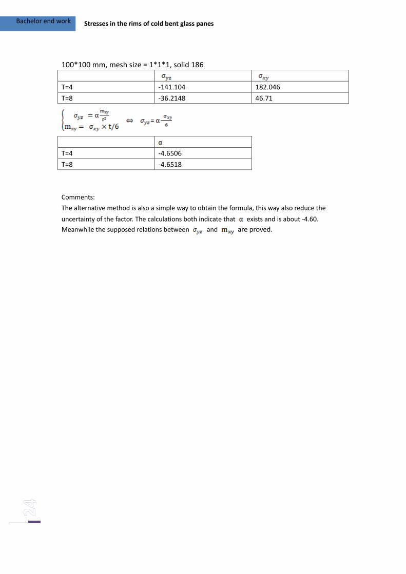
100*100 mm, mesh size = 1*1*1, solid 186
T=4 -141.104 182.046
T=8 -36.2148 46.71
=
T=4 -4.6506
T=8 -4.6518
Comments:
The alternative method is also a simple way to obtain the formula, this way also reduce the
uncertainty of the factor. The calculations both indicate that exists and is about -4.60.
Meanwhile the supposed relations between and are proved.
Bachelor end work Stresses in the rims of cold bent glass panes
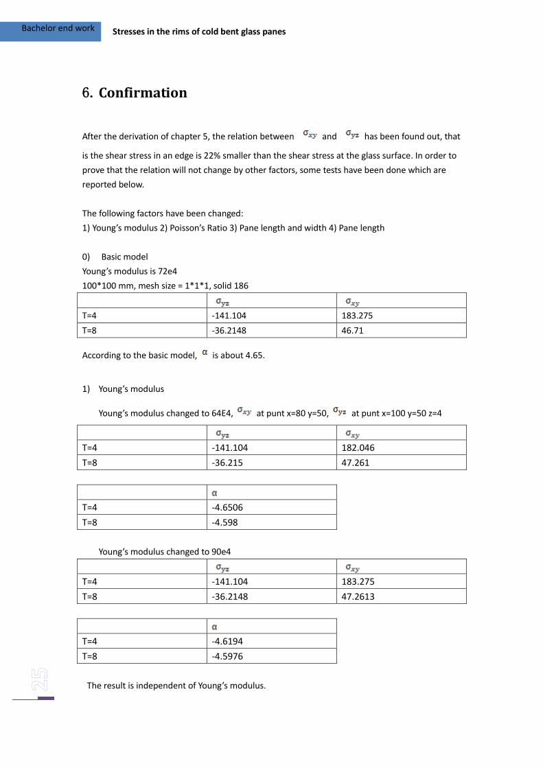
6. Confirmation
After the derivation of chapter 5, the relation between and has been found out, that
is the shear stress in an edge is 22% smaller than the shear stress at the glass surface. In order to
prove that the relation will not change by other factors, some tests have been done which are
reported below.
The following factors have been changed:
1) Young’s modulus 2) Poisson’s Ratio 3) Pane length and width 4) Pane length
0) Basic model
Young’s modulus is 72e4
100*100 mm, mesh size = 1*1*1, solid 186
T=4 -141.104 183.275
T=8 -36.2148 46.71
According to the basic model, is about 4.65.
1) Young’s modulus
Young’s modulus changed to 64E4, at punt x=80 y=50, at punt x=100 y=50 z=4
T=4 -141.104 182.046
T=8 -36.215 47.261
T=4 -4.6506
T=8 -4.598
Young’s modulus changed to 90e4
T=4 -141.104 183.275
T=8 -36.2148 47.2613
T=4 -4.6194
T=8 -4.5976
The result is independent of Young’s modulus.
Bachelor end work Stresses in the rims of cold bent glass panes
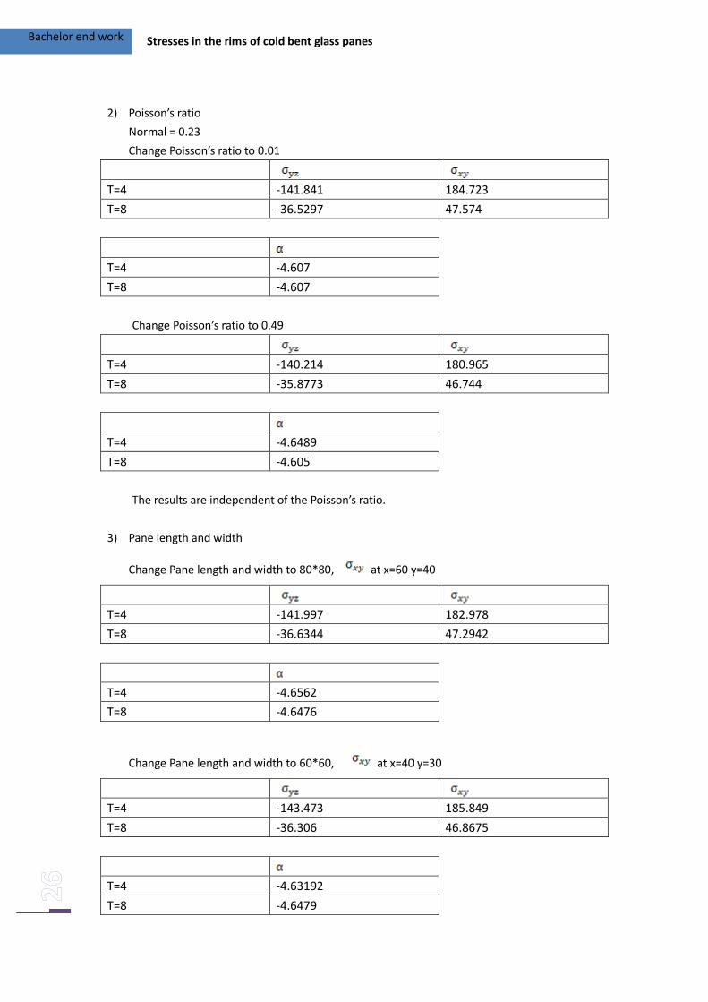
2) Poisson’s ratio
Normal = 0.23
Change Poisson’s ratio to 0.01
T=4 -141.841 184.723
T=8 -36.5297 47.574
T=4 -4.607
T=8 -4.607
Change Poisson’s ratio to 0.49
T=4 -140.214 180.965
T=8 -35.8773 46.744
T=4 -4.6489
T=8 -4.605
The results are independent of the Poisson’s ratio.
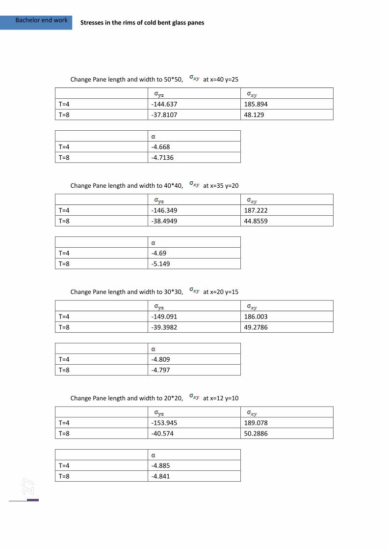
3) Pane length and width
Change Pane length and width to 80*80, at x=60 y=40
T=4 -141.997 182.978
T=8 -36.6344 47.2942
T=4 -4.6562
T=8 -4.6476
Change Pane length and width to 60*60, at x=40 y=30
T=4 -143.473 185.849
T=8 -36.306 46.8675
T=4 -4.63192
T=8 -4.6479
Bachelor end work Stresses in the rims of cold bent glass panes
Change Pane length and width to 50*50, at x=40 y=25
T=4 -144.637 185.894
T=8 -37.8107 48.129
T=4 -4.668
T=8 -4.7136
Change Pane length and width to 40*40, at x=35 y=20
T=4 -146.349 187.222
T=8 -38.4949 44.8559
T=4 -4.69
T=8 -5.149
Change Pane length and width to 30*30, at x=20 y=15
T=4 -149.091 186.003
T=8 -39.3982 49.2786
T=4 -4.809
T=8 -4.797
Change Pane length and width to 20*20, at x=12 y=10
T=4 -153.945 189.078
T=8 -40.574 50.2886
T=4 -4.885
T=8 -4.841
Bachelor end work Stresses in the rims of cold bent glass panes
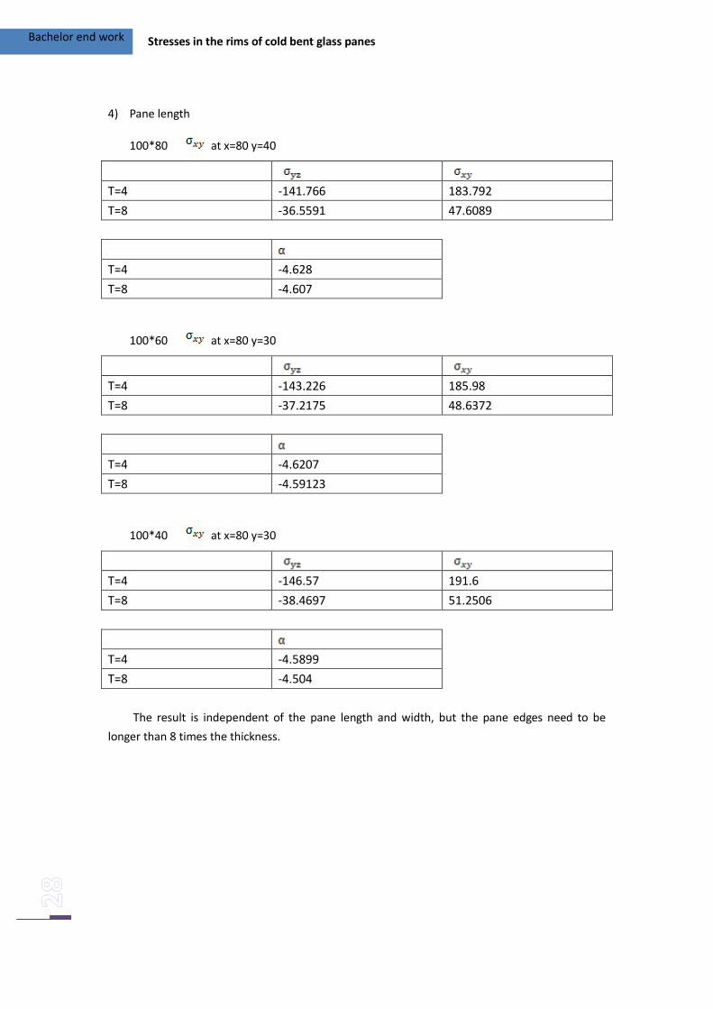
4) Pane length
100*80 at x=80 y=40
T=4 -141.766 183.792
T=8 -36.5591 47.6089
T=4 -4.628
T=8 -4.607
100*60 at x=80 y=30
T=4 -143.226 185.98
T=8 -37.2175 48.6372
T=4 -4.6207
T=8 -4.59123
100*40 at x=80 y=30
T=4 -146.57 191.6
T=8 -38.4697 51.2506
T=4 -4.5899
T=8 -4.504
The result is independent of the pane length and width, but the pane edges need to be
longer than 8 times the thickness.
Bachelor end work Stresses in the rims of cold bent glass panes
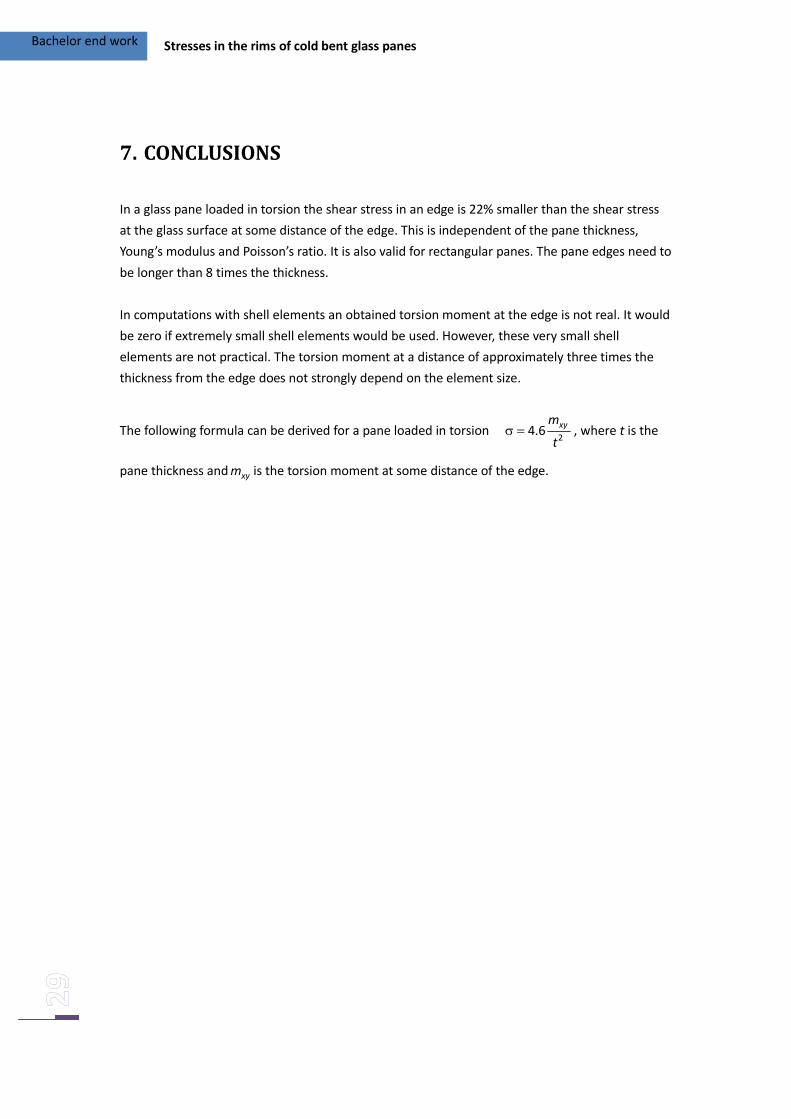
7. CONCLUSIONS
In a glass pane loaded in torsion the shear stress in an edge is 22% smaller than the shear stress
at the glass surface at some distance of the edge. This is independent of the pane thickness,
Young’s modulus and Poisson’s ratio. It is also valid for rectangular panes. The pane edges need to
be longer than 8 times the thickness.
In computations with shell elements an obtained torsion moment at the edge is not real. It would
be zero if extremely small shell elements would be used. However, these very small shell
elements are not practical. The torsion moment at a distance of approximately three times the
thickness from the edge does not strongly depend on the element size.
The following formula can be derived for a pane loaded in torsion .xym
t
24 6 , where t is the
pane thickness and xym is the torsion moment at some distance of the edge.
Bachelor end work Stresses in the rims of cold bent glass panes
8. REFERENCES
[1] M. Eekhout, The New, Cold Bent Glass Roof of the Victoria & Albert Museum, London
http://www.glassglobal.com/gpd/downloads/BuildingProjects-Eekhout.pdf
[2] F.A. Veer, The strength of glass, a nontransparent value, Heron, Vol. 52 (2007) No. 1/2, pp.
87-104.
[3] J. de Wit, Computational modeling of cold bent glass panels, MSc project, Delft University of
Technology, 2009
[4] Ansys help Table 181.3
SOFTWARE
ANSYS Academic Teaching Introductory 11.0 (2011), online, http://www.ansys.com/
Bachelor end work Stresses in the rims of cold bent glass panes
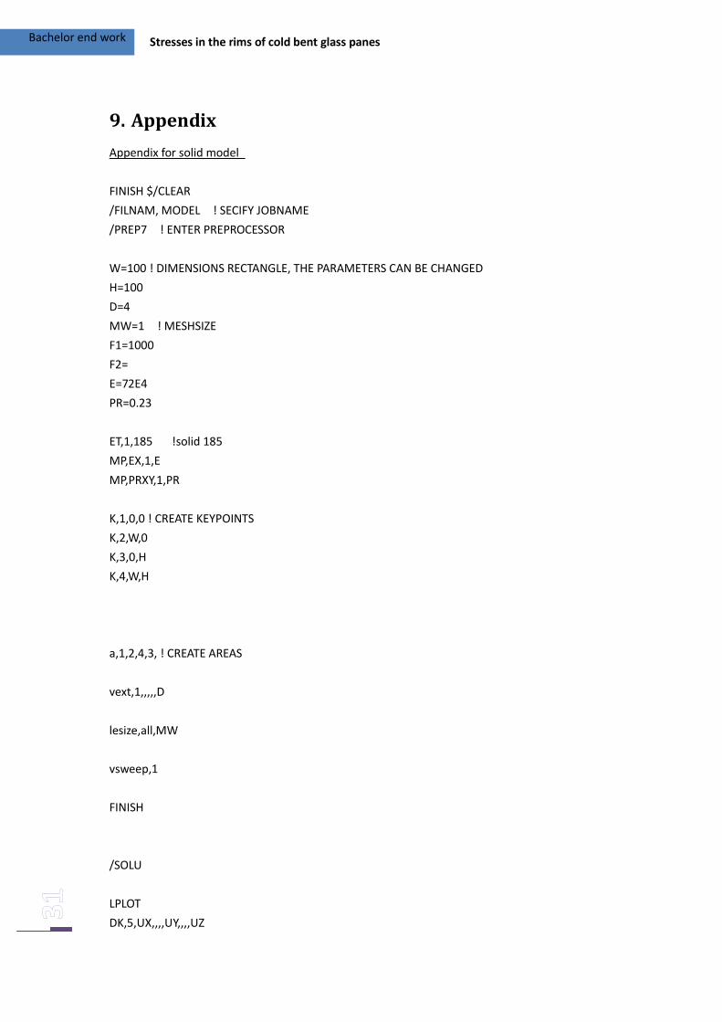
9. Appendix
Appendix for solid model
FINISH $/CLEAR
/FILNAM, MODEL ! SECIFY JOBNAME
/PREP7 ! ENTER PREPROCESSOR
W=100 ! DIMENSIONS RECTANGLE, THE PARAMETERS CAN BE CHANGED
H=100
D=4
MW=1 ! MESHSIZE
F1=1000
F2=
E=72E4
PR=0.23
ET,1,185 !solid 185
MP,EX,1,E
MP,PRXY,1,PR
K,1,0,0 ! CREATE KEYPOINTS
K,2,W,0
K,3,0,H
K,4,W,H
a,1,2,4,3, ! CREATE AREAS
vext,1,,,,,D
lesize,all,MW
vsweep,1
FINISH
/SOLU
LPLOT
DK,5,UX,,,,UY,,,,UZ

Bachelor end work Stresses in the rims of cold bent glass panes
DK,7,UX,,,,UY,,,,UZ
DK,8,UX,,,,UY,,,,UZ
FK,6,FZ,F1
SOLVE
FINISH
Bachelor end work Stresses in the rims of cold bent glass panes
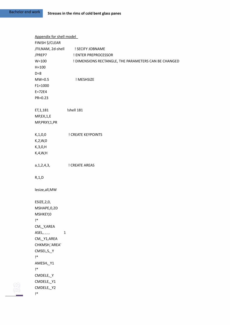
Appendix for shell model
FINISH $/CLEAR
/FILNAM, 2d-shell ! SECIFY JOBNAME
/PREP7 ! ENTER PREPROCESSOR
W=100 ! DIMENSIONS RECTANGLE, THE PARAMETERS CAN BE CHANGED
H=100
D=8
MW=0.5 ! MESHSIZE
F1=1000
E=72E4
PR=0.23
ET,1,181 !shell 181
MP,EX,1,E
MP,PRXY,1,PR
K,1,0,0 ! CREATE KEYPOINTS
K,2,W,0
K,3,0,H
K,4,W,H
a,1,2,4,3, ! CREATE AREAS
R,1,D
lesize,all,MW
ESIZE,2,0,
MSHAPE,0,2D
MSHKEY,0
!*
CM,_Y,AREA
ASEL, , , , 1
CM,_Y1,AREA
CHKMSH,'AREA'
CMSEL,S,_Y
!*
AMESH,_Y1
!*
CMDELE,_Y
CMDELE,_Y1
CMDELE,_Y2
!*
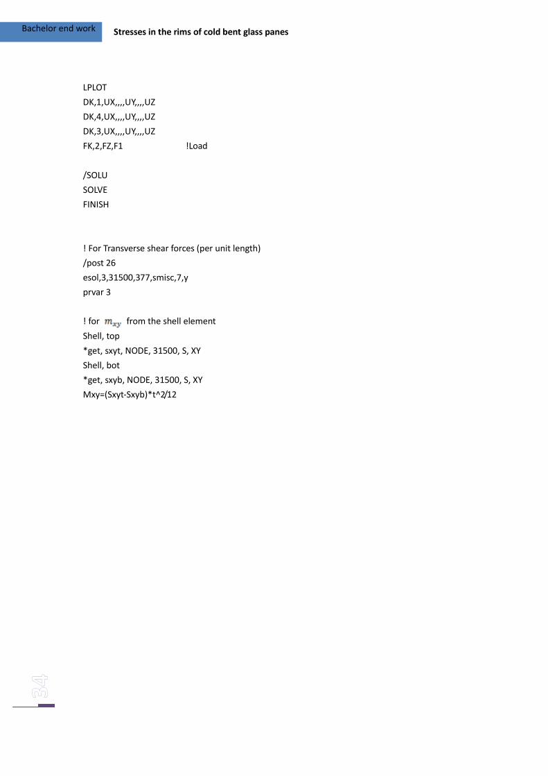
Bachelor end work Stresses in the rims of cold bent glass panes
LPLOT
DK,1,UX,,,,UY,,,,UZ
DK,4,UX,,,,UY,,,,UZ
DK,3,UX,,,,UY,,,,UZ
FK,2,FZ,F1 !Load
/SOLU
SOLVE
FINISH
! For Transverse shear forces (per unit length)
/post 26
esol,3,31500,377,smisc,7,y
prvar 3
! for from the shell element
Shell, top
*get, sxyt, NODE, 31500, S, XY
Shell, bot
*get, sxyb, NODE, 31500, S, XY
Mxy=(Sxyt-Sxyb)*t^2/12
Bachelor end work Stresses in the rims of cold bent glass panes
Calculation with Maple
>
>
Bachelor end work Stresses in the rims of cold bent glass panes
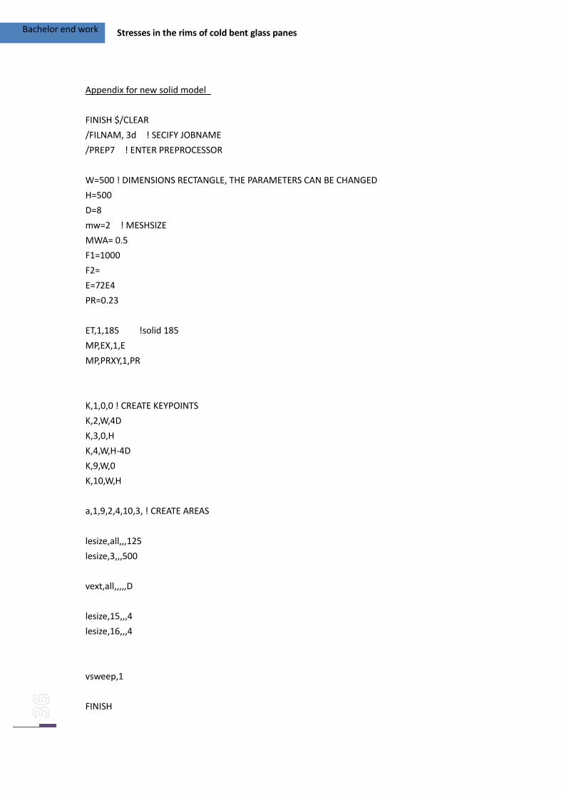
Appendix for new solid model
FINISH $/CLEAR
/FILNAM, 3d ! SECIFY JOBNAME
/PREP7 ! ENTER PREPROCESSOR
W=500 ! DIMENSIONS RECTANGLE, THE PARAMETERS CAN BE CHANGED
H=500
D=8
mw=2 ! MESHSIZE
MWA= 0.5
F1=1000
F2=
E=72E4
PR=0.23
ET,1,185 !solid 185
MP,EX,1,E
MP,PRXY,1,PR
K,1,0,0 ! CREATE KEYPOINTS
K,2,W,4D
K,3,0,H
K,4,W,H-4D
K,9,W,0
K,10,W,H
a,1,9,2,4,10,3, ! CREATE AREAS
lesize,all,,,125
lesize,3,,,500
vext,all,,,,,D
lesize,15,,,4
lesize,16,,,4
vsweep,1
FINISH

Bachelor end work Stresses in the rims of cold bent glass panes
/SOLU
LPLOT
DK,10,UX,,,,UY,,,,UZ
DK,3,UX,,,,UY,,,,UZ
DK,1,UX,,,,UY,,,,UZ
FK,9,FZ,F1
SOLVE
FINISH