Embed Size (px)
Citation preview
Stress transformation:tractors, linear algebra, and circles within circles.
Henri P. Gavin
EGR 201L.Intro Solid Mechanics
Department of Civil & Environmental EngineeringDuke University
Spring 2017

traction is stress at a point on a plane

Sunday! SUNDAY!! SUNDAY!!!
Stress Transformation tractors EGR 201L. Duke H.P.G Spring 2017 1 / 36

traction forces in equilibrium
Stress Transformation tractors EGR 201L. Duke H.P.G Spring 2017 2 / 36

nonuniform distribution of traction stress components
σ(x)
τ(x)Stress Transformation tractors EGR 201L. Duke H.P.G Spring 2017 3 / 36

a small volume under traction stress vectors,~tx ,~ty
x
y
z
σ
σ
∆A
ty
tx
∆A
yy
xx
τxy
yxτ
I Traction is a stress vector acting on a plane.I The traction stress vector~tx acts on the x-normal plane and
has components σxx and τxy .
I The traction stress vector~ty acts on the y-normal plane andhas components τyx and σyy .
Stress Transformation tractors EGR 201L. Duke H.P.G Spring 2017 4 / 36

the state of stress is coordinate invariant

the state of stress in 2D
I The state of stress on an infinitesimal cubic volume is completelydescribed by the traction vectors acting on the faces of the cube.
I In 2D (plane stress), the complete set of traction stresses is
S =
[~tx~ty
]=
[σxx τxy
τyx σyy
]I S is called the stress tensorI τxy = τyx ... S is a symmetric tensor
σ
σ
σ
σ
dl
dl
Pxx
xx
yy
yy
xyτ
yxτ
τxy
yxτ
∑MP = 0 :
+σxx(∆A)(dl/2) − σxx(∆A)(dl/2)
+σyy(∆A)(dl/2) − σyy(∆A)(dl/2)
+τxy(∆A)(dl) − τyx(∆A)(dl) = 0
Stress Transformation 2D stress EGR 201L. Duke H.P.G Spring 2017 5 / 36

traction stress vectors on coordinate planesI The traction stress vector~tx is the first row of S.
~tx = [1 0] ·
[σxx τxy
τyx σyy
]= ~ı · S
Note: ~ı is the unit normal to the x-plane.I The traction stress vector~ty is the second row of S.
~ty = [0 1] ·
[σxx τxy
τyx σyy
]= ~ · S
Note: ~ is the unit normal to the y-plane.I Just as~tx = ~ı · S and~ty = ~ · S, the stress vector on any other plane
(with unit normal ~n) is given by
~tn = ~n · S
This is what the stress tensor does.It defines tractions on any plane.
Stress Transformation 2D stress EGR 201L. Duke H.P.G Spring 2017 6 / 36

traction stress vectors on any plane: ~tn = ~n · S
x
y
σ
σ
A sin
A c
os
θ
θ
θ
θ
A
xttn
n
ty
tx
ty
yxτ
xx
xyτ
yy
equilibrium on the wedge:
A~tn = (A cos θ)~tx+(A sin θ)~ty
~tn = [cos θ sin θ] ·
[~tx~ty
]~n = [cos θ sin θ]
S =
[~tx~ty
]~tn = ~n · S
The traction~tn = ~n · S is expressed in the xy coordinate system.
note: (A cos θ) = Anx and (A sin θ) = Any
Stress Transformation 2D stress EGR 201L. Duke H.P.G Spring 2017 7 / 36

traction stress vectors in other coordinates: ~t ′n = ~tn · TI Let’s express this traction~tn in a new coordinate system x′y′,
where x′ is along the unit normal ~n and y′ is perpendicular to x′.I These rotated components of~tn are the normal stress and shear
stress on the plane with normal ~n: t ′n = [σx′x′ , τx′y′ ]
y
x
σ
n
t
t tn
nx
ny
x’x’
y’
x’x’y’τ
c = cos θ
s = sin θ
σx′x′ = tnxc + tnys
τx′y′ = −tnxs + tnyc
[σx′x′ , τx′y′
]=
[tnx , tny
] [ c −ss c
]; ~t ′n = ~tn · T ; T−1 = TT
Stress Transformation 2D stress EGR 201L. Duke H.P.G Spring 2017 8 / 36
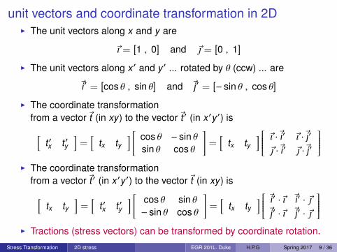
unit vectors and coordinate transformation in 2DI The unit vectors along x and y are
~ı = [1 , 0] and ~ = [0 , 1]
I The unit vectors along x′ and y′ ... rotated by θ (ccw) ... are
~i′ = [cos θ , sin θ] and ~j′ = [− sin θ , cos θ]
I The coordinate transformationfrom a vector~t (in xy) to the vector~t ′ (in x′y′) is[
t ′x t ′y]
=[
tx ty] [ cos θ − sin θ
sin θ cos θ
]=
[tx ty
] ~ı ·~i′ ~ı ·~j′
~ ·~i′ ~ ·~j′
I The coordinate transformation
from a vector~t ′ (in x′y′) to the vector~t (in xy) is[tx ty
]=
[t ′x t ′y
] [ cos θ sin θ− sin θ cos θ
]=
[tx ty
] ~i′ ·~ı ~i′ · ~~j′ ·~ı ~j′ · ~
I Tractions (stress vectors) can be transformed by coordinate rotation.
Stress Transformation 2D stress EGR 201L. Duke H.P.G Spring 2017 9 / 36

summary
x
y
σ
σ
A sin
A c
os
θ
θ
θ
θ
A
xttn
n
ty
tx
ty
yxτ
xx
xyτ
yy
y
x
σ
n
t
t tn
nx
ny
x’x’
y’
x’x’y’τ
I In the xy coordinate system, thetraction on a plane with unitnormal n is
~tn = ~n · S
= [cos θ , sin θ] · S
I The coordinate transformationfrom~tn (in xy) to~t ′n (in x′y′) is
~t ′n = ~tn · T
I Unit vectors can be similarlytransformed, ~n′ = ~n · T ... and ...
~n = ~n′ · TT
[cos θ , sin θ] = [1 , 0] · TT
Stress Transformation 2D stress EGR 201L. Duke H.P.G Spring 2017 10 / 36

putting it all together ... stress transformationI Given:
• stress in an xy coordinate system, S.• a unit vector ~n along x′ in an x′y′ coordinate system.
I Find: The stress S′ in the x′y′ coordinate system.I Substitute ...
~t ′n = ~tn · T~t ′n = ~n · S · T~t ′n = ~n′ · TT · S · T~t ′n = ~n′ · S′
S′ = TT · S · T
In 2D, the stress transformation formula for a CCW rotation θ is:[σx′x′ τx′y′
τy′x′ σy′y′
]=
[c s−s c
] [σxx τxy
τyx σyy
] [c −ss c
]Stress Transformation 2D stress EGR 201L. Duke H.P.G Spring 2017 11 / 36
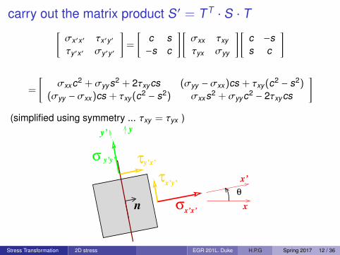
carry out the matrix product S ′ = TT · S · T[σx′x′ τx′y′
τy′x′ σy′y′
]=
[c s−s c
] [σxx τxy
τyx σyy
] [c −ss c
]
=
[σxxc2 + σyys2 + 2τxycs (σyy − σxx)cs + τxy(c2 − s2)
(σyy − σxx)cs + τxy(c2 − s2) σxxs2 + σyyc2 − 2τxycs
](simplified using symmetry ... τxy = τyx )
x
x’
yy’
σ
σ
θ
n
τ
τx’y’
y’x’y’y’
x’x’
Stress Transformation 2D stress EGR 201L. Duke H.P.G Spring 2017 12 / 36

For what angle θ is τx′y′ = 0?1. On what planes is the shear stress zero?2. What is the transformation matrix T that diagonalizes S′?3. What are the normal stresses on planes with no shear stress?[
c s−s c
] [σxx τxy
τyx σyy
] [c −ss c
]=
[σ1 00 σ2
][
c s−s c
] [σxx τxy
τyx σyy
]=
[σ1 00 σ2
] [c s−s c
][
c s] [ σxx τxy
τyx σyy
]= σ1
[c s
][−s c
] [ σxx τxy
τyx σyy
]= σ2
[−s c
]1. Planes with no shear stress are normal to eigenvectors of S.2. The transformation matrix T of eigenvectors of S diagonalizes S.3. The normal stresses on planes with no shear stress are the
eigenvalues of S, σ1 and σ2. These are called principle stresses.Stress Transformation 2D stress EGR 201L. Duke H.P.G Spring 2017 13 / 36

principle stresses are the eigenvalues of the stress tensorThat sounds impressive.But what does it mean?Let’s look at an example in 2D.
S =
[~tx~ty
]=
[σxx τxy
τyx σyy
]=
[2 −5−5 4
]kPa
Here’s a plot of~tn(θ) = ~n(θ) · S for all values of ~n(θ) = [cos θ , sin θ]
-10
-5
0
5
10
-10 -5 0 5 10
ny ,
txy
nx , txx
n(θ)
tn(θ)
σ1=-2.10 kPa
σ2= 8.10 kPa
tn(0)
Stress Transformation 2D stress EGR 201L. Duke H.P.G Spring 2017 14 / 36

principle stresses are the eigenvalues of the stress tensor
-10
-5
0
5
10
-10 -5 0 5 10
ny ,
txy
nx , txx
n(θ)
tn(θ)
σ1=-2.10 kPa
σ2= 8.10 kPa
tn(0)
I At θ = 0, ~n(θ) = [1 , 0] and~tn = ~tx = [S11,S12] = [2,−5]I In general, the traction vector is not in line with the normal vector.I There are two normal vectors for which the traction vectors align with
the normal vector. These are the eigenvectors of S.I For normal vectors aligned with the eigenvectors of S, the traction
vector~tn is in line with the normal vector ~n, and has a length equal tothe eigenvalues of S. These are the principal stresses. (red lines).
Stress Transformation 2D stress EGR 201L. Duke H.P.G Spring 2017 15 / 36

Mohr’s Circle (for plane stress)

trigonometry and algebra lead to Mohr’s circleSubstitute:
cos2 θ = (1 + cos 2θ)/2
sin2 θ = (1 − cos 2θ)/2
2 sin θ cos θ = sin 2θ
into:σx′x′ = σxx cos2 θ + σyy sin2 θ + 2τxy sin θ cos θ
τx′y′ = (σyy − σxx) sin θ cos θ + τxy(cos2 θ − sin2 θ)
square equations, add them, and do some algebra to obtain:(σx′x′ −
σxx + σyy
2
)2
+ τ2x′y′ =
(σxx − σyy
2
)2+ τ2
xy
and compare to:(x − c)2 + y2 = r2
to recognize the equation for a circle with center (c, 0) and radius r !Stress Transformation 2D Mohr’s circle EGR 201L. Duke H.P.G Spring 2017 16 / 36

Mohr’s circle of stressI The center of Mohr’s circle is at
(σxx +σyy
2 , 0)
.I The radius of Mohr’s circle is the maximum shear stress, τmax
τmax =
[(σxx − σyy
2
)2+ τ2
xy
] 12
I There exists a plane on which the shear stresses are zero. This planeis inclined at an angle α from the xy axes. The normal stresses actingat this orientation are called the principle stresses, σ1 and σ2.
I From Mohr’s circle:
σ1 =σxx + σyy
2+ τmax σ2 =
σxx + σyy
2− τmax
I The angle, α, is given by:
2α = arctan(
2τxy
σxx − σyy
)Stress Transformation 2D Mohr’s circle EGR 201L. Duke H.P.G Spring 2017 17 / 36

Mohr’s Circle Procedure - draw the circle
1. Draw the stress element aligned with the original x, y axes.Show the known stresses, σxx , σyy , and τxy on the stress element.Tension is positive.Compression is negative.
2. Draw the σ, τ axes for Mohr’s circle with τ pointing down.
3. Locate the center C of the circle at(σxx +σyy
2 , 0).
4. Locate the point X on the circle at (σxx , τxy).
5. Draw the circle passing through point X with center at point C.The circle will pass through point Y (σyy ,−τxy) 180 degrees frompoint X .
Stress Transformation 2D Mohr’s circle EGR 201L. Duke H.P.G Spring 2017 18 / 36

Mohr’s Circle Procedure - draw the circle
yy xy(σ ,−τ )
xyxx(σ , τ )
x
y
ασ2
σ1 σ
τmax
τ
Y
2α
X
Stress Transformation 2D Mohr’s circle EGR 201L. Duke H.P.G Spring 2017 19 / 36

Mohr’s Circle Procedure - transform the stress
1. Draw new axes x′y′ rotated an angle θ counter-clockwise from the xyaxes on the stress element from step 1a above.
2. Find numerical values for the principle stresses, the maximum shearstresses, and the angle, α, from the xy axes to the principle axes.
3. Separate the angle θ into two parts: θ = α + β.
4. Calculate the new stresses:
σx′x′ =σxx + σyy
2+ τmax cos(−2β)
σy′y′ =σxx + σyy
2− τmax cos(−2β)
τx′y′ = τmax sin(−2β)
5. Points X ′, (σx′x′ , τx′y′) and Y ′, (σy′y′ ,−τx′y′) lie on the circle at anangle 2θ in the CCW direction from points X and Y , respectively.
Is this easier than S′ = TT · S · T ?Stress Transformation 2D Mohr’s circle EGR 201L. Duke H.P.G Spring 2017 20 / 36

Mohr’s Circle Procedure - transform the stress
xyxx(σ , τ )
x’y’x’x’(σ , τ )
yy xy(σ ,−τ )
y’y’ x’y’(σ , −τ )
x’y’
θ
x
y
ασ2
σ12α
2θ
2β
X’
Y
Y’X
maxτ
σ
τ
Stress Transformation 2D Mohr’s circle EGR 201L. Duke H.P.G Spring 2017 21 / 36

notes on Mohr’s circleI Why is a counter-clockwise rotation of the coordinate axes translated
into a counter-clock-wise rotation on Mohr’s circle?I Why are the rotations of the coordinate axes doubled when translated
to Mohr’s circle?
The answer to these questions can be answered by considering the stateof stress caused by pure torsion:
α
(σ ,−τ )yy xy
(σ , τ )xx xy
x
y
σσ 2 1σ
τmaxτy
2α
Y’
Y
X’
X
Stress Transformation 2D Mohr’s circle EGR 201L. Duke H.P.G Spring 2017 22 / 36

notes on Mohr’s circle
I This state of stress is described by a Mohr’s circle centered at theorigin of the σ − τ axes with a radius equal to τ̄.
I Points X and Y lie on the τ-axisI Point X is located at (0,+τ̄).
Point Y is located at (0,−τ̄).I If a new set of axes (x′y′) are drawn at an angle of 45 degrees
(CCW) to the xy axes, no shear stresses will act on surfaces normalto the x′y′ axes.
I The normal stress acting along the x′-axis will be in tension. Thenormal stress acting along the y′-axis will be in compression.
I These stresses correspond to points X ′ and Y ′, rotated in a CCWdirection of 90 degrees from points X and Y , respectively.
I Point X ′ shows a tensile stress +τ̄.Point Y ′ shows a compressive stress −τ̄.
Stress Transformation 2D Mohr’s circle EGR 201L. Duke H.P.G Spring 2017 23 / 36

So what’s easier, Mohr’s Circle or S ′ = TT · S · T ?
S = [ 2 -5 ; % 2D stress tensor
-5 4 ];
[ evecS , evalS ] = eig(S) % principle directions & stresses
tau_max = (max(diag(evalS)) - min(diag(evalS)))/2
t = 47; % rotation angle theta (degrees)
T = [ cosd(t) , -sind(t) ; % coordinate transformation matx
sind(t) , cosd(t) ];
St = T’*S*T % transformed stress tensor
... you may decide for yourself.It’s good to know about Linear Algebra.
Stress Transformation 2D Mohr’s circle EGR 201L. Duke H.P.G Spring 2017 24 / 36

stress transformation in 3D

the continuum potato
cuts on three planes (yz, zx, zy)and an internal elemental cube with surface areas ∆A .
y
x
z
xy
xz
yz
Stress Transformation 3D stress EGR 201L. Duke H.P.G Spring 2017 25 / 36

The elemental stress cubeshowing “positive-facing” faces
z
x
y
τ
σ
σ
σ
zz
τ
τzy
τ
xx
yy
xz
τ yx
yz
τzx
τxy
σii = lim∆A→0
∆Nii
∆Ai
τij = lim∆A→0
∆Vij
∆Ai
S =
σxx τxy τxz
τyx σyy τyz
τzx τzy σzz
Stress Transformation 3D stress EGR 201L. Duke H.P.G Spring 2017 26 / 36
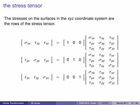
the stress tensor
The stresses on the surfaces in the xyz coordinate system arethe rows of the stress tensor.
[σxx τxy τxz
]=
[1 0 0
] σxx τxy τxz
τyx σyy τyz
τzx τzy σzz
[τyx σyy τyz
]=
[0 1 0
] σxx τxy τxz
τyx σyy τyz
τzx τzy σzz
[τzx τzy σzz
]=
[0 0 1
] σxx τxy τxz
τyx σyy τyz
τzx τzy σzz
Stress Transformation 3D stress EGR 201L. Duke H.P.G Spring 2017 27 / 36
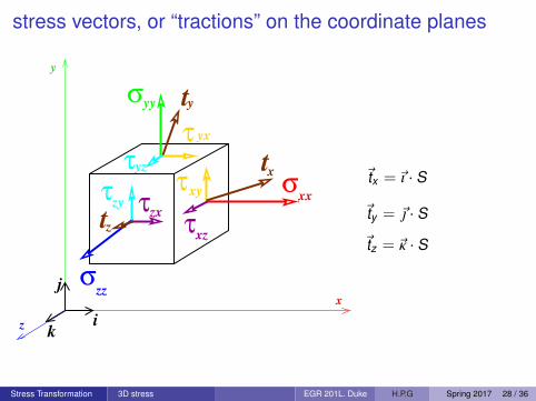
stress vectors, or “tractions” on the coordinate planes
z
x
y
i
j
k
τ
σ
σ
σ t
zz
τ
τzy
τ
xx
yy
xz
τ yx
yz
τzx
τxy
x
y
t
tz
~tx = ~ı · S
~ty = ~ · S
~tz = ~κ · S
Stress Transformation 3D stress EGR 201L. Duke H.P.G Spring 2017 28 / 36

stress vectors, or “tractions” on the coordinate planesThe traction,~t , on a surface has xyz components.The traction on the surface with unit normal~ı is
~tx = σxx~ı + τxy~+ τxz~k =[σxx τxy τxz
]= ~ı · S
The traction on the surface with unit normal ~ is
~ty = τyx~ı + σyy~+ τyz~κ =[τyx σyy τyz
]= ~ · S
The traction on the surface with unit normal ~κ is
~tz = τzx~ı + τzy~+ σzz~κ =[τzx τzy σzz
]= ~κ · S
Likewise ... (because the stress tensor is a linear operator)The traction on any surface with unit normal ~n is
~tn = ~n · S
Stress Transformation 3D stress EGR 201L. Duke H.P.G Spring 2017 29 / 36
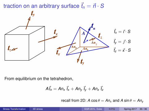
traction on an arbitrary surface~tn = ~n · St
An
Anz
y
A
Anx
x
y
t
tz t
tx
y
tz
nt
~tx = ~ı · S
~ty = ~ · S
~tz = ~κ · S
From equilibrium on the tetrahedron,
A~tn = Anx ~tx + Any ~ty + Anz ~tz
recall from 2D: A cos θ = Anx and A sin θ = Any
Stress Transformation 3D stress EGR 201L. Duke H.P.G Spring 2017 30 / 36

traction on an arbitrary surface~tn = ~n · S
I Consider the three coordinate planes passing through a point withunit normal vectors~ı, ~, and ~κ
I The unit normal vector ~n to any plane can be expressed in terms of~ı,~, and ~κ.
~n = nx ~ı + ny ~+ nz ~κ
I From equilibrium on the tetrahedron:
~tn = nx ~tx + ny ~ty + nz ~tz
I So the traction~tn on a plane with unit normal ~n
~tn = nx~ı · S + ny~ · S + nz~κ · S = (nx~ı + ny~+ nz~κ) · S = ~n · S
Stress Transformation 3D stress EGR 201L. Duke H.P.G Spring 2017 31 / 36

traction stress vectors in other coordinates: ~t ′n = ~tn · T
I Let’s express this traction~tn in a new coordinate system x′y′z′ where~ı, ~,~κ are unit vectors in the x, y, z axes, and~i′,~j′, ~k ′ are unit vectors in the x′, y′, z′ axes.
I These rotated components of~tn are the normal stress and shearstress in the rotated coordinate system : t ′n = [σx′x′ , τx′y′ , τx′z′ ]
y’ y
x’y’
x’
x
τ
z’
τx’z’
i
j
k
i’j’
k’
x’x’σ
nx
nz
t
t
tz
tnny ~t ′n = ~tn · T
T =
~ı ·~i′ ~ı ·~j′ ~ı · ~k ′
~ ·~i′ ~ ·~j′ ~ · ~k ′
~κ ·~i′ ~κ ·~j′ ~κ · ~k ′
T−1 = TT
recall coordinate transformation matrix in 2D
Stress Transformation 3D stress EGR 201L. Duke H.P.G Spring 2017 32 / 36

transformation of tractions and stresses

apply coordinate transformation to a tractionI the traction on surface “n” is
... ~tn = ~n · SI the coordinate transformation from unit normal ~n′ to unit normal ~n is
... ~n = ~n′ · TT
I the coordinate transformation from traction vectors~tn to~t ′n is... ~t ′n = ~tn · T
~t ′n = ~tn · T
= ~n · S · T
= ~n′ · TT · S · T
= ~n′ · (TT · S · T)
= ~n′ · S′
So, the stress tensor S ’ in a coordinate system with axis ~n′ can beexpressed in terms of the stress tensor S in a coordinate system with axis~n where ~n′ = ~n · T ,
S′ = TT · S · TStress Transformation 3D stress transformation EGR 201L. Duke H.P.G Spring 2017 33 / 36

Mohr’s circle in 3D

Mohr’s circle in 3D
I Make three Mohr’s circles,• one for the xy stress square,• one for the yz stress square, and• one for the xz stress square.
I The three circles will share three principle stresses.
I If there is no traction on one face of the stress cube,then then one of the principle stresses is zero.In this case:• If σ1 > 0 and σ2 < 0, then τmax = (σ1 − σ2)/2• If σ1 > 0 and σ2 > 0, then τmax = +σ1/2• If σ1 < 0 and σ2 < 0, then τmax = −σ2/2
Stress Transformation 3D Mohr’s circle EGR 201L. Duke H.P.G Spring 2017 34 / 36
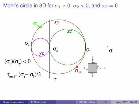
Mohr’s circle in 3D for σ1 > 0, σ2 < 0, and σ3 = 0
max 1τ = (σ − σ )/2
2
σ2
σ1 σσ3
τ
σyy
xxσ
(σ )(σ ) < 01 2
yz
xz
xy
x
y
Stress Transformation 3D Mohr’s circle EGR 201L. Duke H.P.G Spring 2017 35 / 36

Mohr’s circle in 3D for σ1 > 0, σ2 > 0, and σ3 = 0
τ = σ /21max
1σ
3σσ
2
σ
(σ )(σ ) > 01 2
τ
xy
xz
yz
x
y
What are the 3D coordinate rotationsto get from the x, y, z coordinates to the τmax coordinates?
... (α about z, 45 deg. about y′).Biaxial tension: ductile shear failure. Triaxial tension: brittle tensile failure.
Stress Transformation 3D Mohr’s circle EGR 201L. Duke H.P.G Spring 2017 36 / 36