Embed Size (px)
Citation preview

This material is declared a work of the U.S. Government and is not subject to copyright protection in the United States. Approved for public release; distribution is unlimited.
1
Proceedings of the ASME 2019 Pressure Vessels & Piping Conference
PVP2019 July 14-19, 2019, San Antonio, TX, USA
STRESS INTENSITY FACTORS FOR LAYERED PRESSURE VESSEL INNER LAYER THROUGH CRACKS
Joel R. Hobbs1 NASA, Marshall Space Flight Center
Huntsville, AL, USA
ABSTRACT A difficulty encountered when performing Fitness-for-
Service assessments for layered pressure vessels (LPVs) is the lack of stress intensity factor solution in literature that produce accurate results for inner layer longitudinal through cracks. Using surrogate solutions such as a through crack in a plate or cylinder produce results that can be overly conservative especially for longer cracks. This is largely due to the ability of a layered pressure vessel to redistribute hoop load to other layers, the restricted radial movement of the cracked layer, and the friction forces applied in the cracked region.
To understand this problem, a parametric finite element model (FEM) generator was developed that is capable of producing layered pressure vessel models with inner layer through cracks. The results from the FEMs were used to create a dataset of inner layer through crack stress intensity factors (KI) for layered pressure vessels corresponding to variations of internal pressure, radius, layer thicknesses, friction factor, and crack length. The elastic modulus of the material also has an effect on KI but, for this dataset, the elastic modulus was fixed at the typical value for steel - 29,500 ksi (203 GPa).
Finally, a non-dimensional model was developed and calibrated using the dataset. This allows KI to be calculated without the need of a FEM using a closed-form equation. The results of the closed-form solution were then compared to FEM results showing accuracy was generally within 10%.
NOMENCLATURE α dimensionless term for frictionless model β stress correction non-dimensional term c half crack length Ɣ boundary correction factor
1 Contact author: [email protected]
Ɣfrictionless correction factor for frictionless model Ɣfriction correction factor for friction model E elastic modulus FEA finite element analysis FEM finite element model ILLTC inner layer longitudinal through crack KI stress intensity factor LPV layered pressure vessel MLTC monocoque longitudinal through crack µ static friction factor ν Poisson’s ratio ∏1 dimensionless term for friction model R inner layer middle radius r inner layer external radius ri internal radius ro external radius t total shell thickness t1 inner layer thickness t2 total wrapper layer thicknesses
INTRODUCTION The National Aeronautics and Space Administration (NASA) has a large fleet of layered pressure vessels (LPVs) currently in use, most built in the 1960's before design and construction standards were incorporated into the ASME Boiler and Pressure Vessel Code [1]. To insure continued safe operation (Fitness-for-Service) of these vessels, a comprehensive effort has been undertaken by NASA to develop an understanding of the behavior of these structures. As part of this effort, stress intensity factors of longitudinal through-cracks located in LPV inner layers were studied. Currently, there is very little of research in the development of stress intensity factor solutions for cracks in LPV layers.

This material is declared a work of the U.S. Government and is not subject to copyright protection in the United States. Approved for public release; distribution is unlimited.
2
Wang et. al. [2] investigated the effects of full-length cracks in wrapper layers on the redistribution of stress. A key finding from their research was that friction between wrapper layers allows stress redistribution to such a degree that LPV’s have a “self-rescue” capacity. While the inner layer has only one surface in contact versus two for wrapper layers, a significant amount of hoop stress is still shed to the first wrapper layer. A set of best practices for finite element modeling of LPVs was developed by Seipp et. al. [3]. Two of their main suggestions were to include gaps between layers and accounting for the full loading history (hydrostatic, design, and operating pressures) for elastic plastic models. When an elastic plastic model is used, plastic deformation of the layers results in smaller gaps between layers. Since the material model used in this work is linear elastic, the loading history has no effect. The stress induced by plastic deformation during pressure loading can be accounted for using super position. Also, as a idealization, this work assumes the gaps are initially in a closed state. Stress intensity factor (KI) calculation is a fundamental component in the fitness-for-service evaluation of pressure vessels. While it is always possible to use computational methods such as finite element analysis (FEA), it is much more common to use closed-form KI solutions. The general form for calculating KI is:
𝐾# = 𝛶𝜎√𝜋𝑐 (1)
where 𝜰 is the boundary correction factor, c is the characteristic crack length, and 𝝈 is the far-field stress. For monocoque vessels, there are a number of solutions available in literature. For example, a very commonly used KI solution was developed by Newman [4] for longitudinal through cracks in monocoque cylindrical pressure vessels. The Newman solution develops a correction factor based on a dimensionless parameter:
𝝀𝒕 =𝒄√𝑹𝒕
(𝟐)
for 𝟎 ≤ 𝝀𝒕 ≤ 𝟏𝟎 where 𝑹 is the average radius, 𝒕 is the shell thickness, and c is the crack half-length. The correction factor for a monocoque longitudinal through crack (MLTC) is calculated by the following expression:
𝛶89:; = <1 − 0.52𝜆C + 1.29𝜆CF − 0.074𝜆CI(3)
Difficulties arise in applying Newman’s MLTC solution to LPV Inner Layer Longitudinal Through Cracks (ILLTCs). First, the Newman solution is for thin-walled vessels whereas LPV are commonly thick-walled vessels with 𝑅/𝑡 < 10. Second, out-of-plane (bulge) deformation along the crack length in MLTCs is limited in ILLTCs by the wrapper layers. Third, the Newman
model does not account for friction forces which develop at the interface between the inner layer and first wrapper layer.
Another approach calculates KI using the infinite flat-plate through-crack solution by assuming the boundary correction factor (𝛶) is 1.0. However, it does not reflect the cylindrical geometry, layers, or friction between the layers.
Finite element analysis of one of NASA’s LPVs, V32 (see Table 1) shows the applicability of these two approximate KI solutions. Figure 1 compares KI predictions as crack length (2c) increases from 1 in (25.4 mm) to 20 in (508 mm) assuming frictionless contact:
FIGURE 1: V32 FEM RESULT VERUS EXISITING CLOSED-FORM SOLUTIONS
Results from the MLTC model and FEM models agree for cracks less than 4 in (102 mm) for this vessel geometry. For large cracks, the MLTC model becomes very conservative. The flat plate and FEM solutions have a similar shape but the flat plate always under predicts KI.
Neither closed-form model includes friction effects. Friction causes traction forces to develop between inner and first wrapper layer along crack front thereby reducing KI. Figure 2 compares FEM KI result versus crack length for four static friction coefficients (µ=0, 0.3, 0.6, 0.8).

This material is declared a work of the U.S. Government and is not subject to copyright protection in the United States. Approved for public release; distribution is unlimited. 3
FIGURE 2: V32 FRICTION EFFECT ON KI
VALUES FROM FEM Based on these results, the geometry and friction in the
layered construction have a significant effect on KI values. This work describes a set of parametric finite element analyses of such LPVs and development of closed-form solutions for KI. ASSUMPTIONS
The assumptions used in this analysis are: • Material of construction is steel.
- Solutions are dependent on material properties. All models use E=29,500 ksi (203 GPa) and ν=0.3.
- Material model is linear elastic. • Circumferential welds are not included.
- Circumferential welds join cylindrical LPV sections. Cracks here are located away from these welds.
• No longitudinal welds connect layers. - As wrapper layers are added in construction of
LPVs, the prior layer serves as a backer for longitudinal seam welds for the subsequent layer. This adds some additional circumferential stiffness and reduces KI values. These welds are not included here.
• No gapping between layers. - Sections are idealized as perfect cylinders with no
gapping between vessel layers. LAYERED PRESSURE VESSEL GEOMETRIES
Four vessel geometries from NASA’s LPV fleet of more than 300 vessels were selected for this study. These vessels represent a range of radii, pressures, and layer counts. For all cases, the wrapper layers have a uniform thickness. Figures 3 and
4 show schematics of the geometry. The total of all wrapper layer thicknesses is denoted by t2.
FIGURE 3: MODEL SCHEMATIC
FIGURE 4: MODEL CROSS SECTION TABLE 1a: VESSEL DETAILS (ENGLISH UNITS)
Parameter Vessel Name
N-32-S V32 V12 V256 t1, in 0.5 0.5 0.47 0.47 t2, in 0.5 1.25 2.77 3.66
Wrapper Count 2 5 10 13 ri, in 12.0 10.0 29.0 30.125 W, in 20 20 20 20 pi, ksi 2.8 5.5 3.14 5.0 E, ksi 29,500 ν 0.3
TABLE 1b: VESSEL DETAILS (SI UNITS)
Parameter Vessel Name
N-32-S V32 V12 V256 t1, mm 12.7 12.7 11.9 11.9 t2, mm 12.7 31.8 70.4 93.0
Wrapper Count 2 5 10 13 ri, mm 305 254 735 765 W, mm 508 508 508 508 pi, MPa 19.3 38 21.7 34.5 E, GPa 203 ν 0.3
This material is declared a work of the U.S. Government and is not subject to copyright protection in the United States. Approved for public release; distribution is unlimited. 4
FINITE ELEMENT MODEL GENERATOR Layered pressure vessels are geometrically more complex
than monocoque vessels. Developing LPV FEMs over a large range of radii, shell thicknesses, pressures, and crack sizes becomes challenging. This large parameter set was effectively addressed by developing an ABAQUS FEM generator in using the ABAQUS-Python interface [5].
The FEM loading is driven solely by internal pressure. Application of secondary stresses, such as weld residual stresses, can be incorporated in the closed-form solution detailed later in this paper.
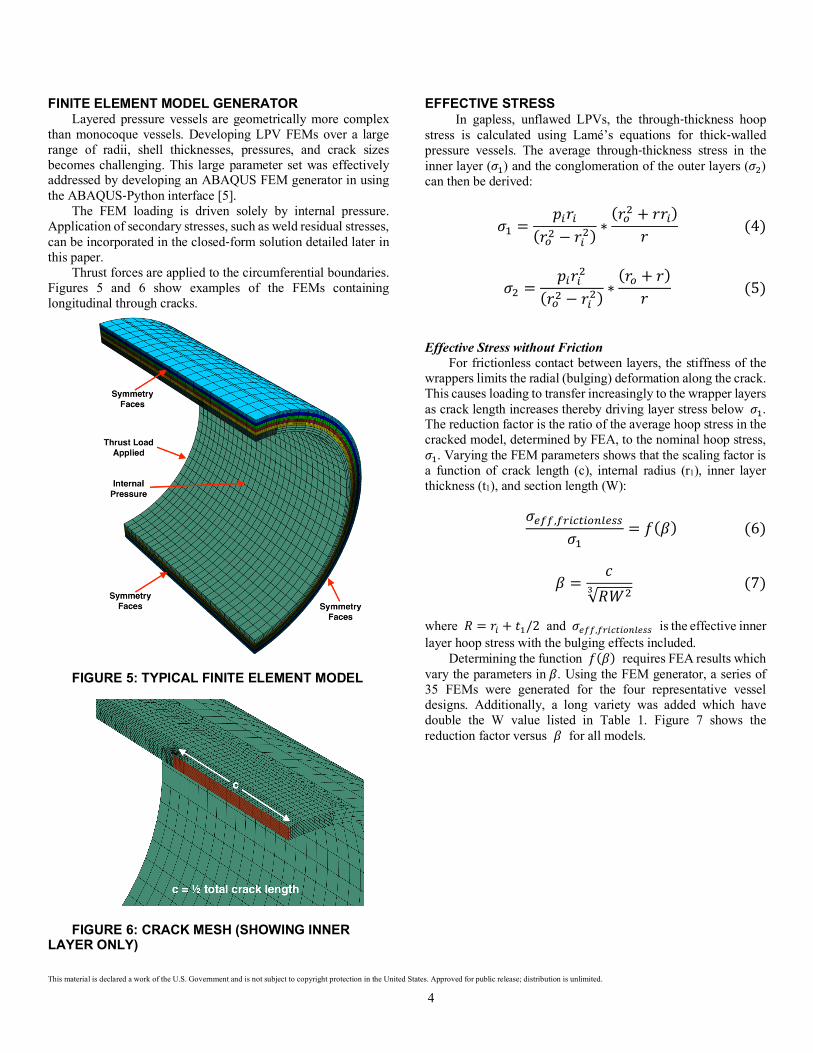
Thrust forces are applied to the circumferential boundaries. Figures 5 and 6 show examples of the FEMs containing longitudinal through cracks.
FIGURE 5: TYPICAL FINITE ELEMENT MODEL
FIGURE 6: CRACK MESH (SHOWING INNER
LAYER ONLY)
EFFECTIVE STRESS In gapless, unflawed LPVs, the through-thickness hoop
stress is calculated using Lamé’s equations for thick-walled pressure vessels. The average through-thickness stress in the inner layer (𝜎O) and the conglomeration of the outer layers (𝜎F) can then be derived:
𝜎O =𝑝Q𝑟Q
(𝑟SF − 𝑟QF)∗(𝑟SF + 𝑟𝑟Q)
𝑟 (4)
𝜎F =𝑝Q𝑟QF
(𝑟SF − 𝑟QF)∗(𝑟S + 𝑟)
𝑟 (5) Effective Stress without Friction
For frictionless contact between layers, the stiffness of the wrappers limits the radial (bulging) deformation along the crack. This causes loading to transfer increasingly to the wrapper layers as crack length increases thereby driving layer stress below 𝜎O. The reduction factor is the ratio of the average hoop stress in the cracked model, determined by FEA, to the nominal hoop stress, 𝜎O. Varying the FEM parameters shows that the scaling factor is a function of crack length (c), internal radius (r1), inner layer thickness (t1), and section length (W):
𝜎UVV,VXQYCQSZ[U\\
𝜎O= 𝑓(𝛽)(6)
𝛽 =
𝑐√𝑅𝑊Fa (7)
where 𝑅 = 𝑟Q + 𝑡O/2 and 𝜎UVV,VXQYCQSZ[U\\ is the effective inner layer hoop stress with the bulging effects included.
Determining the function 𝑓(𝛽) requires FEA results which vary the parameters in𝛽. Using the FEM generator, a series of 35 FEMs were generated for the four representative vessel designs. Additionally, a long variety was added which have double the W value listed in Table 1. Figure 7 shows the reduction factor versus 𝛽 for all models.

This material is declared a work of the U.S. Government and is not subject to copyright protection in the United States. Approved for public release; distribution is unlimited. 5
FIGURE 7: REDUCTION FACTOR VS. 𝜷
Fitting the data above yields the following stress scaling factor:
𝑓(𝛽) = 1.01 − 0.1341β − 1.0607𝛽F(8)
This scaling factor 𝑓(𝛽) is specific to materials with elastic moduli at or near that of steel - 29,500 ksi (203 GPa) and ν=0.3. Effective Stress with Friction
When friction is included, load transfer between the layers is dominated by the generated surface tractions which suppress crack opening displacements. Calculation of the effective stress in the inner layer with friction (𝜎UVV,eXQYCQSZ) requires wrapper layer stress (𝜎F) and thicknesses:
𝜎UVV,eXQYCQSZ =𝑡O𝜎O + 𝑡F𝜎F𝑡O + 𝑡F
(9) As will be seen, the magnitude of the normal (radial) stress
at the interface between the inner and first wrapper layer is also required for the closed-form KI expression.
𝜎ZSXf = g𝑝Q𝑟QF
𝑟SF − 𝑟QFh1 −
𝑟SF
𝑟Fig (10)
STRESS INTENSITY FACTORS
Rearranging Eq.(1) allows the correction factor to be calculated from KI output by the FEA as a function of crack length and effective stress:
𝛶 =𝐾#
𝜎UVV√𝜋𝑐(11)
Extensive FEAs performed over LPV geometries enabled the development of expressions for 𝛶. Once the key parameters were identified, a Buckingham Pi analysis was performed to determine dimensionless parameters and final KI expression.
Stress Intensity Factors without Friction
The sensitivity and Buckingham Pi analysis for the frictionless model yielded a unitless parameter that is a function of the geometry and crack length:
𝛼 =𝑐
<(𝑡O + 𝑡F) k𝑅 +𝑡F2l(12)
Figure 8 shows the relationship between 𝛼 and
𝛶VXQYCQSZ[U\\ .
FIGURE 8: FRICTIONLESS CONTACT
CORRECTION FACTOR VS. 𝜶
The data is then fitted by: 𝛶VXQYCQSZ[U\\ = 1.035 + 0.304𝛼 − 0.0363𝛼F(13)
where 0 ≤ 𝛼 ≤ 3.0 , 𝑐/𝑊 ≤ 0.25 , 𝜈 = 0.3 , and 𝐸 =29,500𝑘𝑠𝑖 (203𝐺𝑃𝑎) . The curve fit is biased towards the higher correction factors to ensure conservative estimates of KI. Stress Intensity Factors with Friction
The sensitivity and Buckingham Pi analysis for the model with friction yielded a unitless parameter 𝛱O that is a function of the geometry, crack length, friction factor, and normal stress:
𝛱O = w𝑡F
𝑡O(𝑡O + 𝑡F)𝑐F
𝑐XUV∗𝜇𝜎ZSXf𝜎XUV
(14)

This material is declared a work of the U.S. Government and is not subject to copyright protection in the United States. Approved for public release; distribution is unlimited. 6
where 𝑐XUV = 1𝑖𝑛(25.4𝑚𝑚) and 𝜎XUV = 1𝑘𝑠𝑖(6.89𝑀𝑃𝑎).
FEA was used to generate KI values for four LPV designs, 3 friction factors, and six crack length at various internal pressures for a total of seventy-two solutions. Figure 9 shows 𝛱O versus 𝛶VXQYCQSZ for all models.
FIGURE 9: CORRECTION FACTOR VS. 𝜫𝟏
Equation 15 is a third-order polynomial curve fit of the data in Fig. (9).
𝛶VXQYCQSZ = 1.11 − 0.0688 ∗ ΠO + 2.74 ∗ 10~I ∗ ΠOF − (15) 4.28 ∗ 10~� ∗ ΠOI
where𝛱O ≤ 30, 𝜈 = 0.3, and 𝐸 = 29,500𝑘𝑠𝑖 (203𝐺𝑃𝑎). EVALUATION OF KI EXPRESSIONS
The closed-form KI expressions were checked by comparing their values to the finite element results using Eq.(16).
%𝑜𝑓𝐹𝐸𝑀𝑟𝑒𝑠𝑢𝑙𝑡 =𝐾#,;[S\U�-eSXf8S�U[
𝐾#,e�8(16)
In Tables 2-5, cells are filled green when the through-
thickness average KI is within ±10% of the FEM value, red when below 90% of the FEM value, and blue when above 110% of the value.
TABLE 2: N-32-S Closed-Form Model Divided by FEM Results
2c, in (mm) µ =0.0 µ =0.8 µ =0.6 µ =0.3 1 (25.4) 1.05 1.02 1.01 1.01 4 (102) 1.01 1.01 0.98 0.94 8 (203) 0.98 1.01 0.97 0.90 12 (305) 0.99 1.02 0.99 0.90 16 (406) 1.00 1.02 0.99 0.91 20 (508) 0.97 1.00 0.99 0.91
TABLE 3: V32 Closed-Form Model Divided by FEM Results
2c, in (mm) µ =0.0 µ =0.8 µ =0.6 µ =0.3 1 (25.4) 1.05 0.98 0.97 0.97 4 (102) 1.05 1.03 1.01 0.97 8 (203) 1.07 1.04 1.03 0.98 12 (305) 1.10 1.03 1.03 0.99 16 (406) 1.12 1.02 1.02 0.98 20 (508) 1.12 1.01 1.01 0.98
TABLE 4: V12 Closed-Form Model Divided by FEM Results
2c, in (mm) µ =0.0 µ =0.8 µ =0.6 µ =0.3 1 (25.4) 1.04 0.99 0.99 0.99 4 (102) 1.06 1.03 1.02 1.00 8 (203) 1.06 1.04 1.03 0.99 12 (305) 1.06 1.03 1.02 0.97 16 (406) 1.05 1.02 1.00 0.96 20 (508) 1.03 1.01 0.99 0.94
TABLE 5: V256 Closed-Form Model Divided by FEM Results
2c, in (mm) µ =0.0 µ =0.8 µ =0.6 µ =0.3 1 (25.4) 1.04 0.99 0.99 0.99 4 (102) 1.06 1.03 1.02 1.00 8 (203) 1.06 1.04 1.03 0.99 12 (305) 1.06 1.03 1.02 0.97 16 (406) 1.05 1.02 1.00 0.96 20 (508) 1.03 1.01 0.99 0.94
SUMMARY Finite element analyses demonstrate that existing,
longitudinal through-crack solutions for monocoque pressure vessels do not produce realistic stress-intensity factors (KI) for cracks in LPVs. Friction plays a dominant role in reducing the KI values for longer cracks.

This material is declared a work of the U.S. Government and is not subject to copyright protection in the United States. Approved for public release; distribution is unlimited. 7
A closed-form expression for stress intensity factors is presented for inner layer, longitudinal through cracks in steel LPVs. This was developed using a combination of dimensional analysis and finite element analysis. Solutions are given for both friction and frictionless conditions. Seventy-two FEAs representing a combinations of vessel designs, crack lengths and friction factors were compared to the closed-form expression. The results show the closed-form model is slightly conservative on average (101%) without producing excessively conservative (max 112%) or un-conservative (min 90%) estimates of KI. ACKNOWLEDGEMENTS
Dr. Robert Dodds of the University of Tennessee and Brian Stoltz of NASA Marshall Space Flight Center are thanked for providing helpful advice and feedback. REFERENCES [1] Prosser, W. H., “Evaluation of Agency Non-code Layered
Pressure Vessels (LPVs),” NASA/TM-2014-218505, 2014 [2] Wang, Y., Soler, A. I., Chen, G.-L., “The “Self-Rescue”
Capacity of Wrapped Vessels-A Theoretical and Experimental Analysis,” J. of Pressure Vessel Technology, Vol. 112, pp 410-416
[3] Seipp, T. G., Stonehouse, M., Ormsbee, C, “Considerations in Using FEA for Layered Pressure Vessel Construction,” Proceeding of the ASMS Pressure Vessel and Piping Division/K-PVP Conference, PVP2010-26127, Bellevue, Washington, 2010
[4] Newman, J.C., Jr., “Fracture Analysis of Surface and Through Cracks in Cylindrical Pressure Vessels,” NASA TN D-8325, 1976
[5] ABAQUS User’s Manual, Version 6.14, 2014