Embed Size (px)
Citation preview
Page 1 of 11
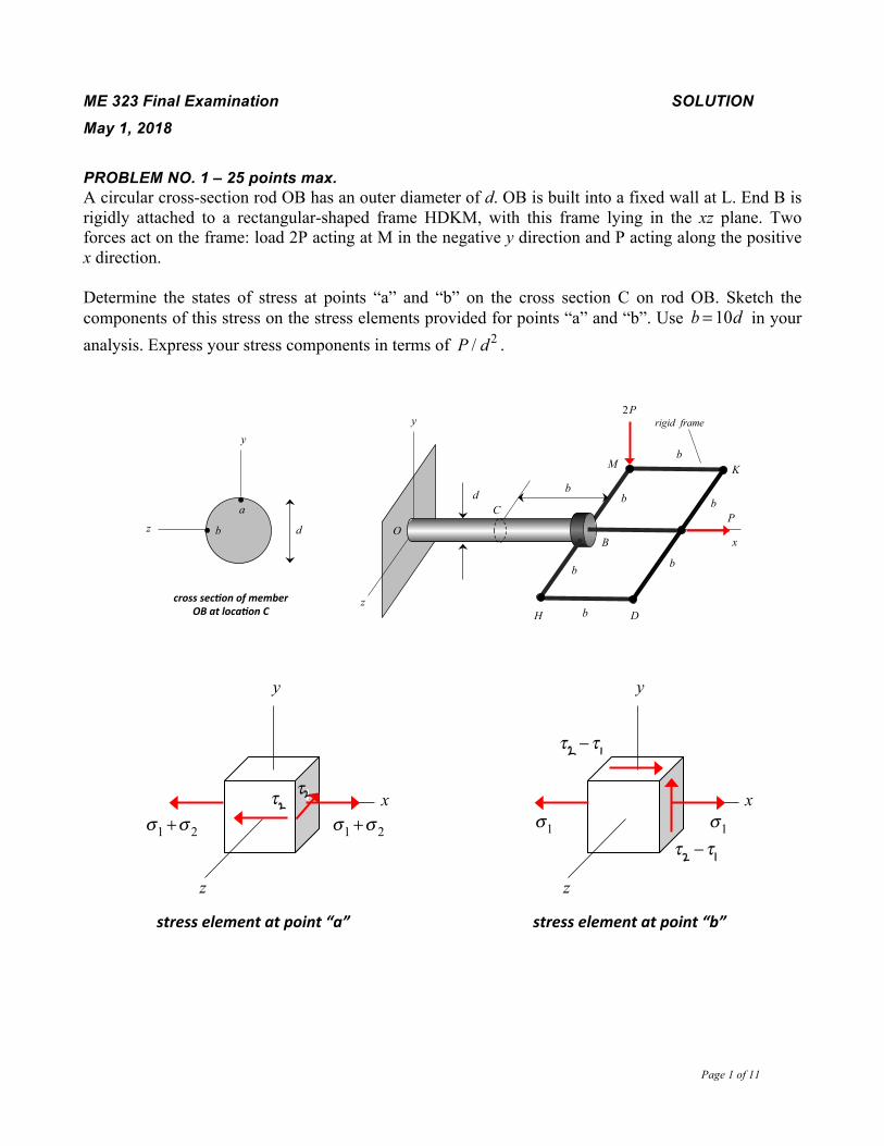
ME 323 Final Examination SOLUTION May 1, 2018 PROBLEM NO. 1 – 25 points max. A circular cross-section rod OB has an outer diameter of d. OB is built into a fixed wall at L. End B is rigidly attached to a rectangular-shaped frame HDKM, with this frame lying in the xz plane. Two forces act on the frame: load 2P acting at M in the negative y direction and P acting along the positive x direction. Determine the states of stress at points “a” and “b” on the cross section C on rod OB. Sketch the components of this stress on the stress elements provided for points “a” and “b”. Use b = 10d in your analysis. Express your stress components in terms of P / d2 .
b
b
b
b
x
y
z
b
b
b
P
2P
d
B
C
D H
K
a
b d O
M
crosssec'onofmemberOBatloca'onC
rigid frame
z
y
x
z
y
x
z
y
stresselementatpoint“a” stresselementatpoint“b” x
z
y
x
z
y
stresselementatpoint“a” stresselementatpoint“b”
σ1 +σ 2 σ1 τ1
σ1 +σ 2 σ1
τ1
τ2 −τ1
τ2 −τ1

Page 2 of 11
FBDs for equilibrium
Stress components from the four resultants
x
P
2P
B
C
D H
K M
Fy
Fx Tx
Mz
C
O
z
y
Mz
Tx Fx
Fy
a
b σ 2
y
x
a
b
τ1
y
x
a
b
Fx = P
Fy = 2P
Tx = 2Pb
Mz = 2Pb
σ1 =
FxA
= 4π
P
d2
σ 2 =Mzd2I
= 64bπd
Pd2
= 640π
Pd2
0
τ1 =
4Fy
3A= 32
3πPd2 0
τ2 =Txd2IP
= 32bπd
P
d2
= 320π
P
d2
point“a” point“b”
a
b σ1
y
x σ1
y
z τ2 τ2
stressdistribu0onresultant
A = π d2
4
I = π d4
64
IP = π d4
32
σ1 =
FxA
= 4π
P
d2
τ2 =Txd2IP
= 32bπd
P
d2
= 320π
P
d2

Page 3 of 11
ME 323 Final Examination SOLUTION May 1, 2018 PROBLEM NO. 2 – 25 points max. A point on the ski experiences a state of plane stress, when the components 𝜎!, 𝜎!, and 𝜏!" shown on the figure below.
a) Construct the Mohr’s circle of the state of stress. Indicate the following in the Mohr’s circle: the principal stresses and the maximum in-plane shear stress.
b) Show the principal stresses on a sketch of a properly oriented stress element. c) Determine the shear stresses and normal stresses in the plane of the maximum shear stress and
show these components of stress on a sketch of a properly oriented stress element. d) Determine the absolute maximum shear component of stress.

Page 4 of 11
ME 323 Final Examination SOLUTION May 1, 2018 PROBLEM NO. 3 – 25 points max.
The screwdriver experiences a torque 𝑇 = 10 𝑘𝑁 ∙𝑚 and an axial load 𝑃 = 800 𝑘𝑁 during its operation. Consider a point A on the surface of the circular rod section (of diameter 𝑑 = 0.1 𝑚). Ignoring gravity, answer the following:
a) Determine whether the rod section of the screwdriver will fail if it is made of cast iron with an ultimate stress of 𝜎! = 100 𝑀𝑃𝑎. Use the maximum-normal-stress theory.
b) Determine whether the rod section of the screwdriver will fail if it is made of steel with a yield stress of 𝜎! = 140 𝑀𝑃𝑎 using the:
i. maximum-shear-stress theory ii. maximum-distortion-energy theory

Page 5 of 11

Page 6 of 11
ME 323 Final Examination SOLUTION May 1, 2018 PROBLEM NO. 4 - PART A – 8 points max.
A mechanism is made up on a rigid crank link BC, a connecting rod CD and piston D. CD has a circular cross section with an outer diameter of d and with a length of L. The connecting rod CD is connected to the crank link and the piston with pin joints at C and D. During the operation of the mechanism, under the action of a torque M acting on the crank, the piston is being pressed against a fixed stop, as shown in the figure, keeping the mechanism in equilibrium.
Determine the maximum value of the torque M that can be applied in order to avoid buckling of the connecting rod CD. Use the Euler theory of buckling for your analysis. SOLUTION Using FBD of link BC:
M B∑ = FCDcosθ( ) Lsinθ( )− M = 0 ⇒ FCD = M
Lcosθsinθ
Using Euler buckling equation:
FCD( )cr
=Mcr
Lcosθsinθ= π 2 EI
L2 = π 2E πd4 / 64( )
L2 ⇒ Mcr =π 3
64Ed4
Lcosθsinθ
M
d
L
B
C
Dθ
fixed stop
B
C θ
FCD
D
C
FCD
FCD
By
Bx
M

Page 7 of 11
ME 323 Final Examination SOLUTION
May 1, 2018 PROBLEM NO. 4 - PART B – 2 points max.
Consider the state of stress shown above in a ductile material. Let σ MSS and σ MDE be the values of the normal stress σ above that correspond to failure of the material using the maximum shear stress and maximum distortional energy theories, respectively. Circle the answer below the best describes the relative sizes of σ MSS and σ MDE . Provide a brief written explanation for your answer.
a) σ MSS <σ MDE
b) σ MSS =σ MDE
c) σ MSS >σ MDE SOLUTION
σ ave =σ2
R = σ2
Therefore:
σ P1 =σ ave + R =σσ P2 =σ ave − R = 0
From this, we see that the principal components of stress lie on the σ P1 axis. The failure boundary on the σ P1 axis corresponds to a location where MSS and MDE results coincide.
σx
y
τ
x
y
σ P1
σ P2
σY ,σY( )
−σY ,−σY( )
0,−σY( )
0,σY( )
σY ,0( )
−σY ,0( ) σ P1
σ P2
σY ,σY( )
−σY ,−σY( )
0,−σY( )
0,σY( )
σY ,0( )
−σY ,0( )

Page 8 of 11
ME 323 Final Examination SOLUTION
May 1, 2018 PROBLEM NO. 4 - PART C – 2 points max.
Consider the state of stress shown above in a ductile material. Let τ MSS and τ MDE be the values of the shear stress τ above that correspond to failure of the material using the maximum shear stress and maximum distortional energy theories, respectively. Circle the answer below the best describes the relative sizes of τ MSS and τ MDE . Provide a brief written explanation for your answer.
a) τ MSS < τ MDE
b) τ MSS = τ MDE
c) τ MSS > τ MDE SOLUTION
σ ave = 0R = τ
Therefore:
σ P1 =σ ave + R = τσ P2 =σ ave − R = −τ
From this, we see that the principal components of stress lie on a 45° line in the 4th quadrant. On this line, we know that MSS is a more conservative estimate, or τ MSS < τ MDE .
σx
y
τ
x
y
σ P1
σ P2
σY ,σY( )
−σY ,−σY( )
0,−σY( )
0,σY( )
σY ,0( )
−σY ,0( ) σ P1
σ P2
σY ,σY( )
−σY ,−σY( )
0,−σY( )
0,σY( )
σY ,0( )
−σY ,0( )

Page 9 of 11
ME 323 Final Examination SOLUTION May 1, 2018 PROBLEM NO. 4 - PART D – 4 points max.
A circular cross-sectioned rod has outer diameter of d, a length of L and is made up of a material with a Young’s modulus of E and thermal coefficient of expansion of α . The rod is attached to rigid walls at ends B and C. With the rod being initially unstressed, the rod is heated in such a way that the temperature of the material in the rod is uniformly raised by an amount of ΔT . After this increase in temperature:
a) What is the strain in the rod? Leave your answer in terms of, at most, L, E, d, ΔT and α . With the ends of the rod fixed, no elongation of the rod is allowed. Therefore, the axial strain in the rod is zero.
b) What is the stress in the rod? Leave your answer in terms of, at most, L, E, d, ΔT and α . Again, with there being no elongation in the rod:
e = 0 = FL
EA+αΔTL = σ L
E+αΔTL ⇒ σ = −αΔTE
B C
d
L

Page 10 of 11
ME 323 Final Examination SOLUTION May 1, 2018 PROBLEM NO. 4 - PART E – 5 points max.
A shaft is made up of three concentrically aligned elements (1), (2) and (3), with these elements having outer diameters of d, 2d and 3d, respectively. The material makeup of these elements have shear moduli of G1 = 3G , G2 = 2G and G3 = G . All three elements are attached to a rigid wall at end B and to a rigid connector at end C. A torque T acts on the rigid connector at C, as shown in the above figure. Determine the radial distance ρ on the cross section of this composite shaft where the shear stress is a maximum. Also, what is the value of this maximum shear stress? Express your answer in terms of, at most, L, d, T and G. SOLUTION The shear strain γ = ρ dφ / dx varies linearly with ρ throughout the cross section of the shaft. With
τ = Gγ , the shear stress is stepwise linear with ρ . In the three elements:
τ1 = G1ρdφdx
= 3Gρ dφdx
⇒ τ1( )max= 3G
d2
dφdx
= 32
Gddφdx
τ2 = G2ρdφdx
= 2Gρ dφdx
⇒ τ2( )max= 2Gd
dφdx
τ3 = G3ρdφdx
= Gρ dφdx
⇒ τ3( )max= G
3d2
dφdx
= 32
Gddφdx
T = T1 +T2 +T3 =G1IP1φ
L+
G2IP2φL
+G3IP3φ
L= 3Gπ d4
32+ 2Gπ 31d4
32+Gπ 80d4
32
⎡
⎣⎢⎢
⎤
⎦⎥⎥
φL
= 14532
Gπd4 dφdx
⇒ dφdx
= 32145
T
πGd4 ⇒
τ2( )max
= 2Gddφdx
= 2Gd32
145T
πGd4⎛⎝⎜
⎞⎠⎟= 64
145T
πd3
(1)3( )
B
dT
ρ2d3d
C
2( )L
3( ) 2( ) (1)
ρ
G
2G3G
τ 3( )max
τ2( )maxτ1( )max
(MAXIMUM)

Page 11 of 11
ME 323 Final Examination SOLUTION May 1, 2018 PROBLEM NO. 4 - PART F – 4 points max.
A square cross-sectioned, cantilevered beam has a length of L, a depth of H and is made up of a material with a Young’s modulus of E. A bending couple M and an axial load P are applied to end C of the beam. The x-axis runs along the midline of the beam. For this loading, determine the y-location of the neutral plane of the beam. (Recall that the normal stress at the neutral plane is zero.) Leave your answer in terms of, at most, L, H, M, P and E. SOLUTION
σ = − My
I+ P
A
On the neutral surface σ = 0 :
σ ns = 0 = −
MynsI
+ PA
⇒ yns =IA
PM
= H 4 / 12H 2
PM
= 112
PH 2
M
x
y
B
PH
LM
C


![Finite Element Modeling for Stress Analysis[R.D.cook,1995]](https://img.dokumen.tips/doc/110x75/547ffaa2b4795978588b45a5/finite-element-modeling-for-stress-analysisrdcook1995.jpg)

