Embed Size (px)
Citation preview
International Research Journal of Engineering and Technology (IRJET) e-ISSN: 2395 -0056
Volume: 04 Issue: 06 | June -2017 www.irjet.net p-ISSN: 2395-0072
© 2017, IRJET | Impact Factor value: 5.181 | ISO 9001:2008 Certified Journal | Page 45
Stress analysis of splice joint in an aircraft fuselage with prediction of
fatigue life to crack initiation
Venkatesh Deshpande1, Pratik Phadnis2, S. P. Avadhani3
1Assistant Professor, Department of Mechanical Engineering, KLS Gogte institute of Technology, Belagavi,
Karnataka, India 2Assistant Professor, Department of Mechanical Engineering, KLS Gogte institute of Technology, Belagavi,
Karnataka, India 3Assistant Professor, Department of Mechanical Engineering, KLS Gogte institute of Technology, Belagavi,
Karnataka, India
---------------------------------------------------------------------***---------------------------------------------------------------------
Abstract - stress analysis of a splice joint in a transport
aircraft is studied in the current paper. Splice joint panel
consists of skin plates, doubler plat.e Alloy of Aluminium
2024-T351 is considered for all the structural elements of the
panel. We will be carrying out 2D Finite Element Analysis of
splice joint. At the rivet locations Distribution of fasteners
loads and local stress field. For a crack to initiate splice joint is
one of the critical location. At maximum stress location
prediction of fatigue life for crack initiation will be studied
Key Words: fuselage, splice joint, , crack propagation,
finite element analysis.
1.INTRODUCTION
A method of joining two members end to end is called Splice
joint, If the material length is not sufficient then we opt for
Splice joint. . As an alternate to Lap joint and Butt joint the
Splice joint can be used. For shear flows span wise the
splices are designed. In the majority of cases chord wise
loads are small and can be ignored. Due to cabin
pressurization the skin splices of longitudinal are designed
for Hoops tension loading but It is required to consider local
shear loads. Some times Skin and attachment both should be
considered for analysis. Fastener hole-out efficiency is to be
be maintained at 75 to 80 percent if a lower skin is designed
to lower margin of safety.
2. OBJECTIVE:
The dissertation works objective will be stress analysis of
splice joint in aircraft fuselage along prediction of fatigue life
to crack initiation. . For a study typical splice joint panel
consisting of skin plates, doubler plate is considered. For
structural analysis of a panel Aluminium alloy 2024-T351
material is considered. On a splice joint panel a two-
dimensional finite element-analysis will be carried out.
3. METHODOLOGY
In aerospace design, fatigue analysis is routinely used to
minimize the fatigue accidents, as every component added
important to aircraft. Therefore minimization of fatigue has
played a significant role in aircraft industry.
4. DESIGN METHODOLOGY
Linear Static Analysis:
CATIA V4 is used for the geometric modeling of the
structure for the linear static analysis of the splice joint
panel. Then abstraction of mid faces can be done. . For
preprocessor the model is impoted , where MSC Patran V7 is
used. Using MSC Patran a finite element model is created.
For a model all the element properties, boundary conditions
and loads are applied . For solving purpose MSC/.Nastran is
used. After solving the model, it is again imported to MSC
Patran for post processing. The results are obtained using
MSC Patran and are plotted
1st phase: Stress analysis
2nd phase: fatigue analysis
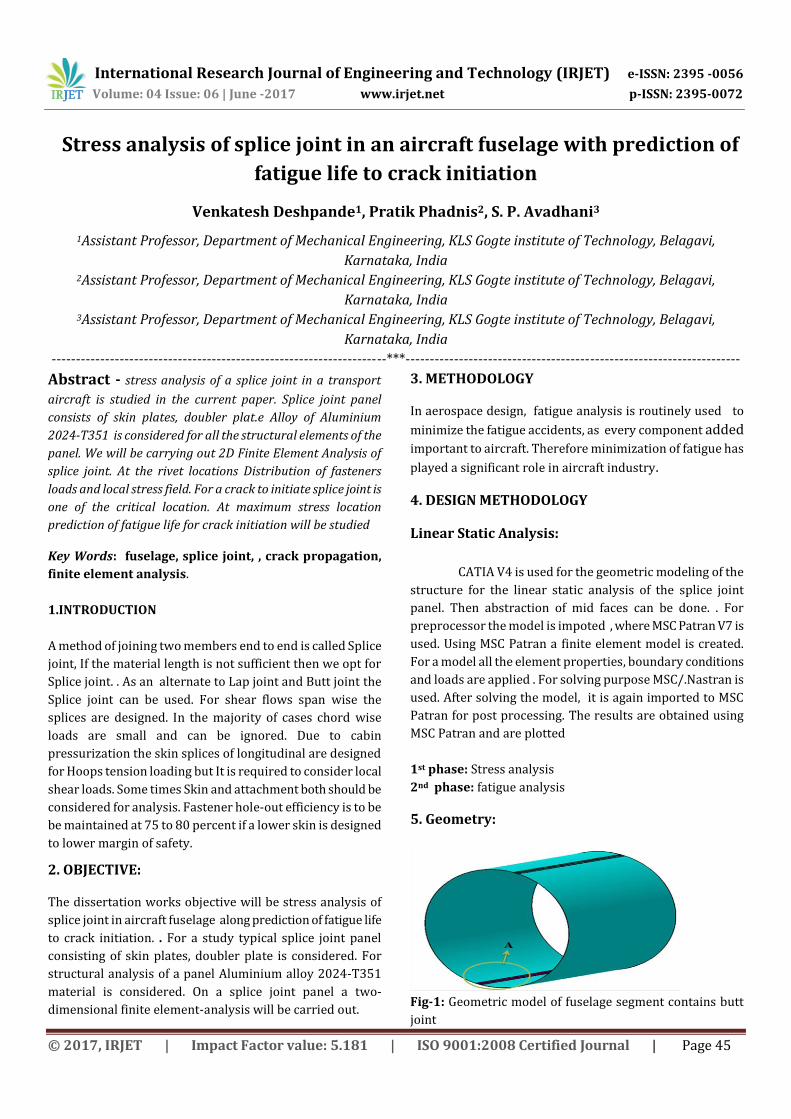
5. Geometry:
Fig-1: Geometric model of fuselage segment contains butt
joint

International Research Journal of Engineering and Technology (IRJET) e-ISSN: 2395 -0056
Volume: 04 Issue: 06 | June -2017 www.irjet.net p-ISSN: 2395-0072
© 2017, IRJET | Impact Factor value: 5.181 | ISO 9001:2008 Certified Journal | Page 46
Fig-2: Close-up view of geometric model for section A
contains butt joint
Fig-3: Geometric model of splice joint flat panel.
6. Meshing
Fig-4: Meshed group of fuselage segment consisting of
skin part
Fig-5: Global FE model of splice joint panel with loads and
Boundary Conditions
7. RESULTS AND DISCUSSIONS:
Fig-6: At thickness Z2 the static stress for von mises
stress contour at doubler side.
Fig-7: Free body loads taken by rivets
Table 1: Displacement and Von Mises stresses for
different pressure values
The stress contour and displacement contour as
Pressure
in PSI
Pressure
in
kg/mm2
Maximum Von mises
stresses in kg/mm2
at position
Displace
ment in
mm Z1 Z2
6 0.00422 10.8 18.1 3.02
6.5 0.00457 11.7 19.5 3.27
7 0.00493 12.7 21.1 3.53
7.5 0.00528 13.6 22.6 3.78
8 0.00563 14.5 24.1 4.03
8.5 0.00598 15.4 25.6 4.28
9 0.00633 16.3 27.1 4.53

International Research Journal of Engineering and Technology (IRJET) e-ISSN: 2395 -0056
Volume: 04 Issue: 06 | June -2017 www.irjet.net p-ISSN: 2395-0072
© 2017, IRJET | Impact Factor value: 5.181 | ISO 9001:2008 Certified Journal | Page 47
shown in above figures. It shows the static stresses
distribution of von mises stress tensor and the static
displacement variation.
The both skin part and doubler part of fuselage
segment under goes tensile stresses under pressure
loading and it’s deforming elastically.
From result contour, the stress at rivet hole in the
skin part is more and it under the condition of
elastic straining.
The maximum von-Mises stress for load case of 9PSI
at position Z2 is 27.1 kg/mm2
The Maximum Von-mises stresses at node id 47731
are observed from different pressure cycles.
8. REFERENCES
1. G. S. Campbell and R. Lahey “A survey of serious aircraft
accidents involving fatigue fracture” National Research
Council of Canada, Int J Fatigue Vol 6 No 1 January 1984,
ISBN 0142-1123/84/010025-06 © 1984 Butterworth &
Co Ltd.
2. J. Schijve “Fatigue of aircraft materials and structures”
Faculty of Aerospace Engineering, Delft University of
Technology, the Netherlands, Fatigue1994 volume 16
number1, ISBN 0142-1123/94/01/0021-12 © 1994
Butterworth-Heinemann Ltd.
3. R.J.H. Wanhill, M.F.J. Koolloos “Fatigue and corrosion in
aircraft pressure cabin lap splices” National Aerospace
Laboratory NL-1009 BM Amsterdam, the Netherlands,
International Journal of Fatigue 23 (2001) S337–S347,
© 2001 Elsevier Science Ltd.
4. M.R. Urban “Analysis of the fatigue life of riveted sheet
metal helicopter airframe joints” Structures Research
Department, Sikorsky Aircraft Corporation, USA,
International Journal of Fatigue 25 (2003) 1013–1026,
© 2003 Elsevier Ltd.
5. A.M. Brown, P.V. Straznicky “Simulating fretting contact
in single lap splices” Department of Mechanical and
Aerospace Engineering, Carleton University, Canada,
International Journal of Fatigue 31 (2009) 375–384,
2008, © Elsevier Ltd.