Embed Size (px)
Citation preview
STRENGTHENING OF CONCRETE AND MASONRY STRUCTURES WITH FIBER REINFORCED POLYMERS (FRP)
M Ehsani*, University of Arizona, USA
30th Conference on OUR WORLD IN CONCRETE & STRUCTURES: 23 - 24 August 2005,
Singapore
Article Online Id: 100030008
The online version of this article can be found at:
http://cipremier.com/100030008
This article is brought to you with the support of
Singapore Concrete Institute
www.scinst.org.sg
All Rights reserved for CI‐Premier PTE LTD
You are not Allowed to re‐distribute or re‐sale the article in any format without written approval of
CI‐Premier PTE LTD
Visit Our Website for more information
www.cipremier.com

30th Conference on OUR WORLD IN CONCRETE & STRUCTURES: 23 – 24 August 2005, Singapore
STRENGTHENING OF CONCRETE AND MASONRY STRUCTURES WITH FIBER REINFORCED POLYMERS (FRP)
M Ehsani*, University of Arizona, USA
Abstract
Since the late 1980s, the civil engineering community has become interested in the application of Fiber Reinforced Polymers (FRP) to the construction industry. These materials are comprised of very strong fibers and a resin matrix. The most popular application of FRPs has been in repair and rehabilitation of structures. In this technique, FRPs are bonded to the exterior surface of the structural element and will act as supplementary steel reinforcement for flexure, shear or confinement enhancement. High tensile strength, flexibility and lightweight of FRPs are among their salient advantages. This paper discusses some of the pioneering research conducted by the author and his associates and provides examples of field applications where FRPs have been successfully used.
Keywords: FRP, Strengthening, Repair, Seismic Upgrade, Pipe
1. Introduction Structural engineers are frequently faced with situations where the strength or ductility of existing elements must be increased. Strengthening is required for a variety of reasons including: a) original design errors that underestimated the actual loading on the members; b) construction errors that resulted in a weaker member; c) increased loading on the member due to change in use; and d) improvements in analytical tools and codes that demonstrate the inadequate strength of the member as it was originally designed and constructed. There are also cases where due to corrosion of reinforcement, the capacity of the member may have been compromised. While various codes do provide detailed guidelines for design of new structures, few provisions are available for strengthening existing structural members. As a result, the structural engineer and architect have more freedom in developing creative solutions to address the latter.
In the case of concrete structures, the traditional approach to correct the weakness of the element is by the addition of steel reinforcement. This usually involves drilling and anchoring dowels into the existing element, tying a new cage of steel reinforcement to the dowels and encasing the new steel in concrete. This procedure is often very intrusive and time consuming and it adds significant weight to the existing structure. Thus in some cases, the foundation of the structure has to be strengthened to safely carry the newly added mass.
A new technique that has gained popularity in recent years incorporates Fiber Reinforced Polymer (FRP) materials. These materials that have been used for many years in other industries such as shipbuilding and defense, offer unique solutions to the rehabilitation of the decaying civil infrastructure. The growing number of recent conferences attests to the interest of the profession on this subject (ACI-440 1996; Nanni and Dolan 1993; Taerwe 1995; El-Badry 1996; JCI 1997; Saadatmanesh and Ehsani 1996 and 1998). This paper introduces some of the material properties of FRPs and discusses a number of common applications as well as field applications.
2. Fiber Reinforced Polymers
Fiber Reinforced Polymers (FRPs) are made of long and continuous fibers (e.g. glass, carbon, etc.) bonded together with a resin matrix. The fibers provide the composites with their unique structural properties. The resin serves as the bonding agent to protect the fibers and to distribute the load among them. The most common type resins are polyesters, vinyl esters and epoxies. Anisotropy is a major advantage of FRPs; depending on the type of application, the fibers can be oriented in a multitude of directions to enhance the mechanical properties of the composite in the desired direction. A variety of fabric geometry and strength can be produced. The more common ones are unidirectional fabrics where all fibers are aligned in a single direction or biaxial fabrics where the fibers are placed in orthogonal directions. The fabric thickness is typically less than 2 mm and the addition of the resin matrix adds very little to the overall thickness. Depending on the required strength enhancement, two or more layers of fabric can be applied.
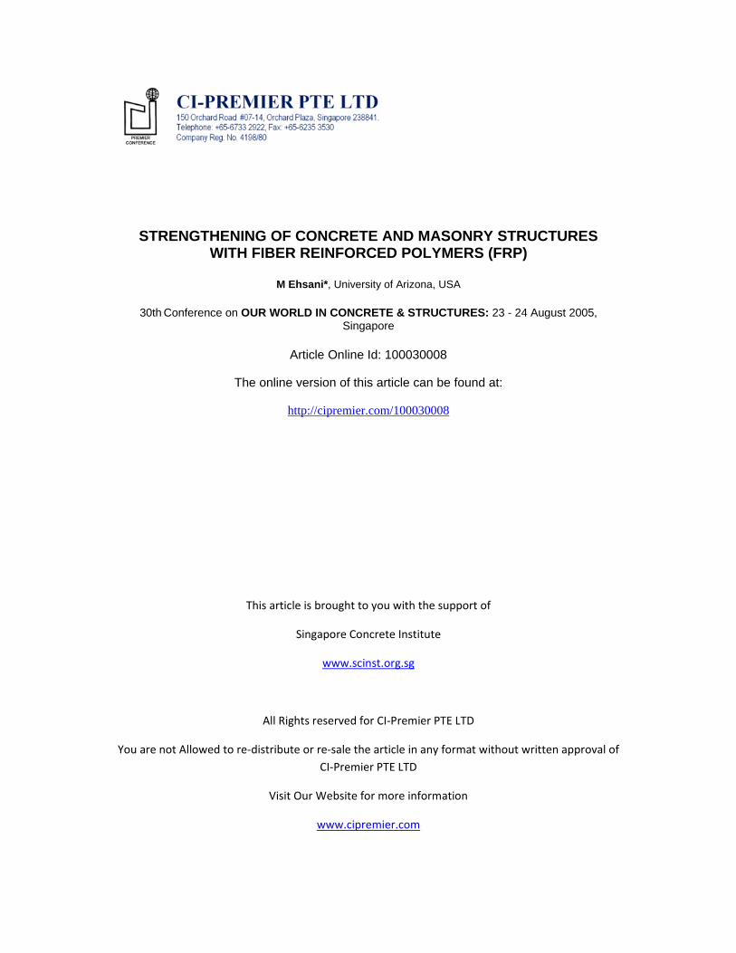
FRPs generally behave linearly elastic to failure. Carbon fibers, for example, have a tensile strength of over 2700 MPa and a modulus of elasticity of about 120 GPa. However, due to the progressive fracture of fibers, it is very difficult to achieve such high stresses in sections consisting of a large number of fibers. Furthermore, in most cases, the fibers account for 60% to 70% of the volume of the composite, with resins making up the balance. Due to the limited contribution of resin to the strength and stiffness, carbon FRPs have tensile strength in the range of 700 to 1000 MPa and modulus of elasticity of about 70 GPa. Figure 1 shows typical stress vs. strain diagrams for glass- and carbon-fiber-reinforced-polymers (GFRP and CFRP, respectively) and steel. It is important to note that although the behavior of composites is linear and elastic, their failure occurs at fairly large strains. Therefore, structural elements strengthened with these materials may fail at large deflections. 3. Construction Procedure Strengthening of structures with FRPs consists of a number of steps. First, the substrate surface that is to receive the FRP must be cleaned of any paint or other coating; this is usually achieved with sandblasting or water-blasting the surface. Next, a very thin layer of primer is applied to the cleaned surface; the primer is very low in viscosity and can be sprayed or brushed like paint. In the third stage, a layer of tack coat, about 1mm thick is applied; the tack coat is a high-viscosity epoxy with superior structural properties and is one of the most critical components of the system. The tack coat has a relatively long pot life and will remain tacky for two to three hours. The fourth stage involves bonding of the saturated fabric to the tack coat; this can be best achieved by running the fabric through an impregnator machine to ensure uniform saturation.
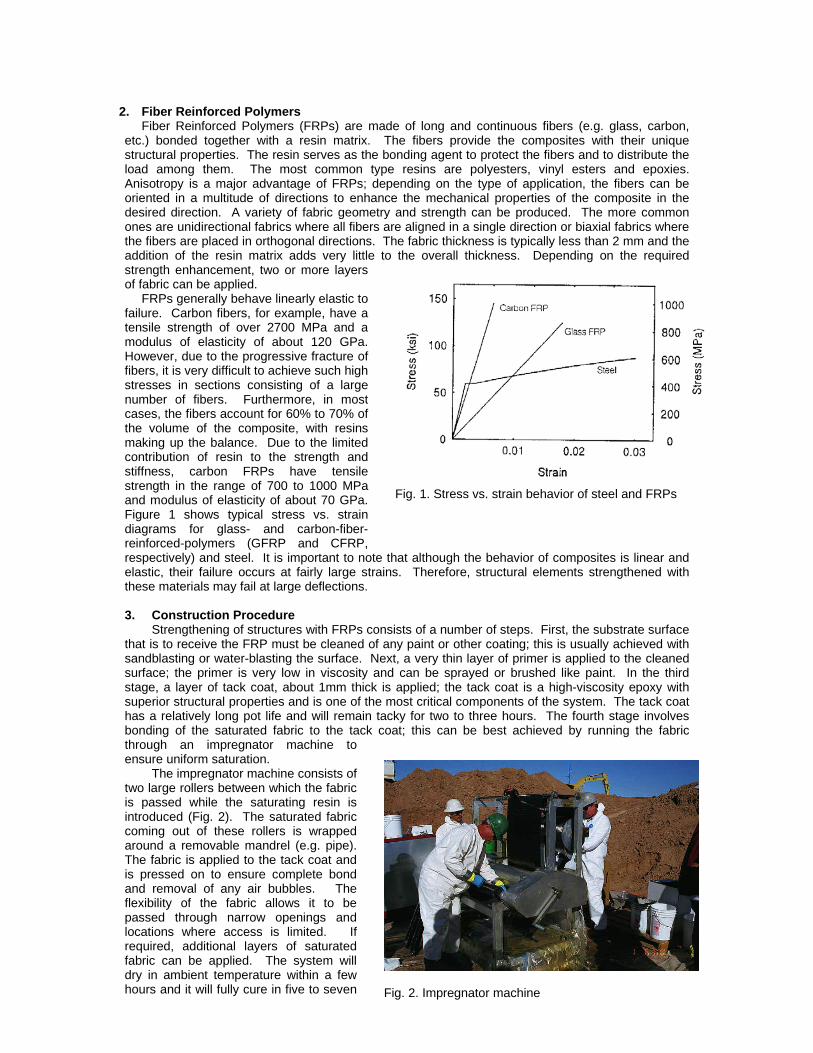
The impregnator machine consists of two large rollers between which the fabric is passed while the saturating resin is introduced (Fig. 2). The saturated fabric coming out of these rollers is wrapped around a removable mandrel (e.g. pipe). The fabric is applied to the tack coat and is pressed on to ensure complete bond and removal of any air bubbles. The flexibility of the fabric allows it to be passed through narrow openings and locations where access is limited. If required, additional layers of saturated fabric can be applied. The system will dry in ambient temperature within a few hours and it will fully cure in five to seven
Fig. 1. Stress vs. strain behavior of steel and FRPs
Fig. 2. Impregnator machine

days. If desired, the surface of the structure can be painted or covered with architectural coatings. In a variation of this approach, laminated FRP sheets are produced in a manufacturing plant by placing one or more layers of fabric or tows of fibers together with the resin matrix and often pressing and curing the laminate under heat. Sheets in thickness of roughly ½ to 3 mm are commonly produced with this approach; these sheets can be bonded directly to the tack coat in structures where the substrate surface is flat enough to warrant the use of such stiffer sheets. 4. Application of FRPs in Strengthening Structures FRPs can be employed in many applications as a substitute for steel that has been traditionally used for its high tensile strength. These include strengthening for flexure, shear, and confinement. In the following sections, each of these applications is introduced and the appropriate case studies are cited; all of these field applications have been performed by QuakeWrap, Inc. under the author’s supervision Due to space limitation, it would not be possible to present the research and development aspects of these applications in full detail; the reader is encouraged to refer to the numerous references cited throughout the paper for additional technical information.
5. Flexural Strengthening The initial developments of this concept took place in Germany where thick glass (GFRP) plates were used and in Switzerland where thin sheets of carbon (CFRP) were utilized (Meier 1987). These studies showed the validity of the strain compatibility method in the analysis of cross sections and suggested that inclined cracking may lead to premature failure by peeling-off of the strengthening sheet. Kaiser's study included the development of an analytical model for the composite plate anchoring which is in good agreement with test results (Kaiser 1989). In one of the earliest reported studies on this subject, five beams each having a cross-section of 90 x 153 mm and a length of 1.68 m were constructed. The beams were reinforced with a single 9-mm mild steel bar (Saadatmanesh and Ehsani 1990). Using a different epoxy for each beam, the beams were strengthened by bonding a 6x75 mm GFRP plate to the tension face. It was concluded that the success of this technique is greatly dependent on the use of a suitable epoxy and that the epoxy should have sufficient stiffness, strength and also toughness such as rubber toughened epoxies. After the completion of small-scale tests, another series of tests were carried out on five rectangular beams and one T-beam (Saadatmanesh and Ehsani 1991). Significant increase in the flexural strength of the beams was observed. In some of the lightly reinforced beams, this increase was as much as four fold. An analytical model was developed to predict the behavior of the retrofitted beam. As seen in Fig. 3, there is excellent correlation between the measured and predicted responses (An et al. 1991). This beam was initially cambered prior to the bonding of the plate; therefore, a negative deflection is recorded when there is no load applied to the beam. Similar results have been reported by others (Ritchie et al. 1991; Triantafillou, et al. 1992). Assuming that the debonding of the tack coat can be eliminated, several modes of failures exist; a general discussion of these failure modes is presented elsewhere (Ehsani and Saadatmanesh 1997). A number of buildings have been strengthened in the U.S. using this technique including the LSI Logic Corporation plant in Santa Clara, and a five-story high residential building in Westwood, California where the concrete slabs were strengthened. Similarly, concrete tilt-up wall panels that lack sufficient reinforcement can benefit from this approach. The Mitsubishi Corporation building in Compton, California and the Courtaulds Aerospace building in Glendale, California are examples of buildings that have been strengthened with this technique. A major application for flexural strengthening is in unreinforced masonry (URM) walls. There is a vast inventory of such structures worldwide. While the brick elements themselves have fairly good
Fig. 3. Load vs. deflection response of beam retrofitted with GFRP

compressive strength, the flexural capacity of these structures is controlled by the tensile strength of the mortar, which is often negligible. Numerous failures or collapses of URM structures have been recorded in previous earthquakes. In a system patented by the writer (Ehsani and Saadatmanesh 1997), composite fabrics can be applied to the surfaces of URM similar to wallpaper. The high tensile capacity of the FRP in conjunction with the compressive strength of masonry elements can resist substantial flexural stresses.
The behavior of such elements has been studied for some time at the University of Arizona (Ehsani and Saadatmanesh 1996; Ehsani, et al. 1997 and 1999; Velazquez-Dimas, et al. 2000; Velazquez-Dimas and Ehsani 2000). Single and double wythe walls have been constructed with reduced-scale solid bricks 49x38x102 mm in dimension. The wall heights varied from 710 mm to 2.74 m. The walls were retrofitted with various amounts of GFRP and were subjected to reversed cyclic loading using an airbag in the test frame shown in Fig. 4. The results shown in Fig. 5 are typical for a wall with different amounts of GFRP bonded to its two faces. On the south face, where the reinforcement level is lower, the wall carries a load five times greater than its weight; on the north face, where there is more reinforcement, the load resisted is more than twenty times the wall weight. The specimen also resisted more than fifteen loading cycles at displacements reaching 5% of the wall height. Clearly, this technique can enhance the flexural and deformation capacity of URM walls and can be beneficial in improving seismic performance of URM structures. Among the buildings that have been retrofitted with this technique is the United Airlines Building in Oakland International Airport, where the owner was concerned with the amount of dust that would be generated during a conventional retrofit.
Another recently completed project is the VA Medical Center in Tucson. The plans called for removal of the storage room that was attached to the boiler room. This removal caused concern about the stability of the wall. The strengthening of the wall with conventional approaches such as steel frames was ruled out because of the limited space available inside the room. A layer of a biaxial glass fabric was used to strengthen both inside and outside faces of the wall for shear and flexure. The middle photo in Fig. 6 shows the crew installing the fabric on the outer face of the wall; the photo on the right shows the finished and painted wall; note that the absence of the storage room.
Fig. 5. Load vs. deflection of URM wall retrofitted with GFRP
Fig. 4. Test setup for URM walls

Fig. 7. Flexural strengthening of concrete beams in a parking garage with GFRP
Fig. 6. Strengthening of the URM wall in VA Medical Center in Tucson, Arizona with GFRP Flexural strengthening of beams and slabs can also be easily achieved with FRPs. Figure 7 shows the beams in a parking garage in Arizona. Due to leaking from the roof, the inverted T-beams that support the prestressed double T-beams were damaged by corrosion. The original design that required addition of new steel beams and columns was very costly. The municipality decided to reopen the project to a design-build approach. The FRP alternative won that bid. The beams were wrapped in one layer of a biaxial glass fabric that weighed approximately 812 grams per square meter. The fibers that were parallel to the axis of the beam provided flexural strength while the fibers that were aligned in the vertical direction supplemented the shear strength of the beam. The project was completed in a very short period that resulted in cost savings to the city.
In another project completed in late 2004, a new Cath Lab was to be installed on the second floor of St. Joseph Hospital in Phoenix. This equipment weighed more than 2 tons and the existing slab could not support such a weight. Due to difficulty of access, strengthening from below was ruled out. A cantilever system was designed that would allow the slab to be strengthened from the top. Carbon laminates with a cross sectional dimension of 1.27 mm X 76 mm were bonded to the top surface of the slab (Fig. 8); these were later covered with a topping materials. Thus, the laminates were invisible at the completion of the project. The strengthening was done in one afternoon and caused minimal disruption. The lack of odor in the resin system was a major consideration for this project. Two other similar projects have been completed using QuakeWrap™ products since then, including a hospital in Anchorage, Alaska.
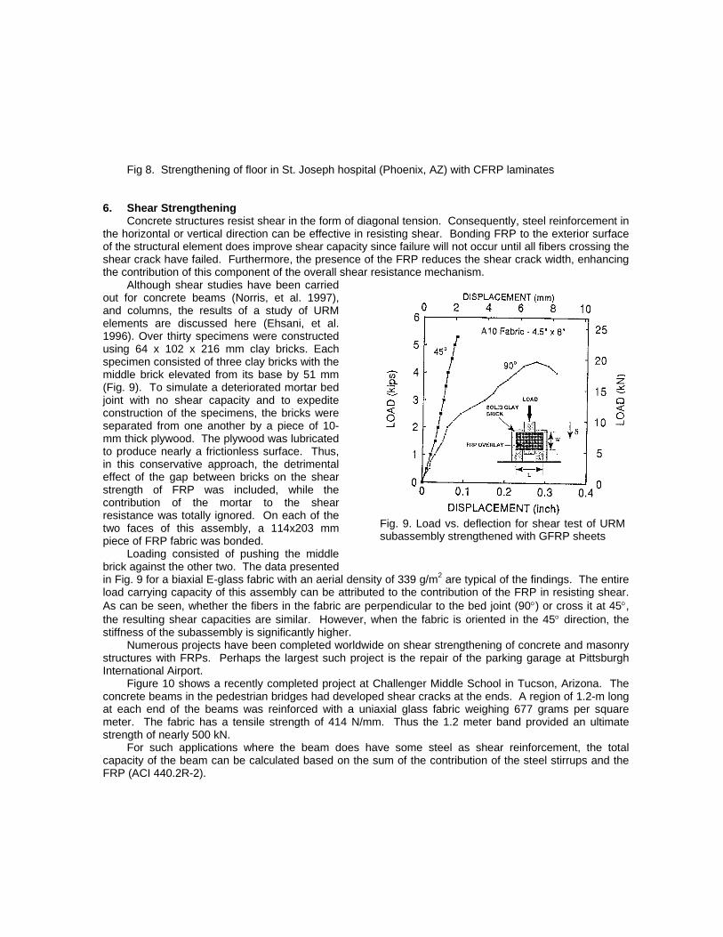
Fig. 9. Load vs. deflection for shear test of URMsubassembly strengthened with GFRP sheets
Fig 8. Strengthening of floor in St. Joseph hospital (Phoenix, AZ) with CFRP laminates 6. Shear Strengthening Concrete structures resist shear in the form of diagonal tension. Consequently, steel reinforcement in the horizontal or vertical direction can be effective in resisting shear. Bonding FRP to the exterior surface of the structural element does improve shear capacity since failure will not occur until all fibers crossing the shear crack have failed. Furthermore, the presence of the FRP reduces the shear crack width, enhancing the contribution of this component of the overall shear resistance mechanism.
Although shear studies have been carried out for concrete beams (Norris, et al. 1997), and columns, the results of a study of URM elements are discussed here (Ehsani, et al. 1996). Over thirty specimens were constructed using 64 x 102 x 216 mm clay bricks. Each specimen consisted of three clay bricks with the middle brick elevated from its base by 51 mm (Fig. 9). To simulate a deteriorated mortar bed joint with no shear capacity and to expedite construction of the specimens, the bricks were separated from one another by a piece of 10-mm thick plywood. The plywood was lubricated to produce nearly a frictionless surface. Thus, in this conservative approach, the detrimental effect of the gap between bricks on the shear strength of FRP was included, while the contribution of the mortar to the shear resistance was totally ignored. On each of the two faces of this assembly, a 114x203 mm piece of FRP fabric was bonded.
Loading consisted of pushing the middle brick against the other two. The data presented in Fig. 9 for a biaxial E-glass fabric with an aerial density of 339 g/m2 are typical of the findings. The entire load carrying capacity of this assembly can be attributed to the contribution of the FRP in resisting shear. As can be seen, whether the fibers in the fabric are perpendicular to the bed joint (90) or cross it at 45, the resulting shear capacities are similar. However, when the fabric is oriented in the 45 direction, the stiffness of the subassembly is significantly higher.
Numerous projects have been completed worldwide on shear strengthening of concrete and masonry structures with FRPs. Perhaps the largest such project is the repair of the parking garage at Pittsburgh International Airport.
Figure 10 shows a recently completed project at Challenger Middle School in Tucson, Arizona. The concrete beams in the pedestrian bridges had developed shear cracks at the ends. A region of 1.2-m long at each end of the beams was reinforced with a uniaxial glass fabric weighing 677 grams per square meter. The fabric has a tensile strength of 414 N/mm. Thus the 1.2 meter band provided an ultimate strength of nearly 500 kN.
For such applications where the beam does have some steel as shear reinforcement, the total capacity of the beam can be calculated based on the sum of the contribution of the steel stirrups and the FRP (ACI 440.2R-2).
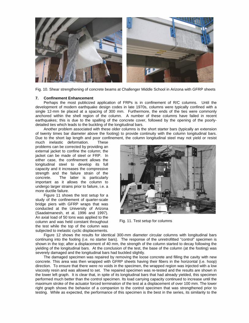
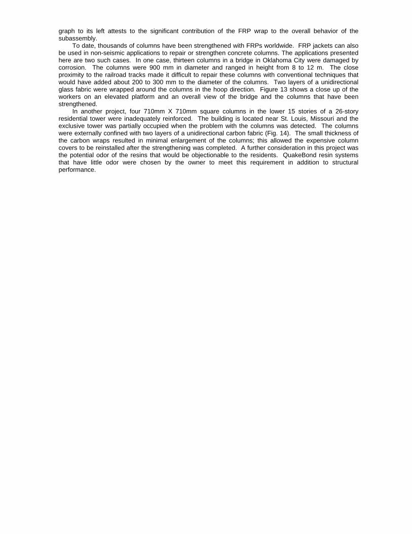
Fig. 11. Test setup for columns
Fig. 10. Shear strengthening of concrete beams at Challenger Middle School in Arizona with GFRP sheets 7. Confinement Enhancement Perhaps the most publicized application of FRPs is in confinement of R/C columns. Until the development of modern earthquake design codes in late 1970s, columns were typically confined with a single 12-mm tie placed at a spacing of 300 mm. Furthermore, the ends of the ties were commonly anchored within the shell region of the column. A number of these columns have failed in recent earthquakes; this is due to the spalling of the concrete cover, followed by the opening of the poorly-detailed ties which leads to the buckling of the longitudinal bars.
Another problem associated with these older columns is the short starter bars (typically an extension of twenty times bar diameter above the footing) to provide continuity with the column longitudinal bars. Due to the short lap length and poor confinement, the column longitudinal steel may not yield or resist much inelastic deformation. These problems can be corrected by providing an external jacket to confine the column; the jacket can be made of steel or FRP. In either case, the confinement allows the longitudinal steel to develop its full capacity and it increases the compressive strength and the failure strain of the concrete. The latter is particularly important as it allows the column to undergo larger strains prior to failure, i.e. a more ductile failure.
Figure 11 shows the test setup for a study of the confinement of quarter-scale bridge piers with GFRP wraps that was conducted at the University of Arizona (Saadatmanesh, et al. 1996 and 1997). An axial load of 50 tons was applied to the column and was held constant throughout the test while the top of the column was subjected to inelastic cyclic displacements. Figure 12 shows the results for identical 300-mm diameter circular columns with longitudinal bars continuing into the footing (i.e. no starter bars). The response of the unretrofitted "control" specimen is shown in the top; after a displacement of 40 mm, the strength of the column started to decay following the yielding of the longitudinal bars. At the conclusion of the test, the base of the column (at the footing) was severely damaged and the longitudinal bars had buckled slightly.
The damaged specimen was repaired by removing the loose concrete and filling the cavity with new concrete. This area was then wrapped with GFRP sheets having their fibers in the horizontal (i.e. hoop) direction. To ensure that there were no voids in the specimen, the wrapped region was injected with a low viscosity resin and was allowed to set. The repaired specimen was re-tested and the results are shown in the lower left graph. It is clear that, in spite of its longitudinal bars that had already yielded, this specimen performed much better than the control specimen. Its load carrying capacity continued to increase until the maximum stroke of the actuator forced termination of the test at a displacement of over 100 mm. The lower right graph shows the behavior of a companion to the control specimen that was strengthened prior to testing. While as expected, the performance of this specimen is the best in the series, its similarity to the
graph to its left attests to the significant contribution of the FRP wrap to the overall behavior of the subassembly. To date, thousands of columns have been strengthened with FRPs worldwide. FRP jackets can also be used in non-seismic applications to repair or strengthen concrete columns. The applications presented here are two such cases. In one case, thirteen columns in a bridge in Oklahoma City were damaged by corrosion. The columns were 900 mm in diameter and ranged in height from 8 to 12 m. The close proximity to the railroad tracks made it difficult to repair these columns with conventional techniques that would have added about 200 to 300 mm to the diameter of the columns. Two layers of a unidirectional glass fabric were wrapped around the columns in the hoop direction. Figure 13 shows a close up of the workers on an elevated platform and an overall view of the bridge and the columns that have been strengthened.
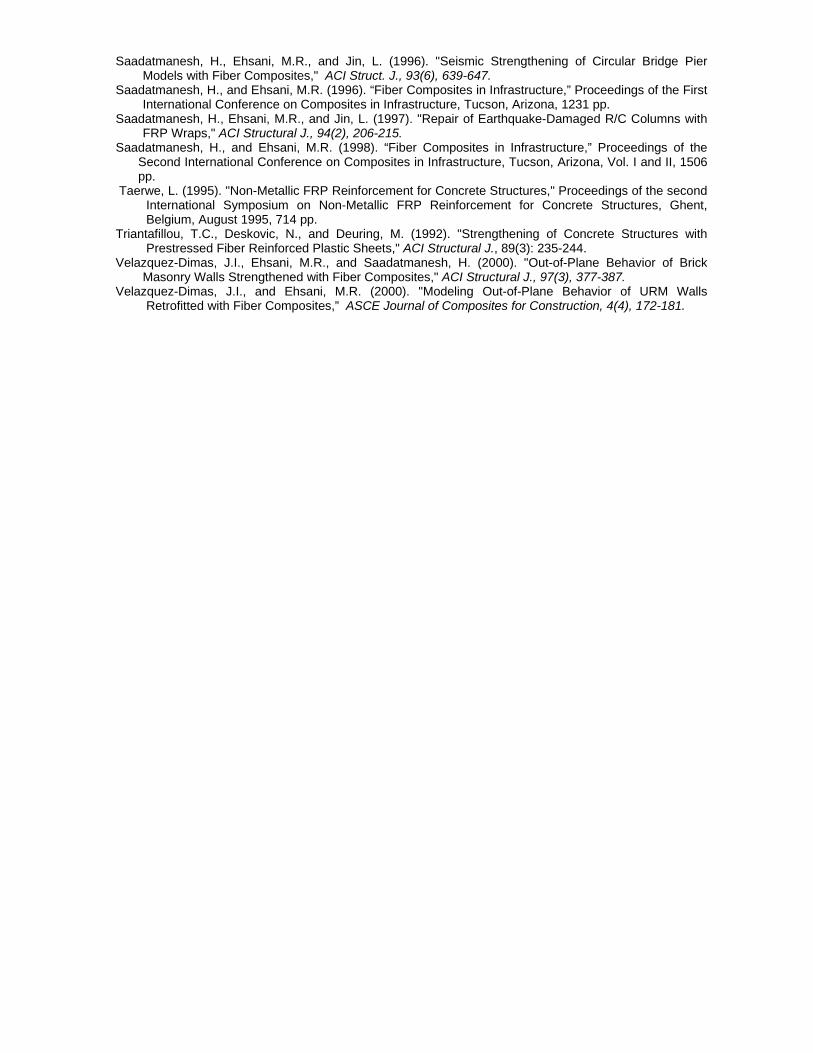
In another project, four 710mm X 710mm square columns in the lower 15 stories of a 26-story residential tower were inadequately reinforced. The building is located near St. Louis, Missouri and the exclusive tower was partially occupied when the problem with the columns was detected. The columns were externally confined with two layers of a unidirectional carbon fabric (Fig. 14). The small thickness of the carbon wraps resulted in minimal enlargement of the columns; this allowed the expensive column covers to be reinstalled after the strengthening was completed. A further consideration in this project was the potential odor of the resins that would be objectionable to the residents. QuakeBond resin systems that have little odor were chosen by the owner to meet this requirement in addition to structural performance.

Fig. 12 Hysteretic response of columns: (a) original, (b) repaired after damage, and (c) retrofitted
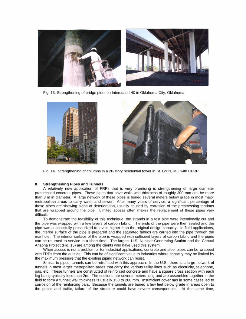
Fig. 13. Strengthening of bridge piers on Interstate I-40 in Oklahoma City, Oklahoma Fig. 14. Strengthening of columns in a 26-story residential tower in St. Louis, MO with CFRP 8. Strengthening Pipes and Tunnels A relatively new application of FRPs that is very promising is strengthening of large diameter prestressed concrete pipes. These pipes that have walls with thickness of roughly 300 mm can be more than 3 m in diameter. A large network of these pipes is buried several meters below grade in most major metropolitan areas to carry water and sewer. After many years of service, a significant percentage of these pipes are showing signs of deterioration, usually caused by corrosion of the prestressing tendons that are wrapped around the pipe. Limited access often makes the replacement of these pipes very difficult. To demonstrate the feasibility of this technique, the strands in a test pipe were intentionally cut and the pipe was wrapped with a few layers of carbon fabric. The ends of the pipe were then sealed and the pipe was successfully pressurized to levels higher than the original design capacity. In field applications, the interior surface of the pipe is prepared and the saturated fabrics are carried into the pipe through the manhole. The interior surface of the pipe is wrapped with sufficient layers of carbon fabric and the pipes can be returned to service in a short time. The largest U.S. Nuclear Generating Station and the Central Arizona Project (Fig. 15) are among the clients who have used this system. When access is not a problem or for industrial applications, concrete and steel pipes can be wrapped with FRPs from the outside. This can be of significant value to industries where capacity may be limited by the maximum pressure that the existing piping network can resist. Similar to pipes, tunnels can be retrofitted with this approach. In the U.S., there is a large network of tunnels in most larger metropolitan areas that carry the various utility lines such as electricity, telephone, gas, etc. These tunnels are constructed of reinforced concrete and have a square cross section with each leg being typically less than 2m. The sections are several meters long and are assembled together in the field to form a tunnel; wall thickness is usually 150 to 200 mm. Insufficient cover has in some cases led to corrosion of the reinforcing bars. Because the tunnels are buried a few feet below grade in areas open to the public and traffic, failure of the structure could have severe consequences. At the same time,

Fig. 16. Repair of the Arizona State Hospital utility tunnelwith CFRP
replacement of a few damaged sections of a tunnel is impractical, considering the disruption of utility services that would result. Therefore, FRPs can provide an economical repair alternative. Figure 13 shows a tunnel that was recently fixed in Phoenix, Arizona. As can be seen in the photo, space is very tight and access is only available through manholes. The flexibility of FRPs makes them an ideal choice that would allow passage beyond the pipes so closely spaced to the walls while permitting work in such confined area. 9. Quality Assurance
As with all construction projects, quality control is a major concern when FRPs are used. The workers require training for safe handling and application of the products. The materials must be stored in the recommended temperature range; this may require special attention when the job site temperatures are either too hot or too cold. Care must also be taken that the resin components have not expired prior to application. In many cases, for larger projects, random samples of the saturated fabric are prepared by the contractor in the field and submitted later to an independent laboratory to determine the mechanical characteristics of the field-installed products. Testing of composite materials requires special equipment that may not be available in most civil engineering materials testing laboratories. It is noted however that this industry is at its infancy at this point. Undoubtedly, as the industry matures and a larger number of field applications become available, standards will be developed and improved to ensure high quality FRP products and applications. 10. Economical Considerations In most cases, the cost of rehabilitation is not related to the construction costs alone. Other factors, such as the potential permanent loss of leasable space and the short-term costs associated with loss of productivity and revenue generation by the occupants are major issues to be considered. In many projects, for example, access is limited; yet in others, the owners may wish to continue using the facility or at least portions of it while the retrofit activity is ongoing. In nearly all these cases, FRPs provide advantages compared to conventional techniques.
In terms of pure cost, the systems of resins and fabrics currently cost about $40-$70 per square meter for GFRP and two to three times as much for CFRP products, depending on the thickness or strength of the fabric that is used. However, it is expected that these costs will decrease in the future as the volume increases. As far as the labor is concerned, a crew of 3-4 workers can install about 100-150 m2 of materials in an eight-hour shift. In all projects reported here, the FRP retrofit alternative cost less than the
Fig. 15. Repair of 2.7-m diameter pipe with CFRP

conventional technique. This was in addition to other inherent advantages that the technique might have offered. 11. Conclusions Beam test results indicate that retrofitting of flexural reinforced concrete members with composite fabrics is a very effective technique for increasing the flexural and shear strength of these elements. Similar to steel-reinforced concrete structures where the mode of failure is governed by the amount of the reinforcement present, in these applications the amount and the strength of the fabric controls the mode of failure. Assuming that the epoxy does not fail prematurely, when lighter fabrics are used, the maximum load is that causing tension failure of the fabric. When heavier fabrics are used, the members will fail by either compression crushing of concrete or a shear failure at the plane passing through the longitudinal steel bars. Confinement of columns, and strengthening of masonry walls and concrete pipes are other applications where FRP products can be efficiently used. The numerous projects cited in this paper and elsewhere in the literature attest to the economical viability of FRPs. There is little doubt that the use of FRPs will grow significantly in the coming years. 12. Acknowledgements
All projects cited in this study were designed and constructed using QuakeWrap™ products. More detailed information on these products is available online at www.QuakeWrap.com.
13. References
ACI Committee 440. (1996). "State-of-the-Art Report on Fiber Reinforced Plastic Reinforcement for Concrete Structures," ACI 440R-96, American Concrete Institute, Detroit, Michigan, 68 p.
ACI Committee 440. (2002). "Guide for the Design and Construction of Externally Bonded FRP Systems for Strengthening Concrete Structures," ACI 440.2R-02, American Concrete Institute, Detroit, Michigan, 45 p.
An, W., Saadatmanesh, H., and Ehsani, M.R. (1991). "R/C Beams Strengthened with FRP Plates: Analysis and Parametric Study," J. of Structural Engineering, ASCE, 117(11): 3434-3455.
Ehsani, M.R., Saadatmanesh, H. (1996). "Seismic Retrofitting of URM Walls with Fiber Composites," J. of The Masonry Society, 14(2), 63-72.
Ehsani, M.R., Saadatmanesh, H., and Al-Saidy, A. (1997). “Shear Behavior of URM Retrofitted with FRP Overlays,” J. of Composites for Construction, ASCE, 1(1), 17-25.
Ehsani, M.R., Saadatmanesh, H. (1997). "Fiber Composites: An Economical Alternative for Retrofitting Earthquake-Damaged Precast-Concrete Walls," Earthquake Spectra, 13(2), 225-241.
Ehsani, M.R., Saadatmanesh, H., and Velazquez-Dimas, J.I. (1999). "Behavior of Retrofitted URM Walls under Simulated Earthquake Loading," ASCE Journal of Composites for Construction, 3(3) 134-142
Ehsani, M.R., Saadatmanesh, H. (1997). "Method of Strengthening Masonry and Concrete Walls with Composite Strap and High Strength Random Fibers," U.S. Patent No. 5,640,825, United States Patents and Trademark Office, Washington, D.C.
El-Badry, M. (1996). "Advanced Composite Materials in Bridges and Structures – 2nd International Conference," Canadian Society of Civil Engineers, Montreal, August 1996, 1027 pp.
Japan Concrete Institute. (1997). "Non-Metallic FRP Reinforcement for Concrete Structures," Proceedings of the Third International Symposium on Non-Metallic FRP Reinforcement for Concrete Structures, Sapporo, Japan, October 1997, Vols. I and II, 1541 pp.
Kaiser, H. (1989). "Strengthening of Reinforced Concrete with Epoxy-Bonded Carbon-Fiber Plastics," Ph.D. Thesis submitted to ETH, Zurich, Switzerland, (in German).
Meier, U. (1987). "Bridge Repair with High Performance Composite Materials," Materials und Technik, 4: 125-128 (in German).
Nanni, A., and Dolan, C.W. (1993). "Fiber-Reinforced-Plastic Reinforcement for Concrete Structures," Proceedings, ACI SP-138, American Concrete Institute, Detroit, Michigan, 977 pp.
Norris, T.D., Saadatmanesh, H., and Ehsani, M.R. (1997). "Shear and Flexural Strengthening of R/C Beams with Carbon Fiber Sheets," J. of Str. Engrg., ASCE, 123(7): 903-911.
Ritchie, P.A., Thomas, D.A., Lu, Le-Wu, and Connelly, G.M. (1991). "External Reinforcement of Concrete Beams Using Fiber Reinforced Plastics," ACI Structural Journal, 88(4): 490-499.
Saadatmanesh, H. and Ehsani, M.R. (1990). "Fiber Composite Plates Can Strengthen Concrete Beams," Concrete International, 12(3): 65-71.
Saadatmanesh, H., and Ehsani, M.R. (1991). "R/C Beams Strengthened With GFRP Plates: Experimental Study," J. of Str. Engrg., ASCE, 117(10): 3417-3433.
Saadatmanesh, H., Ehsani, M.R. and Li, M.W. (1994). "Strength and Ductility of Concrete Columns Externally Reinforced with Fiber Composite Straps," ACI Structural J., 91(4), 434-447.
Saadatmanesh, H., Ehsani, M.R., and Jin, L. (1996). "Seismic Strengthening of Circular Bridge Pier Models with Fiber Composites," ACI Struct. J., 93(6), 639-647.
Saadatmanesh, H., and Ehsani, M.R. (1996). “Fiber Composites in Infrastructure,” Proceedings of the First International Conference on Composites in Infrastructure, Tucson, Arizona, 1231 pp.
Saadatmanesh, H., Ehsani, M.R., and Jin, L. (1997). "Repair of Earthquake-Damaged R/C Columns with FRP Wraps," ACI Structural J., 94(2), 206-215.
Saadatmanesh, H., and Ehsani, M.R. (1998). “Fiber Composites in Infrastructure,” Proceedings of the Second International Conference on Composites in Infrastructure, Tucson, Arizona, Vol. I and II, 1506 pp.
Taerwe, L. (1995). "Non-Metallic FRP Reinforcement for Concrete Structures," Proceedings of the second International Symposium on Non-Metallic FRP Reinforcement for Concrete Structures, Ghent, Belgium, August 1995, 714 pp.
Triantafillou, T.C., Deskovic, N., and Deuring, M. (1992). "Strengthening of Concrete Structures with Prestressed Fiber Reinforced Plastic Sheets," ACI Structural J., 89(3): 235-244.
Velazquez-Dimas, J.I., Ehsani, M.R., and Saadatmanesh, H. (2000). "Out-of-Plane Behavior of Brick Masonry Walls Strengthened with Fiber Composites," ACI Structural J., 97(3), 377-387.
Velazquez-Dimas, J.I., and Ehsani, M.R. (2000). "Modeling Out-of-Plane Behavior of URM Walls Retrofitted with Fiber Composites,” ASCE Journal of Composites for Construction, 4(4), 172-181.