Embed Size (px)
Citation preview

Linkoping Studies in Science and Technology.Licentiate Thesis No. 1590
Strength analysis and modeling ofhybrid composite-aluminum
aircraft structures
Zlatan Kapidzic
LIU–TEK–LIC–2013:24
Division of Solid MechanicsLinkoping University, SE–581 83, Linkoping, Sweden
Linkoping, May 2013

Cover:The picture illustrates the results from a finite element simulation of a hybridstructure, including local and global fastener joint failure.
Printed by:LiU-Tryck, Linkoping, Sweden, 2013ISBN 978-91-7519-628-2ISSN 0280-7971
Distributed by:Linkoping UniversityDepartment of Management and EngineeringSE–581 83, Linkoping, Sweden
c© 2013 Zlatan KapidzicThis document was prepared with LATEX, April 30, 2013
No part of this publication may be reproduced, stored in a retrieval system, or betransmitted, in any form or by any means, electronic, mechanical, photocopying,recording, or otherwise, without prior permission of the author.

Preface
The work presented in this Licentiate in Engineering thesis has been carried out atSaab AB and at the Division of Solid Mechanics, Linkoping University. The workhas been performed within the project FoT-Flygteknik: Optimalt utnyttjande avavancerade strukturmaterial i hybrida skrovkonstruktioner - HYBRIS, and wasfunded by Swedish Defense Material Administration (FMV) and Saab AB.
First, I would like to thank my supervisors, Hans Ansell (Saab AB) and ProfessorLarsgunnar Nilsson, for all their support and guidance during the course of thiswork. For valuable discussions and comments on my work I would like to thank allmy colleagues within HYBRIS project and in particular Anders Bredberg (SaabAB). Also, I would like to thank all my colleagues at Saab AB and LinkopingUniversity for their help, encouragement and interesting discussions.
I am also grateful to my family and all my friends for their support. Especially, Iwould like to thank my dear Karin and my son Adrian for their patience and dailyencouragement.
Linkoping, May 2013
Zlatan Kapidzic
iii


Abstract
The current trend in aircraft design is to increase the proportion of fiber compositesin the structures. Since many primary parts also are constructed using metals, thenumber of hybrid metal-composite structures is increasing. Such structures havetraditionally often been avoided as an option because of the lack of methodologyto handle the mismatch between the material properties. Composite and metalproperties differ with respect to: thermal expansion, failure mechanisms, plastic-ity, sensitivity to load type, fatigue accumulation and scatter, impact resistanceand residual strength, anisotropy, environmental sensitivity, density etc. Basedon these differences, the materials are subject to different design and certifica-tion requirements. The issues that arise in certification of hybrid structures are:thermally induced loads, multiplicity of failure modes, damage tolerance, bucklingand permanent deformations, material property scatter, significant load states etc.From the design point of view, it is a challenge to construct a weight optimal hy-brid structure with the right material in the right place. With a growing numberof hybrid structures, these problems need to be addressed.
The purpose of the current research is to assess the strength, durability and thermo-mechanical behavior of a hybrid composite-aluminum wing structure by testing andanalysis. The work performed in this thesis focuses on the analysis part of the re-search and is divided into two parts. In the first part, the theoretical frameworkand the background are outlined. Significant material properties, aircraft certi-fication aspects and the modeling framework are discussed. In the second part,two papers are appended. In the first paper, the interaction of composite and alu-minum, and their requirements profiles, is examined in conceptual studies of thewing structure. The influence of the hybrid structure constitution and requirementprofiles on the mass, strength, fatigue durability, stability and thermo-mechanicalbehavior is considered. Based on the conceptual studies, a hybrid concept to beused in the subsequent structural testing is chosen. The second paper focuses onthe virtual testing of the wing structure. In particular, the local behavior of hybridfastener joints is modeled in detail using the finite element method, and the resultis then incorporated into a global model using line elements. Damage accumulationand failure behavior of the composite material are given special attention. Com-putations of progressive fastener failure in the experimental setup are performed.The analysis results indicate the critical features of the hybrid wing structure fromstatic, fatigue, damage tolerance and thermo-mechanical points of view.
v


List of Papers
The following papers have been included in this thesis:
I. Z. Kapidzic, L. Nilsson, H. Ansell, (2013), Conceptual studies of a composite-aluminum hybrid wing box demonstrator, Submitted.
II. Z. Kapidzic, L. Nilsson, H. Ansell, (2013), Finite element modeling of me-chanically fastened composite-aluminum joints in aircraft structures, Submit-ted.
Note
The papers have been reformatted to fit the layout of the thesis.
Author’s contribution
I have borne primary responsibility for all work presented in the papers includedin this thesis.
vii

The work in this project has also resulted in the following paper which is notincluded in this thesis:
I. Z. Kapidzic, R. Gutkin, (2013), Detailed modeling of low velocity impact on ahybrid wing box structure, Submitted to 4:th CEAS Air & Space Conference,September 16-19, 2013.
viii

Contents
Preface iii
Abstract v
List of Papers vii
Contents ix
Part I – Theory and Background 1
1 Introduction 31.1 HYBRIS-project . . . . . . . . . . . . . . . . . . . . . . . . . . . . 5
2 Material characterization 92.1 Static strength and stiffness . . . . . . . . . . . . . . . . . . . . . . 102.2 Fatigue damage development . . . . . . . . . . . . . . . . . . . . . . 14
3 Certification of aircraft structures 193.1 Analysis . . . . . . . . . . . . . . . . . . . . . . . . . . . . . . . . . 193.2 Testing . . . . . . . . . . . . . . . . . . . . . . . . . . . . . . . . . . 22
4 Constitutive modeling 254.1 Elastic behavior . . . . . . . . . . . . . . . . . . . . . . . . . . . . . 254.2 Failure criteria . . . . . . . . . . . . . . . . . . . . . . . . . . . . . 28
4.2.1 Limit criteria . . . . . . . . . . . . . . . . . . . . . . . . . . 294.2.2 Polynomial criteria . . . . . . . . . . . . . . . . . . . . . . . 294.2.3 Physically based criteria . . . . . . . . . . . . . . . . . . . . 30
4.3 Damage progression . . . . . . . . . . . . . . . . . . . . . . . . . . . 33
5 Finite element modeling 375.1 Modeling of bolted joints . . . . . . . . . . . . . . . . . . . . . . . . 375.2 Structural modeling . . . . . . . . . . . . . . . . . . . . . . . . . . . 40
6 Outlook 45
7 Review of included papers 47
ix

Bibliography 49
Part II – Included papers 55Paper I: Conceptual studies of a composite-aluminum hybrid wing box
demonstrator . . . . . . . . . . . . . . . . . . . . . . . . . . . . . . 59Paper II: Finite element modeling of mechanically fastened composite-
aluminum joints in aircraft structures . . . . . . . . . . . . . . . . . 83
x

Part I
Theory and Background


Introduction1
Aluminum alloys have, for a long time, been the primary materials used in air-craft structural design. Compared to most other metals, aluminum alloys have ahigh strength-to-weight ratio, which is essential for the aircraft performance andload-carrying capability. Aluminum alloys are, however, susceptible to fatigue andthis poses a problem considering that aircraft structures usually are exposed to alarge number of cyclic load repetitions during their operational life. The progressin material sciences and experimental techniques during the last century, as wellas development of spectrum fatigue analysis, fracture mechanics and crack growthanalysis, have advanced the knowledge of fatigue in metals and today the phe-nomenon is reasonably well-understood. Based on this knowledge, the aircraftindustry has developed methods for securing the fatigue durability, the damagegrowth tolerance and the static and residual strength of aircraft metal structureswith the aim of certifying their airworthiness and ensuring their structural integrity.
CompositeMetal
Figure 1: Composite and metal materials in JAS39 Gripen.
During the last three decades, the use of advanced light weight-high strength fiberreinforced polymers (FRP) composite materials in modern aircraft structures hasrapidly increased [1]. For instance, about 20% of the JAS39 Gripen structure ismade of FRP composite material, see Fig. 1. Based on the inherent propertydifferences between the composites and metals [2], other certification and designmethods adapted to the composites, had to be developed. Special attention waspayed to the fact that composite laminates are sensitive to out-of-plane stresses,impact, environmental influence, and that they exhibit a multiplicity of failure
3

CHAPTER 1. INTRODUCTION
modes both in static and cyclic loading. The designs resulting from these methodswere typically composite laminate panels that were sized to experience low in-planestrains and no, or very small, out-of-plane and interlaminar stresses. These designprecautions are the reason why so few in-service composite fatigue failures havebeen reported and why the composites have gained a reputation of being fatigueinsensitive.
With an increasing proportion of composite, the number of interfaces between met-als and composites is growing. Structural parts that are made of both metal andcomposite materials and that include such interfaces are referred to as hybrid struc-tures. Such mixed solutions have traditionally often been avoided as an alternative,because of the lack of a proper methodology to handle the mismatch of the materialproperties. But with a growing number of hybrid structures, this problem needsto be addressed. Some examples of differences between the properties of compos-ite laminates and aluminum alloys are: thermal expansion coefficients, failure andfracture mechanisms, degree of plasticity, response to different types of loading,i.e. tensile versus compressive and out-of-plane, fatigue accumulation and scatter,impact resistance, impact residual strength, degree of anisotropy, environmentalsensitivity, density etc. Based on these differences, composite and aluminum ma-terials used in aircraft structures are subject to different design and airworthinessrequirements. The issues that therefore arise with hybrid structures are: thermallyinduced stresses and deformations, multiplicity of failure modes in joints, unantici-pated structural failure modes, allowance of buckling and permanent deformations,determination of testing factors to account for material property scatter, determi-nation of significant load states etc. From a design point of view it is a challenge toconstruct a weight optimal hybrid structure, where the right material is put intothe right place.
The recommended practice for certification of composite assemblies, known as theBuilding Block Approach (BBA) [3], [4], is to conduct analysis and testing at var-ious levels of structural complexity. Usually, a large number of small specimensare tested and analyzed initially before progressing to more complex and expensivestructural components, and finally ending with the test of the complete assembly.The knowledge gained at the previous levels is used as the base for designing thetesting on the next level. In this way, the risks in technology associated with com-plexity of composites may be uncovered and eliminated at an early stage. Whenit comes to hybrid structures this approach may not always be appropriate, sincethe hybrid effects might be absent on lower structural levels. By this way of rea-soning, the analyzes and tests should be performed on a higher level first, in orderto evaluate the hybrid nature of a structure and to discover the unanticipatedstructural behavior. Such testing can be very costly and a lot of understandingcan be gained by performing detailed numerical analyzes prior to the testing. Forthat purpose, structural modeling techniques that include damage accumulationand failure progression need to be developed. Some typical structural featuresthat create a modeling challenge and a need for research are: bolted and bondedjoints, holes, ply drop-off regions, delaminations and imperfections, impact dam-
4

1.1. HYBRIS-PROJECT
ages, buckling panels etc. At Saab AB in Linkoping and FOI in Stockholm, suchresearch is conducted in the industrial project HYBRIS and this thesis is entirelybased on the work performed within that project.
1.1 HYBRIS-project
The aim of the HYBRIS project is to assess the behavior of a hybrid wing-likebox, with skins made of carbon fiber reinforced polymer (CFRP) and the innerstructure made of aluminum, by testing and analysis. The material and geometryconfiguration of the object of study is based on the typical features of the real wingstructure of Gripen aircraft, see Figs. 2 and 3. The structure is built of C-shapedspars and ribs bolted in a central splice section.
Figure 2: Wing structure of the JAS39 Gripen aircraft.
Figure 3: HYBRIS wing box with dimensions 3300x630x150 [mm].
5

CHAPTER 1. INTRODUCTION
The wing structure is normally exposed to bending and twisting operational loadsand temperatures between -40◦C and 80◦C. To simulate this loading on the wingbox, static and spectrum fatigue testing in a four point bending/twisting set upwith an applied temperature is performed. Besides of its hybrid features, thewing box contains skin defects such as artificial delaminations, low velocity im-pact damages and different types of ply drop-off regions. Also, the dimensioningrequirements used for composites, currently used in the industry, are modified forthe purpose of challenging the conservative assumptions and allowables. At the endof the test program, the wing box will be filled with water and fired at with a smallcaliber bullet to test its battle damage resistance. The test results are expectedto indicate the critical features of the hybrid box from static, fatigue and dam-age tolerance point of view. Also, the influence of thermally induced loads on thestructural behavior should be revealed. Prior to the testing, the following analysisof the test object are performed: conceptual studies of different hybrid solutionsand requirements, dimensioning analysis, local and global analysis of composite-aluminum bolted joints, impact analysis and virtual test simulation of the entiretest object. This thesis work deals with parts of the analysis and modeling workrelated to the conceptual studies and modeling of bolted joints in the test object.
In the conceptual studies, two different cross-section designs of a hybrid wing boxstructure, without the splice section, are studied. The structure is designed giventhe thermal and mechanical loads and with respect to current requirements forstatic strength, fatigue and stability. The structural response, the local and globalfailure modes and the resulting weights of the two concepts are compared. Thenthe requirements concerning allowable strains, allowable buckling load and giventhermal loads are modified and another comparison is preformed. Finally, oneof the concepts is chosen for testing. The work concerning conceptual studies isappended in Paper 1.
In appended Paper 2, the wing box to be used in testing, Fig. 3, is modeled andanalyzed using the finite element method (FEM). Special attention is payed to theshear loaded bolted joints present in the structure. A methodology is developed inwhich the local joint behavior, including damage accumulation in composite andmetal plasticity, is assessed first. This behavior is then assigned to the structuralelements representing the bolts in the global model of the wing box. Simulationswith applied thermal and mechanical loads in the test setup are performed and theprogressive failure of bolted joints is studied.
Certification of aircraft structures is, even without effects of hybrid structures, avery complex matter with a lot of different aspects and challenges. More efforts inthe development of methodologies, modeling tools, testing strategies and furtherresearch of material and interface behavior are required to obtain more efficientand robust structures. The work performed in this project and presented in thisthesis, as well as the activities planned for the future research, are a small step inthis direction.
The thesis is outlined as follows. Chapter 2 describes the material characteristics
6

1.1. HYBRIS-PROJECT
of CFRP and aluminum alloys that are relevant for understanding of the hybridstructure behavior. In Chapter 3 the certification procedure of aircraft structuresis outlined. Chapter 4 discusses the constitutive modeling with focus on compositematerial behavior. In Chapter 5 some aspects of the numerical modeling of boltedjoints and structures are discussed. In Chapter 6 future research topics are outlinedand in Chapter 7 a review of the appended papers is made.
7


Material characterization2
This chapter presents and compares the mechanical and thermal properties ofCFRP composite laminates and aluminum alloys commonly used in aircraft struc-tures. The aim is to highlight the differences and the incompatibilities of the twomaterial types from the certification point of view.
The purpose of the certification of aircraft structures is to ensure their structuralintegrity and durability. These terms are closely related to concepts of failure,fracture and damage accumulation. This terminology is frequently used throughoutthis work and will therefore be briefly clarified.
Structural integrity can be described as the ability of the structure to perform theintended function and remain intact under the application of loads [5]. If the struc-ture no longer is able to perform its intended function, failure has occurred, whichmeans that the load-bearing capacity is lost or heavily reduced. For composite ma-terials, in contrast to metals, failure does not necessarily mean that the structureno longer is intact or broken. In fact, composites can be exposed to considerablestiffness degradation to the point where they are non longer functional, but arestill carrying significant loads and remaining intact. The term failure signifies aprocess, which is often divided in stages of initiation, progression and final fail-ure stage. Failure is thus not equivalent to fracture. Fracture takes place whenmaterial breaks so that new internal surfaces are created. This could mean break-ing up in two pieces or cracking locally, but it is often related to formation andgrowth of distinct cracks. In contrast to fracture, the term damage is used to referto distributed, irreversible changes in the material that are governed by energydissipating mechanisms. For example, metal damage can refer to plasticity or fa-tigue damage, and in composites it could be distributed matrix cracking or fiberbreakage.
Durability is closely related to structural integrity and is defined as the ability ofthe structure to retain adequate properties (strength, stiffness and environmentalresistance) throughout its life to the extent that any deterioration can be controlledand repaired [3].
With these definitions in mind, the properties of CFRP composite laminates andaluminum alloys are compared next.
9

CHAPTER 2. MATERIAL CHARACTERIZATION
2.1 Static strength and stiffness
Aluminum alloys used in aircraft structure applications are typically AA 2000 orAA 7000 series. Compared to most other metals these alloys have low density andrelatively good strength and toughness, which is why they were, and still are, widelyused by the aircraft industry. Good machinability of the material generally allowsaluminum parts to be manufactured in almost any shape. Mechanical and thermalexpansion properties of aluminum alloys are, on the macroscopic level, commonlyconsidered to be homogeneous and in most cases even isotropic. Temperaturedeviations under 100◦C from room temperature have only a moderate influenceon the strength and stiffness properties of aluminum alloys [6]. When exposedto increasing static loading, aluminum alloys exhibit a linear stress-strain relationuntil the onset of plasticity. Thereafter, considerable plastic deformations andstress redistribution take place until final failure. On the micro-mechanical level,the plastic behavior of metals is governed by irreversible dislocation movementwithin their crystalline structure. The plasticity of metals is a quite well understoodphenomenon with an established modeling framework and will not be discussed indetail in this thesis. Detailed descriptions of governing mechanisms and modelingtechniques can be found in [7]-[9].
A typical FRP composite laminate consists of several unidirectional layers (alsoknown as plies or laminae) of fiber reinforced polymer resin, stacked in differentdirections on top of each other and bonded by curing, see Fig. 4.
x
y
z
1
2
3
0º
90º 0º
+45º
Figure 4: Composite laminate with local and global coordinate systems.
The laminate is most often cured directly into the shape of the final product.Depending on the laminate stacking sequence, different degrees of anisotropy areachieved. This can be exploited to tailor the laminate stiffness properties to suit theparticular application. Generally, composite laminates have a higher strength-to-weight ratio than aluminum and almost a negligible thermal expansion coefficient.On the other hand, the strength of FRP laminates is sensitive to the influence oftemperature and moisture content. Each lamina in itself is a non-homogeneous
10
2.1. STATIC STRENGTH AND STIFFNESS
composition consisting of fibers embedded in a polymer matrix. Despite this fact,most of the theoretical material models are based on the assumption that eachfiber reinforced ply can be treated as homogeneous and orthotropic.
Unidirectional FRP composites, i.e. single ply composites, typically exhibit a lin-ear stress-strain relation in the longitudinal (1-dir, parallel to the fiber direction)and transverse (2-dir, perpendicular to the fiber direction) loading directions untilonset of failure, [10]-[12]. The in-plane shear stress-strain relation is non-lineardue to the plastic deformation of the matrix [10], [13], [14]. However, in multiplelayer composites the effect of the shear non-linearity is often limited, since thelaminates are normally designed to be fiber controlled, which means that most ofthe load is transferred by the fibers. A comparison of stress-strain diagrams of atypical aluminum alloy [6] and a unidirectional CFRP composite [3] in longitudinal,transverse and shear loading is shown in Fig. 5. The fundamental differences in thestiffness and strength properties of aluminum and unidirectional CFRP compositesare evident. When it comes to multidirectional laminates, however, the strength,the stiffness and the degree of anisotropy of the material depend on the lay-upsequence.
−0.05 0 0.05 0.1
−1000
−500
0
500
1000
1500
2000
Strain
Str
ess
[MP
a]
σ11
σ22
σ12
AluminumComposite
−0.05 0 0.05 0.1
−300
−200
−100
0
100
200
300
400
500
Strain
Str
ess
[MP
a]
σ22
σ12
Figure 5: Comparison of stress-strain diagrams of aluminum alloy 7075-T6 andunidirectional composite HTA7/6376.
Also the damage accumulation and failure progression behavior of an FRP lami-nate are influenced by its heterogeneous characteristics. In contrast to aluminum,composite materials exhibit several different micro-mechanical damage modes de-pending on the loading situation [5], [11], [12]. They can be divided into two maincategories: intralaminar (within a lamina) and interlaminar (between laminae)damage modes.
11

CHAPTER 2. MATERIAL CHARACTERIZATION
1
2
A
B
C D
E
F
22 22
11
11
12
12
Figure 6: Intralaminar damage modes in longitudinal (1-dir) tensile, transverse (2-dir) tensile and in-plane shear loading. A) Matrix cracking. B) Fiber fracture withweak fiber/matrix interface. C) Fiber fracture with strong fiber/matrix interfaceand brittle matrix. D) Matrix cracking. E) Fiber/matrix interfacial debonding.F) Matrix cracking.
1
2
A
B
C
D
3
2
E
11
11
22 22
Figure 7: Intralaminar damage modes in longitudinal (1-dir) and transverse (2-dir) compressive loading. A) Elastic micro-buckling. B) Plastic micro-bucklingand kink-band formation. C) Fiber shear fracture. D) Fiber/matrix interfacialdebonding. E) Matrix shear fracture under compressive load.
Tensile longitudinal and transverse loading to the fiber direction and in-plane shearloading within a lamina result in intralaminar damage modes [15], [16], as shown inFig. 6. The lamina strength in tensile loading in the longitudinal direction is mainlydetermined by the strength of the fibers, which makes this a fiber dominated failure
12

2.1. STATIC STRENGTH AND STIFFNESS
mode. This strength is usually very high in CFRP laminae, see Fig. 5. Similarly,transverse and shear loading give rise to matrix dominated failure modes. Trans-verse and shear lamina strengths are much lower then the longitudinal strength.In a bi-axial stress state the failure modes might interact and thereby acceleratethe crack initiation and growth.
Longitudinal and transverse compressive loading on lamina level give different fail-ure modes than those in the tensile cases, see Fig. 7. Fiber-buckling or kinking isusually triggered at the material point where an initial misalignment of the fibersis present [17]. The progression of the damage depends on the plasticity proper-ties of the matrix and brittleness of the fibers. Since the fiber buckling load ismuch lower than the tensile strength of fibers, the resulting longitudinal laminacompressive strength is significantly lower than its longitudinal tensile strength.In compressive transverse loading, the cracking is driven by shear stresses on aninclined plane through the matrix and the fiber/matrix interfaces. The normalstress acting on this plane is compressive, which impedes the shear failure [18].Consequently, the transverse compressive lamina strength is higher than the ten-sile and shear strength [10]. Both longitudinal and transverse compressive failureis promoted by a simultaneous presence of an applied shear stress [18].
Damage accumulation and failure behavior of multidirectional laminates are evenmore complex than those of a single lamina. The plies in multiple layer laminatesare subjected to different local stress states which result in different damage andfailure modes in different plies. As a result, the failure of plies within a laminatedoes not occur simultaneously, but in a progressive way. The presence of neighbor-ing plies can also affect the damage initiation and growth within each embeddedlamina. For instance, matrix crack growth is restricted by the neighboring plies,which increases the transverse strength of the embedded laminae, an effect knownas the in-situ effect [19]. Another laminate specific failure mode is the interlam-inar failure mode. As the name implies, this kind of failure occurs between theneighboring plies, in the resin rich interface. Due to the low strength of the matrix,laminates generally have a poor interlaminar strength. The presence of significantout-of-plane (peeling) stresses can therefore cause interlaminar debonding frac-tures, also known as delaminations. Delaminations can also form as a result ofvoids or imperfections at the interface, intralaminar matrix crack joining or impactloading. Figure 8 shows a damage pattern caused by a low-velocity impact on awing skin CFRP laminate of Gripen aircraft.
In FRP composites, in contrast to aluminum, delaminations can form from a rela-tively light impact, e.g. from a dropped tool. The delamination damage is hiddenbelow the laminate surface and might remain undetected during visual inspections.Subsequent loading of the impact damaged structure might then lead to rapid de-lamination growth and a catastrophic failure of the laminate structure. Designingagainst this failure mode can be problematic, as it diminishes the influence of highstrength of the fibers and instead lets the matrix properties govern the structuralstrength.
13

CHAPTER 2. MATERIAL CHARACTERIZATION
Impact location
Delaminations
Matrix cracks
Figure 8: Low-velocity impact damage in the wing skin.
2.2 Fatigue damage development
Fatigue life of any cyclically loaded structure, independently of its material con-stitution, can be divided in three stages: crack (and/or damage) initiation, crackgrowth and final failure. In metals, the first stage is a consequence of irreversiblemovement of dislocations within the crystalline structure. These plastic deforma-tions cause a cyclic slip process which leads to nucleation of micro-cracks at thefree surface of the material. Initiation of fatigue damage can occur at stress levelswell below the yield strength, and it often takes place at stress concentrations, e.g.holes, cut-outs, radii, inclusions, defects etc. Further cyclic loading promotes theincrease of a micro-crack to a macro-crack, which is of order of a millimeter. Cracksof this size can be detected by current inspection methods and they signify the startof the second stage of fatigue life in metals. The existence of a macro-crack causesan increase in the local stress intensity, which generally accelerates the growth rate.Continued cycling extends the crack length further, until total fracture whereuponthe static failure of the component occurs. Generally, the crack has a tendencyto grow perpendicular to the loading direction. The three stages of fatigue life ofmetals are illustrated in Fig. 9.
Composite laminates exhibit a very different fatigue damage accumulation behav-ior. In the initiation stage, the damage onset on micro-scale is driven by the samemechanisms as in monotonic loading, i.e. matrix cracking, fiber fracture/kinking,fiber/matrix debonding and interlaminar cracking. However, the processes, cf. dis-location movement in metals, that lead up to formation of these micro-damagesare not fully understood yet. The initiation of the fatigue damage starts at stressconcentrations, preferably where significant out-of-plane stresses are present, i.e.holes, free edges, ply drop-off regions, impact damages etc. The second stage of thefatigue life is characterized by multiplication of micro-damages and formation andgrowth of one or several distinguishable delaminations. The delaminations are, incontrast to cracks in metal, oriented parallel to the main loading direction and arepromoted by existence of out-of-plane stresses. For composites, the final stage offailure takes place by significant decrease of stiffness and loss of functionality. Incomponents loaded in compression this could occur by buckling of the delaminated
14

2.2. FATIGUE DAMAGE DEVELOPMENT
Micro-crack Macro-crack
Crack initiation Crack growth Final fracture, failure
Figure 9: Initiation and growth of a fatigue crack to failure in a metal component.
plies. The fatigue damage progression of a composite laminate is shown in Fig. 10.Despite the efforts of the research community, the fatigue damage mechanisms incomposite materials are, due to their complexity, yet not fully understood. Thisfield remains an active area of research both from experimental and from modelingpoint of view.
Micro-damage
Damage initiation Damage growth Loss of stiffness, failure
Macro-damage delamination
Figure 10: Initiation and growth of a fatigue damage in a composite laminate.
It is also worth mentioning that the composites generally have high stress con-centration sensitivity in static loading. However, this sensitivity decreases withaccumulation of fatigue damage as a result of gradual stiffness degradation. Foraluminum, the case is exactly the opposite. This is illustrated in Fig. 11 in an S-Ndiagram.
The behavior of notched components has far-reaching consequences for design ofboth aluminum and CFRP components. Figure 11 shows that the notched CFRP
15

CHAPTER 2. MATERIAL CHARACTERIZATION
N (cycles to failure)
CFRP graphite/epoxy Aluminum
Figure 11: Comparison of typical S-N curves for CFRP and aluminum, notchedand un-notched specimens.
curve has a low slope. If the CFRP component is designed so that the stress atN=1 is not exceeded at the maximal assumed static load, then the operationalloads (fatigue loads) should cause stresses that are below the endurance limit. Inother words, the ratio between the static strength and endurance limit is lowerthan the ratio between the maximal static load and the maximal operational load.This is the reason why composites are dimensioned considering static loading only.Aluminum, on the other hand, displays a considerable difference between the staticstrength and endurance limit, which is why fatigue has to be considered.
Similar situation arises when growth rates of cracks in aluminum and delaminationsin CFRP are compared, see Fig. 12. For aluminum, the gap between the value ofcritical energy release rate and the threshold value is considerable, which is whystable crack growth can be allowed within the damage-tolerant approach. Also, ifthe component is dimensioned to withstand the maximal expected static load atthe end of the crack growth, then the operational loads will give energy releaserates that are above the threshold value. For delamination growth in composite,the span between the threshold value and the critical value is very small. Thismeans that, if the laminate is sized so that the maximal expected static load givesthe energy release rate that is below the critical value, then the operational loadswill give the values which are below the threshold. Thus, the damage-tolerant ap-proach for composites aims at designing the structure so that anticipated damages(delaminations) remain non-propagating during the service. This is known as theno-growth concept.
When strength and fatigue characteristics of materials are assessed with experi-ments, by an S-N curve or other data, scatter is always observed. The amount ofscatter is quantified by statistical analysis methods and the results are consideredin dimensioning and subsequent structural testing. In this way, the effect of mate-rial property scatter is incorporated in the structural design. Composite materialsare believed to display a generally larger scatter than metals. This notion is based
16

2.2. FATIGUE DAMAGE DEVELOPMENT
1E-7
1E-6
1E-5
1E-4
0.001
0.01
0.1
0.01 0.1 1 10 100
Energy Release Rate Range GI (N/mm)
Cra
ck/D
elam
inat
ion
Gro
wth
Rat
e (m
m/c
ycle
)
CFRP IM7/8552Layup 24/24-0-0Interface 0/0
Al-Alloy 7475-T761
R = 0.05
Sheet, t = 2 mmOrientation L-T
log(
da/d
N) [
mm
/cyc
le]
log( G) [N/mm]
CFRP IM7/8552Layup 24/24-0-0Interface 0/0
AA 7475-T761Sheet, t = 2 mmOrientation L-T
R = 0.05
Figure 12: Comparison of crack/delamintaion growth rate da/dN as function ofenergy release rate ∆G for CFRP and aluminum.
on an investigation conducted in [20] and is today a topic of discussion. Several re-cent studies on composites display, according to [21], a scatter that is approachingthat of metals.
Before concluding this chapter, one more difference between aluminum and com-posite behavior is highlighted. When exposed to variable amplitude and spectrumloading, metals tend to exhibit retardation in the crack growth rate subsequentto single tensile overloads [22]. This phenomenon is considered when design loadspectra are defined for metal structures and high loads that cause crack growthretardation are usually excluded. In composites, no retardation effect is observed.On the contrary, it is the high spectrum loads that are the main cause of damageinitiation and propagation.
The material differences presented in this chapter are the reason behind the differ-ent design methods, requirements and certification procedures for aluminum andCFRP aircraft components. The problem arises when hybrid structures, whichseemingly have to comply with both of its constituents requirements at the sametime, are considered. This is discussed in Paper 1 and in the next chapter.
17


Certification of aircraft structures3
Certification of aircraft structure includes a large number of engineering aspectssuch as strength, durability, flutter etc., and covers the whole life span of theaircraft from concept to disposal. Certification of large civil aircraft is governed byinternational rules such as FAR25 [23] and military aircraft by specifications suchas the US MIL-STD-1530 [24] and the UK Defence Standard [25]. The presentwork is focused on strength, stability, fatigue life and damage tolerance of hybridstructures and the following presentation regarding certification issues is limited toaspects that have bearing on these properties.
The aim of certification is to provide requirements and guidance for the design ofaircraft to meet the airworthiness and customer requirements. The MIL-STD-1530aims to ensure the structural integrity of an aircraft system through a number oftime related tasks from initial design through the entire operational life of a fleet.Before the aircraft system enters the operational service, several tasks concerningdesign analyzes, development tests and full-scale verification tests are conducted,see Fig. 13. The last tasks are attributed to the preparation of data and proce-dures for safe operation of the fleet of aircraft during its service life and for theimplementation of these measures.
3.1 Analysis
Based on the design information and mission analysis, an operational user profile isestablished and used as input to load analysis. Load analysis determines the mag-nitude and distribution of significant static and dynamic loads, which the aircraftstructure may encounter when operated. This analysis consists of a determina-tion of a variety of different loads and when applicable, the effects of temperature,aero-elasticity, and dynamic response of the aircraft structure. Design service loadsspectra are developed to establish the distribution, frequency, and sequencing ofloadings that the aircraft structure will experience based on the design service lifeand usage. Next, the structural analysis of the whole aircraft is performed in orderto determine the load distribution.
In a strength, fatigue life and damage tolerance perspective, the stress analyzes andsizing of structural components are central issues. The stress analyzes include theanalytical determination of the internal loads, stresses, strains, deformations which
19

CHAPTER 3. CERTIFICATION OF AIRCRAFT STRUCTURES
Reg
ulat
ions
& S
peci
ficat
ions
Structural Analysis
Mission Analysis
Load Analysis
Stress/Life Analysis:StrengthStabilityFatigue
Damage Tolerance
Product Model
Manufacturing
Service
Flight Testing
Service Loads Monitoring
Structural Testing:Details, Complete A/C
MIL
-ST
D 1
530
Figure 13: Aircraft structural integrity program.
result from the external loads and environments imposed on the aircraft structure.In the static strength analysis is it shown that the structure has sufficient strengthso that it can carry limit loads without detrimental deformations, which wouldinterfere with its safe operational and maintenance capabilities. The structuremust be able to sustain ultimate loads without rupture or collapsing failure. Inaddition to verification of strength, the stress analysis is also used as a basis forstability, fatigue and damage-tolerance analyzes.
Damage tolerance analysis is conducted to substantiate the ability of the structuralcomponents to sustain cracks and defects safely until they are detected and main-tained. A structure is considered to be damage tolerant if a maintenance programhas been implemented that will result in the detection and repair of accidentaldamage, corrosion and fatigue cracking before such damage reduces the residualstrength of the structure below an acceptable limit. The approach to account fordamage tolerance is based on the assumption that defects can exist in any struc-ture from the initial usage of the aircraft and that such defects can propagate withusage under fatigue loads. The design flight-by-flight stress/environment spectraare used in the damage growth analysis i.e. the computations of critical flaw sizes,residual strengths, safe damage growth periods and inspection intervals.
The above mentioned requirements are generally applicable to all material typesbut are implemented differently for composites than for aluminum, because of theirdissimilar material behavior. The stress in aluminum components must be under
20

3.1. ANALYSIS
the failure stress at ultimate load and under the yield stress at limit load. Bucklingof aluminum is allowed as long as the strength criteria are fulfilled. Damage toler-ance is considered by assuming an initial crack which, under operational loading,can grow stably to a non-critical size whereupon the structure must be able towithstand the residual strength load.
Composite design allowables, for ultimate load, and reduction for environmentaldeterioration are set to approximately the same level as the fatigue endurance limit.This low level is assumed to cover the flaw tolerant aspect of the requirements aswell, i.e. that the structure should sustain a certain amount of the undetecteddamage present. Currently, that amount is equivalent to a 6 mm hole present any-where in the structure, which is a very rough estimate of a potential delaminationdamage induced by, for instance, impact. The difference of composites strength intension and compression is not taken into account. Based on the limited stabledelamination growth characteristics of the composites, cf. Fig. 12, no delaminationgrowth is allowed. The low allowables also prevent the occurrence of buckling in thecomposite. Buckling of composite panels can induce peeling stresses and promotedelaminations, which is why buckling is not allowed at any load level.
These conservative requirements for composites are reassessed in Paper 1 in theconceptual studies of the hybrid wing structure. The aim is to study the effectof alternative requirements on the structural weight, in the context of differenthybrid designs exposed to thermo-mechanical loading. In the altered requirementset, buckling is allowed above a certain load level. The amount of sustainabledamage and its corresponding allowable strain are determined from risk analysisand residual strength tests of impacted specimens. The resulting new allowablesdiffer for compressive versus tensile loading and depend on where on the structurethe damage occurs.
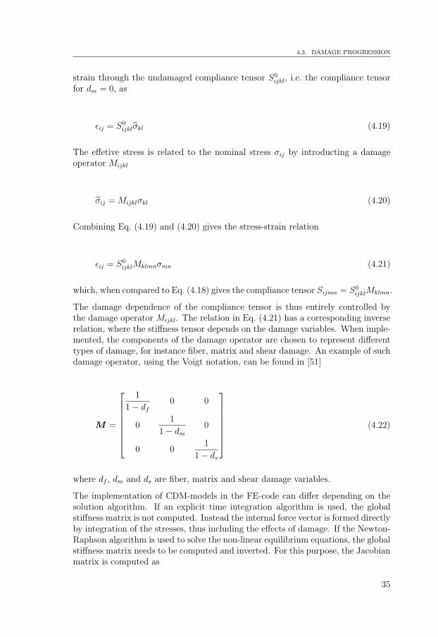
The conceptual studies also include a comparison of two different hybrid wingstructural concepts by analysis. Figure 14 shows the spar cross-sections of thetwo concepts and an all-composite baseline design. The comparison considers themass, structural behavior, strength, interaction between composite and aluminum,influence of thermal load and the significance of the altered requirements. Resultsfrom FE-analysis using the current requirements are shown in Fig. 18 and usingthe renewed requirements in Fig. 19. Based on these criteria concept 1 is chosenfor further analysis and structural testing.
The assessment of composite structures by analysis and detailed modeling is a com-plex task. The difficulties arise as a result of the variability of the material behaviorand failure modes described in Chapter 2. Typical engineering problems include:strength prediction in laminates, failure at fasteners and holes, delamination ini-tiation and growth, impact, ply drop-off regions, fatigue damage accumulation,out-of-plane stresses etc. In order to assess the structural response in an accurateway, the modeling techniques suited for industrial usage need to be developed.
21

CHAPTER 3. CERTIFICATION OF AIRCRAFT STRUCTURES
�
?
Aluminum alloy
Composite (CFRP)
Baseline Concept 1 Concept 2Upper skin
Lower skin
Spar
y
z
Figure 14: Cross-sections of the baseline design and the two hybrid concepts stud-ied.
3.2 Testing
Test verification with full-scale assemblies of complete airframe is mandatory inaircraft certification requirements. Verification through testing is required for staticstrength, damage tolerance and fatigue life.
For a metallic structure it is not possible to use the same test article to demonstrateboth static strength up to ultimate load conditions and fatigue life. The reasonis that high static loads will introduce plastic deformation in positions of stressconcentrations and leave beneficial residual stresses when unloaded, which candelay the initiation and growth of fatigue cracks. This is not acceptable since thetest is intended to show the safe fatigue life of all aircraft of the type tested, alsofor those individuals who will not experience high loads during its operational life.It is well established to use safety factors on the design service life to show safeoperational life for metallic structure. Factors between two and six have been usedhistorically.
Composite structure on the other hand behaves differently since such structure ismore susceptible for high loads which can initiate damages that may propagateunder service loads. Composite strength is also more susceptible for heat andmoisture content, which in most cases are impossible to impose on a full-scale testof a complete airframe. It is common to compensate the knock-down in staticstrength due to environmental influence by use of higher test loads than the designultimate loads.
It is also required to show flaw tolerance for manufacturing discrepancies and ser-vice damages such as undetected impact damages for composite structure underoperational loads. Also, the susceptibility for damage initiation and delaminationsgrowth under operational loads at stress concentrations is of concern in a test ver-ification perspective. There is an established knowledge that composites show alarger degree of variability in fatigue and damage growth properties [21]. Due tothe higher variability in composites compared to metals, higher safety factors thanthose used for metals are required. An alternative approach has been applied inthe aircraft industry in order to limit the long duration of testing time such factors
22

3.2. TESTING
will result in. The approach makes use of a smaller safety factor on life which iscompensated with an enlargement factor on loads. The factor on loads is knownas the load enhancement factor (LEF) and results in a shorter test duration. Theabove differences between composite and metal structure highlight a wide variety ofchallenges when a hybrid metal/composite structure are to be verified by full-scaletesting.
23


Constitutive modeling4
This chapter presents and discusses existing material modeling techniques for lami-nated composites. The models discussed include elastic behavior, damage initiationand damage progression, and are suited for numerical implementation with FEM.Some of the models are utilized in this thesis work in a modified form and othersare presented for the sake of overview. The framework for constitutive modelingof metals is well-established and is not treated in this work. Comprehensive de-scriptions can be found in [7]-[9] and the numerical implementation aspects areexplained in detail in [26].
4.1 Elastic behavior
As mentioned before, single composite laminae are often modeled as homogeneousorthotropic entities. This means that the characteristics of lamina micro-structure,i.e. fibers, matrix and fiber/matrix interface, are disregarded. Instead, the laminais idealized as a homogeneous continuum and assigned properties that are inde-pendent of position of the material point. Orthotropy, however, implies directiondependence of the properties. The linear elastic response of any material pointwithin a lamina can then be described by Hooke’s generalized law. The relationbetween the stress and the strain tensor then becomes
σij = Cijklεkl or εij = Sijklσkl (4.1)
where Cijkl and Sijkl are fourth-order tensors known as the stiffness and compliancetensors, respectively. Both tensors have the so-called minor and major symmetryproperties and are positive definite. The stress and strain tensors are also symmet-ric. If the coordinate axes are chosen as parallel to the material axes of orthotropy,i.e. 1, 2, 3 directions in Fig. 4, the second relation in Eq. (4.1) can be written inmatrix form using Voigt notation in terms of engineering elastic constants as
25

CHAPTER 4. CONSTITUTIVE MODELING
ε11
ε22
ε33
2ε12
2ε13
2ε23
=
1
E1
−ν21
E2
−ν31
E3
0 0 0
−ν12
E1
1
E2
−ν32
E3
0 0 0
−ν13
E1
−ν23
E2
1
E3
0 0 0
0 0 01
G12
0 0
0 0 0 01
G13
0
0 0 0 0 01
G23
σ11
σ22
σ33
σ12
σ13
σ23
(4.2)
where E1, E2, E3 are Young’s moduli in the principal material directions, νij, i 6= jare Poisson’s ratios and G12, G13, G23 are shear moduli.
The thickness of a lamina is small compared to its other dimensions. Based on this,it can be assumed that a lamina, which is exposed to in-plane loading, is in stateof plane stress, i.e. σ33 = σ13 = σ23 = 0. Consequently, Eq. (4.2) can be reduced to
ε11
ε22
2ε12
=
1
E1
−ν21
E2
0
−ν12
E1
1
E2
0
0 01
G12
σ11
σ22
σ12
(4.3)
The stiffness relation is then found as
σ11
σ22
σ12
=1
1− ν12ν21
E1 ν21E2 0
ν12E1 E2 0
0 0 (1− ν12ν21)G12
ε11
ε22
2ε12
or σ = Qε (4.4)
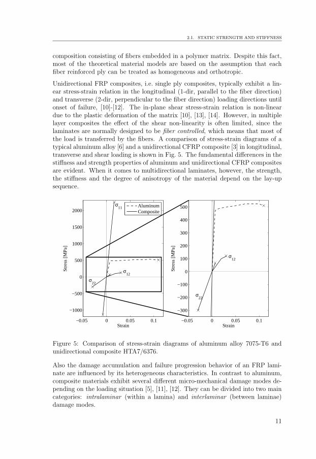
where σ is the stress matrix, ε is the strain matrix and Q is the lamina stiffnessmatrix. The bars indicate that the matrix components are expressed in the local,lamina coordinate system, i.e. 1, 2, 3 directions in Fig. 4. The equations presentedabove are valid for single laminae but they can be used to construct a relationbetween the applied in-plane loads and strains in a stacked laminate. The solution,known as the classical laminate plate theory (CLPT) is very briefly summarized
26
4.1. ELASTIC BEHAVIOR
here and the details can be found in [27]. This approach requires that the stackedlaminae are of uniform thickness and that they are rigidly bonded to each other.Further, the laminate plate thickness is considered to be small in comparison tothe other dimensions. Applying the Kirchhoff assumption, i.e. that the straightlines perpendicular to the midsurface of the plate remain straight, perpendicularand inextensible after the deformation, the laminate strain matrix can be writtenas
ε = ε0 + zκ (4.5)
where ε = [εx εy γxy]T is the matrix containing the laminate strains expressed in
the global coordinate system, ε0 = [εx0 εy0 γxy0]T is matrix containing the strains
of the middle surface expressed in the global coordinate system, κ = [κx κy κxy]T
is the curvature matrix and z is the coordinate in the thickness direction, measuredfrom the middle surface. Now, defining the cross sectional distributed force andmoment matrices as N = [Nx Ny Nxy]
T and M = [Mx My Mxy]T , and
considering equilibrium between these and the lamina stresses across the crosssection, the following is obtained
[NM
]=
[A B
B D
] [ε0
κ
](4.6)
where the so-called ABD-matrix is
[A, B, D
]=
n∑k=1
Qk
[(zk − zk−1), 1/2(z2
k − z2k−1), 1/3(z3
k − z3k−1)
](4.7)
with Qk = T kQkTTk beeing the stiffness matrix of kth lamina in the global coordi-
nate system, Qk being the lamina stiffness matrix as defined in Eq. (4.4), zk beingthe z-coordinate of the kth lamina and T k being the transformation matrix be-tween the lamina stresses in local and global coordinate systems. Given the laminaproperties, Q can be constructed and with the laminate stacking sequence infor-mation, the ABD-matrix can be obtained. For given set of forces and momentsEq. (4.6) can then be solved for ε0 and κ, which with Eq. (4.5) gives the strainsover the laminate cross-section. Finally, these strains can be transformed into localcoordinate strains using T and to local coordinate stresses using Eq. (4.4).
Both the lamina constitutive relation Eq. (4.2) and the laminate equation Eq. (4.6)are suitable for implementation in a FE-code. In the cases when each lamina ismodeled individually with at least one element through the thickness, the inverse of
27

CHAPTER 4. CONSTITUTIVE MODELING
the compliance matrix in Eq. (4.2) enters the element stiffness matrix in a straightforward manner. If the whole laminate section, or parts of it, are modeled withone element through the thickness, the ABD-matrix is used in the formulationof the element stiffness matrix. The summation in Eq. (4.7) is performed in thethickness direction over all layers within the element to obtain the ABD-matrix.Once the element nodal displacement are solved, the strains and stresses in eachlayer are obtained in the same way as described above. In commercial FE-codes,elements that use this formulation are usually referred to as layered elements andthey can be of different types, i.e. plane, plate, shell or solid elements. Regardlessof how the boundary-value problem is solved, the obtained lamina stresses in eachmaterial point can be compared to the local failure criteria.
The non-linear shear stress-strain relationship mentioned in Chapter 2, is oftenrepresented by a third-order polynomial [28]
γ12 =1
G12
τ12 + ατ 312 (4.8)
where α is a curve fitting parameter that is determined experimentally.
4.2 Failure criteria
Individual plies within a laminate exhibit different local failure behavior based onthe local stress state, as described in Chapter 2. Assuming linear elastic behavior,the stress and strain states can be obtained as functions of increasing applied loadusing the models in the previous section. In each individual lamina, intralaminarfailure criteria can then be applied to determine the failure initiation point andmaximal load-bearing capacity of the lamina. The failure criteria are commonlyexpressed in the form
fm(σij, εij, σij, εij) = 1 (4.9)
where σij and εij symbolically denote the unidirectional laminate strengths andfailure strains respectively and fm denotes the failure function of mode m. A vastnumber of different failure criteria has been developed over the years and some ofthem are reviewed in [29]. An assessment and comparison of predictive capabilitiesof a large number of failure criteria was conducted in [30] in a World-Wide FailureExercise (WWFE) and recommendations for designers were published. In thissection, some of the most commonly used criteria, as well as criteria utilized in thiswork, are presented.
28

4.2. FAILURE CRITERIA
4.2.1 Limit criteria
The maximum stress and maximum strain criteria belong to this group of criteria.According to the maximum stress criterion, failure initiation occurs when any of thelamina stresses in the material principal directions reaches its respective strength.This is expressed as
σ11
X= 1 where
X = XT if σ11 > 0X = −XC if σ11 < 0
(4.10a)
σ22
Y= 1 where
Y = YT if σ22 > 0Y = −YC if σ22 < 0
(4.10b)
|σ12|S12
= 1 (4.10c)
where XT and XC are unidirectional laminate tensile and compressive strengthin fiber direction, YT and YC are unidirectional laminate tensile and compressivestrength in transverse direction and S12 is lamina shear strength. The maximumstrain criterion is identical to Eq. (4.10) provided that the stresses are replaced withstrains and the strengths are replaced with lamina failure strains. It is evident thatthese criteria are based only on evaluation of the strength in the material principaldirections, i.e. no interaction between the stress/strain components is considered.
4.2.2 Polynomial criteria
These criteria have their origin in von Mises yield criterion for metals, which statesthat the initial yield occurs when the deviatoric strain energy reaches a certainvalue. This condition can be expressed by a singe polynomial function cf. Eq.(4.9) that signifies an effective stress quantity. Hill [31] extended this criterionfor ductile anisotropic materials which was then further modified for compositesby Azzi and Tsai [32]. The resulting polynomial expression is referred to as theTsai-Hill criterion and yields
(σ11
X
)2
+(σ22
Y
)2
+
(σ12
S12
)2
− σ11σ22
X2= 1 where
X = XT if σ11 > 0X = −XC if σ11 < 0Y = YT if σ22 > 0Y = −YC if σ22 < 0
(4.11)
29

CHAPTER 4. CONSTITUTIVE MODELING
The criterion considers the interaction between the stress components as well as thedifference in normal tensile and compressive strengths. A drawback is that one mustkeep track of the sign of the normal stress in order to insert the correct strengthinto the polynomial. However, the criterion is based on behavior of ductile metalsand takes no account of heterogeneity and diversity of failure modes in composites.Based on the lack of physical relevance for composites, the Tsai-Hill criterion hasreceived some criticism, for instance in [33].
Another, more general polynomial criterion, known as the Tsai-Wu criterion wasproposed in [34] and states that failure initiation occurs when
σ211
XT XC
+σ2
22
YT YC
+σ2
12
S212
−2F12σ11σ22 +(1
XT
− 1
XC
)σ11 +(1
YT
− 1
YC
)σ22 = 1 (4.12)
Besides the five already mentioned strength constants, the interaction materialparameter F12, which is obtained by a biaxial normal load test, is required. Thiscriterion suffers from the same drawback as the former one, namely that it makes nodistinction between the different failure modes in composites. Another drawback isthat the these criteria are independent of a superimposed hydrostatic stress, whichis typical for metals but not for composites. Both of the above criteria are derivedas special cases of a general polynomial criterion which can be expressed as
f = Fijσij + Fijσikσkj + ... = 1 (4.13)
where i, j = 1, 2 and Fij are material parameters.
4.2.3 Physically based criteria
In [35], the author starts with the general polynomial criterion in Eq. (4.13) andconsiders two extreme cases of a composite laminate: one with infinitely stiff fibers(matrix-controlled failure) and one with fiber-controlled failure. In each case,several terms cancel, leading to two separate polynomial expressions: one fiber-controlled and one matrix-controlled. The conclusion is that, when the anisotropyis an order of magnitude or greater, the decomposition of the criterion into fiberand matrix failure modes is necessary. The same conclusion can be drawn from as-sessment of the physical failure process described in Chapter 2. This has motivatedmany researchers to derive criteria based on physical characteristics of failure. Al-though the criteria are classified as physically based, they are often stated as amixture of limit and polynomial expressions where the different failure modes areseparated. A widely used 2D physical criterion, known as the Hashin criterionwas published in [36] and was later modified into a 3D form in [37]. This criterion
30
4.2. FAILURE CRITERIA
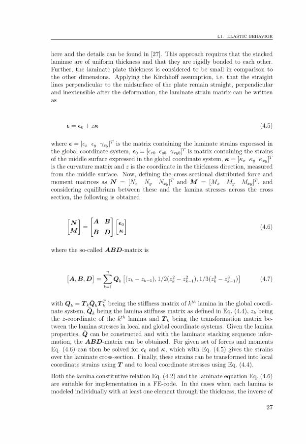
was originally intended for fatigue failure prediction but has also been used for theprediction of static failure. It yields
Tensile fiber failure (σ11 > 0)(σ11
XT
)2
+1
S212
(σ212 + σ2
13) = 1 (4.14a)
Compressive fiber failure (σ11 < 0)
−σ11
XT
= 1 (4.14b)
Tensile matrix failure (σ22 + σ33 > 0)
1
Y 2T
(σ22 + σ33)2 +
1
S223
(σ223 − σ22σ33) +
1
S212
(σ212 + σ2
13) = 1 (4.14c)
Compressive matrix failure (σ22 + σ33 < 0)
1
YC
[(YC
S23
)2
− 1
](σ22+σ33)+
1
4S223
(σ22+σ33)2+
1
S223
(σ223−σ22σ33)+
1
S212
(σ212+σ2
13) = 1
(4.14d)
In between the two Hashin publications, Yamada and Sun [38] proposed a criterionsuited for the fiber controlled laminates, i.e. laminates which are not controlled bythe transverse lamina strength Y . The criterion is similar to Eq. (4.11) if σ22 = 0and yields
(σ11
X
)2
+
(σ12
Sis
)2
= 1 whereX = XT if σ11 > 0X = −XC if σ11 < 0
(4.15)
and where Sis is the in-situ lamina shear strength determined from measurementin cross-ply laminates. Based on this expression, Chang and Chang [39] and Changand Lessard [40], developed another criterion, which includes shear non-linearity[28]. Further modifications, including the out-of-plane stresses were introduced byOlmedo and Santiuste [41] in the context of failure modeling of single-lap boltedjoints. This criterion is included in Paper 2 of this thesis, where it was utilized inFE-modeling of bolted joint failure. It yields
Tensile fiber failure (σ11 > 0)√√√√√√√(
σ11
XT
)2
+
τ 212
2G12
+3
4ατ 4
12
S212
2G12
+3
4αS4
12
+
τ 213
2G13
+3
4ατ 4
13
S213
2G13
+3
4αS4
13
= 1 (4.16a)
31

CHAPTER 4. CONSTITUTIVE MODELING
Compressive fiber failure (σ11 < 0)
−σ11
XC
= 1 (4.16b)
Matrix in-plane failure√√√√√√√(
σ22
Y
)2
+
τ 212
2G12
+3
4ατ 4
12
S212
2G12
+3
4αS4
12
+
τ 223
2G23
+3
4ατ 4
23
S223
2G23
+3
4αS4
23
= 1 whereY = YT if σ22 > 0Y = −YC if σ22 < 0
(4.16c)
Matrix out-of-plane failure√√√√√√√(
σ33
Z
)2
+
τ 213
2G13
+3
4ατ 4
13
S213
2G13
+3
4αS4
13
+
τ 223
2G23
+3
4ατ 4
23
S223
2G23
+3
4αS4
23
= 1 whereZ = ZT if σ33 > 0Z = −ZC if σ33 < 0
(4.16d)
Fiber-matrix shearing failure (σ11 < 0)√√√√√√√(
σ11
XC
)2
+
τ 212
2G12
+3
4ατ 4
12
S212
2G12
+3
4αS4
12
+
τ 213
2G13
+3
4ατ 4
13
S213
2G13
+3
4αS4
13
= 1 (4.16e)
where ZT and ZC are unidirectional laminate tensile and compressive strength inout-of-plane direction and α is the material parameter from Eq. (4.8). In Eq.(4.16a), the third term under the square root is due to the contribution from theout-of-plane shear stress to the fiber failure. If α = 0, and the shear strengthS12 = S13, the criterion reduces to the tensile fiber mode criterion proposed byHashin [37]. Originally, Chang and Chang [39] assumed that S12 used shouldbe the in-situ ply shear strength measured from a cross-ply laminate, since thatvalue may differ significantly from the strength measured from unidirectional plies.Matrix out-of-plane failure is considered by expanding the Hashin [37] criterionfor delamination initiation with the non-linear shear stress/strain behavior. TheHashin criterion Eq. (4.14) was also implemented in the context of bolted jointfailure in Paper 2 and it was found that the results were very close to those obtainedwith the criterion in Eq. (4.16).
The intralaminar criteria presented above are based on the distinction of the fiberand matrix dominated failure. However, the resulting quadratic polynomial ex-pressions are derived from phenomenological assumptions of stress interaction and
32

4.3. DAMAGE PROGRESSION
not on physical characteristics of failure. More elaborated models were proposedby Puck and Schurmann in [18] and [15], where attention was payed to criticalplanes where matrix cracks develop and interaction between the fibers and thematrix. Further development of Puck’s criterion was performed by Davila et al.in [42] involving critical planes for matrix cracks, determination of in-situ strengthusing fracture mechanics and fiber-matrix interaction in development of kinking.A 3D version of this criterion including shear non-linearity was developed in [43].
In [29], a summary of interlaminar criteria for delamination initiation is presented.These models are similar to the quadratic polynomial intralaminar criteria previ-ously presented. However, the interface failure initiation and progression is oftenmodeled with FEM by introducing interfacial elements between the plies. A sum-mary of available models is included in [29].
4.3 Damage progression
Once the state in a material point within a lamina, or between the laminae, hasmet a failure criterion, its load carrying capacity will decrease with further loading.Damage progression, signified by loss of the stiffness, will take place until theamount of dissipated energy has reached a critical value, whereupon final failureoccurs. In a laminate, where the plies are exposed to different stress states, thefailure of all plies will not occur simultaneously. Instead, when one ply has failed(first-ply failure (FPF)), redistribution of the load to the other plies will take place,which then may fail themselves. As the applied load is increased, the progressionof failure and damage takes place. The ultimate strength of a laminate is reachedwhen the load can not be further increased, i.e. last-ply failure (LPF).
A common modeling approach is to reduce the relevant terms of the lamina stiffnessmatrix depending on the failure mode. This is known as the ply-discount method,and it is used in this work in the context of bolt joint failure. The stiffness terms tobe reduced are chosen by micro-mechanical considerations but the level to whichthey are reduced is somewhat arbitrary. The simplest alternative is to reduce allterms to zero as soon as the failure criterion is met. Such degradation correspondsto a sudden brittle failure with no energy dissipation in the damage process. This isnot a very realistic assumption, since it has been confirmed in many experimentalstudies that the stress degrades gradually after the onset of failure. In their work,Zang and Rowland [44] and Tserpes et al. [45] concluded that the reduction of thestiffness matrix terms to zero gives a too severe degradation when compared toexperimental results. It also causes convergence problems in the FE-modeling ofbolts because the elements in the area of large contact pressure tend to becomehighly distorted. A more realistic set of degradation factors were introduced byTan [46] and extended by Camanho [47] to three dimensions. Similar factors wereused in [41], [44], [45], [48] all with good correlation to experimental results. Thesame degradation factors are used in this work and are shown in Table 1.
33

CHAPTER 4. CONSTITUTIVE MODELING
Failure mode E11 E22 E33 G12 G13 G23 ν12 ν13 ν23
Matrix failure - 0.4 0.4 - - 0.2 0 0 0Fiber failue 0.14 0.4 0.4 0.25 0.25 0.2 0 0 0Fiber-matrix shear - - - 0.25 0.25 - 0 0 -
Table 1: Degradation rules in different failure modes.
Alternative approaches to modeling damage and subsequent loss of stiffness incomposite materials have been developed in the context of continuum damage me-chanics (CDM). After the failure criterion is met, the damage development due toeach failure mechanism is typically controlled by a damage variable. The mate-rial stiffness properties are successively reduced depending on the current damagestate, which in turn depends on a chosen damage evolution law. This law is thusa key parameter in the framework of CDM. The choice of law is often based onsome kind of physical or energy-conserving ground. Usually, the damage variablehas a value of 0 at failure initiation and increases to 1 during the damage accumu-lation whereafter the material stiffness is considered exhausted. A large number ofCDM-models are published in the literature and some examples are found in [16],[49], [50]-[53]. The typical framework is based on the second law of thermodynam-ics, which is expressed through the Clausius-Duhem inequality [7]. Under relevantconditions this can be written as
(∂G
∂σij
− εij
)σij +
∂G
∂dm
dm ≥ 0 (4.17)
where G = G(σij, dm) is Gibbs free energy and dm is the damage variable of modem. Since the stress tensor can be chosen arbitrary, the expression in the parenthesismust be equal to zero which with Eq. (4.1) leads to
εij =∂G
∂σij
= Sijklσkl and∂G
∂dm
dm ≥ 0 (4.18)
The first expression implies that the compliance tensor depends on the damagevariables. Thus, as the damage accumulates during the failure process, the compli-ance changes. The inequality signifies that the energy dissipation due to the changeof damage state cannot be negative. Once Gibbs free energy has been chosen sothat the thermo-dynamic forces ∂G/∂dm are positive, the sufficient condition forfulfillment of the second law is that the damage variables are non-decreasing func-tions. Apart from being non-decreasing, the damage functions are specified by adamage evolution law that is often determined from phenomenological or energy-conserving considerations. The notion of damage is, in classical sense of continuumdamage mechanics, coupled to the loss of stress transmitting area. The remainingundamaged area is then subjected to effective stress σij, which is related to the
34
4.3. DAMAGE PROGRESSION
strain through the undamaged compliance tensor S0ijkl, i.e. the compliance tensor
for dm = 0, as
εij = S0ijklσkl (4.19)
The effetive stress is related to the nominal stress σij by introducting a damageoperator Mijkl
σij = Mijklσkl (4.20)
Combining Eq. (4.19) and (4.20) gives the stress-strain relation
εij = S0ijklMklmnσmn (4.21)
which, when compared to Eq. (4.18) gives the compliance tensor Sijmn = S0ijklMklmn.
The damage dependence of the compliance tensor is thus entirely controlled bythe damage operator Mijkl. The relation in Eq. (4.21) has a corresponding inverserelation, where the stiffness tensor depends on the damage variables. When imple-mented, the components of the damage operator are chosen to represent differenttypes of damage, for instance fiber, matrix and shear damage. An example of suchdamage operator, using the Voigt notation, can be found in [51]
M =
1
1− df
0 0
01
1− dm
0
0 01
1− ds
(4.22)
where df , dm and ds are fiber, matrix and shear damage variables.
The implementation of CDM-models in the FE-code can differ depending on thesolution algorithm. If an explicit time integration algorithm is used, the globalstiffness matrix is not computed. Instead the internal force vector is formed directlyby integration of the stresses, thus including the effects of damage. If the Newton-Raphson algorithm is used to solve the non-linear equilibrium equations, the globalstiffness matrix needs to be computed and inverted. For this purpose, the Jacobianmatrix is computed as
35

CHAPTER 4. CONSTITUTIVE MODELING
∂σ
∂ε= C +
∑m
∂C
∂dm
∂dm
∂ε(4.23)
where C is the damaged stiffness tensor.
The implemented material models are often demonstrated on regular coupons orspecimens with open hole tension or compression and they often seem to work well.Bearing failure of bolted joints, on the other hand, is problematic in the sense thatthe area of damage concentration is also the area of contact between the boltand the hole edge. A complete degradation of stiffness and the subsequent elementdeletion in the area of contact creates convergence problems and yields poor results.From a physical point of view and based on the experimental observations, materialremoval is unrealistic. The material that has failed due to the bearing failure modeseem to have some residual stiffness left but there is no obvious way to model thiskind of behavior and further research is required.
36

Finite element modeling5
In this chapter, the FE techniques used in this work are outlined. All simulationsare preformed with the commercial FE-program Abaqus [54]. Theoretical detailsand implementation technique background can be found in [26], [55], [56] andcomposite specific topics in [57], [58]. Two types of models are developed in thiswork: global shell models of the hybrid wing box structure and local solid modelsof bolted hybrid joints.
5.1 Modeling of bolted joints
In the appended Paper 2, the detailed modeling of a single shear lap, composite-aluminum joint with countersunk titanium fastener is performed. A large numberof studies of bolted joints with composite plates can be found in the literature [59].They range from two-dimensional models with rigid pins representing the bolt[48], [60], [61], to three-dimensional models with or without damage developmentin the composite [41], [44], [47], [58], [62]-[68]. These studies include parame-ters as bolt pretension, bolt clearance, the effect of countersunk/protruding boltheads, different failure initiation and damage progression models, by-pass load-ing, implicit/explicit solution methods etc. In the current work, this accumulatedknowledge is utilized to develop local detailed models of hybrid fastener installa-tions in the wing box. The response, in terms of a force-displacement curve, of alocal model is then assigned to line elements representing the fasteners in a globalmodel of the wing box. This is described in the next section. Before modeling theactual joint geometries in the wing box, the modeling method is first applied toa joint specimen of similar constitution, which has been tested in [69]. Figure 15shows the mesh and the applied loading.
Each ply in the CFRP plate is represented with one solid element in the thicknessdirection, see Fig. 16, while the aluminum plate is assigned a somewhat lower solidmesh density. Aluminum and titanium materials are assigned elasto-plastic modelswith isotropic hardening. The normal stress-strain behavior in the composite plateis modeled as linear orthotropic, cf. Eq. (4.2), up to failure and for the shearstress-strain relation, Eq. (4.8) is used. In order to implement Eq. (4.8) into theFE-model, the non-linear term is rewritten such that a numerically stable algorithm
37

CHAPTER 5. FINITE ELEMENT MODELING
Figure 15: FE-model of a single-bolted hybrid joint specimen.
Figure 16: Close-up view of the mesh in the composite plate around the fastener.
is obtained, as described in [54]. The shear stress at the end of the load incrementi is then given as a linear function of the shear strain
τ(i+1)12 = (1− d)G12γ
(i+1)12 (5.1)
where
d =3αG12(τ
(i)12 )2 − 2α(τ
(i)12 )3/γ
(i)12
1 + 3αG12(τ(i)12 )2
(5.2)
The parameter d can be seen as a damage parameter that degrades the initial shearmodulus G12 to its current value (1− d)G12.
The failure criterion employed is written in Eq. (4.16). After failure initiation,the material degradation is achieved with a ply-discount method by reduction of
38

5.1. MODELING OF BOLTED JOINTS
relevant stiffness parameters. The degradation factors used were established in [46]and [47]. The material model is implemented into Abaqus as a user-defined sub-routine, which is called by the solver in each increment. Further details about thefailure criterion and degradation factors can be found in Paper 2. The model alsoincludes a contact formulation with Coulomb friction for all relevant surfaces, withfrictional coefficients from [70]. The solution is obtained by a standard Newton-Raphson algorithm. In Fig. 17, the applied force-displacement curve obtained byexperiments in [69] is compared to curves resulting from the simulations. Threedifferent simulations are considered, one without composite damage and withoutmetal plasticity, one with metal plasticity but without composite damage, and onewith both. The effect of including composite damage in the simulation is apparentfrom this comparison.
0 0.2 0.4 0.6 0.8 1 1.2 1.4 1.6 1.80
2
4
6
8
10
12
14
16
18Bolt shear failure
u [mm]
F [
kN
]
Experiment AC6III
FE, no damage, no plasticity
FE, no damage and plasticity
FE, damage and plasticity
Figure 17: Comparison of the applied force-displacement curves obtained by ex-periments in [69] and results from simulations.
The current version of Abaqus does contain a progressive damage model for com-posite materials. It is based on CDM concept described in the previous chapterand uses the Hashin criterion to evaluate the initial failure. However, it is two-dimensional and not implemented for solid elements. In this work, an attempt wasmade to run a fastener model using continuum shell elements with the Abaqusprogressive damage model for the composite plate. The kinematic and constitutiveformulations for continuum shell elements [71] are identical to the conventional shellelements but their geometry is based on the three-dimensional solid description.Since these elements use reduced integration, it turned out that hourglass modeswere triggered over large part of the contact area and the solution was destroyed.The results obtained with the ply-discount method captured the experimentally
39

CHAPTER 5. FINITE ELEMENT MODELING
observed behavior of the specimen well. The predicted damage initiation pointconcurred with the one obtained in testing, while the joint failure point was some-what over-predicted. In the local models of the joints within the wing box, thepredicted failure load was the same as the design failure load of the fastener in allcases.
5.2 Structural modeling
In both appended papers, FE-models of the wing-like structure in Fig. 3 are de-veloped. The difference is that the structure in the conceptual studies consistsof only one box, i.e. the splice section is not included, and that several types ofcross-sections are considered. Also, in the conceptual studies, only pure bendingand twisting loads are applied.
The focus in the conceptual study models is the middle section of the wing box,i.e. the area between the ribs. The remaining parts of the structure are includedonly to capture the effects of thermally induced stresses. All parts of the struc-ture are modeled as their mid-surfaces with conventional shell elements in order toincrease the computational efficiency. For the composite plates, the layered formu-lation without progressive damage is used, cf. Chapter 4. Only the initial failureis considered, by means of the maximum strain and Tsai-Hill criteria. Fastenersare represented using Abaqus connector elements, from which the fastener loadsare extracted. These are two-node elements that impose a user-defined constraintbetween the nodes. The implementation is based on the use of Lagrange multi-plier technique [56]. In the FE-models of the conceptual study, the fasteners areassigned a linear elastic stiffness without any damage behavior, and are only usedto compute the transferred fastener load. Evaluation of static and fatigue failureis then handled by external programs. Contact conditions are modeled between allstructural parts using a penalty contact formulation. All models are solved usinga large displacement formulation and the Newton-Raphson algorithm. Figure 18shows the resulting stress in the middle sections of two models from the conceptualstudies. The figure illustrates the different structural behavior of the concepts.According to the current requirements, only aluminum components are allowedto buckle prior to the ultimate load level. It is also shown that the 90◦C case isthe worst case scenario for concept 1 and -30◦C for concept 2. This is a resultof the buckling requirement on this structural configuration. Figure 19 shows theresulting deformations within the frame of renewed requirements, where bucklingis allowed for all components and temperature requirement is modified. It is worthmentioning that, in this case, the worst case thermal load is the same for bothconcepts.
The cross-section of the wing box chosen for the testing is of concept 2 type, withspars, ribs and splice of aluminum bolted to skins made of composite. The purposeof the structural modeling of the wing box in Paper 2 is to simulate the conditions
40

5.2. STRUCTURAL MODELING
(Avg: 35%)
Multiple section points
S, Mises
+0.000e+00
+4.778e+01
+9.556e+01
+1.433e+02
+1.911e+02
+2.389e+02
+2.867e+02
+3.344e+02
+3.822e+02
+4.300e+02
+4.175e+03
(a) Concept 1, at 90◦C
(Avg: 35%)
Multiple section points
S, Mises
+0.000e+00
+4.778e+01
+9.556e+01
+1.433e+02
+1.911e+02
+2.389e+02
+2.867e+02
+3.344e+02
+3.822e+02
+4.300e+02
+2.221e+03
(b) Concept 2, at -50◦C
Figure 18: Buckling pattern of the middle sections of the two studied hybrid con-cepts, ultimate bending/twisting load and applied temperature, current require-ments.
in the testing and to include the local composite damage and metal plasticity in thefasteners. Several authors have developed methods to introduce non-linear fastenerbehavior in structural models. For example, Weyer et al. [72] used connectorelements available in the Abaqus to represent self-piercing rivets in an explicitcrash analysis. The modeling included elastic, plastic and damage behavior of asingle bolted metal sheet specimen. Gray and McCarhty [73] developed a methodusing beam elements connected to a rigid surface to represent the bolt, and shellelements to model the laminate plates of the joint. Bolt-hole clearance, bolt-torqueand friction between the plates were considered, but the damage dissipation inlaminates was not accounted for. The functionality of the model was demonstrated
41
CHAPTER 5. FINITE ELEMENT MODELING
(Avg: 35%)
Multiple section points
MSTRN
+0.000e+00
+1.333e−01
+2.667e−01
+4.000e−01
+5.333e−01
+6.667e−01
+8.000e−01
+9.333e−01
+1.067e+00
+1.200e+00
+4.369e+00
(a) Concept 1, at -30◦C
(Avg: 35%)
Multiple section points
S, Mises
+0.000e+00
+4.778e+01
+9.556e+01
+1.433e+02
+1.911e+02
+2.389e+02
+2.867e+02
+3.344e+02
+3.822e+02
+4.300e+02
+4.744e+03
(b) Concept 2, at -30◦C
Figure 19: Buckling pattern of the middle sections of the two studied hybrid con-cepts, ultimate bending/twisting load and applied temperature, new requirements.
on a three-bolt single-lap joint. Another efficient approach was developed by Grayand McCarthy [74], were a user-defined element was implemented in Abaqus. Themethod is capable of modeling non-linear behavior and failure of composite jointsbased on a semi-empirical approach. A joint with twenty fasteners was used forvalidation of the method. Ekh and Schon [75] made use of beam elements torepresent both bolt and laminates, and connector elements to account for bolt-holeclearance and friction. The model was suited for optimization of load transfer, butwas limited to single-column joints. A two-dimensional model of a steel-concretebeam with spring elements representing the shear connections was developed byWang and Chung [76]. A non-linear behavior of the springs, based on experimentaldata was utilized.
42
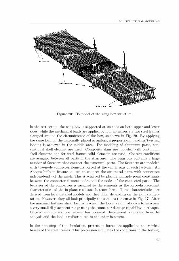
5.2. STRUCTURAL MODELING
Figure 20: FE-model of the wing box structure.
In the test set-up, the wing box is supported at its ends on both upper and lowersides, while the mechanical loads are applied by four actuators via two steel framesclamped around the circumference of the box, as shown in Fig. 20. By applyingthe same load on the diagonally placed actuators, a proportional bending/twistingloading is achieved in the middle area. For modeling of aluminum parts, con-ventional shell element are used. Composite skins are modeled with continuumshell elements and for steel frames solid elements are used. Contact conditionsare assigned between all parts in the structure. The wing box contains a largenumber of fasteners that connect the structural parts. The fasteners are modeledwith two-node connector elements placed at the center axis of each fastener. AnAbaqus built in feature is used to connect the structural parts with connectorsindependently of the mesh. This is achieved by placing multiple point constraintsbetween the connector element nodes and the nodes of the connected parts. Thebehavior of the connectors is assigned to the elements as the force-displacementcharacteristics of the in-plane resultant fastener force. These characteristics arederived from local detailed models and they differ depending on the joint configu-ration. However, they all look principally the same as the curve in Fig. 17. Afterthe maximal fastener shear load is reached, the force is ramped down to zero overa very small displacement range using the connector damage capability in Abaqus.Once a failure of a single fastener has occurred, the element is removed from theanalysis and the load is redistributed to the other fasteners.
In the first step of the simulation, pretension forces are applied to the verticalbraces of the steel frames. This pretension simulates the conditions in the testing,
43

CHAPTER 5. FINITE ELEMENT MODELING
where bolts are pre-torqued in order to hold the steel frame in position while theactuator loads are applied. In a subsequent step, a constant temperature of 70◦C isapplied to the entire box. In the final step, the actuator forces are applied as linearlyincreasing functions of the step time. At some point, the first fastener failure occursand load redistribution takes place. After that, the process progresses by failure ofthe neighboring fasteners. The sudden loss of load carrying capacity in the fastenerscreates local instabilities which in turn cause convergence difficulties in the solutionprocess. The problem is handled by introduction of artificial stabilizing measuresand local viscous damping. Figure 21 shows the redistribution of the fastener loadsdue to the progressive fastener failure in the splice section bolt rows.
0 16 32 48 640
0.5
1
1.5
2
2.5
3
3.5
x 104
Bolt nr
F [
N]
Skin−Splice bolt group
row 1 row 2 row 3 row 4
Failure onset
10 bolts failed
Figure 21: Progressive fastener failure in the splice section.
44

Outlook6
In this work, the focus is directed on the strength analyzes and modeling of a hybridstructure. The main concerns are the interaction of composite and aluminum partsand the different structural requirements they may comply to, and the detailedmodeling of the fastener installations. The modeling work is closely related to theongoing testing of the wing box structure described in this thesis. The next stepof the research effort is to evaluate the test results and to evaluate and comparethe outcome of the results from the analytical predictions. The emphasis is put onthe thermo-mechanical behavior, strength, stability, fatigue and damage tolerancecharacteristics.
In the analyzes, increased temperature resulted in a biaxial stress state in the fas-tener joints. It is unclear how this stress state affects the strength and fatiguelife of the hybrid joints and experimental investigations are currently conductedon coupon test specimens to gain more knowledge. There is a possibility that thecomposite is affected in a totally different way than aluminum is. Further develop-ment of modeling techniques, which include softening of the composite material infatigue loading, is needed in order to capture the conditions in the test. The testingon coupons is also intended to provide information about the scatter difference ofaluminum and composite in fatigue, which may give increased knowledge to re-vise load enhancement factors for structural testing. Both constant amplitude andspectrum loading are included in the coupon testing. The effects of elimination ofinsignificant load levels in the spectrum and truncation of overloads for composite,aluminum and the hybrid will be studied.
The wing box structure contains an impact damage and artificial delaminationsin the ply drop-off regions in the composite skin. Modeling work is currentlyconducted with the aim to simulate the impact event and subsequent loading in thestructure. Interlaminar and intralaminar damage are considered using continuumdamage models and cohesive elements. The artificial delaminations are modeledusing virtual crack closure technique.
The structural testing of the wing box conducted in this research is substantiallydifferent from the typical structural verification testing. The test of the wingbox is performed in order to assess the thermo-mechanical behavior of the hybridstructure and to find the critical features from static, fatigue and damage tolerantpoints of view. In the verification testing, the purpose is to evaluate whether or
45

CHAPTER 6. OUTLOOK
not a representative structure complies with the requirements under the prescribedterms of use. The inherent variability of both material properties and load spectraneed to be taken into account. This poses a problem for hybrid structures becauseof the mismatch of the variability between composite and aluminum. More researchon the scatter in critical composite structural features needs to be done in orderto establish more viable procedures for verification testing of hybrid structures.
46

Review of included papers7
Paper I
Conceptual studies of a composite-aluminum hybrid wing box demon-strator
This work presents a conceptual study of two different cross-section designs of ahybrid wing box structure. The structure is designed given the thermal and me-chanical loads and with respect to requirements, for static strength, fatigue andstability, currently used in the aircraft industry. The overall structural response isevaluated, as well as the local and structural failure modes. The resulting massesof the two concepts, subject to current requirements, are compared. Further, therequirements concerning allowable strains, allowable buckling load and given ther-mal loads are modified and another comparison is preformed. This comparison isperformed between the two concepts, but also between the two different require-ment set and their impact on the final masses of the concepts. Finally, one of theconcepts is chosen to be used in design of a test.
Paper II
Finite element modeling of mechanically fastened composite-aluminumjoints in aircraft structures
Mechanically fastened joints are widely used in structural design of aircraft. Dueto the large number of fasteners in the structure, detailed FE-modeling of thestructure including joints tends to be computationally expensive. In this paper,a methodology is developed in which the local hybrid joint behavior, includingdamage accumulation in composite and metal plasticity, is assessed first. Thisbehavior, including fastener failure, is then assigned to structural elements rep-resenting the bolts in a global structural model. This technique is applied to ahybrid composite-aluminum wing box structure exposed to thermal and mechani-cal loading. An FE-model of the wing box in the test setup is developed and the
47

CHAPTER 7. REVIEW OF INCLUDED PAPERS
progressive failure of bolted joints is studied. The initial joint stiffness predictedwith the local models agrees well with the semi-empirical stiffness commonly usedin the industry today. At higher loads, however, due to damage development inthe composite and aluminum plasticity, the force-displacement curve deflects fromthe linear. Simulations show that the fastener load distribution at high load levelsis affected by this and that linear fastener models produce inaccurate results. Itwas also shown that the thermally induced loads give a significant contribution tothe mechanical loads at considered temperatures.
48

Bibliography
[1] M. C. Y. Niu. Airframe structural design. Hong Kong Conmilit Press,Second edition, Hong Kong, 1999.
[2] R. S. Whitehead. Lessons learned for composite structures. The first NASAadvanced composites technology conference, Part I, 399-415, Seattle, 1990.
[3] MIL-HDBK-17-3F. Military handbook, polymer matrix composites. U.S.Department of Defense, 2000.
[4] J. Rouchon. Certification of large airplane composite structures - recentprogress and new trends in compliance philosophy. In 17th ICAS Congress,Stockholm, 1990.
[5] R. Talreja and C. V. Singh. Damage and failure of composite materials.Cambridge University Press, Cambridge, 2012.
[6] MMPDS-04. Metallic materials properties development and standardization(MMPDS). Federal Aviation Administration, 2006.
[7] N. S. Ottosen and M. Ristinmaa. The mechanics of constitutive modeling.Elsevier, Oxford, 2005.
[8] J. Lemaitre and J. L. Chaboche. Mechanics of solid materials. CambridgeUniversity Press, Cambridge, 1994.
[9] J. Lubliner. Plasticity theory. Macmillan, New York, 1990.
[10] V. V. Vasiliev and E. V. Morozov. Mechanics and analysis of compositematerials. Elsevier Science, First edition, Oxford, 2001.
[11] I. M. Daniel and O. Ishai. Engineering mechanics of composite materials.Oxford University Press, Oxford, 1994.
[12] R. M. Jones. Mechanics of composite materials. McGraw Hill, New York,1975.
[13] J. M. Hodgkinson. Mechanical testing of advanced fibre composites. Wood-head Publishing, First edition, Cambridge, 2000.
[14] A. K. Kaw. Mechanics of composite materials. CRC Press, Second edition,Boca Raton, 2006.
49

BIBLIOGRAPHY
[15] A. Puck and H. Schurmann. Failure analysis of frp laminates by means ofphysically based phenomenological models. Composites Science and Tech-nology, 62(12-13):1633–1662, 2002.
[16] A. Matzenmiller, J. Lubliner, and R. L. Taylor. A constitutive model foranisotropic damage in fiber-composites. Mechanics of Materials, 20(2):125–152, 1995.
[17] D. Hull and T. W. Clyne. An introduction to composite materials. Cam-bridge University Press, Second edition, Cambridge, 1996.
[18] A. Puck and H. Schurmann. Failure analysis of frp laminates by means ofphysically based phenomenological models. Composites Science and Tech-nology, 58(7):1045–1067, 1998.
[19] P. P. Camanho, C. G. Davila, S. T. Pinho, L. Iannucci, and P. Robinson.Prediction of in situ strengths and matrix cracking in composites under trans-verse tension and in-plane shear. Composites Part A: Applied Science andManufacturing, 37(2):165–176, 2006.
[20] R. S. Whitehead, H. P. Kan, R. Cordero, and E. S. Saether. Certificationtesting methodology for composite structure, Volume I: Data analysis andVolume II: Methodology development. Northrop Corporation, Hawthorne,1986.
[21] J. Rouchon. Fatigue and damage tolerance evaluation of structures: Thecomposite materials response. In 22th Plantema memorial lecture, 25th ICAFsymposium, Rotterdam, 2009.
[22] S. Suresh. Fatigue of materials. Cambridge University Press, Second edition,Cambridge, 1998.
[23] FAR 25. Airworthiness Standards: Transport Category Airplanes. FederalAviation Administration.
[24] MIL-STD-1530C. DoD Standard Practice, Aircraft Structural Integrity Pro-gram (ASIP). Aeronautical Systems Center, Wright-Patterson AFB, Ohio,2005.
[25] Defence Standard 00-970. Design and Airworthiness Requirements for ServiceAircraft. 1 - Fixed Wing Section 3 - Structure. UK Ministry of Defence.
[26] T. Belytschko, W. K. Liu, and B. Moran. Nonlinear finite elements forcontinua and structures. Wiley, Chichester, 2000.
[27] J. N. Reddy. Mechanics of laminated composite plates and shells: theoryand analysis. CRC Press, Second edition, Boca Raton, 2004.
[28] H. T. Hahn and S. W. Tsai. Nonlinear elastic behavior of unidirectionalcomposite laminates. Journal of Composite Materials, 7(1):102–118, 1973.
50

BIBLIOGRAPHY
[29] A. C. Orifici, I. Herszberg, and R. S. Thomson. Review of methodologies forcomposite material modelling incorporating failure. Composite Structures,86(1-3):194–210, 2008.
[30] M. J. Hinton, A. S. Kaddour, and P. D. Soden. Failure criteria in fibre-reinforced polymer composites. Elsevier, Oxford, 2004.
[31] R. Hill. The mathematical theory of plasticity. Oxford University Press,Oxford, 1950.
[32] V. D. Azzi and S. W. Tsai. Anisotropic strength of composites. ExperimentalMechanics, 5(9):283–288, 1965.
[33] L. J. Hart-Smith. The role of biaxial stresses in discriminating betweenmeaningful and illusory composite failure theories. McDonnell Douglas Cor-poration, Long Beach, 1991.
[34] S. W. Tsai and E. M. Wu. General theory of strength for anisotropic mate-rials. Journal of Composite Materials, 5:58–80, 1971.
[35] R. M. Christensen. Mechanics of composite materials. Dover Publications,New York, 2005.
[36] Z. Hashin and A. Rotem. A fatigue failure criterion for fiber reinforcedmaterials. Journal of Composite Materials, 7:448–464, 1973.
[37] Z. Hashin. Failure criteria for unidirectional fibre composites. Journal ofApplied Mechanics, 47:329–34, 1980.
[38] S. E. Yamada and C. T. Sun. Analysis of laminate strength and its distri-bution. Journal of Composite Materials, 12(3):275–284, 1978.
[39] F. K. Chang and K. Y. Chang. A progressive damage model for laminatedcomposites containing stress concentrations. Journal of Composite Materials,21(9):834–55, 1987.
[40] F. K. Chang and L. B. Lessard. Damage tolerance of laminated compos-ites containing an open hole and subject to compressive loadings: Part I -analysis. Journal of Composite Materials, 25(1):2–43, 1991.
[41] A. Olmedo and C. Santiuste. On the prediction of bolted single-lap compositejoints. Composite Structures, 94(6):2110–2117, 2012.
[42] C. G. Davila, P. P. Camanho, and C. A. Rose. Failure criteria for frp lami-nates. Composites Part A: Applied Science and Manufacturing, 39(4):323–345, 2005.
[43] S. T. Pinho, C. G. Davila, P. P. Camanho, L. Iannucci, and P. Robinson.Failure models and criteria for FRP under in-plane or three-dimensional stressstates including shear non-linearity. NASA/TM-2005-213530, Hampton,2005.
51
BIBLIOGRAPHY
[44] J. Zhang and J. Rowland. Damage modeling of carbon-fiber reinforced poly-mer composite pin-joints at extreme temperatures. Composite Structures,94(8):2314–2325, 2012.
[45] K. I. Tserpes, G. Labeas, P. Papanikos, and Th. Kermanidis. Strength pre-diction of bolted joints in graphite/epoxy composite laminates. CompositesPart B: Engineering, 33:521–529, 2002.
[46] S. C. Tan. A progressive failure model for composite laminates containingopenings. Journal of Composite Materials, 25(5):556–577, 1991.
[47] P. P. Camanho and F. L. Matthews. A progressive damage model for me-chanically fastened joints in composite laminates. Journal of CompositeMaterials, 33(24):2248–2280, 1999.
[48] M. L. Dano, E. Kamal, and G. Gendron. Analysis of bolted joints in com-posite laminates: Strains and bearing stiffness predictions. Composite Struc-tures, 79(4):562–570, 2007.
[49] P. Maimi, P. P. Camanho, J. A. Mayugo, and C. G. Davila. A continuumdamage model for composite laminates: Part I - constitutive model. Me-chanics of Materials, 39(10):897–908, 2007.
[50] P. Maimi, P. P. Camanho, J. A. Mayugo, and C. G. Davila. A continuumdamage model for composite laminates: Part II - computational implemen-tation and validation. Mechanics of Materials, 39(10):909–919, 2007.
[51] I. Lapczyk and J. A. Hurtado. Progressive damage modeling in fiber-reinforced materials. Composites Part A: Applied Science and Manufac-turing, 38(11):2333–2341, 2002.
[52] S. T. Pinho, L. Iannucci, and P. Robinson. Physically-based failure modelsand criteria for laminated fibre-reinforced composites with emphasis on fibrekinking: Part I: Development. Composites Part A: Applied Science andManufacturing, 37(1):63–73, 2006.
[53] S. T. Pinho, L. Iannucci, and P. Robinson. Physically-based failure modelsand criteria for laminated fibre-reinforced composites with emphasis on fibrekinking: Part II: FE implementation. Composites Part A: Applied Scienceand Manufacturing, 37(5):766–777, 2006.
[54] ABAQUS. Analysis user’s manual, version 6.11., 2011. Dassault Systemes,Providence.
[55] T. J. R. Huges. The finite element method - Linear static and dynamic finiteelement analysis. Dover Publications, New York, 2000.
[56] R. D. Cook, D. S. Malkus, M. E. Plesha, and R. J. Witt. Concepts andapplications of finite element analysis. John Wiley, Hoboken, 2002.
[57] F. L. Matthews, G. A. O. Davies, D. Hitchings, and C. Soutis. Finite element
52

BIBLIOGRAPHY
modelling of composite materials and structures. Woodhead Publishing,Cambridge, 2000.
[58] O. O. Ochoa and J. N. Reddy. Finite element analysis of composite laminates.Kluwer Academic Publishers, Waterloo, 1992.
[59] P. P. Camanho and F. L. Matthews. Stress analysis and strength predictionof mechanically fastened joints in frp: a review. Composites Part A: AppliedScience and Manufacturing, 28(6):529–547, 1997.
[60] M. L. Dano, G. Gendron, and A. Picard. Stress and failure of mechanicallyfastened joints in composite laminates. Composite Structures, 50(3):287–296,2000.
[61] Y. Xiao and T. Ishikawa. Bearing strength and failure behavior of boltedcomposite joints (Part II: modeling and simulation). Composites Scienceand Technology, 65(7-8):1032–1043, 2005.
[62] C. Huhne, A. K. Zerbst, G. Kuhlmann, C. Steenbock, and R. Rolfes. Pro-gressive damage analysis of composite bolted joints with liquid shim layersusing constant and continuous degradation models. Composite Structures,92(2):189–200, 2010.
[63] C. T. McCarthy, M. A. McCarthy, and V. P. Lawlor. Progressive dam-age analysis of multi-bolt composite joints with variable bolt-hole clearances.Composites Part B: Engineering, 36(4):290–305, 2005.
[64] P. Linde, J. Pleitner, H. De Boer, and C. Carmone. Modelling and simulationof fiber metal laminates. In ABAQUS Users Conference, Boston, 2004.
[65] T. Ireman. Three-dimensional stress analysis of bolted single-lap compositejoints. Composite Structures, 43(3):195–216, 1998.
[66] F. Rosales-Iriarte, N. A. Fellows, and J. F. Durodola. Failure prediction incarbon composites subjected to bearing versus bypass loading. Journal ofComposite Materials, 46(15):1859–1878, 2012.
[67] B. Egan, C. T. McCarthy, M. A. McCarthy, P. J. Gray, and R. M. Frizzell.Modelling a single-bolt countersunk composite joint using implicit and ex-plicit finite element analysis. Computational Materials Science, 64:203–208,2012.
[68] M. Chishti, C. H. Wang, R. S. Thomson, and A. C. Orifici. Numericalanalysis of damage progression and strength of countersunk composite joints.Composite Structures, 94(2):643–653, 2012.
[69] T. Ireman, R. Ranvik, and I. Eriksson. On damage development in mechan-ically fastened composite laminates. Composite Structures, 49(2):151–171,2000.
53

BIBLIOGRAPHY
[70] J. Schon. Coefficient of friction for aluminum in contact with a carbon fiberepoxy composite. Tribology International, 33(5):395–404, 2004.
[71] R. de Borst, M. A. Chrisfield, J. J. C. Remmers, and C. V. Verhoosel. Non-linear finite element analysis of solids and structures. John Wiley, Secondedition, Chichester, 2012.
[72] S. Weyer, H. Hooputra, and F. Zhou. Modeling of self-piercing rivets usingfasteners in crash analysis. In ABAQUS Users Conference, Boston, 2006.
[73] P. J. Gray and C. T. McCarthy. A global bolted joint model for finite elementanalysis of load distributions in multi-bolt composite joints. Composites PartB: Engineering, 41(4):317–325, 2010.
[74] P. J. Gray and C. T. McCarthy. A highly efficient user-defined finite ele-ment for load distribution analysis of large-scale bolted composite structures.Composites Science and Technology, 71(12):1517–1527, 2011.
[75] J. Ekh and J. Schon. Finite element modeling and optimization of load trans-fer in multi-fastener joints using structural elements. Composite Structures,82(2):245–256, 2008.
[76] A. J. Wang and K. F. Chung. Advanced finite element modelling of perfo-rated composite beams with flexible shear connectors. Engineering Struc-tures, 30(10):2724–2738, 2008.
54