Embed Size (px)
Citation preview

Universitat Politecnica de CatalunyaDepartment of Signal Theory and Communication
Radio Communication Group
Łukasz Budzisz
Stream Control Transmission Protocol (SCTP),a proposal for seamless handover managementat the transport layer in heterogeneous wireless
networks.
Barcelona, 2009

This dissertation investigates and evaluates the idea of handling mobility at the transport layer,using mobile Stream Control Transmission Protocol (mSCTP) as an example of a handover transportlayer protocol.
To this end, (the first part of) this thesis provides the reader with a necessary background for IPmobility-related aspects, surveying detailedly the most popular of the existing solutions. Providedoverview includes Mobile IP (MIP) and its most important derivatives to represent the network-layer-based schemes, as well as Session Initiation Protocol (SIP) as an example of an application-layer approach. The details of the most important transport layer solutions are given on continua-tion, along with the motivation for the development of such mobility management schemes. Amongpresented transport-layer approaches, the one based on the mSCTP is chosen as a representative forthe analysis performed in this dissertation. This choice is additionally motivated by two inter-esting features that SCTP protocol introduces, and that are interesting in the context of handoverapplications: multihoming and multistreaming (to some extent).
(Still in the introductory part) a detailed state-of-the-art of the SCTP protocol is provided, stress-ing its signaling background and original scope of use that did not consider mobility related ap-plication. The described transition from the signaling to a general purpose transport protocol illus-trates the dynamics of the development of this relatively recent proposal, and explains why SCTPis currently one of the most interesting innovative transport protocols.
The core of this dissertation outlines major mobility-related considerations in the context of fu-ture heterogeneous wireless networks, identifying all important handover scenarios, and specifyingthe most representative one to conduct the proposed analysis. Several transport-layer handoverschemes based on SCTP are analyzed in the selected scenario. First of the discussed schemes, pro-vided also as a reference model for evaluations presented in the following sections of this work,reuses the standard SCTP failover, a mechanism originally devised to increase protocol robustness.
Next, the details of transport-layer loadsharing are explained, to facilitate the introduction of themSCTP-CMT-PF handover scheme, an essential improvement for transport layer mobility suggestedby this work. The devised proposal incorporates one of the most popular loadsharing schemes pro-vided for SCTP, the Concurrent Multipath Transfer (CMT), that originally does not target wirelessnetworks. Evaluation exposes the main challenges of such a design, pointing out the most importantconstraints limiting its scope of application.
Finally, a quantitative comparison of all identified mSCTP-based handover schemes and two ofthe most representative network-layer solutions is given in a series of analysis that involves mobilitymodels of different grade of complexity.

Universitat Politecnica de CatalunyaDepartment of Signal Theory and Communication
Radio Communication Group
PhD Thesis
Stream Control Transmission Protocol (SCTP),a proposal for seamless handover managementat the transport layer in heterogeneous wireless
networks.
by
Łukasz Budzisz
Barcelona, 2009

c© 2009 Łukasz BudziszAll Rights Reserved

Contents
1 Introduction 11.1 Problem statement . . . . . . . . . . . . . . . . . . . . . . . . . . . . . . . . . . . . . . . 11.2 Motivation . . . . . . . . . . . . . . . . . . . . . . . . . . . . . . . . . . . . . . . . . . . . 3
2 Mobility management 52.1 Definitions . . . . . . . . . . . . . . . . . . . . . . . . . . . . . . . . . . . . . . . . . . . . 52.2 Approaches to mobility management . . . . . . . . . . . . . . . . . . . . . . . . . . . . 8
2.2.1 Sub-network layer mobility issues . . . . . . . . . . . . . . . . . . . . . . . . . . 82.2.2 Network-layer schemes . . . . . . . . . . . . . . . . . . . . . . . . . . . . . . . . 82.2.3 Transport-layer schemes . . . . . . . . . . . . . . . . . . . . . . . . . . . . . . . . 112.2.4 Application-layer schemes . . . . . . . . . . . . . . . . . . . . . . . . . . . . . . . 14
2.3 Conclusions . . . . . . . . . . . . . . . . . . . . . . . . . . . . . . . . . . . . . . . . . . . 15
3 SCTP for transport-layer mobility 173.1 SCTP overview . . . . . . . . . . . . . . . . . . . . . . . . . . . . . . . . . . . . . . . . . 17
3.1.1 Protocol basics . . . . . . . . . . . . . . . . . . . . . . . . . . . . . . . . . . . . . 183.1.2 New protocol features . . . . . . . . . . . . . . . . . . . . . . . . . . . . . . . . . 233.1.3 Protocol extensions . . . . . . . . . . . . . . . . . . . . . . . . . . . . . . . . . . . 243.1.4 Summary . . . . . . . . . . . . . . . . . . . . . . . . . . . . . . . . . . . . . . . . 25
3.2 SCTP state of the art in research . . . . . . . . . . . . . . . . . . . . . . . . . . . . . . . 253.2.1 Taxonomy . . . . . . . . . . . . . . . . . . . . . . . . . . . . . . . . . . . . . . . . 253.2.2 SCTP research analysis . . . . . . . . . . . . . . . . . . . . . . . . . . . . . . . . 30
3.3 Mobility implications . . . . . . . . . . . . . . . . . . . . . . . . . . . . . . . . . . . . . . 343.3.1 Related work . . . . . . . . . . . . . . . . . . . . . . . . . . . . . . . . . . . . . . 373.3.2 mSCTP use cases . . . . . . . . . . . . . . . . . . . . . . . . . . . . . . . . . . . . 39
3.4 Conclusions . . . . . . . . . . . . . . . . . . . . . . . . . . . . . . . . . . . . . . . . . . . 49
4 Failover as a basic handover scheme 514.1 Description of the SCTP failover mechanism . . . . . . . . . . . . . . . . . . . . . . . . 514.2 Reference study: analytical estimation of failover time . . . . . . . . . . . . . . . . . . 54
4.2.1 Best-worst case analysis . . . . . . . . . . . . . . . . . . . . . . . . . . . . . . . . 564.2.2 Estimation example . . . . . . . . . . . . . . . . . . . . . . . . . . . . . . . . . . 564.2.3 Estimation verification . . . . . . . . . . . . . . . . . . . . . . . . . . . . . . . . . 59
4.3 Failover as a basic mechanism to provide mobility . . . . . . . . . . . . . . . . . . . . . 614.3.1 Main parameters . . . . . . . . . . . . . . . . . . . . . . . . . . . . . . . . . . . . 614.3.2 Performance evaluation . . . . . . . . . . . . . . . . . . . . . . . . . . . . . . . . 71
4.4 Conclusions . . . . . . . . . . . . . . . . . . . . . . . . . . . . . . . . . . . . . . . . . . . 80
5 Improving handover with transport-layer loadsharing 835.1 Related work on transport-layer loadsharing with SCTP . . . . . . . . . . . . . . . . . 83
5.1.1 Concurrent multipath transfer . . . . . . . . . . . . . . . . . . . . . . . . . . . . 845.1.2 Scheduling algorithms . . . . . . . . . . . . . . . . . . . . . . . . . . . . . . . . . 855.1.3 Taxonomy . . . . . . . . . . . . . . . . . . . . . . . . . . . . . . . . . . . . . . . . 85
5.2 CMT to improve transport layer mobility: the mSCTP-CMT scheme . . . . . . . . . . 86
i

5.2.1 Scenario description . . . . . . . . . . . . . . . . . . . . . . . . . . . . . . . . . . 865.2.2 Analytical model . . . . . . . . . . . . . . . . . . . . . . . . . . . . . . . . . . . . 895.2.3 Basic performance evaluation . . . . . . . . . . . . . . . . . . . . . . . . . . . . . 905.2.4 Extended performance evaluation . . . . . . . . . . . . . . . . . . . . . . . . . . 101
5.3 Future work . . . . . . . . . . . . . . . . . . . . . . . . . . . . . . . . . . . . . . . . . . . 1075.3.1 ABC in slow start . . . . . . . . . . . . . . . . . . . . . . . . . . . . . . . . . . . . 1075.3.2 More frequent link probing schemes . . . . . . . . . . . . . . . . . . . . . . . . . 108
5.4 Conclusions . . . . . . . . . . . . . . . . . . . . . . . . . . . . . . . . . . . . . . . . . . . 108
6 Extended mobility analysis 1096.1 Preeliminaries . . . . . . . . . . . . . . . . . . . . . . . . . . . . . . . . . . . . . . . . . . 110
6.1.1 Scenario description . . . . . . . . . . . . . . . . . . . . . . . . . . . . . . . . . . 1106.1.2 Analyzed handover schemes . . . . . . . . . . . . . . . . . . . . . . . . . . . . . 1106.1.3 Simulation parameters . . . . . . . . . . . . . . . . . . . . . . . . . . . . . . . . . 113
6.2 Analysis results . . . . . . . . . . . . . . . . . . . . . . . . . . . . . . . . . . . . . . . . . 1156.2.1 Simple scenario (n = 1) . . . . . . . . . . . . . . . . . . . . . . . . . . . . . . . . . 1156.2.2 More complex mobility pattern (n = 3) - part 1 . . . . . . . . . . . . . . . . . . . 1176.2.3 More complex mobility pattern (n = 3) - part 2 . . . . . . . . . . . . . . . . . . . 122
6.3 Conclusions . . . . . . . . . . . . . . . . . . . . . . . . . . . . . . . . . . . . . . . . . . . 122
7 Conclusions 1297.1 Summary . . . . . . . . . . . . . . . . . . . . . . . . . . . . . . . . . . . . . . . . . . . . . 1297.2 Most important remarks . . . . . . . . . . . . . . . . . . . . . . . . . . . . . . . . . . . . 1307.3 Future work . . . . . . . . . . . . . . . . . . . . . . . . . . . . . . . . . . . . . . . . . . . 130
A SCTP support in ns-2 simulator 133A.1 Introduction . . . . . . . . . . . . . . . . . . . . . . . . . . . . . . . . . . . . . . . . . . . 133A.2 Implementation details . . . . . . . . . . . . . . . . . . . . . . . . . . . . . . . . . . . . . 135
A.2.1 SCTP module . . . . . . . . . . . . . . . . . . . . . . . . . . . . . . . . . . . . . . 135A.2.2 State of the art for wireless environments and mobility support in ns-2 . . . . 137A.2.3 Multihoming in wireless scenarios . . . . . . . . . . . . . . . . . . . . . . . . . . 139A.2.4 Proposed solution . . . . . . . . . . . . . . . . . . . . . . . . . . . . . . . . . . . 140
A.3 List of the modified files . . . . . . . . . . . . . . . . . . . . . . . . . . . . . . . . . . . . 142
Bibliography 143
Index 152
ii
List of Figures
1.1 Heterogeneous RANs scenario. . . . . . . . . . . . . . . . . . . . . . . . . . . . . . . . . 21.2 Dissertation scheme. . . . . . . . . . . . . . . . . . . . . . . . . . . . . . . . . . . . . . . 3
2.1 Mobility scenario. . . . . . . . . . . . . . . . . . . . . . . . . . . . . . . . . . . . . . . . . 52.2 Mobile IPv4 architecture and operations. . . . . . . . . . . . . . . . . . . . . . . . . . . 92.3 Mobile IPv6 architecture and operations. . . . . . . . . . . . . . . . . . . . . . . . . . . 102.4 mSCTP architecture and operations. . . . . . . . . . . . . . . . . . . . . . . . . . . . . . 132.5 SIP architecture and operations. . . . . . . . . . . . . . . . . . . . . . . . . . . . . . . . 14
3.1 SCTP PDU structure. . . . . . . . . . . . . . . . . . . . . . . . . . . . . . . . . . . . . . . 183.2 Chunk details. . . . . . . . . . . . . . . . . . . . . . . . . . . . . . . . . . . . . . . . . . . 183.3 SCTP association setup. . . . . . . . . . . . . . . . . . . . . . . . . . . . . . . . . . . . . 203.4 SCTP association release. . . . . . . . . . . . . . . . . . . . . . . . . . . . . . . . . . . . . 213.5 SCTP multihoming. . . . . . . . . . . . . . . . . . . . . . . . . . . . . . . . . . . . . . . . 233.6 SCTP multistreaming. . . . . . . . . . . . . . . . . . . . . . . . . . . . . . . . . . . . . . 243.7 Graphical illustration of proposed taxonomy. . . . . . . . . . . . . . . . . . . . . . . . . 273.8 Annual distribution of all published articles. . . . . . . . . . . . . . . . . . . . . . . . . 313.9 Number of articles within each category. . . . . . . . . . . . . . . . . . . . . . . . . . . 323.10 Annual distribution of all articles within each dimension. . . . . . . . . . . . . . . . . 353.11 Scatter plot of all handover-related articles. . . . . . . . . . . . . . . . . . . . . . . . . . 383.12 Scenario A – The IP address is not changed in the handover process. . . . . . . . . . . 403.13 Scenario B – Single-homed MN. . . . . . . . . . . . . . . . . . . . . . . . . . . . . . . . 403.14 mSCTP handover signaling for a single-homed MN. . . . . . . . . . . . . . . . . . . . 413.15 Optimized mSCTP handover scheme for a single-homed MN. . . . . . . . . . . . . . . 433.16 Scenario C – Single-homed CN, Dual-homed MN. . . . . . . . . . . . . . . . . . . . . . 443.17 mSCTP handover signaling for the asymmetric scenario. . . . . . . . . . . . . . . . . . 453.18 mSCTP handover scheme for the asymmetric scenario with different handover policies. 463.19 Scenario D – Dual-homed CN, Dual-homed MN. . . . . . . . . . . . . . . . . . . . . . 49
4.1 SCTP failover mechanism. . . . . . . . . . . . . . . . . . . . . . . . . . . . . . . . . . . . 524.2 The last SACK offset. . . . . . . . . . . . . . . . . . . . . . . . . . . . . . . . . . . . . . . 544.3 Different SCTP implementations behavior. . . . . . . . . . . . . . . . . . . . . . . . . . 554.4 Simulation scenario. . . . . . . . . . . . . . . . . . . . . . . . . . . . . . . . . . . . . . . 574.5 First timeout retransmission scheme. . . . . . . . . . . . . . . . . . . . . . . . . . . . . . 584.6 Comparison of the normalized failover time in long-thin net-works. . . . . . . . . . . 604.7 Simulation topology. . . . . . . . . . . . . . . . . . . . . . . . . . . . . . . . . . . . . . . 614.8 Ideal channel model. . . . . . . . . . . . . . . . . . . . . . . . . . . . . . . . . . . . . . . 624.9 Influence of PMR parameter. . . . . . . . . . . . . . . . . . . . . . . . . . . . . . . . . . . 634.10 Influence of PMR and cwnd evolution in the moment when the failure occurred. . . . 644.11 Influence of RTOMin parameter for failover latency. . . . . . . . . . . . . . . . . . . . . . 664.12 Influence of SACK delay parameter for failover latency. . . . . . . . . . . . . . . . . . . 694.13 Dynamic channel model. . . . . . . . . . . . . . . . . . . . . . . . . . . . . . . . . . . . . 734.14 SCTP failover performance in static channel conditions. . . . . . . . . . . . . . . . . . 74
iii
4.15 SCTP failover performance in a scenario with deteriorating primary path and staticchannel conditions on the backup path. . . . . . . . . . . . . . . . . . . . . . . . . . . . 75
4.16 SCTP failover performance in a dynamic changing channel on each path. . . . . . . . 774.17 Influence of ARQ on the SCTP failover performance - average file transfer time. . . . 784.18 Influence of ARQ on the SCTP failover performance - average number of primary
path changes. . . . . . . . . . . . . . . . . . . . . . . . . . . . . . . . . . . . . . . . . . . 81
5.1 Scatter plot of all loadsharing-related articles. . . . . . . . . . . . . . . . . . . . . . . . 865.2 Proposed CMT scenario. . . . . . . . . . . . . . . . . . . . . . . . . . . . . . . . . . . . . 875.3 mSCTP-CMT handover scheme. . . . . . . . . . . . . . . . . . . . . . . . . . . . . . . . 885.4 Performance comparison of all SCTP versions for bwratio = 4, and tdwell = 40 s. . . . . 915.5 Comparison in function of dwelling time. . . . . . . . . . . . . . . . . . . . . . . . . . . 935.6 Rbuf size constraints. . . . . . . . . . . . . . . . . . . . . . . . . . . . . . . . . . . . . . . 955.7 Smoothing effect. . . . . . . . . . . . . . . . . . . . . . . . . . . . . . . . . . . . . . . . . 975.8 Influence of the retransmission policy RtxCwnd on the mSCTP-CMT behavior. . . . . 985.9 Comparison for different RTT values in function of dwelling time. . . . . . . . . . . . 1025.10 Rbuf size constraints for different RTT values. . . . . . . . . . . . . . . . . . . . . . . . 1045.11 Performance comparison of all SCTP versions for bwratio = 4, and tdwell = 40 s. . . . . 1065.12 Failure detection in CMT-PF with frequent line probing. . . . . . . . . . . . . . . . . . 107
6.1 Scenario under test. . . . . . . . . . . . . . . . . . . . . . . . . . . . . . . . . . . . . . . . 1096.2 Mobility model for the presented analysis. . . . . . . . . . . . . . . . . . . . . . . . . . 1106.3 Comparison of various handover schemes in a simple scenario. . . . . . . . . . . . . . 1156.4 Comparison of various handover schemes for different values of δ in a scenario with
pattern 2-2 and without losses. . . . . . . . . . . . . . . . . . . . . . . . . . . . . . . . . 1186.5 Comparison of various handover schemes for different values of δ in a scenario with
pattern 2-2, and 2% of losses. . . . . . . . . . . . . . . . . . . . . . . . . . . . . . . . . . 1206.6 Comparison of various handover schemes for different values of δ in a scenario with
pattern 1-2 and without losses. . . . . . . . . . . . . . . . . . . . . . . . . . . . . . . . . 1236.7 Comparison of various handover schemes for different values of δ in a scenario with
pattern 1-2 and 2% of losses. . . . . . . . . . . . . . . . . . . . . . . . . . . . . . . . . . 125
A.1 Basic network components in ns-2. . . . . . . . . . . . . . . . . . . . . . . . . . . . . . . 134A.2 Multihomed node. . . . . . . . . . . . . . . . . . . . . . . . . . . . . . . . . . . . . . . . 136A.3 Wireless channel model - ARQLinearErr link. . . . . . . . . . . . . . . . . . . . . . . . 141
iv

List of Tables
2.1 Summary of network-layer mobility proposals. . . . . . . . . . . . . . . . . . . . . . . . 122.2 Comparison of different mobility management approaches. . . . . . . . . . . . . . . . 15
3.1 List of chunk types. . . . . . . . . . . . . . . . . . . . . . . . . . . . . . . . . . . . . . . . 193.2 Comparison of transport-layer protocols . . . . . . . . . . . . . . . . . . . . . . . . . . . 263.3 Summary of mSCTP application scenarios. . . . . . . . . . . . . . . . . . . . . . . . . . 50
4.1 Failover time estimation boundaries . . . . . . . . . . . . . . . . . . . . . . . . . . . . . 564.2 Default set of SCTP parameters . . . . . . . . . . . . . . . . . . . . . . . . . . . . . . . . 624.3 Recommended values of SCTP parameters in handover context . . . . . . . . . . . . . 724.4 Simulation parameters for failover evaluation . . . . . . . . . . . . . . . . . . . . . . . 72
5.1 Basic simulation parameters . . . . . . . . . . . . . . . . . . . . . . . . . . . . . . . . . . 895.2 Parameters modified for further evaluation of mSCTP-CMT . . . . . . . . . . . . . . . 101
6.1 Mobility patterns . . . . . . . . . . . . . . . . . . . . . . . . . . . . . . . . . . . . . . . . 1106.2 Failover-based mSCTP handover scheme details . . . . . . . . . . . . . . . . . . . . . . 1116.3 mSCTP handover scheme details . . . . . . . . . . . . . . . . . . . . . . . . . . . . . . . 1116.4 mSCTP-CMT-PF handover scheme details . . . . . . . . . . . . . . . . . . . . . . . . . . 1126.5 mSCTP-CMT handover scheme details . . . . . . . . . . . . . . . . . . . . . . . . . . . 1126.6 MIPv4RO network-layer handover scheme details . . . . . . . . . . . . . . . . . . . . . 1136.7 MIPv6 network-layer handover scheme details . . . . . . . . . . . . . . . . . . . . . . . 1136.8 Simulation parameters for comparison with the network layer schemes . . . . . . . . 114
A.1 Most important wireless networks models for ns-2. . . . . . . . . . . . . . . . . . . . . 138
v

vi

Acknowledgements
I have to first thank my advisor, Dr. Ramon Ferrus, for being an exceptional advisor. His abilityto ask the right questions and his incredible patience and attention to detail have never ceased tosurprise me. He was always able to make time for me, even if I just walked into his office withoutany notice, and he was about to leave. I would like to thank Prof. Fernando Casadevall for guidingme throughout the entire process, and for very useful, broader view on my entire research. Overthe years, as I have gained a deeper appreciation of an advisors responsibilities, my respect for Prof.Casadevall has only grown, thus I have a lot to thank him for.
I have had the good fortune of interacting and working with some really wonderful people inthe Radio Communication Group (GCR) and in the Signal Theory and Communication Department(TSC), and I thank them all. Jakub Majkowski, Dr. Ferran Adelantado, Dr. Juan Sanchez, Dr.Lorenza Giupponi, Dr. Mirosław Klinkowski, Dr. Davide Careglio, Dr. Salvatore Spadaro, EduardEscalona, Dr. Jad Nasreddine, Vuk Marojevic, Francisco Bernardo, Nemanja Vucevic, Jose Salazar,Hiram Galeana, Miguel Lopez Benıtez have all made my years at UPC a very enjoyable time. Iwould like to especially thank Jakub Majkowski, for convincing me to start working towards thePhD.
Next, I would like to thank Prof. Anna Brunstrom of Karlstad University for making possiblemy research visit to work on failover related part of this dissertation. I really appreciate the valuablecomments of Prof. Anna Brunstrom and Dr. Johan Garcia, which helped me better understand theSCTP failover mechanism that provided the basic benchmark for this work. Especially, I wouldlike to thank Dr. Johan Garcia, for the time devoted to prepare an user-friendly taxonomy ofSCTP-related research. I believe that the time spent on this work, our long discussions and intensebrainstorming, helped me develop as a researcher.
I would like to thank all people that were involved in the Newcom project (Network of Excel-lence, ref. FP6-IST-507325), from which my work on SCTP protocol started, and especially I wouldlike to thank Dr. Giulio Galante, for discussing the ideas that form now parts of this dissertation.
I would like to thank Prof. Paul Amer of University of Delaware for helping to organize myresearch visit to Protocol Engineering Lab (PEL) to work on the CMT realted issues. During myvisit I meet and worked with people in the PEL labs and the Computer and Information Science(CIS) department, whom I would like to thank: Preethi Natarajan, Ilknur Aydin, Jon Leighton, NasifEkiz, Ertugrul Yilmaz, and visiting research fellows: Dr. Janardhan Iyengar, Dr. Armando Caro,and Randall Stewart, for valuable comments on my work.
The most important part of my non-technical support is Cristina, whom I would like to thankfor an incredible patience, especially for putting up with my irregular working habits and includingmy consistently predictable, “I’m sorry I haven’t left yet”, each evening. I am also grateful to herfor showing genuine interest in my field.
Last but not least, I am deeply thankful to my family for putting up with me, despite the longdistance that separated us. I could not ask for more than to have them.
vii

viii

Abstract
Next generation mobile data networks are expected to achieve a high degree of inter-networkingso that the mobile users can truly experience seamless access to their services, irrespective of theradio technology being used. In such scenarios, IP networking is becoming the keystone capable toturn this vision into a reality. Hence, mobility management solutions for IP networks are expectedto provide seamless mobility across multiple radio access options. Earlier works on the mobilitymanagement problem discussed various solutions, mainly in network and application layer of theISO/OSI protocol stack. More recently, transport layer handover schemes emerged, and are cur-rently receiving a notable attention in the research community, as they seem to match very well thebasic paradigm of the IP networking, where intelligence is moved towards the edges of the network.Therefore, this dissertation investigates and evaluates the idea of handling mobility at the transportlayer, using mobile Stream Control Transmission Protocol (mSCTP) as an example of a handovertransport layer protocol.
To this end, (the first part of) this thesis provides the reader with a necessary background for IPmobility-related aspects, surveying detailedly the most popular of the existing solutions. Providedoverview includes Mobile IP (MIP) and its most important derivatives to represent the network-layer-based schemes, as well as Session Initiation Protocol (SIP) as an example of an application-layer approach. The details of the most important transport layer solutions are given on continua-tion, along with the motivation for the development of such mobility management schemes. Amongpresented transport-layer approaches, the one based on the mSCTP is chosen as a representative forthe analysis performed in this dissertation. This choice is additionally motivated by two inter-esting features that SCTP protocol introduces, and that are interesting in the context of handoverapplications: multihoming and multistreaming (to some extent).
(Still in the introductory part) a detailed state-of-the-art of the SCTP protocol is provided, stress-ing its signaling background and original scope of use that did not consider mobility related ap-plication. The described transition from the signaling to a general purpose transport protocol illus-trates the dynamics of the development of this relatively recent proposal, and explains why SCTPis currently one of the most interesting innovative transport protocols.
The core of this dissertation outlines major mobility-related considerations in the context of fu-ture heterogeneous wireless networks, identifying all important handover scenarios, and specifyingthe most representative one to conduct the proposed analysis. Several transport-layer handoverschemes based on SCTP are analyzed in the selected scenario. First of the discussed schemes, pro-vided also as a reference model for evaluations presented in the following sections of this work,reuses the standard SCTP failover, a mechanism originally devised to increase protocol robustness.
Next, the details of transport-layer loadsharing are explained, to facilitate the introduction of themSCTP-CMT-PF handover scheme, an essential improvement for transport layer mobility suggestedby this work. The devised proposal incorporates one of the most popular loadsharing schemes pro-vided for SCTP, the Concurrent Multipath Transfer (CMT), that originally does not target wirelessnetworks. Evaluation exposes the main challenges of such a design, pointing out the most importantconstraints limiting its scope of application.
Finally, a quantitative comparison of all identified mSCTP-based handover schemes and two ofthe most representative network-layer solutions is given in a series of analysis that involves mobilitymodels of different grade of complexity.
Apart from the analysis of the mobility management aspects, this dissertation reports also on thestate-of-the-art in SCTP modeling, very important in the context of further protocol development.
ix

x

Chapter 1
Introduction
Recently, the rapid evolution and successful deployment of various emerging wireless technologies,e.g., IEEE 802.11 a/b/g, WiMax, etc., has pushed into a strong demand to integrate numerous wire-less local area networks (WLANs) with the existing cellular network infrastructure. The typical ex-ample involves the integration of WLAN with Global System for Mobile Communications/GeneralPacket Radio Service (GSM/GPRS), third-generation (3G) Universal Mobile TelecommunicationsSystem (UMTS), or cdma2000 networks. The inter-working of such heterogeneous, packet-basedradio access networks (RANs), also referred to as next generation or beyond 3G (B3G) mobile datanetworks, poses many technical challenges [Hui and Yeung, 2003], with mobility management thatcan guarantee service continuity and IP connectivity provision for wireless multi-mode mobile ter-minals like cellular phones, personal digital assistants (PDAs), and notebook computers, being oneof the most important [Yabusaki et al., 2005]. Such understood mobility management requiresthe deployment of inter-system solutions that can keep users and service providers as much asideas possible from the complexity of inter-networking RANs. In this context, the development ofmobility-management solutions over the Internet Protocol (IP) is a key aspect to achieve seamlessmobility between heterogeneous wireless access networks, where all services are meant to be IP-based, in scenarios as the one presented in Fig. 1.1.
Earlier works on the mobility management problem in heterogeneous networks [Akyildiz et al.,2004; Eddy, 2004] discussed solutions in various layers of the International Organization for Stan-dardization Open Systems Interconnection Basic Reference Model (ISO/OSI model) [Zimmermann,1980] of the protocol stack where the mobility can be handled: application, transport, network anddata-link layer, respectively. In terms of challenges present in heterogeneous networks, transportlayer seems a feasible candidate to host seamless mobility management. Nevertheless, the vast ma-jority of the new mobility-related proposals seem to follow most of the existing schemes and stickto mobility handled at the network layer. Is there really a need and possibility to change this trend?
1.1 Problem statement
In this work the idea of handling mobility management at the transport layer is surveyed to checkwhether it can offer a viable solution for implementing seamless handover in heterogeneous wire-less access networks. Since the mobile Stream Control Transmission Protocol (mSCTP) is at the coreof most relevant transport-layer mobility schemes being currently studied, the key scenarios wherethe protocol can effectively leverage one of its new features, multihoming, to enhance handover sup-port are identified. Moreover, to give the reader a complete overview of the mSCTP’s applicationarea, the presented dissertation will examine the situations where the use of mSCTP-based schemesis not possible, or incurs some limitations. Hence, the main goal of this thesis is to provide insightson development of a mSCTP-based mobility management scheme. In particular this work addressesthe most important challenges of such a design: open issues related to both path management andpath-transition optimization process. In a basic approach used as a benchmark for all presented

2 CHAPTER 1. INTRODUCTION
designs, SCTP failover mechanism, originally supplied to improve the robustness of SCTP proto-col, is reused to trigger the handover. In an effort to provide more effective path managementscheme, support from the link layer is considered, leading to a broad scope of available handoverpolicies. To draw the reader the range of possible improvements, the theoretically worst and bestcases are analyzed. Proposed path-transition optimization incorporates concurrent multipath trans-fer (CMT), a loadsharing, scheme that in its initial design was not aimed for wireless scenarios.This novel idea, introduced and developed in this work, composes also a future research directionproposed for mobility-related research community. Finally, all mSCTP-based schemes presented inthis dissertation are related to the most common existing mobility solutions, based on the MobileIP (MIP) [Perkins, 2002] and its derivatives.
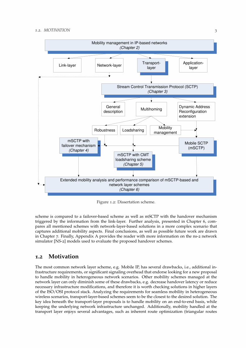
The structure of the dissertation is illustrated in Fig. 1.2. First, in Chapter 2, all basic definitionsand naming convention related to mobility management are given, followed by a detailed survey ofexisting mobility management solutions for IP-based networks. Presented review analyzes differentapproaches for mobility management in link, network, transport and application layer, accordingly.Chapter 3 provides the reader with the insights of the SCTP protocol, its new features, state-of-the-art, and relates that to the two most common transport layer protocols nowadays, namely TransportControl Protocol (TCP) [Postel, 1981] and User Datagram Protocol (UDP) [Postel, 1980]. One ofthe two new features of SCTP, multihoming, constitutes the essence of this dissertation in termsof extending its original scope of use, limited only to increasing protocol robustness, to handoverscenarios, as well as providing loadsharing at the transport-layer. Thanks to Dynamic Address Re-configuration (DAR) protocol extension described further in Chapter 3, SCTP multihoming can beapplied to mobility scenarios; such an upgraded configuration is called mSCTP. Consequences ofapplying mSCTP to handover scenarios are explained in the analysis provided in Section 3.3, whichaims to sketch the possible application scope for such a scheme. Next, in Chapter 4, a detaileddesign of a basic handover scheme based on mSCTP is specified. Failover mechanism providedoriginally to increase protocol’s robustness is reused to address handover triggering. Detailed eval-uation of such a failover-based scheme serves to establish a benchmark for more advanced solutionsproposed in this work. Chapter 5 suggests the idea of introducing the CMT loadsharing schemeinto mobility schemes based on mSCTP (mSCTP-CMT) in order to smooth the transition process,as well as increase the overall throughput of a proposed handover solution. The mSCTP-CMT
Cellular
phone
2,5 G
3G
WLAN
WLAN
WLAN
Hotspots
Satellite
WLANHotspots
Notebook
PDA
Figure 1.1: Heterogeneous RANs scenario.
1.2. MOTIVATION 3
Network-layerApplication-
layerLink-layer
Mobility management in IP-based networks
(Chapter 2)
General
descriptionMultihoming
Dynamic Address
Reconfigurationextension
Stream Control Transmission Protocol (SCTP)
(Chapter 3)
Robustness LoadsharingMobility
management
Extended mobility analysis and performance comparison of mSCTP-based and
network layer schemes
(Chapter 6)
mSCTP with
failover mechanism
(Chapter 4)mSCTP with CMT
loadsharing scheme
(Chapter 5)
Mobile SCTP
(mSCTP)
Transport-
layer
Figure 1.2: Dissertation scheme.
scheme is compared to a failover-based scheme as well as mSCTP with the handover mechanismtriggered by the information from the link-layer. Further analysis, presented in Chapter 6, com-pares all mentioned schemes with network-layer-based solutions in a more complex scenario thatcaptures additional mobility aspects. Final conclusions, as well as possible future work are drawnin Chapter 7. Finally, Appendix A provides the reader with more information on the ns-2 networksimulator [NS-2] models used to evaluate the proposed handover schemes.
1.2 Motivation
The most common network layer scheme, e.g. Mobile IP, has several drawbacks, i.e., additional in-frastructure requirements, or significant signaling overhead that endorse looking for a new proposalto handle mobility in heterogeneous network scenarios. Other mobility schemes managed at thenetwork layer can only diminish some of these drawbacks, e.g. decrease handover latency or reducenecessary infrastructure modifications, and therefore it is worth checking solutions in higher layersof the ISO/OSI protocol stack. Analyzing the requirements for seamless mobility in heterogeneouswireless scenarios, transport-layer-based schemes seem to be the closest to the desired solution. Thekey idea beneath the transport-layer proposals is to handle mobility on an end-to-end basis, whilekeeping the underlying network infrastructure unchanged. Additionally, mobility handled at thetransport layer enjoys several advantages, such as inherent route optimization (triangular routes
4 CHAPTER 1. INTRODUCTION
never occur), or the possibility of smooth handovers if the mobile node has multiple interfaces, tomention the most important characteristics. Author believes that this topic has still not been givenenough attention in the research community, and therefore proposes in this work to analyze one ofthe existing transport-layer mobility proposals in more details.
It is also essential to point out the main inconvenience of some of the transport-layer mobilityproposals is indirectly caused by the dominant role of well-established transport-layer protocols, likeTCP and UDP that share nearly all Internet traffic nowadays. Therefore, transport-layer schemes notderiving from TCP require significant modifications of pre-existing protocol stacks. Yet, there areseveral interesting proposals of new, innovative transport-layer protocols, brought recently by theInternet Engineering Task Force (IETF) Transport Area (TSVWG) working group [IETF TSVWG] thatstill lack broader application, and thus attract the attention of the research community. One of themis SCTP, which although originally not aimed to deal with transport layer mobility, can be seen as apromising alternative to face the requirements of mobility management in heterogeneous wirelessnetwork scenarios that TCP is not able to deal with. SCTP, being a fairly new protocol, has still tobecome better recognized and wider-spread transport protocol, and this particular application mayhelp to achieve that.
Last but not least, when introducing a new protocol, a relatively big effort should be spent notonly on its initial design and implementation, but also on making the proposal available for theresearch community to evaluate, and perform further development. SCTP has already made itsway to most of the systems stacks, traffic analyzers and simulation tools (e.g., ns-2 [SCTP-ns2] orQualnet [SCTP-Qualnet]), making itself widely-available for further evaluation. In this dissertation,the ns-2 simulator [NS-2] will be used as the main tool to conduct the performance analysis whenevaluating proposed SCTP-based mobility solutions.

Chapter 2
Mobility management
Mobility management is a fundamental piece of a B3G mobile data network architecture. In thiscontext, an open challenge is the design of solutions that can take full advantage of different IP-based technologies to support the desired mobility of multi-mode terminals, and at the same timeprovide the necessary Quality of Service (QoS) guarantees. The task becomes even more chal-lenging, taking into account the fact that the suite of TCP/IP protocols was proposed under theassumption that most of the devices are stationary, thus not particularly with the mobility aspectsin mind. So far numerous solutions addressing mobility in IP networks have been presented, butthe main question still remains open: what layer is the most appropriate for handling the mobility?
2.1 Definitions
Before going into details of the existing mobility solutions, there is a need to provide a set of basicdefinitions and mobility related terminology. Naming convention used in this dissertation followsthe IETF naming convention defined in [Manner and Kojo, 2004].
Administrative
domain #2Administrative
domain #1
Correspondent
Node
Access
Network #2
Access
Network #3
Mobile
Node Mobile
Node
Access
Network #1Access
NetworkGateway
AccessNetwork
GatewayNewAccess
Point /Access
Router
OldAccess
Router
Old
Access
Point
Access Point /Access Router
AccessNetwork
Gateway
Figure 2.1: Mobility scenario.

6 CHAPTER 2. MOBILITY MANAGEMENT
Basic terms. First, the following basic terms should be explained and clarified (Fig. 2.1):
- Point of attachment (PoA), the network side endpoint of a layer two link that includes a mobilenode as the other endpoint.
- Correspondent Node (CN), is an IP node with which a mobile node is communicating. It isassumed in this work that the CN is a fixed node, i.e., it is not changing its PoA and its IPaddress.
- Mobile node (MN), is an IP node capable of changing its PoA. A MN may have one or morewireless interfaces, and it either sends and receives packets (so called mobile host (MH)) orjust forwards the traffic as in case of mobile Router (MR). In this dissertation the term MNwill be used to denote a multi-mode wireless terminal, e.g., a cellular phone, PDA, notebook,etc., however its functionality it is just that of the MH.
- Access Point (AP), sometimes called base station (BS) or access point transceiver depending ontechnology, is a layer-two device offering wireless link connection to MNs.
- Access router (AR), refers to an IP router that reside on the edge of an access network offering IPconnectivity to MNs, and acting as default router for the MNs it is currently serving. Usually,each AR is connected to one or more APs. In case of WLAN networks it is common to finddevices with co-located AP and AR functionalities, referred to as wireless routers. In this work,for simplicity reasons in each of the access networks considered, an AP will be co-located withits corresponding AR.
- Old Access Router (OAR), is an AR that offered connectivity to the MN before a handover.
- New Access Router (NAR), is an AR that offers connectivity to the MN after a handover.
- Access Network Gateway (ANG), is a router that separates an access network from other IPnetworks. In a small AN, an ANG may also offer the services of an AR (be the same physicalnode).
- Access Network (AN), is an IP network which includes one or more access network routers(ANGs, ARs, and optionally other internal access network routers).
- Administrative Domain (AD), defines a collection of networks under the same administrativecontrol and grouped together for administrative purposes.
Mobility management principles. The current addressing scheme of the Internet is a consequenceof the design decisions made at the early days, when the Internet was merely just a static networkwith all the hosts connected through one specific interface. At the time that address-oriented approachwas developed some issues were considered invariant: (1) addresses were thought to be stationary(non-mobile), (2) an address received was the one sent (no tunneling mechanisms), (3) source anddestination were reversible, and (4) all hosts knew the address to which the packets should be sentto, to reach the wanted host. Since then, Internet underwent many revolutionary changes, with oneof the most important being the introduction of wireless interfaces. The need to support the increas-ing number of wireless hosts has led to a problem that the address-oriented architecture is unableto deal with, mobility. Changes proposed to accommodate mobility are pushing the Internet to ahost-oriented approach which separates the concept of the address and the unique device identifier.The addresses, being location-dependent, make the previously constant name-to-address bindingchange over time as the host address changes with the host mobility. Traditionally, the followingaspects of mobility can be distinguished:
• Terminal mobility is the ability of a MN to move between IP subnets within an AD or be-tween different ADs, while continuing to be reachable for incoming requests and maintainingsessions across subnet changes.
• Personal mobility describes the ability of addressing a user that can be located at several termi-nals.

2.1. DEFINITIONS 7
• Session mobility refers to maintaining (and transferring) a session when a user moves betweenterminals.
• Service mobility can be defined as the ability of users to maintain access to their services evenwhen moving and changing terminals or service providers.
Hereafter the main focus is put on terminal mobility, since it is the foundation of the analysisaddressed in this work, and consequently the word mobility used in this dissertation will referexclusively to terminal mobility. Management of terminal mobility includes two fundamental op-erations: location and handover management. According to Riegel and Tuexen [2007], handovermanagement deals with all the necessary operations to change a MN’s PoA to the IP network, whilemaintaining the communication with the CN. On the other hand, location management focuses onkeeping track of a MN’s current IP address, and providing this address to any entity needing tocommunicate with the MN, while being transparent to its peers. Additionally, mobility manage-ment poses several performance and deployment challenges. The most important performanceindicators are handover latency (time between the reception of the last packet in the old networkand arrival of the first packet in the new network), packet loss, signaling overhead and throughput.Meanwhile, the deployment requirements for mobility management focus on application trans-parency (minimum changes possible to the current applications and services), and simplicity ofintegration with the existing infrastructure (changes, if any, should be as simple as possible, andadding third-party devices should be avoided).
Terminal mobility of the MN can be addressed in different ways, depending on the scope,performance characteristics, control modes of handover techniques, etc. When classifying mobilityas a function of its scope, the following categories can be named [Giaretta, 2009]:
• Local mobility includes movements within an AN, e.g., intra-AN handover (change of the ARwithin the same AN), or just a change of the AR’s network interface to the MN affecting therouting path of the IP packets. Local mobility may also refer to a movement across differentsubnets belonging to the same AN.
• Global mobility covers movements across different ANs, or even ADs in various geographicalregions, as shown in Fig. 2.1.
Handover naming convention. Taxonomies provided so far in the literature present different ap-proaches for classifying various handover types, e.g., [Dutta et al., 2008]. Here, also a sampleclassification of different handover types is given that takes into account the following aspects (pro-vided list is orthogonal, so that each handover could be classified with one of the features in eachgroup):
- technology of the APs, between which the handover is made: either involving the same tech-nology (intra-technology or horizontal handover) or different technologies (inter-technology or ver-tical handover). The difference between horizontal and vertical handovers is not always clear,e.g., a handover from an 802.11b WLAN AP to a 802.11g WLAN AP can be interpreted eitherway.
- entity that makes the initial handover decision: mobile- and network-initiated handover.
- entity that has the primary control over the handover process: mobile- and network- controlledhandover.
- entity that provides information where to handover to: mobile-, network-assisted and unas-sisted handover.
- which of the ARs initiates the handover: either OAR or MN via OAR (push handover), orNAR or MN via NAR (pull handover).
- whether the handover is expected and some handover-related signaling can be done in ad-vance (planned or proactive handover) or not (unexpected or reactive handover).
- as a function of performance aspects handover can either aim at: minimizing packet lossesnot dealing with the additional delays in packet forwarding (smooth handover), minimizing
8 CHAPTER 2. MOBILITY MANAGEMENT
handover latency not dealing with losses (fast handover), not provoking change in service ca-pability, security, or quality (seamless handover).
2.2 Approaches to mobility management
Many proposals aspiring to solve the problem of terminal mobility management in heterogeneouswireless networks providing IP connectivity can be found in the literature. A good survey on thecurrent state of the art for mobility management in next-generation all-IP-based wireless systemscan be found in [Akyildiz et al., 2004]. Aiming at not repeating this work here, this dissertationwill examine the most important schemes in network, transport and application layer. Also a shortreference to the sub-network-layer solutions will be given.
2.2.1 Sub-network layer mobility issues
Handling terminal mobility below the network layer, which in IP networks provides globally usableaddresses, poses, especially in heterogeneous environments, several serious challenges that need tobe solved. The main limitation is introduced by the fact that the IP address can not be reconfiguredfrom the underlying link layer, and thus the scope of application of sub-network layer mobilitysolutions is limited to the same subnet, i.e., does not include a change of the IP address. Therefore,proposed solutions deal mainly with the dynamic update of the MAC switching tables. Neverthe-less, this type of solution can be applied to the heterogeneous networks, as long as the MN stayswithin the same subnet. Akyildiz et al. [2004] provide a detailed overview of link-layer mobilitysolutions in the current all-IP-based wireless systems. Due to the limited scalability, the discussedsolutions will not be addressed more in this work.
2.2.2 Network-layer schemes
Network layer, originally proposed to handle global addressing and routing, seems a natural can-didate to host the mobility management [Bhagwat et al., 1996]. Maintaining both functions andproviding support for mobility can be done twofold, either (1) routers will be required to use host-specific route information, updated as each host moves, or by (2) providing a hierarchical addressingstructure with its use limited to the domain of its definition, and extended by dedicated indirectionagents forwarding all traffic to a host staying beyond the given domain. The first approach can beeasily discarded due to the scalability problems, given the large number of Internet hosts nowadays,whilst the latter option stays feasible and aligned with the current Internet routing structure.
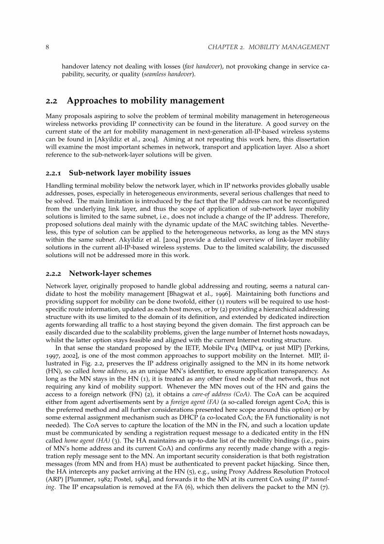
In that sense the standard proposed by the IETF, Mobile IPv4 (MIPv4, or just MIP) [Perkins,1997, 2002], is one of the most common approaches to support mobility on the Internet. MIP, il-lustrated in Fig. 2.2, preserves the IP address originally assigned to the MN in its home network(HN), so called home address, as an unique MN’s identifier, to ensure application transparency. Aslong as the MN stays in the HN (1), it is treated as any other fixed node of that network, thus notrequiring any kind of mobility support. Whenever the MN moves out of the HN and gains theaccess to a foreign network (FN) (2), it obtains a care-of address (CoA). The CoA can be acquiredeither from agent advertisements sent by a foreign agent (FA) (a so-called foreign agent CoA; this isthe preferred method and all further considerations presented here scope around this option) or bysome external assignment mechanism such as DHCP (a co-located CoA; the FA functionality is notneeded). The CoA serves to capture the location of the MN in the FN, and such a location updatemust be communicated by sending a registration request message to a dedicated entity in the HNcalled home agent (HA) (3). The HA maintains an up-to-date list of the mobility bindings (i.e., pairsof MN’s home address and its current CoA) and confirms any recently made change with a regis-tration reply message sent to the MN. An important security consideration is that both registrationmessages (from MN and from HA) must be authenticated to prevent packet hijacking. Since then,the HA intercepts any packet arriving at the HN (5), e.g., using Proxy Address Resolution Protocol(ARP) [Plummer, 1982; Postel, 1984], and forwards it to the MN at its current CoA using IP tunnel-ing. The IP encapsulation is removed at the FA (6), which then delivers the packet to the MN (7).

2.2. APPROACHES TO MOBILITY MANAGEMENT 9
Administrative
domain #2Administrative
domain #1
Correspondent
Node
HomeNetwork
Home
Agent
Foreign
Network
Foreign
Agent
(2)Mobile
Node Mobile
Node
(3)
(5)
(6)
(7)
(1)
(4)
Figure 2.2: Mobile IPv4 architecture and operations.
In the opposite direction, the MN can directly contact the CN (4), using its home address and theFA acting as the default router. This asymmetry is named the triangular routing. In case there areadditional security constraints posed by the FN, e.g., router’s ingress filtering, the packets from theMN to the CN must also be routed via the HA, using so-called reverse tunneling [Montenegro, 2001].
Triangular routing can be diminished with the route optimization extension (MIP-RO) [Johnsonand Perkins, 2001; Perkins and Johnson, 1998]. MIP-RO requires the MN to register its currentbinding at the CN. Then, the packets can be routed directly from the CN to the CoA, and thetriangular route via the HA is avoided. However, triangular routing is not the only of the MIP’sproblems, fully discussed by Perkins et al. [2007]. MIP registration process takes a long time,increasing therefore handover latency. While registering in the FN, the MN is not able to send orreceive packets until the registration at the HA is completed, what may induce a considerable packetloss. In addition, all agent advertisement and registration messages provoke a significant networkoverload. MIP scheme is usually classified as a global mobility scheme, and is tailored to followa MN’s movement across different subnets within an AD, or across different subnets belonging todifferent ADs. Yet, if the MN’s CoA is changed frequently, the MIP tunneling mechanism maylead to an unacceptable network overhead, especially in terms of signaling. To address these issues,several schemes have been proposed so far: Hawaii [Ramjee et al., 1999], Cellular IP (CIP) [Campbellet al., 1999], as well extensions to MIP: Hierarchical Mobile IP (HMIP) [Fogelstroem et al., 2007],Low-latency Mobile IP [El Malki, 2007], and Fast Handovers for Mobile IP (FMIP) [Koodli andPerkins, 2007], to mention the most important ones. Additionally, a detailed discussion of differentmobility protocols can be found in [Campbell et al., 2002].
Because of various limitations posed by IPv4, especially a limited 32-bit address space, the IETFhas proposed a new network layer protocol IPv6 [Deering and Hinden, 1998], to replace the IPv4.Mobility support in IPv6 is provided by Mobile IPv6 (MIPv6) [Johnson et al., 2004] that follows thebasic concepts of MIPv4. The main difference is the lack of the FA entity, as the MIPv6 protocol canoperate in any location without the support of local routers. Instead of IP encapsulation the IPv6headers are used to forward the packets to the MN that is away from its HN. Route optimizationis included as a part of the MIPv6 protocol [Nikander et al., 2005], not as a separate extension asin case of MIP-RO, and can coexist with routers that perform ingress filtering. To increase protocolrobustness the MIPv6 uses the IPv6 Neighbor Discovery Protocol (instead of ARP) what makes theMIPv6 solution independent of any particular link layer.
10 CHAPTER 2. MOBILITY MANAGEMENT
Administrative
domain #2Administrative
domain #1
Correspondent
Node
HomeNetwork
Home
Agent
Foreign
Network
(2)Mobile
Node Mobile
Node
(3)
(4)
(5)
(1)
Figure 2.3: Mobile IPv6 architecture and operations.
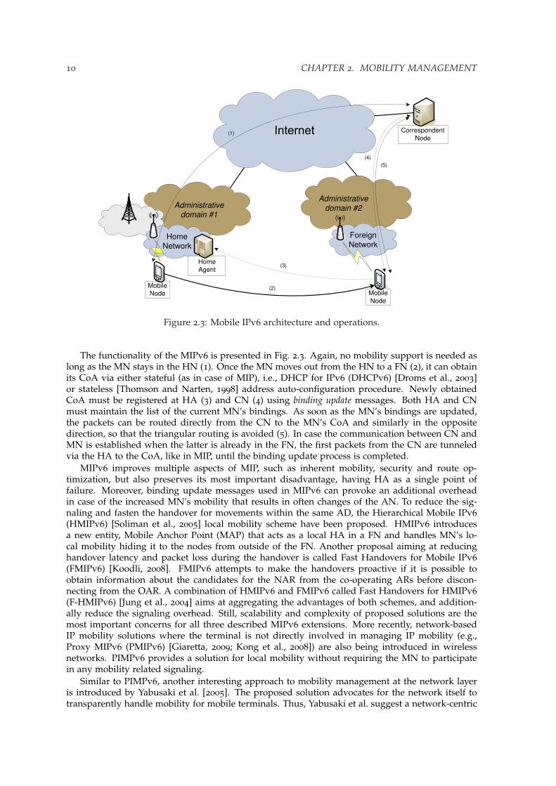
The functionality of the MIPv6 is presented in Fig. 2.3. Again, no mobility support is needed aslong as the MN stays in the HN (1). Once the MN moves out from the HN to a FN (2), it can obtainits CoA via either stateful (as in case of MIP), i.e., DHCP for IPv6 (DHCPv6) [Droms et al., 2003]or stateless [Thomson and Narten, 1998] address auto-configuration procedure. Newly obtainedCoA must be registered at HA (3) and CN (4) using binding update messages. Both HA and CNmust maintain the list of the current MN’s bindings. As soon as the MN’s bindings are updated,the packets can be routed directly from the CN to the MN’s CoA and similarly in the oppositedirection, so that the triangular routing is avoided (5). In case the communication between CN andMN is established when the latter is already in the FN, the first packets from the CN are tunneledvia the HA to the CoA, like in MIP, until the binding update process is completed.
MIPv6 improves multiple aspects of MIP, such as inherent mobility, security and route op-timization, but also preserves its most important disadvantage, having HA as a single point offailure. Moreover, binding update messages used in MIPv6 can provoke an additional overheadin case of the increased MN’s mobility that results in often changes of the AN. To reduce the sig-naling and fasten the handover for movements within the same AD, the Hierarchical Mobile IPv6(HMIPv6) [Soliman et al., 2005] local mobility scheme have been proposed. HMIPv6 introducesa new entity, Mobile Anchor Point (MAP) that acts as a local HA in a FN and handles MN’s lo-cal mobility hiding it to the nodes from outside of the FN. Another proposal aiming at reducinghandover latency and packet loss during the handover is called Fast Handovers for Mobile IPv6(FMIPv6) [Koodli, 2008]. FMIPv6 attempts to make the handovers proactive if it is possible toobtain information about the candidates for the NAR from the co-operating ARs before discon-necting from the OAR. A combination of HMIPv6 and FMIPv6 called Fast Handovers for HMIPv6(F-HMIPv6) [Jung et al., 2004] aims at aggregating the advantages of both schemes, and addition-ally reduce the signaling overhead. Still, scalability and complexity of proposed solutions are themost important concerns for all three described MIPv6 extensions. More recently, network-basedIP mobility solutions where the terminal is not directly involved in managing IP mobility (e.g.,Proxy MIPv6 (PMIPv6) [Giaretta, 2009; Kong et al., 2008]) are also being introduced in wirelessnetworks. PIMPv6 provides a solution for local mobility without requiring the MN to participatein any mobility related signaling.
Similar to PIMPv6, another interesting approach to mobility management at the network layeris introduced by Yabusaki et al. [2005]. The proposed solution advocates for the network itself totransparently handle mobility for mobile terminals. Thus, Yabusaki et al. suggest a network-centric

2.2. APPROACHES TO MOBILITY MANAGEMENT 11
solution to handle IP mobility in analogy with conventional 2G/3G networks, where mobility man-agement has mainly been implemented as network intelligence, a concept just opposite to the end-to-end intelligence architectural principle of the Internet [Bush and Meyer, 2002; Carpenter, 1996].In this approach, IP addresses are used separately as host addresses and routing addresses. Thus,a host address is semi-permanently assigned to a MN and a routing address is temporarily assignedto the MN when datagrams are delivered to it. Datagrams are sent from a CN to a MN with thehost address of the MN but then, within the IP mobile network, datagrams are transported usingthe routing address generated from the host address. All in all, user terminals are unaware of thisrerouting management that is handled entirely in the network.
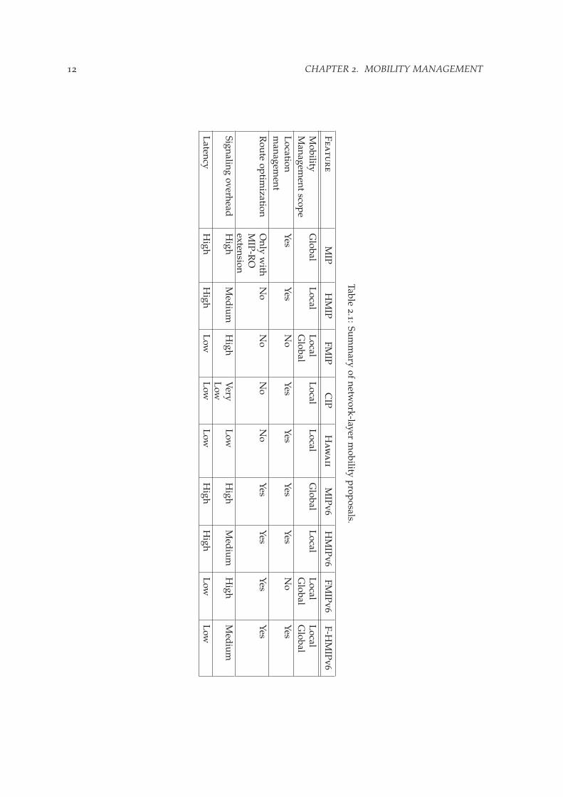
For more information and proposals for handling mobility at the network layer readers can referto [Campbell et al., 2002; Saha et al., 2004], here Table 2.1 summarizes the most important aspects ofthe discussed network layer schemes. Values specified for latency and signaling overhead providea relative comparison among discussed schemes.
2.2.3 Transport-layer schemes
Unlike network-layer schemes such as MIP, which make mobility transparent to upper layers byincreasing the burden and responsibility of the Internet infrastructure, transport-layer schemes arebased on an end-to-end approach to mobility that attempts to keep the Internet infrastructure un-changed by allowing the end-hosts to take care of mobility. This approach is gaining an increasingattention in the recent years, also because transport-layer-based schemes enjoy several advantagessuch as inherent route optimization (triangular routes never occur), no dependence on the conceptof HN or additional infrastructure beyond DHCP and Domain Name System (DNS) [Mockapetris,1987], and more precisely Dynamic DNS (DDNS) [Vixie et al., 1997], as well as either the possibilityof smooth handovers if the MN has multiple interfaces, or the ability to pause transmission dur-ing mobility-induced temporary disconnections [Eddy, 2004]. It is also essential to point out thatthe main inconvenience is caused by the dominant role of well-established transport-layer proto-cols, like TCP and UDP, which were not targeted for the wireless scenarios. Consequently, mostof the proposed transport-layer schemes focuses on improving the performance of the TCP in thewireless networks and providing TCP support for the mobility. In contrast, proposals based onthe new innovative transport-layer protocols, like SCTP or Datagram Congestion Control Protocol(DCCP) [Kohler et al., 2006], require significant modifications of the current protocol stacks.
According to Riegel and Tuexen [2007], transport-layer mobility is handled by the transport layersof the connection endpoints so that it is transparent to application-layer protocols not using IPaddresses in their messages. A mobility-enabled transport protocol supports an IP-address change onthe underlying network layer, while keeping the end-to-end connection alive. E.g., a possible wayto achieve that is as follows: the MN first obtains a new IP address, then tells the CN (using theestablished transport-layer connection) that it is now reachable by the new IP address, and thenhandover can be performed. So far, several proposals to handle mobility at the transport layerhave been developed. A complete survey and classification of mobility management schemes atthe transport layer can be found in [Atiquzzaman and Reaz, 2005]. In particular, the mentionedclassification distinguishes between:
• Connection-migration protocols, provide a migration scheme for the connection, once the new IPaddress acquired, and before the old IP address is retained. Connection-migration schemesinvolve also a notification to the CN about the change. Most typically, during the migrationprocess the connection is stopped or put under wait for the time the migration is performed,in order to reduce packet loss in the presence of long and frequent disconnections through-out the handover process. An example of connection-migration protocol is Freeze-TCP [Goffet al., 2000] that enters the persist mode, on the perceived disconnection or handover event,indicated by a MN with zero window advertisements (ZWAs). Once in the persistent opera-tion the CN sends zero window probes (ZWPs) to check the availability of the MN, and onthe reception of a positive response immediately starts sending data.
• Gateway-based mobility schemes, as, e.g., the Mobile Socket Service (MSOCKS) scheme [Maltzand Bhagwat, 1998], introduce a dedicated gateway in the network for handling the mobility.Gateway splits the connection between the CN and the MN, allowing the latter to change its
12 CHAPTER 2. MOBILITY MANAGEMENT
Table2.1:Sum
mary
ofnetw
ork-layerm
obilityproposals.
Feature
MIP
HM
IPFM
IPC
IPH
awa
iiM
IPv6H
MIPv6
FMIPv6
F-HM
IPv6
Mobility
Managem
entscope
Global
LocalLocalG
lobalLocal
LocalG
lobalLocal
LocalG
lobalLocalG
lobalLocationm
anagement
YesYes
No
YesYes
YesYes
No
Yes
Route
optimization
Only
with
MIP-R
Oextension
No
No
No
No
YesYes
YesYes
Signalingoverhead
High
Medium
High
VeryLow
LowH
ighM
ediumH
ighM
edium
LatencyH
ighH
ighLow
LowLow
High
High
LowLow

2.2. APPROACHES TO MOBILITY MANAGEMENT 13
Administrative
domain #2
Access
Network #2
(6)
(4)
Administrative
domain #1
Correspondent
Node
Access
Network #1
(2)
Mobile
Node
(1)
Mobile
Node
(3)
(7)
(8)
Mobile
Node
(5)
Mobile
Node
Figure 2.4: mSCTP architecture and operations.
connection with the gateway when performing the handover. These solutions, however, donot deal with location management, bring in a single point of failure and may decrease faulttolerance.
• Handover protocols, address only handover management issues, without considering locationmanagement. Protocols such as mSCTP or Mobile Multimedia Streaming Protocol (MMSP) [Mat-suoka et al., 2003] usually offer a soft-handover solution, and aim at reducing handover-induced packet loss, providing scalability and fault tolerance.
• Complete-mobility schemes, also called mobility managers, like Migrate [Snoeren and Balakrish-nan, 2000] and Seamless IP diversity-based Generalized Mobility Architecture (SIGMA) [Fuet al., 2005], include both handover and location management. Both solutions use DNS forlocation-management purposes, supporting either hard (Migrate) or soft handover (SIGMA).Such protocols only require modifications at the transport layer, thus leaving the existingnetwork infrastructure unchanged.
Fig. 2.4 illustrates the basic operation of a handover process handled by mSCTP, as an exampleof transport-layer mobility scheme. When establishing an mSCTP association between MN and CN,both nodes exchange first the lists of the IP addresses valid for the communication (1). Only oneof the source-destination pairs is selected to send the data to (a so-called primary path), whereasall remaining pairs serve only for backup purposes. As long as the MN stays in the area wherethe initially defined IP addresses are available there are no mobility-related concerns. If the MNmoves to an area where a new IP address (an address that was not included in the initial list)can be obtained from a network (2), as soon as the new IP address becomes available it has tobe communicated to the CN using specific control messages (address configuration chunks) (3).The security concern here is that the address manipulation creates an opportunity for hijackingattacks. To prevent hijacking attacks mSCTP specification recommends using IPsec or TransportLayer Security (TLS) [Stewart, Tuexen, and Camarillo, 2007]. Once the new IP address has beenadded to the association, the MN may decide whether still use the old IP address to send the datato, or in an appropriate moment (e.g., basing its decision on the signal measurement informationobtained from the link-layer) (4) switch the primary path to the new IP address (5). After theaddress change, the transmission can continue uninterrupted on the new IP address (a smooth oreven seamless handover). Leaving the old AN (6) the unnecessary IP address(es) can be removed(7), as further transmission goes on (8). Still, an open issue of the presented mobility scheme is lack

14 CHAPTER 2. MOBILITY MANAGEMENT
Administrative
domain #2Administrative
domain #1
Correspondent
Node
Foreign
Network #1
Foreign
Network #2
(6)
Mobile
Node
(5)
Mobile
Node
(3)
(8) (11)
Home
Network
SIP
Server
(1)
(4)
(2)
(9)(10)
(7)
Figure 2.5: SIP architecture and operations.
of any support for the location management. As the location management can not be handled at theend hosts, a possible solution is either to reuse the MIP, as shown in [Koh and Xie, 2004; Noonanet al., 2002] or to use the DDNS.
2.2.4 Application-layer schemes
Handling mobility at the application layer has also received a lot of attention, since a solution that isalmost independent of the underlying wireless or wired access technologies and network-layer ele-ments can be envisaged. In this context, the most important proposal is Session Initiation Protocol(SIP) [Rosenberg et al., 2002] that although initially developed by the IETF as an application multi-media signaling protocol, can be also used for mobility management [Kim et al., 2004; Schulzrinneand Wedlund, 2000; Shacham et al., 2007; Wedlund and Schulzrinne, 1999]. SIP architecture intro-duces the following entities: user agent (UA), proxy server (PS), redirect server (RS) and registrarserver (RGS). The UA identifies SIP messages coming from the user, and tracks SIP messages follow-ing the user actions, acting as both client and server. The PS relays SIP messages, the RS receives SIPmessages and identifies the current location of the MN, whereas the RGS accepts register requestsfrom the UA who has logged onto the network, and then places that information into the locationservice. The PS, RS and RGS functions are usually placed together in one entity called SIP Server(SS).
Fig. 2.5 explains the details of a mobility management scheme based on SIP. Firstly, a MN regis-ters to the SS to provide reachability information. In order to initiate a SIP session with the MN, theCN consults the current MN’s location with the SS (1,2) and then sends a session invitation messageto the MN (3). Then, the regular SIP procedure to establish the session follows (4), refer [Rosenberget al., 2002] for details. Once the session is established the data can be sent (5). When a MN duringan active session moves into a different network (6), it first receives a new network address viaDHCP, and then sends a new session invitation to the CN (7) with an updated session descriptioncontaining the same call-id (session identifier) and the new IP address. After receiving new ses-sion invitation at the CN, subsequent data packets are forwarded to the MN (8) using either thisnew address (in case the underlying protocol is UDP), or using IP encapsulation (for SIP sessionsover TCP) [Vakil et al., 2001]. Then, the MN updates its location information at the SS by sendinga register message (9, 10), so the session can be correctly redirected (11). SIP mobility scheme is

2.3. CONCLUSIONS 15
Table 2.2: Comparison of different mobility management approaches.
Feature Network layer Transport layer Application layer
Location managementsupport
Included Requires externallocation manager
Included
Route optimization Binding updatenecessary
Not required Not provided
Network support Required Not required Not requiredSeamless transition Transport layer
must deal withlosses andpath changes
Included Not included
Security Included Included IncludedRequired infrastruc-ture changes
– hosts– specializedrouters (HA, FA)
– hosts – hosts– SIP servers
characterized by significant handover latency, due to signaling, and overhead caused by the IP en-capsulation. Moreover, SIP by itself does not guarantee the maintenance of established TCP sessionsor UDP port bindings when moving, so further extensions such as S-SIP [Zhang et al., 2007] areneeded to provide seamless handover capabilities.
2.3 Conclusions
The most important approaches for handling mobility management presented in this chapter aresummarized in Table 2.2. As discussed in some detail here, it has been noted that currently there isnot a single mobility solution approach able to cover in a satisfactory manner all possible mobilitymanagement aspects. Network layer solutions require significant modifications to the existing in-frastructure (providing single points of failure with the specialized routers they introduce, despiteof the numerous efforts to introduce robustness in this matter, e.g., back-up HA, multihoming inMIP [Huang et al., 2008], etc.), as well as considerable support from the network (significant signal-ing overhead). In contrast, transport layer solutions do not provide location management serviceand to do so, are dependent on other layers protocols, such as DDNS or MIP. Meanwhile, appli-cation layer proposals are aiming at specific type of applications, e.g. SIP for real-time traffic andmultimedia, and in this sense seem quite limited. All presented mobility management schemes candeal to some extent with the security issues, however not all the proposals have developed theirsecurity considerations with enough detail, e.g., the use of IPsec to prevent hijacking attacks withmSCTP has been recommended without specifying a detailed procedure.
A comprehensive discussion on the pros and cons of handling mobility management at differentstack layers can be also found in [Eddy, 2004]. Eddy concludes that transport-layer mobility schemesbest fit the requirements of today’s IP-based services, and that there should be more inter-layercommunication to avoid conflicts and inefficiencies. Following this conclusion this work will scopeon the transport layer mobility, and in particular on mSCTP, as an example of a mobility-enabledtransport protocol, and also because of its new, interesting feature, multihoming.

16 CHAPTER 2. MOBILITY MANAGEMENT

Chapter 3
SCTP for transport-layer mobility
The Stream Control Transmission Protocol (SCTP) was first announced in October 2000 in the, nowan obsolete, RFC 2960 [Stewart et al., 2000]. Publication of the RFC 2960 concluded over two-yearlong IETF Signaling Transport (SIGTRAN) working group [IETF SIGTRAN] project on a new reli-able protocol for transporting packet-based Public Switched Telephone Network (PSTN) signalingover IP networks. However, all began even before SIGTRAN group was formed late in 1998. A (pro-tocol) proposal, called Multi-network Datagram Transmission Protocol (MDTP) [Stewart and Xie,1998], developed independently from the IETF to overcome TCP weaknesses, had been submitted tothe IETF editors in August 1998. Few months later when SIGTRAN group formed, MDTP was theonly working implementation that met most of the requirements for its future-projected CommonTransport Protocol (CTP), described in [Ong et al., 1999]. Namely, solution to head-of-line (HoL)blocking problem, multihoming feature and performance comparable to TCP made the MDTP atop pick for the CTP first draft. In nearly two years from that point CTP underwent many deeprevisions, and so did the protocol name (CTP, CSTP, SCTP), before finally evolving to the SCTP inits RFC 2960 shape.
Already at the specification stage authors envisaged that SCTP capabilities would let extend itsscope of use to a general transport protocol1. Indeed, the following years saw a growing rangeof possible applications of SCTP in many works discussing both signaling, and more general pur-poses [Coene, 2002; Stewart et al., 2004]. From 2001, the maintenance of the protocol has beentracked by the IETF Transport Area (TSVWG) working group [IETF TSVWG]. Since then, the origi-nal (RFC 2960) protocol specification was slightly modified (checksum change [Stone et al., 2002]),and updated with suggested implementer’s fixes (specification errata and issues [Stewart et al.,2006]). Both updates are included in the current protocol specification RFC 4960 [Stewart, 2007],released in September 2007 that will be further referred in this work as standard SCTP.
3.1 SCTP overview
Standard SCTP provides a reliable, full-duplex connection with flow and congestion control al-gorithms that are derived from TCP, thus following the same Additive-Increase Multiplicative-Decrease (AIMD) behavior. An SCTP connection is called association, and is established usinga four-way handshake (instead of a three-way handshake as in TCP) in order to improve proto-col security and make it resistant to blind denial of service (DoS) attacks (such as flooding andmasquerade). SCTP offers message abstraction to the application, in contrast to the byte streamabstraction provided by TCP, in order to better suit the communication pattern of signaling ap-plications. What made SCTP a subject of considerable interest however, are two new features itintroduces: multihoming and multistreaming.
1Originally SCTP was developed as signaling telephony transport protocol and that was reflected in the first MDTP drafts.However, already in fourth MDTP draft dating to April 1999, this limitation was removed from the specification.

18 CHAPTER 3. SCTP FOR TRANSPORT-LAYER MOBILITY
0 8 16 24 32
Verification Tag
Checksum (CRC32c)
Common
header
Chunk #1
Chunk #2
...
Chunk #last
Chunks
Source Port Number Destination Port Number
Figure 3.1: SCTP PDU structure.
0 8 16 24 32
Chunk
value
Chunk-type-specific Mandatory Fields
Optional/Variable Length Parameters or Error Causes
Parameter Value
8 16 24 320
Chunk Type Chunk Flags Chunk Length
Parameter Type Parameter Length
Figure 3.2: Chunk details.
3.1.1 Protocol basics
The SCTP protocol data unit (SCTP-PDU), also called simply SCTP packet, consist of a SCTP commonheader, and one or more chunks, as shown in Fig. 3.1 [Stewart, 2007]. SCTP common header contains:16-bit source and destination port number fields (to identify the association which this SCTP-PDUbelongs to and demultiplex it to the correct receiving application, respectively), 32-bit verificationtag field (that serves to validate the sender), and a 32-bit checksum field (the CRC32c checksumvalue is calculated for the entire SCTP-PDU, with all zeros in the checksum field). A chunk carrieseither control or user data, and has Type-Length-Value (TLV) structure as shown in Fig. 3.2 [Stewart,2007]. Chunk includes a 8-bit chunk type field that identifies the chunk type (refer Table 3.1 for afull list of currently defined chunk types, extending the standard list given in [Stewart, 2007]; thechunk ids are specified in a way that the highest bit defines SCTP-PDU processing action and thesecond highest bit handles error reporting on an unrecognized chunk type), a 8-bit chunk flagfield (chunk-specific sets, if not specified all the bits are set to zeros), a 16-bit chunk length field

3.1. SCTP OVERVIEW 19
Table 3.1: List of chunk types (if not stated otherwise, chunks are defined within the standardSCTP).
ID Value Chunk type
0x00 Payload data (DATA)0x01 Initiation (INIT)0x02 Initiation Acknowledgment (INIT ACK)0x03 Selective Acknowledgment (SACK)0x04 Heartbeat Request (HB)0x05 Heartbeat Acknowledgment (HB ACK)0x06 Abort (ABORT)0x07 Shutdown (SHUTDOWN)0x08 Shutdown Acknowledgment (SHUTDOWN ACK)0x09 Operation Error (ERROR)0x0A State Cookie (COOKIE)0x0B Cookie Acknowledgment (COOKIE ACK)0x0C reserved for Explicit Congestion Notification (ECNE)0x0D reserved for Congestion Window Reduced (CWR)0x0E Shutdown Complete (SHUTDOWN COMPLETE)0x0F Authentication (AUTH) a
0x10 DDP Segment Chunk (DDP-SC) b
0x11 DDP Stream Session Control (DDP-SSC) b
0x80 Address Configuration Acknowledgment (ASCONF ACK) c
0x84 Padding (PADDING) d
0xC0 Forward Transmission Sequence Number (FORWARD TSN) e
0xC1 Address Configuration Change (ASCONF) c
0x3F, 0x7F0xBF, 0xFF
reserved for IETF-defined chunk extensions
rest future chunk definitionsa covered by authentication specification [Tuexen et al., 2007].b defined with Direct Data Placement (DDP)c added by the DAR extension [Stewart et al., 2007].d provided with the padding chunk specificatione added by the PR-SCTP extension [Stewart et al., 2004].
(count in Bytes, without chunk padding), and chunk value field of a variable length that carries thechunk-specific transfered information within mandatory and optional parameter fields (the latteralso have the TLV format). The length of a chunk must be a multiple of 4 Bytes, and is paddedwith zeros to do so if necessary (no more than 3 Bytes of padding is added at the sender). All thechunks but INIT, INIT ACK and SHUTDOWN can be bundled into one SCTP-PDU, unless the sizeof Maximum Transmission Unit (MTU) is not exceeded.
Standard SCTP is a connection-oriented protocol working on the top of the connection-less net-work. The term association is used to name the relationship between two SCTP endpoints, distin-guishing it from a TCP connection as a more complex structure that can span over multiple IPaddresses at each endpoint. An SCTP association is set up in a four-way handshake as shown inFig. 3.3 [Stewart, 2007]. This is one of the major differences to the TCP, which with its three-wayhandshake is prone to blind DoS attacks such as SYN flooding. To prevent that SCTP introduces socalled cookie mechanism that adds the additional leg to the association setup. Another differenceto the TCP can be seen during the release of the association, which is simpler in SCTP, and involves

20 CHAPTER 3. SCTP FOR TRANSPORT-LAYER MOBILITY
(a)
ClosedCookie
Wait
[ASSOCIATE]
create TCB
send INIT
start init timer
received INIT ACK
send COOKIE ECHO
stop init timer
start cookie timer
EstablishedCookie
Echoed
received COOKIE ACK
stop cookie timer
received valid COOKIE ECHO
create TRANSMISSION
CONTROL BLOCK (TCB)
send COOKIE ACK
received INIT
generate cookie
send INIT ACK
Any
state
[ABORT]
send ABORT
delete TCB
or
received ABORT
delete TCB
Diagram explanation
SCTP user primitive call
SCTP control chunks
timer events
[ABORT]
COOKIE ECHO
start init timer
init timer expires
try up to
Max.Init.Retransmits times
retransmit INIT
restart init timer
If fails send ABORT
cookie timer expires
try up to
Max.Init.Retransmits times
retransmit COOKIE ECHO
restart cookie timer
If fails send ABORT
(b)
Figure 3.3: SCTP association setup: (a) chunk flow; and, (b) finite state machine.
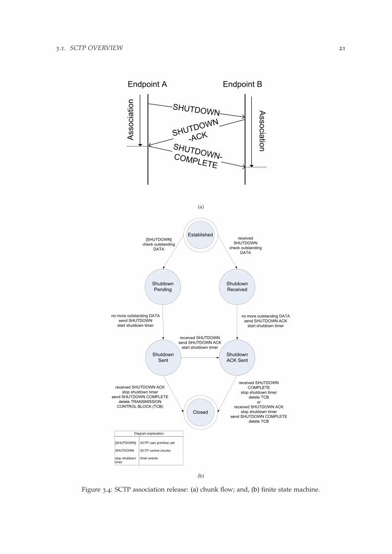
3.1. SCTP OVERVIEW 21
(a)
Established
Shutdown
Received
Shutdown
ACK Sent
received SHUTDOWN ACK
stop shutdown timer
send SHUTDOWN COMPLETE
delete TRANSMISSION
CONTROL BLOCK (TCB)
no more outstanding DATA
send SHUTDOWN
start shutdown timer
[SHUTDOWN]
check outstanding
DATA
Shutdown
Pending
Closed
Shutdown
Sent
received
SHUTDOWN
check outstanding
DATA
no more outstanding DATA
send SHUTDOWN ACK
start shutdown timer
received SHUTDOWN
send SHUTDOWN ACK
start shutdown timer
received SHUTDOWN
COMPLETE
stop shutdown timer
delete TCB
or
received SHUTDOWN ACK
stop shutdown timer
send SHUTDOWN COMPLETE
delete TCB
Diagram explanation
SCTP user primitive call
SCTP control chunks
timer events
[SHUTDOWN]
SHUTDOWN
stop shutdown
timer
(b)
Figure 3.4: SCTP association release: (a) chunk flow; and, (b) finite state machine.
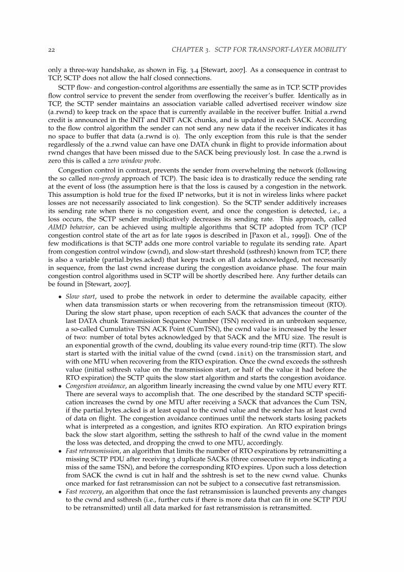
22 CHAPTER 3. SCTP FOR TRANSPORT-LAYER MOBILITY
only a three-way handshake, as shown in Fig. 3.4 [Stewart, 2007]. As a consequence in contrast toTCP, SCTP does not allow the half closed connections.
SCTP flow- and congestion-control algorithms are essentially the same as in TCP. SCTP providesflow control service to prevent the sender from overflowing the receiver’s buffer. Identically as inTCP, the SCTP sender maintains an association variable called advertised receiver window size(a rwnd) to keep track on the space that is currently available in the receiver buffer. Initial a rwndcredit is announced in the INIT and INIT ACK chunks, and is updated in each SACK. Accordingto the flow control algorithm the sender can not send any new data if the receiver indicates it hasno space to buffer that data (a rwnd is 0). The only exception from this rule is that the senderregardlessly of the a rwnd value can have one DATA chunk in flight to provide information aboutrwnd changes that have been missed due to the SACK being previously lost. In case the a rwnd iszero this is called a zero window probe.
Congestion control in contrast, prevents the sender from overwhelming the network (followingthe so called non-greedy approach of TCP). The basic idea is to drastically reduce the sending rateat the event of loss (the assumption here is that the loss is caused by a congestion in the network.This assumption is hold true for the fixed IP networks, but it is not in wireless links where packetlosses are not necessarily associated to link congestion). So the SCTP sender additively increasesits sending rate when there is no congestion event, and once the congestion is detected, i.e., aloss occurs, the SCTP sender multiplicatively decreases its sending rate. This approach, calledAIMD behavior, can be achieved using multiple algorithms that SCTP adopted from TCP (TCPcongestion control state of the art as for late 1990s is described in [Paxon et al., 1999]). One of thefew modifications is that SCTP adds one more control variable to regulate its sending rate. Apartfrom congestion control window (cwnd), and slow-start threshold (ssthresh) known from TCP, thereis also a variable (partial bytes acked) that keeps track on all data acknowledged, not necessarilyin sequence, from the last cwnd increase during the congestion avoidance phase. The four maincongestion control algorithms used in SCTP will be shortly described here. Any further details canbe found in [Stewart, 2007].
• Slow start, used to probe the network in order to determine the available capacity, eitherwhen data transmission starts or when recovering from the retransmission timeout (RTO).During the slow start phase, upon reception of each SACK that advances the counter of thelast DATA chunk Transmission Sequence Number (TSN) received in an unbroken sequence,a so-called Cumulative TSN ACK Point (CumTSN), the cwnd value is increased by the lesserof two: number of total bytes acknowledged by that SACK and the MTU size. The result isan exponential growth of the cwnd, doubling its value every round-trip time (RTT). The slowstart is started with the initial value of the cwnd (cwnd.init) on the transmission start, andwith one MTU when recovering from the RTO expiration. Once the cwnd exceeds the ssthreshvalue (initial ssthresh value on the transmission start, or half of the value it had before theRTO expiration) the SCTP quits the slow start algorithm and starts the congestion avoidance.
• Congestion avoidance, an algorithm linearly increasing the cwnd value by one MTU every RTT.There are several ways to accomplish that. The one described by the standard SCTP specifi-cation increases the cwnd by one MTU after receiving a SACK that advances the Cum TSN,if the partial bytes acked is at least equal to the cwnd value and the sender has at least cwndof data on flight. The congestion avoidance continues until the network starts losing packetswhat is interpreted as a congestion, and ignites RTO expiration. An RTO expiration bringsback the slow start algorithm, setting the ssthresh to half of the cwnd value in the momentthe loss was detected, and dropping the cnwd to one MTU, accordingly.
• Fast retransmission, an algorithm that limits the number of RTO expirations by retransmitting amissing SCTP PDU after receiving 3 duplicate SACKs (three consecutive reports indicating amiss of the same TSN), and before the corresponding RTO expires. Upon such a loss detectionfrom SACK the cwnd is cut in half and the sshtresh is set to the new cwnd value. Chunksonce marked for fast retransmission can not be subject to a consecutive fast retransmission.
• Fast recovery, an algorithm that once the fast retransmission is launched prevents any changesto the cwnd and ssthresh (i.e., further cuts if there is more data that can fit in one SCTP PDUto be retransmitted) until all data marked for fast retransmission is retransmitted.

3.1. SCTP OVERVIEW 23
InternetInternet
Host A
Host B
Interface 1Interface 1
Interface 2
Interface 2
Access
Network #3
Access
Network #4
Access
Network #1
Access
Network #2
Figure 3.5: SCTP multihoming.
3.1.2 New protocol features
One of the new features provided by the standard SCTP is transport-layer multihoming. Multihoming(Fig. 3.5) binds multiple source-destination IP addresses for a single association between two SCTPendpoints. These IP addresses are exchanged and verified during the association setup, and eachdestination transport address is considered as a different path towards the corresponding endpoint.An important remark regarding the path concept in the SCTP must be made here. SCTP specifica-tion [Stewart, 2007] defines the path as: the route taken by the SCTP packets sent by one SCTP endpoint toa specific destination transport address of its peer SCTP endpoint. This definition is a consensus achievedat the early stage of the protocol specification development [Stewart et al., 2000], and was specif-ically not changed since then. The main argument in favor of the current path definition is thatsource based routing is not widely deployed over the Internet, so the SCTP implementation doesnot need to control the source address on which packets are sent to a given destination. One couldargue that in case there are multiple local interfaces and multiple remote addresses, the number ofpossible paths should be simply a combination of all possible source-destination IP address pairs.Such an approach would be more robust in case of failures affecting both endpoints (if an alter-native path through an intermediate router exists), and also would provide additional benefits forloadsharing applications. Nevertheless, at this stage there are several procedures that are handledas per destination address2, e.g., path verification, that would have to be adjusted to such a modifiedpath definition. Also the necessary changes would have to affect congestion control as well as errorcounting in its current shape.
During the association setup, one of the available paths is selected as the primary path, used fortransporting all new data chunks during normal data transmission, whereas all remaining paths,called alternate paths, serve only for retransmissions. Alternate paths are often referred in theliterature as backup paths, especially in the robustness context of multihoming. Multihoming, inthe case of IP networks, means multiple IP addresses, and typically (but not necessarily) impliesmultiple link-layer interfaces.
Multihoming was originally designed for environments requiring high application availabilityand reliability, such as the delivery of Signaling System No. 7 (SS7) messages. Despite the evolutionof SCTP towards a general transport protocol, this design principle has been kept. Consequently, thescope of use for multihoming defined within RFC 4960 [Stewart, 2007] is only for handling singleretransmissions and performing primary path failover in case of a permanent link failure. Anyother applications, e.g., transport-layer handover or loadsharing over multiple network paths, arenot supported within the standard SCTP specification, and instead should be covered by dedicatedprotocol extensions. Regardless of this limitation, SCTP multihoming seems a promising protocolfeature that may easily be leveraged to provide support for both mentioned applications.
When considering the use of multihoming in transport-layer handover context, it is very im-portant to keep in mind that standard SCTP has no mechanisms to allow dynamic changes to theset of IP addresses specified for an active association (at the association setup). Thus, in a mobilenetwork scenario, if an association has already been established for a given IP address and a new
2Note however that the path supervision process (DATA and corresponding SACK chunks) is handled per source-destination IP address pair

24 CHAPTER 3. SCTP FOR TRANSPORT-LAYER MOBILITY
Host A
Sendqueues
Receivequeues
Sendqueues
Receivequeues
Stream
Stream
Stream
Stream
Host B
Figure 3.6: SCTP multistreaming.
PoA with a different IP address becomes available, there is no way to include it in the associationand switch the primary path over to the new network connection. An extension to standard SCTPthat facilitates dynamic address manipulation, and hence enables handover support using SCTPmultihoming is described in Section 3.1.3. Another important consideration about handover appli-cation of multihoming is that with standard SCTP only a single path is used for data transmission(i.e., the primary path) while all other available paths can handle retransmissions only. Then, thedecision of changing the primary path relies mainly on the failover mechanism, what is inspectedin more detail in Chapter 4.
The biggest challenge for loadsharing application of multihoming is that simultaneous datatransfer over multiple paths can provoke packet reordering at the receiver, what would deteriorateSCTP performance, since congestion control algorithms in standard SCTP are derived from TCP,and hence do not work well when reordering is common [Iyengar et al., 2006]. Thus, to accomplishloadsharing the SCTP send-buffer management and congestion control must be updated to takeinto account the problems of sending data over multiple paths using a single sequence-numberspace, and the consequences of sender-introduced reordering. So far, there is no commonly definedextension that facilitates loadsharing for SCTP, existing proposals are analyzed in Chapter 5.
Multistreaming, illustrated on Fig. 3.6, is the second of the newly introduced SCTP features.Multistreaming allows the establishment of associations with multiple streams. Streams are uni-directional data flows within a single association. The number of requested streams is declaredduring the association setup and the streams are valid during the entire association lifetime. Eachstream is distinguished with the Stream Identifier field included in each chunk, so that chunksfrom different streams can be bundled inside one SCTP PDU. To preserve order within a stream theStream Sequence Number (SSN) is used. Consequently, TCP’s HoL blocking problem stalling en-tire TCP connection is reduced to the affected SCTP stream only, as data received in order within astream (handled by SSN) but not within the entire association (counted using TSN) can be deliveredto the application. Among the most important applications of multistreaming are priority streamscheduling, preferential treatment, and reducing the latency of streaming multimedia in high-lossenvironments. Last but not least, multistreaming, jointly with the partially reliable extension toSCTP (PR-SCTP) [Stewart et al., 2004] can be used to support real-time applications.
3.1.3 Protocol extensions
The Dynamic Address Reconfiguration (DAR) SCTP extension [Stewart et al., 2007], although origi-nally defined to help with IPv6 renumbering and hot-pluggable cards by the IETF SIGTRAN work-ing group [IETF SIGTRAN], can be easily leveraged to make SCTP a mobility-enabled transportprotocol. It should be emphasized that this extension is seen as a mobility enabling feature, but notas a mobility solution by itself [Koh and Xie, 2005]. The DAR extension allows SCTP to dynamicallyadd or delete IP addresses, and request the primary-path change during an active SCTP association,by means of two new chunk types: ASCONF and ASCONF-ACK (check the Table 3.1), and six newparameters: Add IP Address, Delete IP Address, Set Primary Address, Error Cause Indication, Success Indi-cation, Adaptation Layer Indication. Modifying the IP address(es) of the association increases the riskof association hijacking [Stewart, Tuexen, and Camarillo, 2007] and therefore the ASCONF chunk

3.2. SCTP STATE OF THE ART IN RESEARCH 25
must be sent in an authenticated way (an AUTH chunk is bundled before the ASCONF chunk), asdescribed in [Tuexen et al., 2007]. Standard SCTP enhanced with the DAR extension is also referredto as mobile SCTP (mSCTP) [Koh and Xie, 2005; Riegel and Tuexen, 2007].
With mSCTP, the IP address(es) may be announced to the endpoints during association initial-ization and changed whenever it is needed during the association lifetime. When adding (deleting)an IP address to (from) an association, the new address is not considered fully added (deleted) untilthe ASCONF-ACK message is received. An addition or deletion of an IP address may be combinedwith changing of the primary path. However, only addresses already belonging to the associationcan be set as the primary, otherwise the Set Primary Address request is discarded. Before anyDATA can be sent to the newly added destination, the new destination must undergo a path ver-ification procedure. The path verification procedure is done by means of HB chunk that may bepiggybacked on the ASCONF-ACK response to a new destination. Once the HB-ACK response isreceived from the remote peer, the destination is considered as confirmed and available for normaldata transfer. mSCTP preserves the same congestion control rules as standard SCTP, and logically,a lot of research performed recently on SCTP could be useful for mSCTP development.
Another extension to standard SCTP, PR-SCTP, offering a non-duplicate, in-order data deliveryservice with controlled loss (standard SCTP provides all these with no-loss data delivery), will notbe discussed here, as it is not directly related to the subject of the dissertation. Readers interestedin more detail should refer to RFC 3758 [Stewart et al., 2004].
3.1.4 Summary
The array of the features offered by SCTP that were discussed through Section 3.1 is summarizedin Table 3.2, first provided in [Stewart and Amer, 2007]. An interesting comparison relates SCTPcapabilities to two transport-layer workhorses of the current TCP/IP stack: TCP and UDP, raisingthe question whether SCTP can be a viable substitute to any of these protocols.
3.2 SCTP state of the art in research
In order to complement presented protocol overview and resume many emerging ideas that havebeen brought so far in the literature, the SCTP-related research will be revised here by the means ofspecially dedicated taxonomy, first proposed in [Budzisz et al., 2008]. Before proceeding with thetaxonomy results, it must be stated that especially the new protocol features have attracted attentionof the researchers from diverse fields, being one of the main reasons for creating this classification.
3.2.1 Taxonomy
The purpose of a taxonomy is, in general terms, to provide a classification into an ordered system.How the system should be constructed is an open question and must be tailored to each specificinstance. Ideally, the categorization should be complete and non-overlapping. The taxonomy pro-posed by Budzisz et al. [2008] for SCTP is constructed using four orthogonal dimensions with anumber of non-overlapping categories in each dimension, as shown in Fig. 3.7. Every single clas-sified object, namely a research article related to SCTP, can be projected to one or more categorieswithin each dimension.
The main design goal and, unsurprisingly, the hardest problem to tackle at the early stage ofdefining the classification categories, was to minimize the possible overlap between them, in orderto reduce as much as possible the ambiguity of what category some research aspect may relate to.As classification work progressed, the initial set of proposed categories was refined (merge/split op-erations) to create a final taxonomy that has a high degree of orthogonality and is versatile enoughto evaluate practically all SCTP-related research. This iterative mode of taxonomy development alsoresulted in a reduced complexity for the final taxonomy that will be now presented in detail.

26 CHAPTER 3. SCTP FOR TRANSPORT-LAYER MOBILITY
Table 3.2: Comparison of transport-layer protocols
Service / Feature SCTP TCP UDP
Connection-oriented Yes Yes NoHalf-closed connections No Yes N/aProtection againstblind DoS attacks
Yes No N/a
Dynamic addressmanipulation
Optional a No N/a
Reliable data transfer Yes Yes NoPartial-reliabledata transfer
Optional b No No
Preservation of applicationmessage boundaries
Yes No Yes
Application PDUfragmentation/bundling
Yes Yes No
Ordered data delivery Yes c Yes NoUnordered data delivery Yes No YesFull-duplexdata transmission
Yes Yes Yes
Flow and congestion control Yes Yes NoSelective acknowledgments Yes Optional NoPath max. transmissionunit discovery
Yes Yes No
Explicit congestion notificationsupport
Yes Yes No
Multistreaming Yes No NoMultihoming Yes No No
a covered with DAR extension.b covered with PR-SCTP extension.c the data within a stream is delivered in order.
Dimension 1: Protocol feature examined
The first dimension used in this taxonomy classifies the research into different categories definedupon the protocol feature or functionality examined. As pointed out in Section 3.1, compared toTCP, SCTP provides new, interesting functionality. Much of SCTP research obviously targets thisnew functionality and examines it from different viewpoints. Besides that, SCTP has a number offeatures, identical or similar to TCP, that have spurred some research too. In case of multihom-ing, the feature that attracts almost half of the classified articles, it was considered appropriate todistinguish three separate subcategories, depending on the aim in which this feature is used. Thecategories in dimension 1 are the following:
1. Multihoming. The multihoming feature was originally designed for enhancing end-to-endrobustness by using transport layer failover to an alternate path when the primary path fails.Later research has explored other uses of multihoming, and to classify all these uses threesubcategories are introduced:
(a) MH-Robust. This is the original use considered for multihoming, the end-to-end ro-bustness by using failover to the alternate path.
(b) MH-Handover. The multihoming functionality of SCTP can also be used as a buildingblock to provide transport layer mobility management solutions.
(c) MH-Loadsharing. The multihoming feature may be used to concurrently transfer dataover multiple paths in a load-balancing fashion. This creates both a potential for im-
3.2. SCTP STATE OF THE ART IN RESEARCH 27
Dim 1
Dim 2
Dim
3
C26 C29
C1
3
C21 ... ...
C11
...
...
...
C34
C35
...
Dim 4
C41
C42
...
C31
Figure 3.7: Graphical illustration of proposed taxonomy.
proved end-to-end performance and a number of complicating issues that need to beaddressed.
2. DAR. The extension to SCTP for a dynamic address manipulation during an active SCTPassociation is an essential building block for handling mobility at the transport layer foreither single-, or multi-homed nodes.
3. Multistreaming. The capability of SCTP that allows a single association to have multiplelogically separate streams. This functionality is new relative to TCP and one major advantageis that it can reduce the HoL blocking which can occur with TCP since there is no orderingrequirement between the streams.
4. PR-SCTP. The partially reliable extension to SCTP offers more flexibility with regards to thereliability of the transport service. The ability to provide partial reliability opens up newpossibilities in how to handle the reliability-versus-latency trade-offs at various layers in theprotocol stack.
5. SH-Congestion. Congestion control is a central issue for any transport protocol that is to bedeployed on the Internet. SCTP’s congestion control for single-homed associations is to someextent similar to TCP’s, but also has some differences. There is an abundance of literature onTCP congestion control, and the impact of SCTP’s congestion control nuances on wired andwireless networks is clearly a relevant topic.
6. Security. SCTP provides some new security enhancements, and the multihoming capabili-ties of SCTP may potentially lead to an increased confidentiality since multihoming allowssplitting data over separate physical paths.

28 CHAPTER 3. SCTP FOR TRANSPORT-LAYER MOBILITY
7. Survey. This specific category captures all publication that provide a general protocol overview,rather than an analysis of a particular protocol feature.
8. Other. Some additional and diverse aspects of SCTP that are not covered by any of the abovecategories (checksum usage, . . . ) are classified here.
Dimension 2: Application area
This dimension focuses on the application area that the research to be classified relates to. The ap-plication area influences both the traffic data pattern (more precisely, the transfer size distributionas well as the data generation process, i.e., if data is always available or not, and also the consump-tion rate for streaming) and the required performance targets. The categories in dimension 2 arethe following:
1. Signaling. Since SCTP was originally designed for transporting SS7 signaling, the perfor-mance in this application domain is important. SCTP can also be used to transfer other kindsof signaling traffic such as SIP.
2. Multimedia. SCTP, and especially together with the PR-SCTP extension that provides partialreliability, can be used to transfer multimedia data. The multistreaming capabilities of SCTPmaps very well to multimedia traffic having multiple media streams. This application areahas its own set of challenges and is therefore handled in a separate category.
3. Web. Web transfer is a large application area for TCP, and may be so also for SCTP. SCTP’smultistreaming ability is one of the factors that may impact the transport layer performanceof SCTP in this application area.
4. Bulk. Applications such as File Transfer Protocol (FTP) are commonly used when examiningtransport layer protocols, and these are also relevant for SCTP. Examination of single-homedSCTP for bulk transfer provides insights into the steady-state protocol performance and al-lows comparison to similar TCP results. Bulk traffic is characterized by being large enoughto have the transfer time decided by the steady-state behavior and to be greedy, i.e., alwayshave data to send if there are resources available to transmit it.
5. MPI. The Message Passing Interface (MPI) application area covers the use of SCTP in localand wide area cluster and grid environments. MPI is nowadays the dominant model usedin high-performance computing, and SCTP can be seen as a promising option of IP-basedtransport support for MPI.
6. Other-applications. This category groups few other specified (but diverse) applications,not captured by any of the above categories, such as for example Data Acquisition Systems(DAQ).
7. Unspecified. This category is used when no application area has been defined in the classi-fied research, e.g., when the research focus on conceptual discussions of some aspect.
Dimension 3: Network environment
This dimension covers the network environment that is considered in the research to be classi-fied. This dimension is divided into two domains (wireless/wired) with several categories. Thecategories in dimension 3 are the following:
Wireless domain1. WLAN. The WLAN environment is characterized by relatively high bandwidth and a reliable
link layer that to a large extent shields the upper layers from physical layer problems suchas bit-errors and frame losses, but can show significant end-to-end delay variation. WhenWLANs are used in a MANET setting the research article falls under the next category.
2. MANET/VANET. The Mobile Ad-hoc Network (MANET) environment has a number ofdefining characteristics, such as relatively low bandwidth, large variation in end-to-end de-lays and losses directly caused by congestion or temporary route unavailability. This categoryalso includes vehicular networks (VANET), since they are similar in nature and there are toofew articles in the latter group to form a separate category.

3.2. SCTP STATE OF THE ART IN RESEARCH 29
3. Cellular. This category, which spans from GSM to 3G high speed packet access (e.g., 3GPPHSDPA), offers medium to low bandwidths and considerable variation in end-to-end delays.In these types of networks, a reliable link layer can ensure that there will be no wirelesslosses, but only congestion losses.
4. Heterogeneous. This category refers to the case where coexisting heterogeneous wirelessnetworks are considered in the research, e.g., vertical handover scenarios.
5. Space. Space (also referred as satellite) networks typically have long round-trip times whichaffects the transport layer behavior.
There are also cases where the wireless environments used are not sufficiently detailed to be placedin one of the above categories:
6) Wireless-General. This category catches research where a wireless environment is used tomotivate the existence of, e.g., bit-errors, but no further description of any specific technologyis provided.
7) Wireless-Unspecified. This category reflects the case where wireless environment is notexplicitly defined in the publication, but it can be inferred from other information that awireless setting is present. This is specially the case for some research concerning handover.
Wired domain8) Managed. This category captures network environments where a high degree of control
exists over the network for the entire end-to-end path. This allows appropriate dimension-ing, traffic engineering and QoS mechanisms to provide the desired network characteristics.Operator-owned IP-based signaling networks are a typical example of managed networks,and an original design target for SCTP.
9) QoS. This network environment refers to cases where some Quality of Service (QoS) enhanc-ing mechanisms are employed, which leads to the possibility of providing a better servicethan pure best effort.
10) Best effort. The best effort network environment provides only best effort end-to-end packettransfer service (e.g., best effort Internet) without any assumptions about, or restrictions on,delay bounds, loss rates, etc.
Dimension 4: Study approach
The fourth dimension considers the method used to obtain the results. Different approaches havedifferent benefits and drawbacks, and the results are strengthened, if multiple approaches are used.The following are the categories:
1. Conceptual. The conceptual description approach describes and reasons about ideas, mech-anisms and functionalities in a general way without providing quantitative data to analyzethe performance.
2. Analytical. The analytical modeling tries to describe the essential behavior of an entity (suchas a protocol) with a mathematical expression that given some input parameters providessome metric of interest. When a suitable expression has been derived, it can then easilybe used to predict the performance of the entity under a range of conditions. However, inorder to create a tractable formula the expression must often be simplified which introducesinaccuracies and highlights the need for model verification.
3. Simulation. The simulation approach also uses abstract representations of the entity understudy, but in this case the abstractions are much more detailed and can include all relevantprotocol functionality. Also with simulations, there is a need to verify that the abstractionused in the simulation is correct and representative. Simulation allows a large parameterspace to be explored and can provide considerable detail in the output.
4. Emulation. In contrast to analytical modeling and simulation, the emulation approach usesactual protocol implementations running on a real hardware. The emulation approach nat-urally captures the behavior of a protocol implementation, and also allows for factors such aspossible interaction effects with the operating system, device drivers and communicationshardware. Here, it is the behavior of the end-to-end connectivity that is abstracted to somedegree by the employed emulator.

30 CHAPTER 3. SCTP FOR TRANSPORT-LAYER MOBILITY
5. Live. The live network approach entails performing experiments on a running communica-tions network. This naturally includes all aspects, both at the endpoints and at the networklevel. However, live experiments are hard to control and repeat. Getting access to live net-works to the extent necessary may also be problematic in some instances.
3.2.2 SCTP research analysis
Classification methodology
In the presented study only works that could have had a considerable audience in research com-munity are included, to be precise, journal or conference articles that were publicly available, andwritten in English (some research work in other languages was also identified but not included inoverall results, as possibly not having that big impact on the research community). The informationabout research works was collected having in mind general availability as a principal rule. As asource of information the most common databases were taken into account, and in particular:
• The IEEE Xplore database [IEEEXplore],• The ACM Digital Library [ACM],• The BibFinder database [BibFinder],• The Engineering Village database [EngVillage],• CiteSeer.IST [CiteSeer],• GoogleTMScholar [Google Scholar],• The ISI Web of Knowledge [ISI].
Once the information about the articles was collected, the articles underwent a detailed classificationprocess, to allocate them in the appropriate category within each dimension. In case the articlecovers more than one category within a dimension, the article is counted equally in each of thecategories that reflect the contents of the given article (i.e., the article is considered to fit or not eachspecific category without any kind of weights for articles that fall into multiple categories). Theentire classification is available on-line [SCTP Survey].
An important consideration is also the time frame for the collected research. RFC 2960 markedthe initial year when the SCTP research took off (i.e., year 2000), whereas on the other end, to securethe trustworthy metrics, the end of 2007 was set up as the cut-off date. It should be noted that thenumbers for the articles published in 2007 is less reliable, since there can be quite some lag betweenpaper publication and the time it appears in the examined databases. Fig. 3.8 shows the percentagedistribution of all years analyzed. Out of 279 total articles collected, merely 22% were published inthe first four years since the protocol specification was announced in 2000. The largest number ofarticles so far (66) has been published in 2006, however the differences between any of the last fouryears are relatively small. Year 2007 brings the ambiguity to the interpretation of the most recenttrend. Yet it is not clear, whether the SCTP research enters a steady state fluctuating around 50articles per year, or there is still not enough data available from the year 2007 to reflect a steadygrowth.
SCTP research profile
As mentioned in Section 3.2.1, an article can be projected to more than one category within eachdimension. To quantify the extent of this multiple assignment we define α, as a ratio of the numberof all category assignments to the total number of articles published, calculated for each dimension.Thus, α is influenced by both versatility of the analyzed research and the difficulty of creating anon-overlapping classification. This is especially true for dimension 1 which has the highest valueof α (1.34).
Fig. 3.9 presents an overview of the investigated research within each of the taxonomy dimen-sions. Dimension 1, protocol feature examined (Fig. 3.9a), clearly shows the domination of twomajor new SCTP features in SCTP-related research. Multihoming alone stands for 46% of all hitswithin the dimension, and adding multistreaming brings it up already to more than 59% of allhits. The DAR extension provides also a considerable contribution (nearly 15% of all hits). How-ever, most of the articles treats DAR in conjunction with the multihoming feature (MH-Handover

3.2. SCTP STATE OF THE ART IN RESEARCH 31
< 1%3%
6%
12%
20%
16%
24%
18%
Total number of published articles per year
200020012002
2003
2004
2005
2006
2007
Figure 3.8: Annual distribution of all published articles.
category). Out of the remaining protocol features, the most explored is single-homed congestion,a topic that has already been well studied for the SCTP ancestor TCP. Relatively little attention inthe research community has been spent on security issues and the PR-SCTP extension, both fallingbelow 5% of all hits.
Dimension 2, application area (Fig. 3.9b), in contrast is rather highly polarized. With a verylow α (1.03), almost all articles had been assigned to only one category. Most of the research,nearly 50% of all hits and articles in this case, use the bulk transfer application model. Almost onethird of all these articles classified as bulk transfer does not have any explicit specification aboutthe application model that was used, but had implicit indications to the bulk model. The originalapplication area of SCTP, signaling transport yields slightly more than 17% of all articles. The samenumber of articles have an unspecified application model, a quite common case especially withinthe research devoted to transport-layer mobility. The multimedia category, reaching almost 15%,seems a promising research direction for SCTP. The combined total for the rest of the categories isless than 5%, with web transfer and MPI being the biggest contributors.
Dimension 3, network environment (Fig. 3.9c), has again a very low α (1.03), and a quite clearclassification. Wireless related research provides slightly more than a half of all classified articles(about 53%). In contrast the biggest single category belongs to the wired domain, best effort countsfor about one third of all the research. The remaining two wired categories have some contributiontoo, but both below 10%. Heterogeneous networks (18%) are the most commonly analyzed wirelessnetwork environment, again mostly because of the transport-layer handover research. Also generalwireless environments catch a considerable number of articles (14%), most of them being conceptualmodels, or general handover schemes without having any particular network clearly specified.WLAN and MANET/VANET networks have attracted less attention so far, slightly over 5% each.
Dimension 4, study approach (Fig. 3.9d) with α = 1.14, counts for some articles having morethan one category assigned, i.e., combining two different study approaches. This is especially thecase for the analytical models being verified by either simulations or emulations. More than ahalf of all SCTP related research has been conducted using simulations, either the ns-2 simulationmodel [SCTP-ns2] or Qualnet [SCTP-Qualnet], both delivered by University of Delaware. Emula-tions contribute to about 20% of the articles. Conceptual descriptions and analytical models come

32 CHAPTER 3. SCTP FOR TRANSPORT-LAYER MOBILITY
0%
5%
10%
15%
20%
25%
DIM1 category
Per
cent
age
of to
tal n
umbe
r of
art
icle
s w
ithin
eac
h D
IM1
cate
gory
MH−ROBUST
MH−HANDOVER
MH−LOADSHARINGDAR
MULTISTREAMING
PR−SCTP
SH−CONGESTION
SECURITY
SURVEYOTHER
α = 1.34
(a)
0%
5%
10%
15%
20%
25%
30%
35%
40%
45%
50%
DIM2 category
Per
cent
age
of to
tal n
umbe
r of
art
icle
s w
ithin
eac
h D
IM2
cate
gory
SIGNALING
MULTIMEDIAWEB
BULK MPI
OTHER−APP.
UNSPECIFIED
α = 1.03
(b)
Figure 3.9: Number of articles within each category for: (a) Dimension 1: Protocol feature examined;(b) Dimension 2: Application area. Wondering why the total is greater than 100%? Documents withmultiple categories within a dimension may be counted multiple times.

3.2. SCTP STATE OF THE ART IN RESEARCH 33
0%
5%
10%
15%
20%
25%
30%
DIM3 category
Per
cent
age
of to
tal n
umbe
r of
art
icle
s w
ithin
eac
h D
IM3
cate
gory
WLAN
MANET/VANET
CELLULAR
HETEROGENEOUSSPACE
WIRELESS−GEN
WIRELESS−UNSP
MANAGEDQOS
BEST−EFF
α = 1.03
(c)
0%
10%
20%
30%
40%
50%
DIM4 category
Per
cent
age
of to
tal n
umbe
r of
art
icle
s w
ithin
eac
h D
IM4
cate
gory
CONCEPTUAL
ANALYTICAL
SIMULATION
EMULATIONLIVE
α = 1.14
(d)
Figure 3.9: Number of articles within each category for: (c) Dimension 3: Network environment;and, (d) Dimension 4: Study approach. Wondering why the total is greater than 100%? Documentswith multiple categories within a dimension may be counted multiple times.

34 CHAPTER 3. SCTP FOR TRANSPORT-LAYER MOBILITY
close behind, both combined contribute for nearly 30% of all articles, leaving the remaining 3% forlive experiments.
Category annual distribution
Fig. 3.10 illustrates the annual distribution of the classified research. The graphics presented for eachdimension reflect the contribution of each category for the annual mark, as well as total number ofarticles published each year, providing a graphical interpretation of the α ratio, previously definedin Section 3.2.2.
In Dimension 1 (Fig. 3.10a), its two leaders contribute to the overall score in a different wayover time. The MH-Robust category presents quite stable annual contributions almost from thefirst year after the protocol specification was released. This initial focus on robustness issues wasexpected having in mind that this was the original use of the multihoming feature. In contrast,the MH-Handover category represents a new trend in SCTP research, started in the end of 2003.From this moment (over the last five years) an incrementing annual contribution of MH-Handoverarticles can be observed. More detailed analysis of the handover-related work can be found in Sec-tion 3.3.1. A similar trend can be seen for the third application of multihoming, the loadsharing,discussed here in Chapter 5. MH-Loadsharing hardly starts in 2003, 2004 being the first year with aconsiderable contribution and a steady growth until now. As mentioned before in Section 3.2.2, theDAR extension is strongly related to the MH-Handover feature and therefore follows its character-istic. Multistreaming, the second novel feature of SCTP, similarly to MH-Robust provides a stablecontribution over all inspected years. In contrast, two of the analyzed categories face a decreasingtrend recently. Single-homed congestion, after providing a considerable bulk of research in the firstfew years, seemed to lose researchers’ interest in 2007. The same happened to survey articles, onceSCTP became fairly known protocol (about 2005) this type of publications appear less frequently.
Dimension 2 (Fig. 3.10b) is a quite clear cut with stable contributions from the bulk traffic thatdominates this dimension all the years from the beginning. Signaling and multimedia applicationsalso show stable trends over the analyzed years. Sensitivity of the remaining categories firmly pre-vents to draw the exact tendencies, since with relatively little research done, already one articlemakes a significant difference. E.g., web applications over SCTP and SCTP use for MPI applica-tions were both first announced in 2003, however a stable contribution in each case dates back to2005. Experiments with other applications of SCTP appeared in last two of the analyzed years,nevertheless a single paper a year can not be seen as a stable trend.
The dimension 3 time evolution (Fig. 3.10c) is also dominated by one main player, in this casethe best-effort category. The main wireless category, heterogeneous networks, dates back to 2003.However, observing its evolution, it can be said that it is one of the driving forces of the SCTPresearch nowadays. In contrast, a considerable research devoted to satellite environments in theinitial years, ended up in 2003. Then, the topic came back again in 2005, but with a considerablylower attention. Another tendency that can be observed is that the wireless research in recent yearsis less general, the articles become more specific to a particular network solution. Looking at theshares between the wired and wireless fields, we observe the wired domination before year 2003.Now the tendency over the last two years is slightly favorable for wireless networks.
Dimension 4 (Fig. 3.10d) observes a domination of the simulation approach since the publicationof the protocol model for the ns-2 simulator in 2002 [SCTP-ns2]. The emulation approach providesless contributions, however dates back to the beginning when the protocol was just introduced. Overthe years there is a stable contribution of conceptual and analytical approaches (with peaks datingback to 2004 and 2006, respectively). The novelty is the increase in the number of live experimentsover the last two years.
3.3 Mobility implications
As argued in Section 2.2.3, there are important advantages in handling handover at the transportlayer. mSCTP can be seen as a viable candidate for providing transport-layer mobility that, unlikea pure network-layer scheme, has the potential to perform smooth handovers, if the mobile node

3.3. MOBILITY IMPLICATIONS 35
2000 2001 2002 2003 2004 2005 2006 20070
10
20
30
40
50
60
70
80
90
Year
Num
ber
of a
rtic
les
Total number of articles within each DIM1 category per year
MH−ROBUSTMH−HANDOVERMH−LOADSHARINGDARMULTISTREAMINGPR−SCTPSH−CONGESTIONSECURITYSURVEYOTHERNum. of articles published
(a)
2000 2001 2002 2003 2004 2005 2006 20070
10
20
30
40
50
60
70
Year
Num
ber
of a
rtic
les
Total number of articles within each DIM2 category per year
SIGNALINGMULTIMEDIAWEBBULKMPIOTHER−APP.UNSPECIFIEDNum. of articles published
(b)
Figure 3.10: Annual distribution of all articles within each dimension: (a) Dimension 1: Protocolfeature examined; (b) Dimension 2: Application area.

36 CHAPTER 3. SCTP FOR TRANSPORT-LAYER MOBILITY
2000 2001 2002 2003 2004 2005 2006 20070
10
20
30
40
50
60
70
Year
Num
ber
of a
rtic
les
Total number of articles within each DIM3 category per year
WLANMANET/VANETCELLULARHETEROGENEOUSSPACEWIRELESS−GENWIRELESS−UNSPMANAGEDQOSBEST−EFFNum. of articles published
(c)
2000 2001 2002 2003 2004 2005 2006 20070
10
20
30
40
50
60
70
80
90
Year
Num
ber
of a
rtic
les
Total number of articles within each DIM4 category per year
CONCEPTUALANALYTICALSIMULATIONEMULATIONLIVENum. of articles published
(d)
Figure 3.10: Annual distribution of all articles within each dimension: (c) Dimension 3: Networkenvironment; and, (d) Dimension 4: Study approach.
3.3. MOBILITY IMPLICATIONS 37
(MN) is multihomed. Moreover, mobility handled by the transport layer is fully transparent toapplication-layer protocols that do not include end-host IP addresses in their application data. Nev-ertheless, despite the importance of the aforementioned advantages, it is vital and highly relevantto identify under which situations/conditions such potential can be really exploited. Therefore,this section will first provide an overview of the related work on transport-layer handover basedon mSCTP, and then discuss the applicability of mSCTP in a set of practical heterogeneous radioaccess networks scenarios, firstly presented in [Budzisz et al., 2008]. In particular, the identificationof mSCTP’s applicability scenarios is based on the consideration of aspects such as the numberof network interfaces on the MN, the number of IP addresses configured for the CN, and the IPaddress change during the handover process. For each scenario, expected benefits and open issuesof the application of mSCTP are also stressed. It is worth to remark here that, even though thediscussion focuses on mSCTP, most conclusions drawn here can be extended to any transport-layerhandover solution.
3.3.1 Related work
Using SCTP multihoming only for robustness-related purposes has been seen as not taking the fulladvantage of what this feature can relatively offer. This idea had been discussed already duringRFC 2960 specification, however due to time constraints other applications of multihoming werenot included into the final document. This status quo has been maintained in the current SCTPspecification, nevertheless at this point the considerable benefits of alternative uses of multihomingare rather evident, and are reflected in the analyzed research. Yet the specification stays unchanged,and any non-standard applications of multihoming should be subject to a separate protocol exten-sion. Indeed, this is the case with transport layer mobility. The idea of using the multihomingfeature to provide mobility support surged as soon as the work on the DAR extension specificationgot to an advanced stage. Paradoxically, the original scope of use of the DAR extension, as men-tioned in Section 3.1.3, for IPv6 renumbering and hot-pluggable cards, has never gained attentionthat can be compared to that of handover-related research. Thus, both protocol features, DAR andmultihoming, are usually put together when handover support is discussed. The are only a fewexceptions to this rule, e.g., mobility support for single-homed nodes based on the DAR featureonly, as described in [Honda et al., 2007]. Mobility for a single-homed nodes is analyzed in scenarioB in Section 3.3.2.
mSCTP as a candidate for providing transport-layer mobility has still several open points thatboosted the research classified as MH-Handover in the taxonomy presented in Section 3.2.1. Apartfrom articles that introduce the mSCTP-based handover concept, and these that compare the mSCTPproposal to other handover schemes (mainly MIP and SIP), there are several subgroups of articlesthat relate to mSCTP’s main open points: proposals for appropriate handover strategies, supportfrom lower layers to the handover scheme, and enhancements introduced during the handoverprocess.
Fig 3.11 illustrates the distribution of handover-related research over the remaining dimensionsof the taxonomy. First thing to notice is that there is a small variation regarding applications con-sidered in the analyzed literature. If the application is explicitly specified, usually it is bulk transfer.Signaling or multimedia applications are less frequent and more specific solutions influencing thedesign of the proposed handover scheme, e.g., Voice over IP (VoIP) in the work by Fitzpatricket al. [2006]. In contrast, among the network scenarios analyzed there is much more diversity, withalmost every wireless category being represented in the scatter plot. The most typical handoverscenarios include heterogeneous networks, and wireless general or wireless unspecified categoryin case of conceptual works. mSCTP-based handover schemes are also evaluated in homogeneousnetworks, mainly in WLAN, and considerably less often in cellular networks. Future trends inhandover-related research may also consider MANET environments that so far has had only a fewcontributions. Unsurprisingly, the vast majority of the research dedicated to transport layer mobil-ity uses the ns-2 SCTP model to evaluate the proposed ideas. Only a few works go beyond thisscheme and provide results from emulated environments, most of them using the Linux kernelimplementation [SCTP-LK].
Research on transport-layer mobility based on mSCTP dates back to late 2003. Most of the
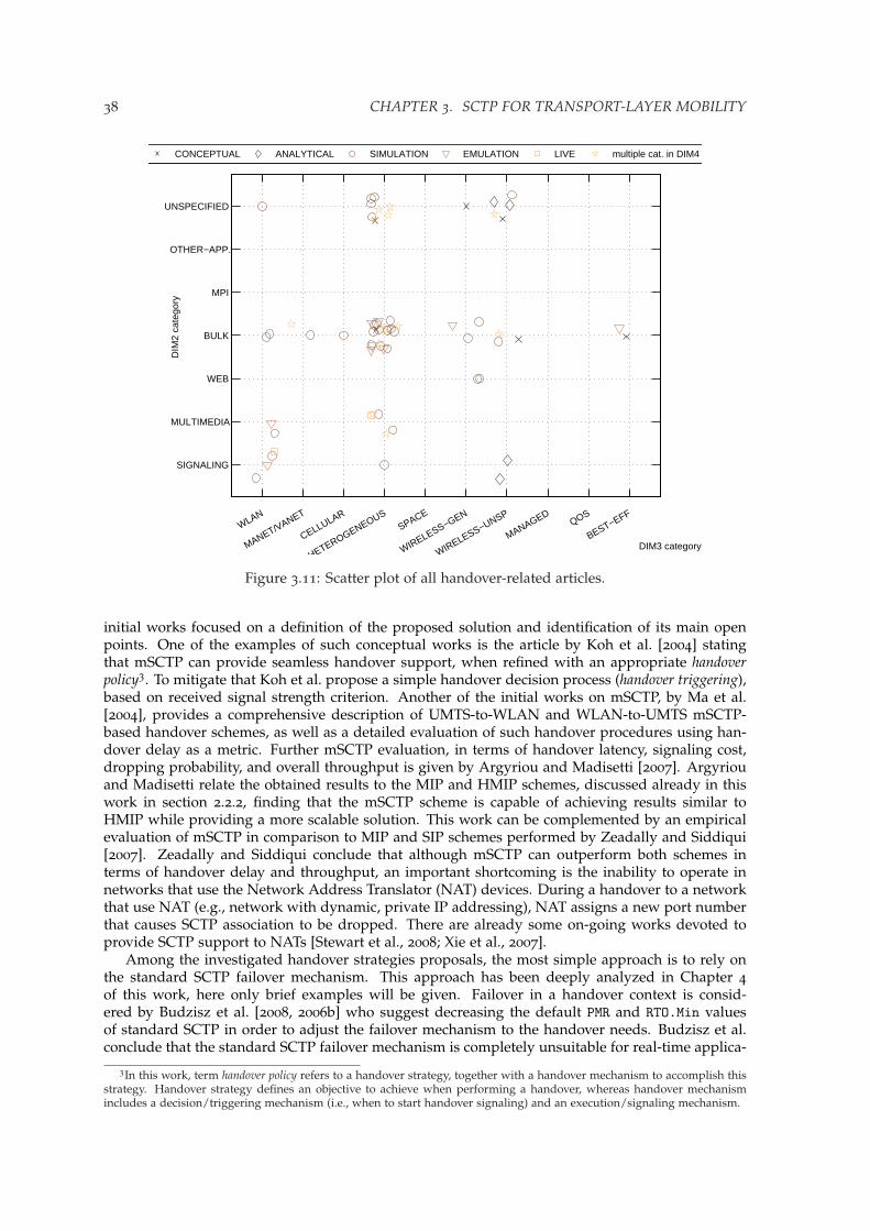
38 CHAPTER 3. SCTP FOR TRANSPORT-LAYER MOBILITY
SIGNALING
MULTIMEDIA
WEB
BULK
MPI
OTHER−APP.
UNSPECIFIED
DIM3 category
DIM
2 ca
tego
ry
WLAN
MANET/VANET
CELLULAR
HETEROGENEOUSSPACE
WIRELESS−GEN
WIRELESS−UNSP
MANAGEDQOS
BEST−EFF
CONCEPTUAL ANALYTICAL SIMULATION EMULATION LIVE multiple cat. in DIM4
Figure 3.11: Scatter plot of all handover-related articles.
initial works focused on a definition of the proposed solution and identification of its main openpoints. One of the examples of such conceptual works is the article by Koh et al. [2004] statingthat mSCTP can provide seamless handover support, when refined with an appropriate handoverpolicy3. To mitigate that Koh et al. propose a simple handover decision process (handover triggering),based on received signal strength criterion. Another of the initial works on mSCTP, by Ma et al.[2004], provides a comprehensive description of UMTS-to-WLAN and WLAN-to-UMTS mSCTP-based handover schemes, as well as a detailed evaluation of such handover procedures using han-dover delay as a metric. Further mSCTP evaluation, in terms of handover latency, signaling cost,dropping probability, and overall throughput is given by Argyriou and Madisetti [2007]. Argyriouand Madisetti relate the obtained results to the MIP and HMIP schemes, discussed already in thiswork in section 2.2.2, finding that the mSCTP scheme is capable of achieving results similar toHMIP while providing a more scalable solution. This work can be complemented by an empiricalevaluation of mSCTP in comparison to MIP and SIP schemes performed by Zeadally and Siddiqui[2007]. Zeadally and Siddiqui conclude that although mSCTP can outperform both schemes interms of handover delay and throughput, an important shortcoming is the inability to operate innetworks that use the Network Address Translator (NAT) devices. During a handover to a networkthat use NAT (e.g., network with dynamic, private IP addressing), NAT assigns a new port numberthat causes SCTP association to be dropped. There are already some on-going works devoted toprovide SCTP support to NATs [Stewart et al., 2008; Xie et al., 2007].
Among the investigated handover strategies proposals, the most simple approach is to rely onthe standard SCTP failover mechanism. This approach has been deeply analyzed in Chapter 4of this work, here only brief examples will be given. Failover in a handover context is consid-ered by Budzisz et al. [2008, 2006b] who suggest decreasing the default PMR and RTO.Min valuesof standard SCTP in order to adjust the failover mechanism to the handover needs. Budzisz et al.conclude that the standard SCTP failover mechanism is completely unsuitable for real-time applica-
3In this work, term handover policy refers to a handover strategy, together with a handover mechanism to accomplish thisstrategy. Handover strategy defines an objective to achieve when performing a handover, whereas handover mechanismincludes a decision/triggering mechanism (i.e., when to start handover signaling) and an execution/signaling mechanism.
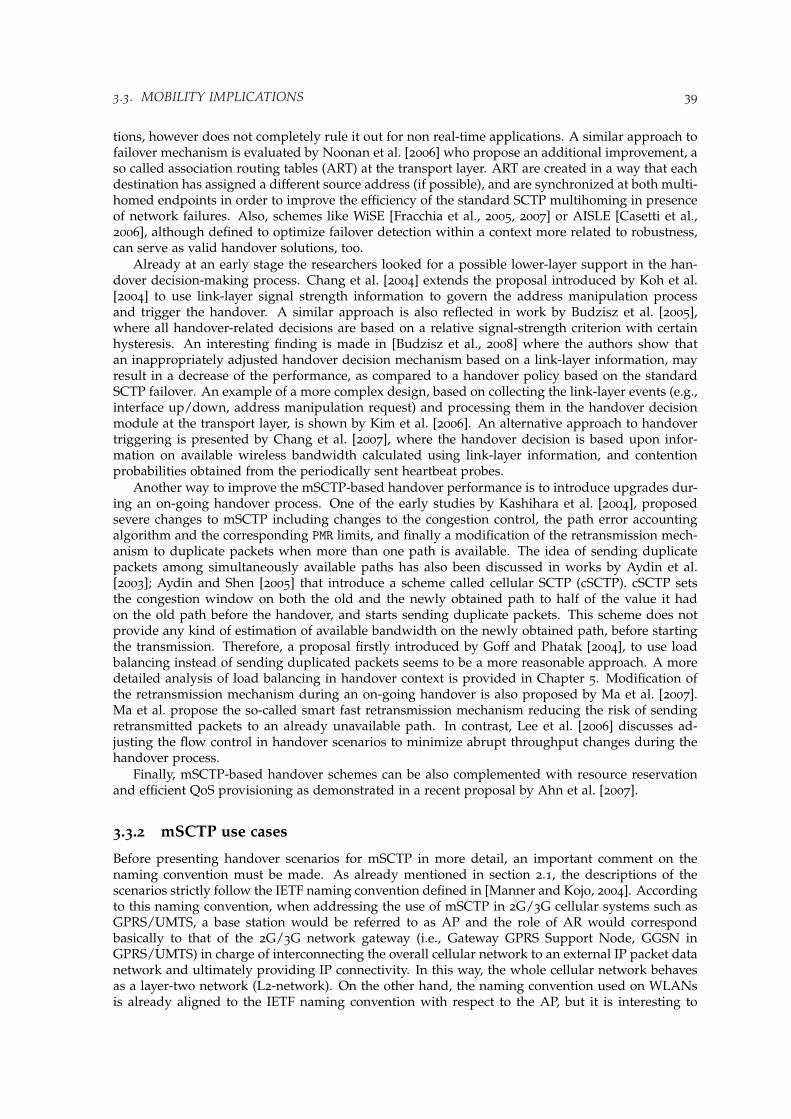
3.3. MOBILITY IMPLICATIONS 39
tions, however does not completely rule it out for non real-time applications. A similar approach tofailover mechanism is evaluated by Noonan et al. [2006] who propose an additional improvement, aso called association routing tables (ART) at the transport layer. ART are created in a way that eachdestination has assigned a different source address (if possible), and are synchronized at both multi-homed endpoints in order to improve the efficiency of the standard SCTP multihoming in presenceof network failures. Also, schemes like WiSE [Fracchia et al., 2005, 2007] or AISLE [Casetti et al.,2006], although defined to optimize failover detection within a context more related to robustness,can serve as valid handover solutions, too.
Already at an early stage the researchers looked for a possible lower-layer support in the han-dover decision-making process. Chang et al. [2004] extends the proposal introduced by Koh et al.[2004] to use link-layer signal strength information to govern the address manipulation processand trigger the handover. A similar approach is also reflected in work by Budzisz et al. [2005],where all handover-related decisions are based on a relative signal-strength criterion with certainhysteresis. An interesting finding is made in [Budzisz et al., 2008] where the authors show thatan inappropriately adjusted handover decision mechanism based on a link-layer information, mayresult in a decrease of the performance, as compared to a handover policy based on the standardSCTP failover. An example of a more complex design, based on collecting the link-layer events (e.g.,interface up/down, address manipulation request) and processing them in the handover decisionmodule at the transport layer, is shown by Kim et al. [2006]. An alternative approach to handovertriggering is presented by Chang et al. [2007], where the handover decision is based upon infor-mation on available wireless bandwidth calculated using link-layer information, and contentionprobabilities obtained from the periodically sent heartbeat probes.
Another way to improve the mSCTP-based handover performance is to introduce upgrades dur-ing an on-going handover process. One of the early studies by Kashihara et al. [2004], proposedsevere changes to mSCTP including changes to the congestion control, the path error accountingalgorithm and the corresponding PMR limits, and finally a modification of the retransmission mech-anism to duplicate packets when more than one path is available. The idea of sending duplicatepackets among simultaneously available paths has also been discussed in works by Aydin et al.[2003]; Aydin and Shen [2005] that introduce a scheme called cellular SCTP (cSCTP). cSCTP setsthe congestion window on both the old and the newly obtained path to half of the value it hadon the old path before the handover, and starts sending duplicate packets. This scheme does notprovide any kind of estimation of available bandwidth on the newly obtained path, before startingthe transmission. Therefore, a proposal firstly introduced by Goff and Phatak [2004], to use loadbalancing instead of sending duplicated packets seems to be a more reasonable approach. A moredetailed analysis of load balancing in handover context is provided in Chapter 5. Modification ofthe retransmission mechanism during an on-going handover is also proposed by Ma et al. [2007].Ma et al. propose the so-called smart fast retransmission mechanism reducing the risk of sendingretransmitted packets to an already unavailable path. In contrast, Lee et al. [2006] discusses ad-justing the flow control in handover scenarios to minimize abrupt throughput changes during thehandover process.
Finally, mSCTP-based handover schemes can be also complemented with resource reservationand efficient QoS provisioning as demonstrated in a recent proposal by Ahn et al. [2007].
3.3.2 mSCTP use cases
Before presenting handover scenarios for mSCTP in more detail, an important comment on thenaming convention must be made. As already mentioned in section 2.1, the descriptions of thescenarios strictly follow the IETF naming convention defined in [Manner and Kojo, 2004]. Accordingto this naming convention, when addressing the use of mSCTP in 2G/3G cellular systems such asGPRS/UMTS, a base station would be referred to as AP and the role of AR would correspondbasically to that of the 2G/3G network gateway (i.e., Gateway GPRS Support Node, GGSN inGPRS/UMTS) in charge of interconnecting the overall cellular network to an external IP packet datanetwork and ultimately providing IP connectivity. In this way, the whole cellular network behavesas a layer-two network (L2-network). On the other hand, the naming convention used on WLANsis already aligned to the IETF naming convention with respect to the AP, but it is interesting to

40 CHAPTER 3. SCTP FOR TRANSPORT-LAYER MOBILITY
Old Path [IPCN ,IPMN]
Correspondent
Node
IPCN
L2-networkInternet
Access
RouterAccess
Network
Gateway
Mobile
Node
IPMN
Mobile
Node
IPMN
New Path [IPCN ,IPMN]
Old
AP
New
AP
Figure 3.12: Scenario A – The IP address is not changed in the handover process.
remark here that wireless routers (devices with co-located AP and AR functionalities) are the mostcommon to find.
Scenario A. Although it was already pointed out that transport-layer solutions are targeted atscenarios where there is an IP-address change when moving from one PoA to another, we haveretained this scenario to emphasize that nowadays the most common situation is that terminalmobility only results in an AP change, while staying in the same IP subnetwork, e.g., intra-systemmobility in 2G/3G cellular networks (e.g., GSM or UMTS) or WLAN mobility within the sameExtended Service Set (ESS), as presented in Fig. 3.12.
Thus, mSCTP multihoming has no applicability here because the handover does not result in achange of the IP address used in the association. Efficient handover management can be achievedby means of link-layer solutions, so that no specific functionalities are strictly required within thetransport layer to cope with the AP change. Nevertheless, despite this possible isolation of thetransport layer from the cell-change process under such scenarios, cross-layer design constitutes anappealing research challenge to improve transport-layer performance by means of the informationavailable from lower layers.
Scenario B. Future heterogeneous wireless networks, however, will bring a lot of diversity to thenetwork structure, and terminal mobility among different radio access networks will most likelyresult in an IP-address change. Under such an assumption, the key feature of this scenario is thatterminals can only use a single radio network interface at a time (see Fig. 3.13). This limitation isfurther referred to, as the single-homed MN.
L2-network
L2-network
Old Path [IPCN, IPMN1]
Correspondent
Node
IPCN
Internet
New Path [IPCN, IPMN2]
Old
ANG
New
ANG
Old
AROld
AP
New
ARNew
AP
Mobile
Node
IPMN1
Mobile
Node
IPMN2
Figure 3.13: Scenario B – Single-homed MN.
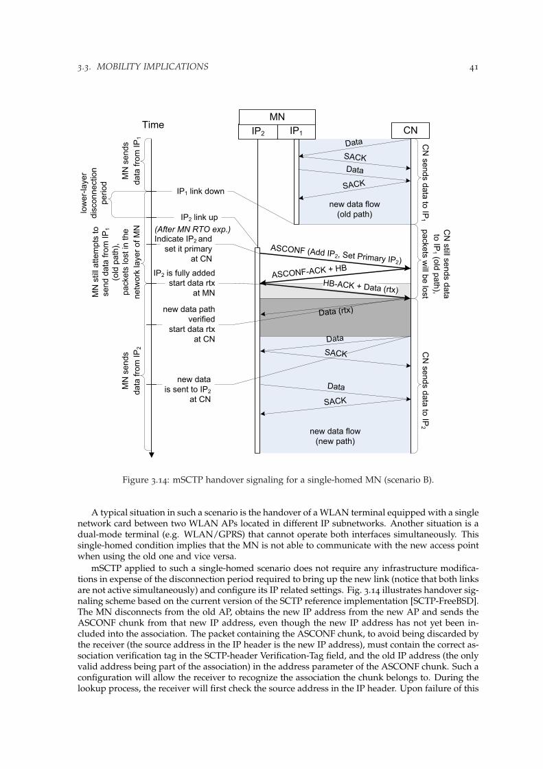
3.3. MOBILITY IMPLICATIONS 41
new data flow
(new path)
new data flow
(old path)
IP1IP2 CN
Data
SACK
ASCONF (Add IP2, Set Primary IP2)
ASCONF-ACK + HB
SACK
Time
IP2 link up
Indicate IP2 and
set it primary
at CN
IP2 is fully added
start data rtx
at MN
IP1 link down
MN
new data
is sent to IP2
at CN
Data
SACK
CN
se
nd
s d
ata
to IP
1
CN
still s
ends d
ata
to IP
1(o
ld p
ath
),
packets
will b
e lo
st
MN
sends
data
fro
m I
P1
low
er-
layer
dis
connection
period
MN
still
attem
pts
to
send d
ata
fro
m IP
1
(old
path
),
packets
lost
in t
he
netw
ork
layer
of
MN
CN
se
nd
s d
ata
to IP
2
MN
sen
ds
data
fro
m IP
2
HB-ACK + Data (rtx)
(After MN RTO exp.)
new data path
verified
start data rtx
at CN
Data (rtx)
Data
SACK
Data
Figure 3.14: mSCTP handover signaling for a single-homed MN (scenario B).
A typical situation in such a scenario is the handover of a WLAN terminal equipped with a singlenetwork card between two WLAN APs located in different IP subnetworks. Another situation is adual-mode terminal (e.g. WLAN/GPRS) that cannot operate both interfaces simultaneously. Thissingle-homed condition implies that the MN is not able to communicate with the new access pointwhen using the old one and vice versa.
mSCTP applied to such a single-homed scenario does not require any infrastructure modifica-tions in expense of the disconnection period required to bring up the new link (notice that both linksare not active simultaneously) and configure its IP related settings. Fig. 3.14 illustrates handover sig-naling scheme based on the current version of the SCTP reference implementation [SCTP-FreeBSD].The MN disconnects from the old AP, obtains the new IP address from the new AP and sends theASCONF chunk from that new IP address, even though the new IP address has not yet been in-cluded into the association. The packet containing the ASCONF chunk, to avoid being discarded bythe receiver (the source address in the IP header is the new IP address), must contain the correct as-sociation verification tag in the SCTP-header Verification-Tag field, and the old IP address (the onlyvalid address being part of the association) in the address parameter of the ASCONF chunk. Such aconfiguration will allow the receiver to recognize the association the chunk belongs to. During thelookup process, the receiver will first check the source address in the IP header. Upon failure of this
42 CHAPTER 3. SCTP FOR TRANSPORT-LAYER MOBILITY
attempt (the new address is still not a part of the association), the receiver will eventually get theappropriate IP address from the ASCONF-chunk address-parameter field. The lookup process isfollowed by the validation of the verification tag, and chunk processing. Bundling of all operationsof address manipulation in one chunk is allowed by DAR extension specification [Stewart et al.,2007], and is subject to a handover policy. The only requirements is that the ASCONF chunk pa-rameters should be transmitted in the appropriate order, that is: Add new-IP address, Delete old-IPaddress, and Set primary address to new-IP address, in order not to be discarded when process-ing at the receiver. The receiver must then reply to the source IP address of the packet that, afterprocessing all of the ASCONF chunk parameters, is the only IP address included in the association.The described mechanism has strong implications on security, and, as mentioned in Section 3.1.3,an authentication procedure is required before processing the ASCONF chunk to avoid the risk ofassociation hijacking, as described in [Stewart et al., 2007] and [Stewart, Tuexen, and Camarillo,2007].
The scheme shown in Fig. 3.14 is prone to long handover delays. Apart from the lower-layerdisconnection period, also transport-layer contributes to an overall long handover latency. Thetransport-layer part of the handover latency can be mitigated, if several handover-oriented optimiza-tions are considered. An example of such a handover-optimized scheme is SmSCTP, introducedby Honda et al. [2007], illustrated here in Fig. 3.15. Honda et al. propose to send the ASCONFchunk with the request to add the new IP address, as soon as the new address becomes available,i.e., without waiting for the RTO expiration on the current primary path. This is possible witha slight modification in the approach to the path definition, and thus to the congestion handling.New source address from which the ASCONF chunk will be sent, may be treated as the new path, ifonly the path is identified by the pair of source-destination address, instead of destination addressonly, as in case of the reference implementation. Such a modification is still in line with protocolspecification, which simply does not require the control of the source address in the path definition.Consequently, retransmitted data can be sent as soon as the new path is available, that is in case ofdata sent from the MN after the ASCONF-ACK chunk arrives, and for data sent from CN as soonas the new path is verified (when HB-ACK arrives).
Apart from the commented modification, the main challenge in such a handover scenario is tokeep system performance during the path-transition phase (i.e., from the moment, the MN has senta message with the Add IP Address and Set Primary Address option, until the transmission hasstarted on the new address). In particular, to minimize the layer-two disconnection period, andconsequently avoid mSCTP timeout retransmissions being sent on the already inactive path.
Alternatively, to overcome limitations of the single-homed scenario, the radio access network cancontain an extension facilitating the acquisition of a new IP address through the old AP. An exampleof such an extension is the Candidate Access Router Discovery (CARD) protocol that providescommunication with the new AP through the old AP in order to obtain the new IP address, asshown in [Liebsch et al., 2005].
Scenario C. In this scenario, the MN is multi-homed, that is, more than one network interface canbe operated simultaneously. However, regarding CN connectivity, a single-homed CN is assumedso that the CN is only reachable through a unique IP address. Fig. 3.16 illustrates this asymmetricscenario involving a dual-homed MN connected to a single-homed CN.
As most Internet servers nowadays are configured with only one IP address, this scenario islikely to become the most common in today’s heterogeneous landscape. Under such conditions,mSCTP can be applied to provide seamless handover between two APs connected to different sub-nets. The main phases in the handover process are shown in Fig. 3.17 and explained below:
1. Once a candidate AP has been selected, an IP address valid for the new location must beobtained. New addresses can be obtained via, e.g., DHCP, DHCPv6 or stateless IPv6 auto-configuration in the new location.
2. The new IP address is signaled to the mSCTP stack of the MN node. The time periodwhen the two different network addresses are effectively available at the transport layer (i.e.,including necessary transport-layer signaling before any DATA chunks can be transmitted)will be further referred as a dwelling time in this work.

3.3. MOBILITY IMPLICATIONS 43
new data flow
(new path)
new data flow
(old path)
IP1IP2 CN
Data
SACK
ASCONF (Add IP2, Set Primary IP2,Remove IP1)
SACK
Time
IP2 link up
indicate IP2 and
set it primary
at CN
remove IP1
IP1 link down
MN
new data
is sent to IP2
at CN
Data
SACK
CN
se
nd
s d
ata
to IP
1
CN
still s
ends d
ata
to IP
1(o
ld p
ath
),
packets
will b
e lo
st
MN
sends
data
fro
m I
P1
low
er-
layer
dis
connection
pe
rio
dM
N s
till
attem
pts
to
send d
ata
fro
m IP
1
(old
path
),
packets
lost
in t
he
ne
two
rk la
ye
r o
f M
N
CN
sends d
ata
to IP
2
MN
sen
ds
data
fro
m IP
2
HB-ACK + Data (rtx)
new path
verified
start data rtx
at CN
Data (rtx)
Data
ASCONF-ACK + HB
SACK
Data
IP2 is fully added
start rtx data
at MN
Figure 3.15: Optimized mSCTP handover scheme for a single-homed MN (scenario B).

44 CHAPTER 3. SCTP FOR TRANSPORT-LAYER MOBILITY
L2-network
L2-network
Old Path [IPCN, IPMN1]
Correspondent
Node
IPCN
Internet
New Path [IPCN, IPMN2]
Old
ANG
New
ANG
Old
AROld
AP
New
ARNew
AP
MN
IPMN1
MN
IPMN1, IPMN2
MN
IPMN2
Figure 3.16: Scenario C – Single-homed CN, Dual-homed MN.
3. mSCTP on the MN must notify the CN of the new address — the Add new /IP addressrequest is sent.
4. The CN confirms the incorporation of the new address into the association. As in case ofsingle-homed MN, ASCONF-ACK chunk is usually bundled with the HB chunk used inpath verification process. At that time, data from the CN towards the MN is still sent onthe old path, as the primary-path change has not been requested yet. On the other hand,once the ASCONF-ACK chunk arrives at the MN, data coming from the MN can be sent tothe CN from any of the two available source addresses, depending on MN’s routing tableconfiguration.
5. Then, at an adequate moment (possibly the most important open issue is how to determinewhen to switch the primary path) the primary-path change is triggered by the MN, as it iscommonly assumed that the handover decision is mainly related to the status of the radiolink between the MN and the APs (handover decision can be based on any other criteria,depending on the handover policy that is applied). The primary path change procedure isstarted by sending an ASCONF chunk with the Set Primary Address parameter pointing tothe new path.
6. The CN switches to the new path as soon as the ASCONF chunk with the primary-path-change-request arrives at the CN. The new path had already been verified, so it is usedimmediately, first to retransmit any chunks that need to be retransmitted (if any), and thento send new data to the MN.
7. Also, as soon as the connection with the old AP is lost, the unnecessary IP address shouldbe removed by means of a Delete IP Address request. Depending on the handover policy,removing of the old IP address can be bundled with the primary-path-change-request. Againit is important to follow the appropriate order of parameters (same as described in a single-homed case) to avoid discarding of the ASCONF chunk.
Consequently, the main challenges in this scenario are related to path management (i.e., criteriato trigger the primary path change) and path transition optimization (e.g., reducing the slow-startphase on the new path, etc.). In that sense the handover policy plays the crucial role in many ways,e.g., (1) handover strategy aims to optimize the use of available resources; (2) handover trigger-ing mechanism may reduce handover latency by indicating the most appropriate time-instance toinitiate the handover; and (3) handover execution mechanisms may be simplified by bundling aSet Primary with Add/Delete IP Address parameter within one ASCONF chunk. Inappropriatehandover policy may result in degradation of the overall performance. To give the reader moreinsight on this issue, a range of possible adjustments of handover policies is illustrated with twoextreme situations, referred to as best case (Fig. 3.18a) and worst case (Fig. 3.18b), respectively. Thesample handover scenario in the presented examples consists of a MN moving from the slower(IP1) to faster AN (IP2). Thus, in such a handover scenario, the best case policy results in the pathchange, as soon as the new interface is available, whereas the worst case policy waits excessivelylong, leading to a lower-layer disconnection period, before switching to the new path.

3.3. MOBILITY IMPLICATIONS 45
new data flow
(new primary path only)
new data flow
(old primary path only)
IP1IP2 CN
Data
SACK
ASCONF (Add IP2)
ASCONF-ACK + HB
ASCONF (Set Primary IP2,Remove IP1)
SACK
HB-ACK + Data
Time
Dw
elli
ng t
ime
IP2 link up,
indicate IP2
to CN
IP2 is fully
added
MN can transmit
new data
from IP2
IP1 link down
set IP2
primary at CN
and remove IP1
start data rtx
to IP2 at CN
Pote
ntial
dis
connection p
eriod
MN
new data
is sent to IP2
at CN
Data
is s
ent to
IP1
Data
is s
till sent to
IP1
(prim
ary
path
),
packets
will b
e lo
st
Data
is s
en
t to IP
2
ASCONF-ACK + Data (rtx)
Data
SACKMN
sends
data
fro
m IP
1
MN
ca
n s
en
d d
ata
from
either
IP1
or
IP2
MN
se
nd
s
data
fro
m IP
2
IP1 is
considered
removedSACK
Data
Data
(1)
(2)
(3)
(4)
(6)
(5), (7)
Figure 3.17: mSCTP handover signaling for the asymmetric scenario (scenario C).

46 CHAPTER 3. SCTP FOR TRANSPORT-LAYER MOBILITY
new data flow
(old primary path only)
new data flow(new primary path only)
IP1IP2 CN
Data
SACK
ASCONF (Add IP2, Set Primary IP2,Remove IP1)
ASCONF-ACK + HB
SACK
HB-ACK + Data
Time
Dw
elli
ng t
ime
IP2 link up,
indicate IP2 andset it primary
at CN,remove IP1
IP2 is fully
addedMN sends data
from IP2
IP1 link down
MN
Data
is s
ent to
IP1
Data
is s
ent to
IP2
MN
se
nd
s d
ata
fro
mIP
1M
N s
ends d
ata
fro
m IP
2
new path is
verified CN sends data
to IP2
SACK
Data
Data + SACK
(a)
Figure 3.18: mSCTP handover scheme for the asymmetric scenario with different handover policies(scenario C): (a) best case.

3.3. MOBILITY IMPLICATIONS 47
new data flow
(new primary path only)
new data flow
(old primary path only)
IP1IP2 CN
Data
SACK
ASCONF (Add IP2, Set Primary IP2,Remove IP1)
ASCONF-ACK + HB
SACK
HB-ACK + Data (rtx)
Time
Dw
elli
ng
tim
e IP2 link up
indicate IP2 and
set it primary
at CN,remove IP1
IP2 is fully
addedstart data rtx
from IP2 at MN
IP1 link down
new path is
verified
start data rtxto IP2 at CN
Dis
connection
pe
rio
d
MN
new data is sent to IP2
at CN
Data
is s
ent to
IP1
Data
is s
till sent to
IP1
(prim
ary
path
),
packets
will b
e lo
st
Data
is s
en
t to IP
2
Data
SACKMN
sends
da
ta f
rom
IP1
MN
sends
da
ta f
rom
IP2
Data
SACK
Data (rtx) + SACK
(b)
Figure 3.18: mSCTP handover scheme for the asymmetric scenario with different handover policies(scenario C): (b) worst case.

48 CHAPTER 3. SCTP FOR TRANSPORT-LAYER MOBILITY
new data flow
(new primary path only)
Handle rtx
new data flow(old primary path only)
IP1IP2 CN
Data
SACK
ASCONF (Add IP2)
ASCONF-ACK + HB
Data
SACK
HB-ACK
Time
Dw
elli
ng tim
e
IP2 link up -Indicate IP2
to CN
IP2 is fully added
IP1 link down
Rtx are sent to IP2
Dis
connection
period
MN
new data
is sent to IP2
Rtx
handlin
g
period
Data
is s
ent to
IP1
Data
is s
en
t to IP
2F
ailo
ver
IP2 is verified
SACK
Data (rtx)
(c)
Figure 3.18: mSCTP handover scheme for the asymmetric scenario with different handover policies(scenario C): (c) failover-based policy.
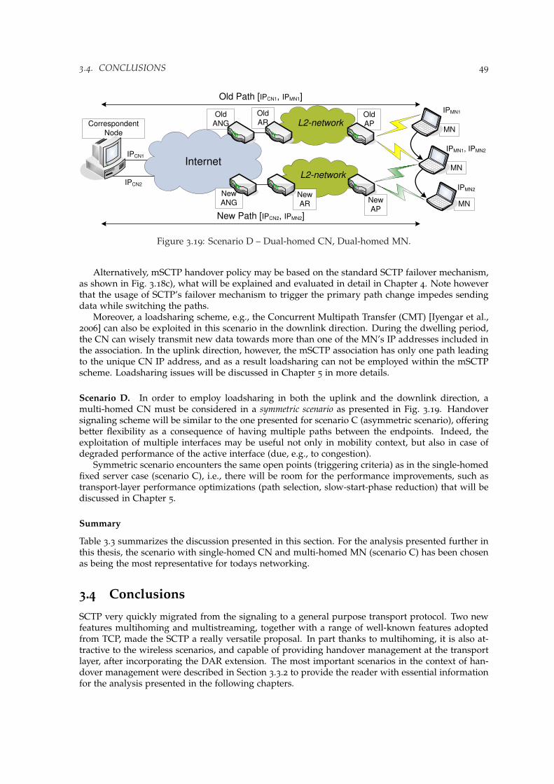
3.4. CONCLUSIONS 49
L2-network
L2-network
Old Path [IPCN1, IPMN1]
Correspondent
Node
IPCN2
Internet
New Path [IPCN2, IPMN2]
Old
ANG
New
ANG
Old
AROld
AP
New
ARNew
AP
IPCN1
MN
IPMN1
MN
IPMN1, IPMN2
MN
IPMN2
Figure 3.19: Scenario D – Dual-homed CN, Dual-homed MN.
Alternatively, mSCTP handover policy may be based on the standard SCTP failover mechanism,as shown in Fig. 3.18c), what will be explained and evaluated in detail in Chapter 4. Note howeverthat the usage of SCTP’s failover mechanism to trigger the primary path change impedes sendingdata while switching the paths.
Moreover, a loadsharing scheme, e.g., the Concurrent Multipath Transfer (CMT) [Iyengar et al.,2006] can also be exploited in this scenario in the downlink direction. During the dwelling period,the CN can wisely transmit new data towards more than one of the MN’s IP addresses included inthe association. In the uplink direction, however, the mSCTP association has only one path leadingto the unique CN IP address, and as a result loadsharing can not be employed within the mSCTPscheme. Loadsharing issues will be discussed in Chapter 5 in more details.
Scenario D. In order to employ loadsharing in both the uplink and the downlink direction, amulti-homed CN must be considered in a symmetric scenario as presented in Fig. 3.19. Handoversignaling scheme will be similar to the one presented for scenario C (asymmetric scenario), offeringbetter flexibility as a consequence of having multiple paths between the endpoints. Indeed, theexploitation of multiple interfaces may be useful not only in mobility context, but also in case ofdegraded performance of the active interface (due, e.g., to congestion).
Symmetric scenario encounters the same open points (triggering criteria) as in the single-homedfixed server case (scenario C), i.e., there will be room for the performance improvements, such astransport-layer performance optimizations (path selection, slow-start-phase reduction) that will bediscussed in Chapter 5.
Summary
Table 3.3 summarizes the discussion presented in this section. For the analysis presented further inthis thesis, the scenario with single-homed CN and multi-homed MN (scenario C) has been chosenas being the most representative for todays networking.
3.4 Conclusions
SCTP very quickly migrated from the signaling to a general purpose transport protocol. Two newfeatures multihoming and multistreaming, together with a range of well-known features adoptedfrom TCP, made the SCTP a really versatile proposal. In part thanks to multihoming, it is also at-tractive to the wireless scenarios, and capable of providing handover management at the transportlayer, after incorporating the DAR extension. The most important scenarios in the context of han-dover management were described in Section 3.3.2 to provide the reader with essential informationfor the analysis presented in the following chapters.

50 CHAPTER 3. SCTP FOR TRANSPORT-LAYER MOBILITY
Table3.3:Sum
mary
ofm
SCTP
applicationscenarios.
Feature
Scena
rioA
Scena
rioB
Scena
rioC
Scena
rioD
IPaddress
changeduring
handover
No
YesYes
Yes
Num
berof
activeinterfaces
onthe
MN
Multihom
ingnot
availableat
thetransport
layer
One
(Single-homed
Many
(Multi-hom
ed)M
any(M
ulti-homed)
Num
berof
IPaddresses
onthe
CN
Not
important
Not
important
Single-homed
Multi-hom
ed
TypicalscenariosIntra-system
handoverin
2G/3G
Cellular
orW
LAN
networks
Inter-systemhandover
inheterogeneous
networks
Inter-systemhandover
inheterogeneous
networks
Inter-systemhandover
inheterogeneous
networks
Main
openissues
Cross-layer
designto
enhancetransport-layer
performance
duringhandover
process(e.g.,
link-layershort
inter-ruption,
delayspikes,
packetbursts
losses)
—IP
configurationof
thenew
linkw
ithoutaffecting
theSC
TPoperation
atthe
currentlink
—Path
transitionoptim
ization
—Loadsharing
ondow
nlinkonly
—H
andovertriggering
criteria—
Pathtransition
optimization
—Loadsharing
onup-/dow
nlink—
Handover
triggeringcriteria
—Path
transitionoptim
ization

Chapter 4
Failover as a basic handover scheme
Standard SCTP provides a failover mechanism to manage transmission over multiple paths whenavailable, increasing therefore protocol robustness in presence of link failures. Nevertheless, limit-ing the use of multihoming strictly to the failover upon link failure event seems a drawback of thestandard SCTP. Already SCTP failover itself can be reused for other purposes, e.g., as a basic mech-anism triggering handover in a mSCTP handover scheme, as shown in Fig. 3.18c. This approachmeans that switching among the multiple paths between the endpoints is only conducted attendingto the information available at the transport layer (e.g., no triggering conditions from lower lay-ers are used). This interesting idea will be evaluated in this chapter quantifying the feasibility ofthe proposed solution for heterogeneous wireless networks. Before that, a detailed description ofthe failover mechanism will be given, providing the reader with the necessary background for thepresented analysis.
4.1 Description of the SCTP failover mechanism
Reliability in SCTP is forced with an important protocol feature, multihoming. To detect a pathfailure each multihomed SCTP endpoint uses both implicit and explicit probes. Transmitted dataserves as an implicit probe used to monitor the availability of the primary path. SCTP keeps anerror counter that counts the number of consecutive timeouts. If the error counter reaches a certaintunable threshold, Path.Max.Retrans (PMR), the primary path is considered unavailable. However,if a SACK chunk is received before the error counter reaches PMR, the error counter is reset to zero.A persistent failure to reach the primary destination eventually induces a failover, at which thesource endpoint selects one of the available alternate paths as a new primary path.
Since no data chunks are normally sent on the alternate paths, SCTP uses explicit probes, calledHEARTBEATs to monitor the availability of such idle paths. HB chunks are periodically sent onthe alternate paths at a rate governed by a tunable heartbeat timer, in function of HeartbeatInterval(HBInt) parameter. If a HB-ACK chunk is not received before the heartbeat timer expires, an errorcounter is incremented. Again, if the error counter reaches PMR, the corresponding alternate path isconsidered unavailable.
Subject of a discussion in this chapter, the standard SCTP failover mechanism, illustrated inFig. 4.1, is based on the retransmission timer (T3-rtx timer) derived from the TCP, together with itsmanaging rules, defined in [Paxon and Allman, 2000]. The retransmission timer is used to clockevery data chunk sent to the corresponding peer in order to guarantee a reliable delivery. Upontransmission of a new data chunk the T3-rtx timer is set to the value of RTO, based on the currentRTT measurements, according to the formula (4.2).

52 CHAPTER 4. FAILOVER AS A BASIC HANDOVER SCHEME
Receiver
PRIMARY
Interface SENDER
Receiver
BACKUP
Interface
Path failure
1st
timeout
...
Backup
retransmission
2nd
timeout
1 new packet
Failover to a new path
(PMR+1)th
timeout
Retransmission
of 1 packet
Send new data
up to fill cwndbk
fail
data
SACK
1 new packet
Backup
retransmission
...
Figure 4.1: SCTP failover mechanism.

4.1. DESCRIPTION OF THE SCTP FAILOVER MECHANISM 53
Before the first RTT measurement is made: RTO = RTOinit (4.1)If at least one RTT measurement (R’) is made:
RTO = SRTT + 4 · RTTVAR (4.2)where:
with first measurement:SRTT = R′ and RTTVAR = R′/2 (4.3)
with any subsequent measurement:SRTT = (1− α) · SRTT + α · R′ (4.4)
RTTVAR = (1− β) · RTTVAR + β · ∣∣SRTT− R′∣∣ (4.5)
If the T3-rtx timer expires, and the data chunk has not yet been acknowledged by the remotepeer, a so-called retransmission timeout (RTO) event, it is assumed that the chunk is lost, and theactual RTO value for the affected path is doubled (exponential back-off mechanism). The lost chunk,together with all the chunks that were in transition (in flight) towards the corresponding peer inthe moment the T3-rtx timer expired, are marked for retransmission, while the outstanding datacounter for that path is reset to zero. Then, SCTP starts retransmitting lost chunks according toits retransmission policy. The SCTP specification [Stewart, 2007] recommends sending timeoutretransmissions on the alternate path, provided, of course, that there is an alternate path available.The first retransmission includes all marked chunks that fit into a single data packet. Remainingmarked chunks are retransmitted as soon as the congestion window on the alternate path allowsit. In order to clock the retransmitted data, the T3-rtx timer on the alternate path is restarted, withthe current RTO value of that path. This is the main difference with respect to TCP, which hasto send all retransmissions on the same, unique path. Although retransmissions are sent on thealternate path, new data is still sent on the primary path. Thus if the path failure is persistent, asthe one shown in Fig. 4.1, additional timeouts will occur. The maximum number of consecutivetimeouts on the primary path is limited by PMR. Once this threshold value is exceeded, the pathis considered inactive, and a new primary path is selected among the alternate paths that arecurrently available1. The protocol fails over to the selected path (path selection is implementationspecific, RFC recommends round robin fashion), and from this point on, all data chunks are sent tothe new primary path. Following this discussion, and as seen in Fig. 4.1, the failover time (Tf ail) canbe defined as the interval between the time when the primary path becomes unavailable, and thetime, at which the first new data packet is transmitted on the new primary path.
In case of a persistent failure on the primary path, the SCTP literature usually proposes a roughestimation of the failover time [Stewart and Xie, 2001]. This rough estimation is based on the sumof consecutive timeout periods, analogously to the back-off timer mechanism of SCTP’s ancestor,TCP. Indeed, the sum of the PMR consecutive timeouts, called here total primary path RTO expira-tions time (TRTO) is the most important factor in the SCTP failover time estimation. TRTO is givenby equation (4.6), combining the RTO value at the time of the path failure (RTO f ail), and bothupper and lower bound for the RTO value: RTO.Max (RTOMax) and RTO.Min (RTOMin) accordingly, asrecommended by the SCTP specification [Stewart, 2007].
Tf ail ≈ TRTO =PMR
∑i=0
min(
max(RTOMin; 2i ·RTO f ail
); RTOMax
)(4.6)
Obviously, the maximum number of allowed retransmissions (PMR) determines the impact ofthe exponential back-off mechanism in SCTP. Protocol specifications recommend setting PMR tofive, which for the lowest RTO f ail allowed by the RTOMin default setting (1 s), yields a 63 second-longfailover time. This is unacceptably long for the majority of communication applications. Caro [2005]demonstrates that an improvement of this behavior may be achieved by decreasing the PMR value.
1The total number of consecutive timeouts for the entire SCTP association is handled by the Association.Max.Retrans
parameter. The SCTP specifications recommend that this value should not be larger than the sum of the PMR values of all thepaths of the association.

54 CHAPTER 4. FAILOVER AS A BASIC HANDOVER SCHEME
Receiver
PRIMARY
Interface SENDER
Receiver
BACKUP
Interface
Path failure
1st
timeout
Last SACK
data
T3-rtx
re-startSACK
Figure 4.2: The last SACK offset.
As will be shown later in Section 4.3.1, transport layer mobility applications typically should havethe PMR value reduced from the default value of five to lower values (i.e., between 0 and 2) inorder to achieve shorter failover times. Therefore in such cases, there is a need to take into accountadditional factors in the estimation of the failover time.
4.2 Reference study: analytical estimation of failover time
The scheme presented in equation (4.6) for the failover time estimation has been applied in most ofthe SCTP publications so far. In paper [Budzisz et al., 2007] author aims at demonstrating that theaccuracy of the estimation based only on TRTO is not always satisfying, and specially in transportlayer mobility scenarios. The proposed update seems critical, mainly because of the two followingreasons: the lack of an exact indication of the moment when the failure occurred, and the ambiguityof the failover definition in the protocol specification. In this section both aspects will be examinedin more detail. This reference study will also serve to bring the reader more details of the failoverscheme.
The T3-rtx timer manages the data sending process and is re-started each time, a SACK arrivesthat acknowledges data with the earliest outstanding TSN (rule R3 in RFC 4960 [Stewart, 2007]).Thus, it is important to relate the moment of the path failure to the instance when the last SACKwas successfully received on the primary path, and the RTO expiration accounting was started, asillustrated in Fig. 4.2. Hereafter this time will be called the last SACK offset (TSACK). Dependingon the network state at the moment of failure, TSACK may be either negative (the T3-rtx timer wasrestarted for the last time before the link failure) or positive the last T3-rtx timer reset took placeafter the path failure, as some SACKs still managed to arrive at the sender).
Another reason for the estimation update arises from the ambiguity of the definition of thefailover mechanism in the SCTP specification. The intention of the protocol authors [Stewart, 2007]was that SCTP should be able to send new data packets to the primary path simultaneously withthe retransmission of the packets that timed out, handled on the alternate path, as it was presentedin Fig. 4.1 in Section 4.1. Since the main scope of the RFCs developed by the IETF is the protocolspecification, but not the implementation issues, there is no unique way the protocol should behave,as far as the implementation does not violate the specification rules. Author has examined the mostimportant of the existing SCTP implementations [SCTP-FreeBSD; SCTP-LK; SCTP-SS7], as well as a
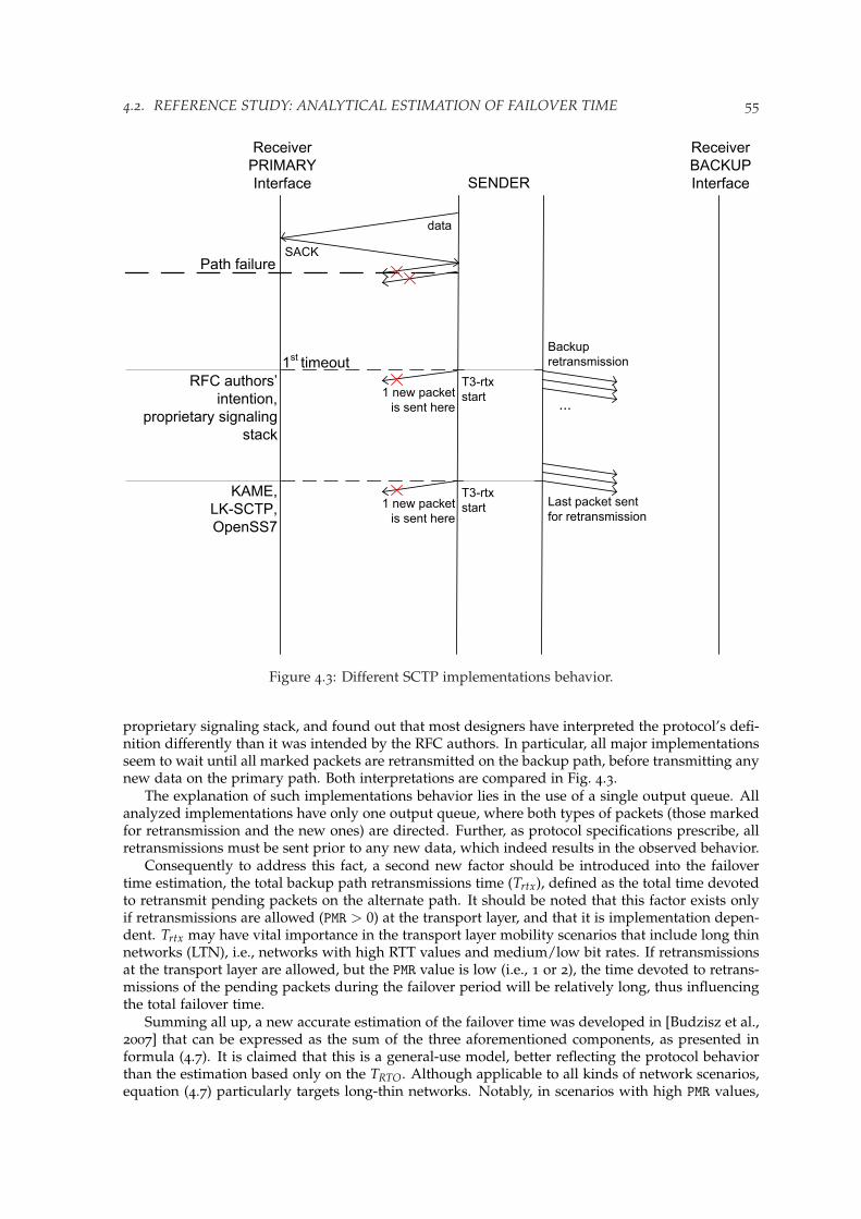
4.2. REFERENCE STUDY: ANALYTICAL ESTIMATION OF FAILOVER TIME 55
1 new packet
is sent here
Receiver
PRIMARY
Interface SENDER
Receiver
BACKUP
Interface
Path failure
1st
timeout
...
Backup
retransmission
data
SACK
1 new packet
is sent here
Last packet sent
for retransmission
RFC authors’
intention,
proprietary signaling
stack
KAME,
LK-SCTP,
OpenSS7
T3-rtx
start
T3-rtx
start
Figure 4.3: Different SCTP implementations behavior.
proprietary signaling stack, and found out that most designers have interpreted the protocol’s defi-nition differently than it was intended by the RFC authors. In particular, all major implementationsseem to wait until all marked packets are retransmitted on the backup path, before transmitting anynew data on the primary path. Both interpretations are compared in Fig. 4.3.
The explanation of such implementations behavior lies in the use of a single output queue. Allanalyzed implementations have only one output queue, where both types of packets (those markedfor retransmission and the new ones) are directed. Further, as protocol specifications prescribe, allretransmissions must be sent prior to any new data, which indeed results in the observed behavior.
Consequently to address this fact, a second new factor should be introduced into the failovertime estimation, the total backup path retransmissions time (Trtx), defined as the total time devotedto retransmit pending packets on the alternate path. It should be noted that this factor exists onlyif retransmissions are allowed (PMR > 0) at the transport layer, and that it is implementation depen-dent. Trtx may have vital importance in the transport layer mobility scenarios that include long thinnetworks (LTN), i.e., networks with high RTT values and medium/low bit rates. If retransmissionsat the transport layer are allowed, but the PMR value is low (i.e., 1 or 2), the time devoted to retrans-missions of the pending packets during the failover period will be relatively long, thus influencingthe total failover time.
Summing all up, a new accurate estimation of the failover time was developed in [Budzisz et al.,2007] that can be expressed as the sum of the three aforementioned components, as presented informula (4.7). It is claimed that this is a general-use model, better reflecting the protocol behaviorthan the estimation based only on the TRTO. Although applicable to all kinds of network scenarios,equation (4.7) particularly targets long-thin networks. Notably, in scenarios with high PMR values,

56 CHAPTER 4. FAILOVER AS A BASIC HANDOVER SCHEME
equation (4.6) gives a sufficient estimation of Tf ail , as both newly introduced factors will have lessrelevance due to the dominant role of the exponential back-off mechanism.
Tf ail = TRTO + TSACK + Trtx (4.7)
4.2.1 Best-worst case analysis
Analyzing the proposed estimation formula (4.7), it must be emphasized again that the most im-portant factor is TRTO. However, once the number of available retransmissions (PMR) is known, andthe decisive TRTO factor determined (4.6), the overall failover time can be considered as a functionof the two newly introduced factors. From that perspective, the best case (the shortest failover time)corresponds to the event when the last SACK is received at the earliest possible moment before thefailure occurs (TSACK < 0), and the new data packets are sent simultaneously with the retransmis-sions (Trtx = 0). In this case, the lower limit for the last SACK offset can be estimated as the timenecessary for data packet and its corresponding SACK to traverse the primary path (the round triptime, RTT) plus the value of SACK delay, due to the delayed SACK mechanism used by SCTP (thereceiver sends a SACK every second packet received, see Section 4.3.1 for more details). So if there isonly one packet correctly received, and the primary path failure occurs right before the correspond-ing SACK is about to be received at the sender, this produces the largest time interval between thelast SACK received and the moment of the path failure. Next if the worst case is considered, the lastdata packet received correctly should arrive at the receiver shortly before the primary path failureoccurs. Then the corresponding SACK would still be able to traverse the path, increasing thereforethe last SACK offset to half of the RTT (TSACK > 0). However, more important here is the influenceof the backup path retransmission time. If the SCTP implementation waits until all packets pendingretransmission are sent on the backup path, the resulting failover time will be considerably larger.Then, Trtx can be estimated as a function of the number of packets pending retransmission, andthe RTT expressed by means of network parameters, such as available bandwidth and latency. Anexample of such estimation will be presented in Section 4.2.2, whereas here the Tf ail best-worst caseanalysis is summarized in Table 4.1.
Table 4.1: Failover time estimation boundaries
Parameter Best case Worst case
TSACK −(SACK delay+ RTT)RTT
2Trtx 0 f (packets pending rtx; RTT) see example in Section 4.2.2
4.2.2 Estimation example
In this section, an example of an accurate estimation of Tf ail will be developed applying a more de-tailed analysis to the general-use model introduced before. Such accurate failover time estimation isespecially important when using the SCTP multihoming feature as the basis for achieving transportlayer mobility in wireless networking scenarios, an application field being subject to intensive re-search nowadays. The reason is twofold. First, most mobile wireless networks can be categorized aslong-thin networks. Second, an accurate knowledge of the transition time between available pathsis one of the key prerequisites for handover optimization.
A common scenario, when analyzing SCTP multihoming performance in the context of transportlayer mobility, consists of two paths (primary and backup) between two network hosts, e.g. a mobilenode and a server, as depicted in Fig. 4.4. Under such scenario it is assumed that the server issending data to the mobile node that is initially reachable through two IP addresses. Suddenly,due to the problems on the wireless link or as a consequence of user mobility, the address used asthe primary becomes unreachable, and the server has to fail over to the alternate path using thestandard SCTP failover mechanism.

4.2. REFERENCE STUDY: ANALYTICAL ESTIMATION OF FAILOVER TIME 57
L2-network
L2-network
Primary Path:
Correspondent
Node
IPCN
Internet
Backup Path:
Old
ANG
New
ANG
Old
AROld
AP
New
AR
New
AP
MN
IPMN1, IPMN2
MN
IPMN2
Bpr_wired,Tpr_lat_wired
Bbk_wireless,Tbk_lat_wirelessBbk_wired,Tbk_lat_wired
Bpr_wireless,Tpr_lat_wireless
Figure 4.4: Simulation scenario.
In the presented example, the proposed estimation of the failover time is based on the followingparameters that model the overall network behavior:
• Link bandwidth for the primary and backup paths denoting separately the wired (Bpr wiredand Bbk wired), and wireless parts (Bpr wireless and Bbk wireless),
• Latency corresponding to the wired and wireless (bottleneck) part on each of the paths (pri-mary path: Tlat pr wired, Tlat pr wireless, and backup path: Tlat bk wired, Tlat bk wireless, respectively).Moreover, the total path latency for each path is also indicated (Tlat pr and Tlat bk).
In addition, the following two parameters are assumed to be known at the time of the path failure:• Congestion window (cwnd f ail),• Retransmission time out value (RTO f ail).
It is also assumed that the receiver window size (rwnd) is not affecting the failover performance,i.e., it is not limiting the number of packets retransmitted on the alternate path.
Now, when examining the first of the two introduced factors, TSACK, it is important to relate themoment of the path failure to the instance when a SACK was received for the last time, and the RTOexpiration accounting was started. In the instance, when the path failure occurs, all SACKs in flightthat already managed to pass the bottleneck (it is reasonable to assume that the failure happens inthe wireless part) will arrive at the sender, and will cause a re-start of the T3-rtx timer. As followsfrom the discussion in Section 4.2, the accuracy of TSACK depends on the SACK generation interval.Aiming at the average value of TSACK in the presented estimation, a half of the SACK generationrate is used to obtain formula (4.8). In this equation LMTU and LSACK denote the size of datapackets and SACK packets, respectively. As can be seen, presented example fits in the estimationboundaries described in Section 4.2.1.
TSACK =
(Tlat pr wired +
LSACKBpr wired
)− LMTU
Bpr wireless(4.8)
The second of the newly introduced factors, the estimate Trtx is formulated in expression (4.9) bymeans of two separate components. The first one (T1st rtx) deals with the estimation of the time spentfor the first timeout retransmissions on the backup path, whereas the latter component (Tother rtx)sorts out the time devoted to the remaining consecutive timeout retransmissions until the thresholdPMR is reached.
T1st rtx period is completed, as soon as the last packet marked for retransmission is sent on thealternate path, and new data may be sent on the primary path, restarting therefore the T3-rtx timer.Then, in each of the following consecutive timeout retransmissions only one packet is marked forretransmission. Thus, in these periods new data can be immediately sent on the primary path, andthe retransmission timer on the primary path restarted accordingly. Therefore Tother rtx is equal tozero, and the formula estimating Trtx can be reduced to T1st rtx only.
Trtx = T1st rtx + Tother rtx = T1st rtx (4.9)

58 CHAPTER 4. FAILOVER AS A BASIC HANDOVER SCHEME
4th burst
RTTback
(factor multiplied by x)
Bottleneck transmission
time (factor multiplied by y)
3rd
burst
2nd
burst
1st burst
1 SACK
generated
2 SACKs
generated
1 SACK
generated
Figure 4.5: First timeout retransmission scheme.
Now focusing on the estimation of first retransmission period. To simplify the calculations, itis further assumed that all the packets pending retransmission will be retransmitted within theslow start phase on the alternate path, so each SACK received at the sender triggers a burst ofthree retransmitted packets (SCTP by default uses the delayed SACK mechanism). The numberof packets retransmitted in the first burst actually depends on the application type that fixes therelation between the packet size (LMTU) and the initial cwnd value on the path that handles theretransmission (cwndinit bk). Hence, if the bulk file transfer is considered as an example application,the most typical MTU size is 1500 Bytes, which corresponds to three packets sent within the firstburst. The described retransmission scheme is depicted in Fig. 4.5.
Consequently, analyzing presented retransmission scheme, T1st rtx can be expressed as the func-tion of the number of round trip times (parameter x) and the number of bottleneck transmissiontimes2 (parameter y), as shown in (4.10).
T1st rtx = x · RTTbk + y · LMTUBbk wireless
(4.10)
The parameters x and y are, as pointed up in Fig. 4.5, functions of the number of bursts of threepackets, n, that needs to be successfully sent. The factor n, in turn, depends on the number ofoutstanding packets at the time of the path failure, which is assumed to be equal to the congestionwindow at that time, cwnd f ail . The equations (4.11), (4.12), and (4.13) provide the formulas forcomputing n, x, and y, respectively.
2Usually the transmission time through the wireless link.

4.2. REFERENCE STUDY: ANALYTICAL ESTIMATION OF FAILOVER TIME 59
n =⌊ cwnd f ail − 1
3
⌋(4.11)
x =
⌊1 +
√1 + 8 · (n− 1)
2
⌋(4.12)
y = 2 · n−x
∑i=1
i (4.13)
The round-trip time on the backup path (RTTbk) in equation (4.10) can be estimated as a functionof network parameters, as presented in (4.14).
RTTbk = 2 · Tlat bk +LMTU + LSACK
Bbk wired+
LMTU + LSACKBbk wireless
(4.14)
4.2.3 Estimation verification
In order to evaluate the proposed formula for estimating the failover time (4.7), and compare itto the one currently used (4.6), the University of Delaware’s SCTP model for the ns-2 networksimulator [NS-2] (described in more details in Appendix A.2.1) is used, assuming the topology aspresented in Fig. 4.4. The wired links have 100 Mbps bandwidth and 5 ms propagation delay. Forwireless links three typical LTNs are considered: WLAN (11 Mbps bandwidth and 15 ms propaga-tion delay), UMTS (384 kbps and 80 ms), and GERAN (80 kbps and 80 ms), respectively. Fig. 4.6presents the outcome of the evaluation, the average estimation error (i.e., relative error betweenthe simulation result Tsim and the estimated value of Tf ail , called here Test) as a function of thePMR parameter. Provided results are for two different queue sizes: one fairly small, 10 packets,and one larger than the bandwidth delay product (BDP) of any of three considered network types,50 packets.
As shown in Fig. 4.6, the biggest error in the failover time estimation, using the most commonformula (4.6), is obtained for PMR = 1 or 2 (the typical configuration of SCTP in wireless multihom-ing scenarios), when the retransmissions on the alternate path have the most significant influence,no matter what the queue size is. The new estimation proposal (4.7) provide considerably betterresults, having reduced resulting error below 1% for small queue size and below 3% for biggerqueue (more packets to retransmit), respectively. Not surprisingly, in area of big PMR values, (i.e.,PMR = 4 or 5) TRTO completely dominates Tf ail , hiding the influence of all new factors introduced tothe estimation. In such a scenario, the proposal (4.7) gives nearly the exact value of the failover time(the error value below 0,5%), granting slightly better estimation for the smaller queue size again.Yet, there is no need to improve the commonly used formula (4.6), which works well enough (theerror value below 3%). Finally, for PMR = 0 (i.e., Trtx = 0) equation (4.7) also gives an improve-ment in the failover time estimation, due to the introduction of TSACK component, however, thisimprovement is rather small, and still better seen for the smaller queue size.
Concluding, a new general-use estimation formula for an accurate estimation of the failovertime proposed in Section 4.2 seems crucial in transport layer mobility scenarios based on SCTPmultihoming. The estimation commonly used in the literature (4.6), based only on the sum ofconsecutive timeouts, is not always appropriate, mainly because of the following reasons: (1) thenumber of allowed retransmissions (PMR) is usually low, reducing the impact of the exponentialback-off mechanism, (2) the lack of an exact indication of the moment when the failure occurred,and (3) implementation dependent behavior of new data chunk transmission caused by the ambigu-ous specification of the failover mechanism. New estimation formula accounts for the influence ofnetwork and implementation dependent parameters, and introduces two new factors into the pro-posed estimation. Both factors have general scope of use, however the focus here was on a typicaltransport layer mobility scenarios, since this application has great importance for current SCTPresearch.

60 CHAPTER 4. FAILOVER AS A BASIC HANDOVER SCHEME
0 1 2 3 4 5−5%
0%
5%
10%
15%
20%
25%
PMR
Tsim−
Test
Test
TRTO
GERAN
TRTO
UTRAN
TRTO
WLAN
Tfail
GERAN
Tfail
UTRAN
Tfail
WLAN
(a)
0 1 2 3 4 5−10%
−5%
0%
5%
10%
15%
20%
25%
PMR
Tsim−
Test
Test
TRTO
GERAN
TRTO
UTRAN
TRTO
WLAN
Tfail
GERAN
Tfail
UTRAN
Tfail
WLAN
(b)
Figure 4.6: Comparison of the normalized failover time in long-thin networks with the queue sizeof: (a) 50 packets; and, (b) 10 packets.

4.3. FAILOVER AS A BASIC MECHANISM TO PROVIDE MOBILITY 61
4.3 Failover as a basic mechanism to provide mobility
As it was mentioned in Chapter 3, SCTP was primarily designed as a signaling transport protocolover IP. Thus the initial design goal was to meet strict reliability requirements of telephony signal-ing, and SCTP made it also thanks to the failover mechanism. Nevertheless the application of thefailover mechanism and SCTP itself is not limited to transporting signaling messages. Once SCTPwas named by IETF a general purpose transport protocol the approach to the failover should berevised accordingly. SCTP failover mechanism can be also treated as a basic mechanism to pro-vide mobility (together with the DAR extension) and as a benchmark for performance evaluation ofother, advanced handover solutions based on SCTP that will be presented in the following sectionsof this work.
4.3.1 Main parameters
To study the feasibility of SCTP failover mechanism for triggering mSCTP-based handover in het-erogeneous wireless access networks, the most relevant protocol parameters should be analyzed.Here, with a set of simple experiments the influence of the most important protocol parameters fora failover behavior will be illustrated.
All presented experiments in this section are held in a symmetrical scenario, shown on Fig. 4.7.Both paths (primary and backup) from the sender to the receiver consist of the wired and wirelessparts. Wired part on each path has 100 Mbps bandwidth and 5 ms propagation delay, whereas thewireless parts have 11 Mbps bandwidth and 15 ms propagation delay respectively, so the BDP isadjusted to the typical 3G networks values.
Wireless link failure is modeled with an ideal, two-state channel model, shown in Fig. 4.8. Beforefailure, link is considered fully available, the packet error rate (PER) is 0%, and immediately afterthe failure all the packets are lost (link becomes permanently unavailable, PER is 100%). In thepresented scenario the basic SCTP performance is evaluated, when sending a 16 MB file via FTP,looking for the best possible failover threshold in the overall file transfer time. The initial setting ineach experiment comprises of the default set of the protocol parameters, as listed in Table 4.2, and ifnot stated otherwise, only the parameter under the examination in a given experiment is changed.
R
IF 0
Sender
R
IF 1 IF 1
IF 0
Receiver
Primary Path
Backup Path
11 Mbps, 15ms
11 Mbps, 15ms100 Mbps, 5ms
100 Mbps, 5ms
Figure 4.7: Simulation topology.

62 CHAPTER 4. FAILOVER AS A BASIC HANDOVER SCHEME
Primary Path PERBackup Path PER
0 %
100 % 100 %
0 %
T1 - failover timeT1
cwndprimary cwndbackup
Figure 4.8: Ideal channel model.
Table 4.2: Default set of SCTP parameters
Parameter name Value
PMR 5RTOMin 1 sSACK delay 200 msHBInt 30 sRetransmission policy FastRtx Same path
TimeoutRtx Alternate path
PMR
First, and the most important parameter to discuss is the PMR that governs the maximum numberof allowed retransmissions and determines the impact of the exponential back-off mechanism inSCTP. Protocol specifications recommend setting PMR to five, which results in unacceptably longfailover time (see Section 4.1) for the majority of communication applications. An improvementof this behavior may be achieved by decreasing the PMR value. As it was shown in [Caro et al.,2004a], the faster performance is traded off against a probability of spurious failovers, or evenpermanent oscillations between the available paths (so called ping-pong effect), if the PMR value isdecreased too much. More extense study by Caro [2005] devoted to evaluate failover behaviorprevailed that using the most aggressive approach (i.e., the PMR set to 0 or 1) albeit may triggeradditional spurious failovers not only does not degrade the performance, but counter-intuitivelyoften improve the application goodput.
Results of a set of experiments analyzing the influence of the PMR are presented in Fig. 4.9 interms of overall file transfer and corresponding failover latency. When examining the PMR parameter,also the influence of the cwnd development in the instance when the failure occurred is evaluated,taking into account three different cases for the slow-start phase (one third, two thirds and fullssthresh value), two cases for the congestion avoidance phase (75% and full rwnd size) and two casesfor fast retransmission phase (during fast rtx of the first outstanding packet, and in fast recovery),respectively. All mentioned cases are benchmarked with the transmission without failure.
PMR demonstrates clearly to be the most influencing factor in handover scenarios, if the handoveris triggered with a failover mechanism. Transmission time of a 16 MB file in a scenario withoutloses takes about 13,4 seconds. In the rest of presented scenarios permanent failure on a primarypath happens early enough to have a considerable impact on the performance. Still, the defaultPMR setting results in about six times longer transmission (78 seconds) than without failures, nomatter in which cwnd development stage the failure occurs. Obviously, most of that time (about64 s) is wasted on the failover latency, due to unnecessary retransmission attempts on the path thatpermanently went down. Only decreasing the PMR value to 0 or 1 can in practice challenge thenon-loss case, resulting in 14,7 and 16,7 second-long transmissions, and one and three second-long

4.3. FAILOVER AS A BASIC MECHANISM TO PROVIDE MOBILITY 63
0 1 2 3 4 50
10
20
30
40
50
60
70
80
PMR
File
tran
sfer
tim
e [s
]
slow start #1
slow start #2
slow start #3
congestion avoidance
max rwnd
fast rtx
fast recovery
no link failure
(a)
0 1 2 3 4 50
10
20
30
40
50
60
70
PMR
Fai
love
r la
tenc
y [s
]
slow start #1slow start #2slow start #3congestion avoidancemax rwndfast rtxfast recovery
(b)
Figure 4.9: Influence of PMR parameter: (a) file transfer time; and, (b) failover latency.

64 CHAPTER 4. FAILOVER AS A BASIC HANDOVER SCHEME
1
1.5
2
2.5
3
3.5
4
failure startslow start #
1
slow start #2
slow start #3
cong. avoidance
max rwnd
fast rtx
fast recovery
Fai
love
r la
tenc
y [s
]
PMR = 1
PMR = 0
(a)
64.25
64.3
64.35
64.4
64.45
64.5
failure startslow start #
1
slow start #2
slow start #3
cong. avoidance
max rwnd
fast rtx
fast recovery
Fai
love
r la
tenc
y [s
]
PMR = 5
(b)
Figure 4.10: Influence of PMR and cwnd evolution in the moment when the failure occurred: (a) forlow PMR values; and, (b) for default PMR value.
4.3. FAILOVER AS A BASIC MECHANISM TO PROVIDE MOBILITY 65
failover delays, respectively.Failover latency, as a more important metric in terms of failover evaluation in a handover ap-
plication context, is presented in more detail Fig. 4.10. Since the impact of PMR factor is so strongthere is a need to examine each value separately, to catch also the influence of the cwnd size inthe moment of failure on the overall failover behavior. Here the results for the most interestingcases are presented: PMR set to 0, 1, and the default 5, correspondingly. The SCTP failover mecha-nism in all analyzed cases failed to provide handover latencies acceptable for real-time applicationsthat typically require latencies of less than 300 ms. This is not surprising, provided that SCTP wasconfigured here with a default value of RTOMin (1 second) that yields the lower bound for a failoverlatency with low PMR settings (i.e, 0 or 1). This is a very important conclusion in terms of handoverapplication of the failover mechanism. PMR is the key parameter that must be reduced to the lowvalues, but simultaneously also the RTOMin must be adjusted accordingly in order to reflect the RTTmeasurement and fit the mobility application requirements. Another important consideration is theresiliency against spurious failovers. As it is shown in Section 4.3.2 to prevent sensitive applica-tions the PMR can be reduced to 1 at most, what further limits the use of failover to a soft-real-time,interactive applications that can cope with handover latencies not exceeding three seconds.
Finally, a few comments regarding the cwnd window size in the moment of failure. For thedefault PMR setting, the instance when the failure happens is insignificant (variance in total trans-mission time is below 0,5%). This trend is maintained for PMR set to one, but the variance is slightlybigger (about 1%). If no retransmissions are allowed on the path that failed, there is a considerabledifference in failover latencies due to a different number of packets that need to be retransmittedbefore sending new data.
RTOMin
As stated couple of times already, the RTOMin parameter introduces the lower bound for the RTOvalue, absolutely unacceptable in its default shape for handover scenarios. Even if the PMR value isadjusted for the handover requirements as discussed above, the RTOMin firmly prevents the use offailover for any real time applications. Therefore, if the failover has to be used as a handover trigger-ing mechanism the RTOMin has to be decreased, if not removed at all (resilience to spurious failovers)to let the RTT measurements effectively govern the RTO settings (RTO value is set up upon the RTTmeasurements). Problem of limitations introduced by the RTOMin has already been studied, and notonly in handover context. Apparently one of the first works devoted to SCTP in signaling scenar-ios [Jungmaier et al., 2002] discussed adjustments to a very liberal, default SCTP parameter settings.Jungmaier et al., apart from reducing PMR, proposed decreasing RTOMin to improve the effectivenessof the failover mechanism. Yet an important conclusion, RTOMin should not be plunged below 2 · RTTif spurious failovers has to be avoided. Decreasing RTOMin was further discussed in [Grinnemo andBrunstrom, 2005], in signaling context as well. Grinnemo and Brunstrom conclude also in theirstudy that the default value of RTOMin is inadequate, and should be lowered. Accordingly, changesto RTOinit and RTOMax parameters, should be considered too. However, modifications of these twoparameters are not usually mentioned in the handover context, first because removing RTOMin helpsavoiding big values of RTO anyway, second, it is reasonable to assume that the handover based onfailover happens at least one RTT measurement after association initialization, so the RTOinit is notaffecting the handover performance of failover.
Fig. 4.11 illustrates the influence of the RTOMin setting on a failover latency for a given PMR value.Again, as for the PMR analysis, the same set of cwnd evolution cases is also considered. If noretransmissions are allowed by the PMR (Fig. 4.11a), reducing the RTOMin value to the RTT level(slightly above 100 ms) decreases significantly failover latency. Below this level, it is the currentRTT value of a given path and not the RTOMin that influences the failover latency. An interestingfinding in the examined scenario is the lack of the spurious failovers for the lowest PMR value.However, spurious failovers are present for the second lowest PMR (Fig. 4.11b) for all three RTOMinvalues that are below the RTT. Actually, the lowest RTOMin that produces stable performance for allanalyzed cwnd cases is the RTOMin set to 500 ms, being the lowest of the examined values that meetsthe condition (> 2 · RTT) postulated by Jungmaier et al. [2002]. Therefore in handover context,where low PMR values are envisaged, reducing RTOMin seems a clear choice, even at the expense of

66 CHAPTER 4. FAILOVER AS A BASIC HANDOVER SCHEME
0
0.25
0.5
0.75
1
1.25
1.5
1.75
2F
ailo
ver
late
ncy
[s]
failure startslow start #1
slow start #2
slow start #3
cong. avoidance
max rwnd
fast rtx
fast recovery
PMR = 0
RTO.min = 0 msRTO.min = 50 msRTO.min = 100 msRTO.min = 200 msRTO.min = 500 msRTO.min = 1 s (default)
2.65
(a)
0
0.5
1
1.5
2
2.5
3
3.5
4
4.5
5
Fai
love
r la
tenc
y [s
]
failure startslow start #1
slow start #2
slow start #3
cong. avoidance
max rwnd
fast rtx
fast recovery
PMR = 1
RTO.min = 0 msRTO.min = 50 msRTO.min = 100 msRTO.min = 200 msRTO.min = 500 msRTO.min = 1 s (default)
spuriousfailovers
spuriousfailovers
(b)
Figure 4.11: Influence of RTOMin parameter for failover latency: (a) for PMR = 0; and, (b) for PMR = 1.
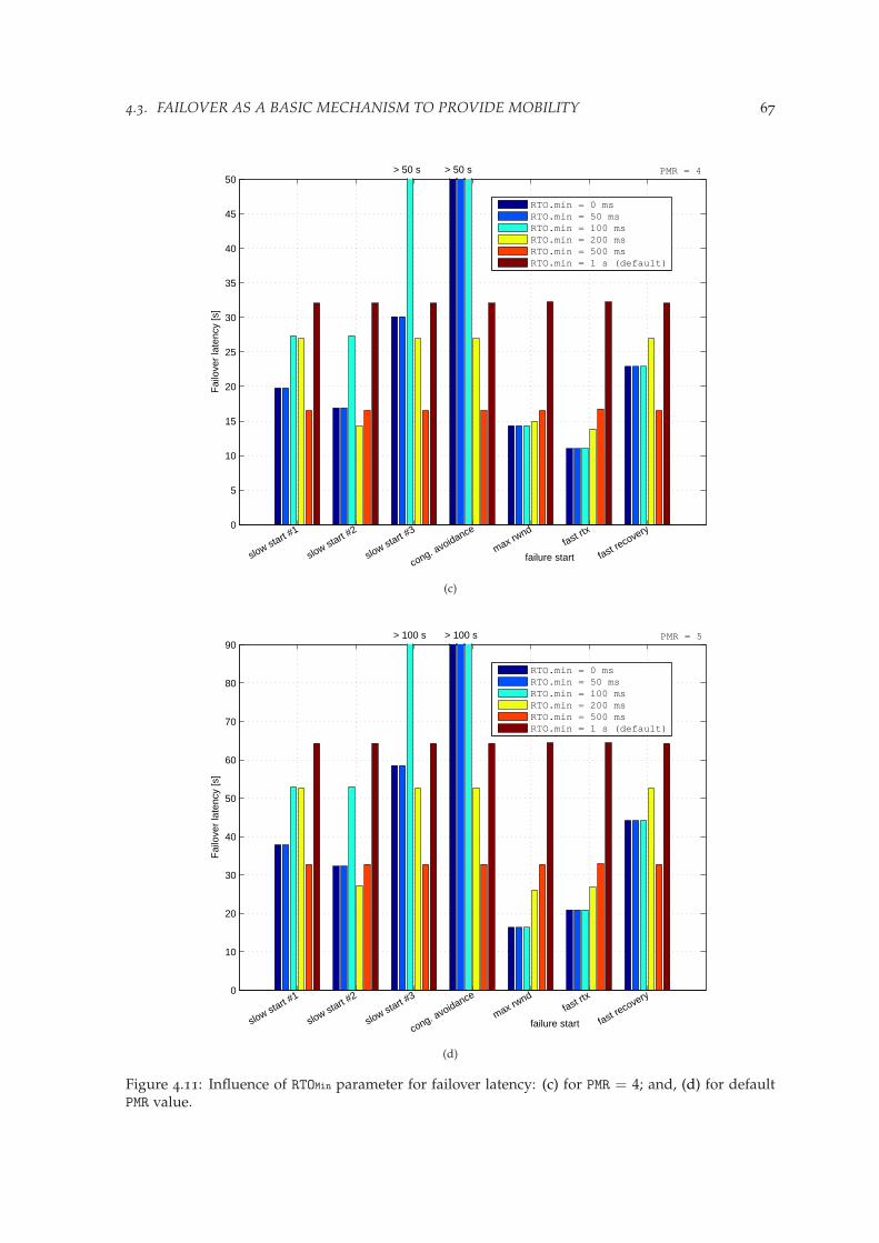
4.3. FAILOVER AS A BASIC MECHANISM TO PROVIDE MOBILITY 67
0
5
10
15
20
25
30
35
40
45
50
Fai
love
r la
tenc
y [s
]
failure startslow start #1
slow start #2
slow start #3
cong. avoidance
max rwnd
fast rtx
fast recovery
PMR = 4
RTO.min = 0 msRTO.min = 50 msRTO.min = 100 msRTO.min = 200 msRTO.min = 500 msRTO.min = 1 s (default)
> 50 s> 50 s
(c)
0
10
20
30
40
50
60
70
80
90
Fai
love
r la
tenc
y [s
]
failure startslow start #1
slow start #2
slow start #3
cong. avoidance
max rwnd
fast rtx
fast recovery
PMR = 5
RTO.min = 0 msRTO.min = 50 msRTO.min = 100 msRTO.min = 200 msRTO.min = 500 msRTO.min = 1 s (default)
> 100 s> 100 s
(d)
Figure 4.11: Influence of RTOMin parameter for failover latency: (c) for PMR = 4; and, (d) for defaultPMR value.

68 CHAPTER 4. FAILOVER AS A BASIC HANDOVER SCHEME
increasing possibility of spurious failovers. The gain produced from decreasing the RTOMin settingis rather evident also for the biggest PMR values (Fig. 4.11c and Fig. 4.11d). With no risk of spuriousfailovers the failover latency can be decreased to only 25% (in the best case) of the value for thedefault PMR setting. Still, among all analyzed cwnd cases the RTOMin set to 500 ms is the lowest valuethat guarantees stable improvement. Below that value two out of seven examined cwnd settingsresulted in unstable performance.
SACK delay
Following its ancestor TCP, SCTP has also the delayed SACK algorithm, designed in line with theguidelines drawn by the RFC2581 [Paxon et al., 1999]. According to that document, resuming TCPcongestion control state of the art as for late 1990s, the SACKs should be generated at least everysecond packet received and at most 500 ms from the arrival of the first unacknowledged packet(so called SACK delay). SCTP specification suggests 200 ms SACK delay to report unacknowledgeddata, leaving room for being more conservative, but not beyond the 500 ms TCP limit. On theother hand there is no space within the protocol specification for more aggressive behavior. Inthat sense study devoted to evaluate the influence of the SACK delay parameter on the failoverbehavior in signaling transport [Eklund and Brunstrom, 2006] seems quite interesting. Eklundand Brunstrom check the failover performance for SACK delay values below 200 ms and concludethat indeed for managed signaling telephony networks having no SACK delay at all may improvefailover performance considering even the cost of introduced traffic overhead. However, in handovercontext possible gain from decreasing SACK delay is rather uncertain, bearing in mind an extraoverhead traffic produced.
Presented set of experiments devoted to analyze the SACK delay parameter (Fig. 4.12) follows theapproach proposed by Eklund and Brunstrom, and takes into account all range of values from nothaving the SACK delay at all, to the biggest value allowed by the protocol specification. Comparedto the default setting (200 ms) there is no significant gain for any of the two lowest PMR values, if theSACK delay value is decreased or even removed at all. The same trend is followed for the defaultPMR setting, the maximum gain reported did not exceed 2%. Therefore, the default value of 200 mscan be clearly preserved, as not harming the protocol performance in the handover context.
HBInt
Another issue that has to be taken into account while discussing the use of failover for handoverscenarios is the heartbeat mechanism. Heartbeat chunks are periodically sent on the idle pathsregardless of the link status (whether is marked as ACTIVE or INACTIVE), within the HBperiod thatis calculated according to the formula (4.15). A tuned heartbeat mechanism may serve for fasterprovisioning of the link state information to the endpoint and as a result induce the failover to a newlink. Heartbeat mechanism also prevents from switching to the paths that are already unavailable.
HBperiod = HBInt + (RTOdest ± 50%RTOdest jitter) (4.15)
The key parameter governing the heartbeat timer is the HBInt that for the default setting excludesusing heartbeat mechanism to probe highly variable wireless scenarios. In order to effectively usethe heartbeat mechanism in the handover scenarios the value of the HBInt should be decreasedsignificantly. However, this adjustment must be made carefully enough in order to avoid introduc-ing too much overhead related to the heartbeat traffic. An example study [Kashihara et al., 2004]shows design of an algorithm based on more frequent heartbeat probing of wireless links. In thatwork Kashihara et al. also propose modifications to PMR settings and the error counting algorithmof a standard SCTP in order to provide support for seamless handover using SCTP and the DARextension.
In this work the idea of modifying the HBInt parameter will be discussed with more detailsduring the design of a SCTP-based handover scheme with CMT support in Section 5.3.2.
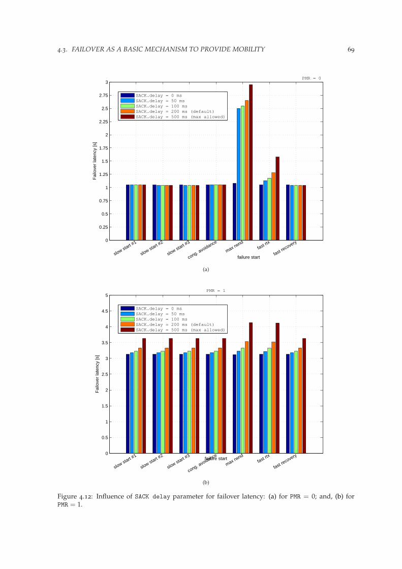
4.3. FAILOVER AS A BASIC MECHANISM TO PROVIDE MOBILITY 69
0
0.25
0.5
0.75
1
1.25
1.5
1.75
2
2.25
2.5
2.75
3
Fai
love
r la
tenc
y [s
]
failure startslow start #
1
slow start #2
slow start #3
cong. avoidance
max rwnd
fast rtx
fast recovery
PMR = 0
SACK.delay = 0 msSACK.delay = 50 msSACK.delay = 100 msSACK.delay = 200 ms (default)SACK.delay = 500 ms (max allowed)
(a)
0
0.5
1
1.5
2
2.5
3
3.5
4
4.5
5
Fai
love
r la
tenc
y [s
]
failure start
slow start #1
slow start #2
slow start #3
cong. avoidance
max rwnd
fast rtx
fast recovery
PMR = 1
SACK.delay = 0 msSACK.delay = 50 msSACK.delay = 100 msSACK.delay = 200 ms (default)SACK.delay = 500 ms (max allowed)
(b)
Figure 4.12: Influence of SACK delay parameter for failover latency: (a) for PMR = 0; and, (b) forPMR = 1.

70 CHAPTER 4. FAILOVER AS A BASIC HANDOVER SCHEME
30
30.5
31
31.5
32
32.5
33
33.5
34
34.5
35F
ailo
ver
late
ncy
[s]
failure startslow start #1
slow start #2
slow start #3
cong. avoidance
max rwnd
fast rtx
fast recovery
PMR = 4
SACK.delay = 0 msSACK.delay = 50 msSACK.delay = 100 msSACK.delay = 200 ms (default)SACK.delay = 500 ms (max allowed)
(c)
62.5
63
63.5
64
64.5
65
65.5
66
66.5
67
67.5
Fai
love
r la
tenc
y [s
]
failure startslow start #1
slow start #2
slow start #3
cong. avoidance
max rwnd
fast rtx
fast recovery
PMR = 5
SACK.delay = 0 msSACK.delay = 50 msSACK.delay = 100 msSACK.delay = 200 ms (default)SACK.delay = 500 ms (max allowed)
(d)
Figure 4.12: Influence of SACK delay parameter for failover latency: (c) for PMR = 4; and, (d) fordefault PMR value.

4.3. FAILOVER AS A BASIC MECHANISM TO PROVIDE MOBILITY 71
Retransmission policy
Within current protocol specification [Stewart, 2007] there is a clear indication of the recommendedretransmission policy (Fast Rtx is handled at the same path and Timeout Rtx is sent to the alternatepath if the peer is multihomed - FRSameToRAlt) that determines the protocol behavior when a per-manent failure occurs and therefore influences the handover latency if the basic failover mechanismis used. However, to gain some insight on the retransmission policy issue it is necessary to men-tion related work conducted by Caro [2005] that discusses pros and cons of various retransmissionpolicies and their impact on failover. In his work Caro reconfirms that the existing FRSameToRAltpolicy is the most universal one for various types of networks considered. On the same time Carorecommends interesting extensions that are namely: Multiple FastRtx (MFR), Heartbeat after RTO(HAR), and Time Stamp (TS). Especially the first extension used in combination with the currentpolicy results in significant improvements to the overall protocol performance and may have impacton the SCTP performance in handover scenarios. However, as this issue is not directly related tothe handover process and still has not been reflected in the protocol specification, it will not bediscussed here in more details.
Recommended parameter settings
To conclude the presented discussion a revised version of SCTP parameter set is provided in Ta-ble 4.3. Such indication serves as a road map for further failover evaluation.
4.3.2 Performance evaluation
Once the framework for SCTP parameters has been established, a detailed failover evaluation canbe given presenting a series of simulation experiments conducted in ns-2 [NS-2]. Presented simula-tions introduce a dynamically changing wireless channel. In contrast to most performance analysispublished so far, such as [Caro, 2005], conditions established at the beginning of the simulation (i.e.,bandwidth, latency and losses) are varying during the entire simulation instance. Such approachhelps to reflect better the variable nature of wireless channels.
Scenario description
Simulation setup for presented experiments reuses the symmetrical scenario topology presentedin Fig. 4.7. Also the same type of application is used, an FTP transfer of a 16 MB file from fixedcorrespondent node to a mobile host. A novelty in presented evaluation is the dynamic channelmodel illustrated in Fig. 4.13.
The dynamic channel model, first presented in [Budzisz et al., 2006a], aims at capturing theprogressive degradation of a radio network interface that finally leads to the link failure, whena threshold value is exceeded. In the simplest approach, this behavior is achieved by means ofvarying PER. The radio conditions move gradually from a steady state, where a minimum PER canbe satisfied, toward another steady state with a higher PER value beyond the threshold that makesthe channel blocked. Parameters describing dynamic channel model on the primary path are, T1,time from transmission start when link starts the transition, and T2, transition time between twosteady states. The counterparts on the backup path, bearing in mind that the backup path becomesavailable with time, are T3 and T4, respectively. The upper limit of the PER values in the channel isset to PERmax; beyond this limit the channel becomes unavailable.
The analysis metrics will take into account the overall effectiveness (average file transfer time),and stability of the transmission (average number of primary path changes). Each experimentis repeated 10 times in order to obtain the average performance (corresponding 95% confidenceintervals were calculated to check the estimate of the underlying average, however in order toimprove the readability of the graphs these results are not included in the plots presented in thischapter). To make the metrics more trustworthy an upper limit of the average transmission time wasset up at 900 seconds (about 68 times the value for the channel without errors). Had the transmissionnot been completed within this time, the sample is discarded, and the average result is calculated
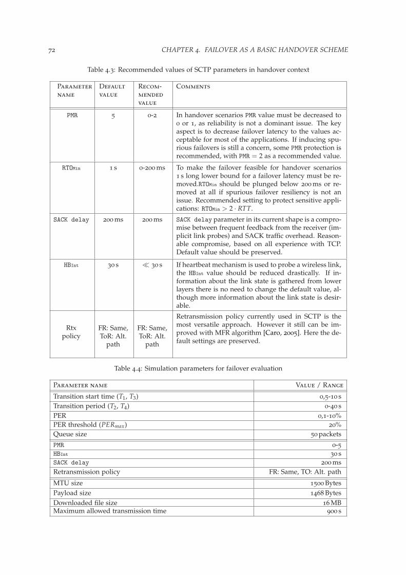
72 CHAPTER 4. FAILOVER AS A BASIC HANDOVER SCHEME
Table 4.3: Recommended values of SCTP parameters in handover context
Parametername
Defaultvalue
Recom-mendedvalue
Comments
PMR 5 0-2 In handover scenarios PMR value must be decreased to0 or 1, as reliability is not a dominant issue. The keyaspect is to decrease failover latency to the values ac-ceptable for most of the applications. If inducing spu-rious failovers is still a concern, some PMR protection isrecommended, with PMR = 2 as a recommended value.
RTOMin 1 s 0-200 ms To make the failover feasible for handover scenarios1 s long lower bound for a failover latency must be re-moved.RTOMin should be plunged below 200 ms or re-moved at all if spurious failover resiliency is not anissue. Recommended setting to protect sensitive appli-cations: RTOMin > 2 · RTT.
SACK delay 200 ms 200 ms SACK delay parameter in its current shape is a compro-mise between frequent feedback from the receiver (im-plicit link probes) and SACK traffic overhead. Reason-able compromise, based on all experience with TCP.Default value should be preserved.
HBInt 30 s ¿ 30 s If heartbeat mechanism is used to probe a wireless link,the HBInt value should be reduced drastically. If in-formation about the link state is gathered from lowerlayers there is no need to change the default value, al-though more information about the link state is desir-able.
Rtxpolicy
FR: Same,ToR: Alt.
path
FR: Same,ToR: Alt.
path
Retransmission policy currently used in SCTP is themost versatile approach. However it still can be im-proved with MFR algorithm [Caro, 2005]. Here the de-fault settings are preserved.
Table 4.4: Simulation parameters for failover evaluation
Parameter name Value / Range
Transition start time (T1, T3) 0,5-10 sTransition period (T2, T4) 0-40 sPER 0,1-10%PER threshold (PERmax) 20%Queue size 50 packets
PMR 0-5HBInt 30 sSACK delay 200 msRetransmission policy FR: Same, TO: Alt. path
MTU size 1500 BytesPayload size 1468 BytesDownloaded file size 16 MBMaximum allowed transmission time 900 s
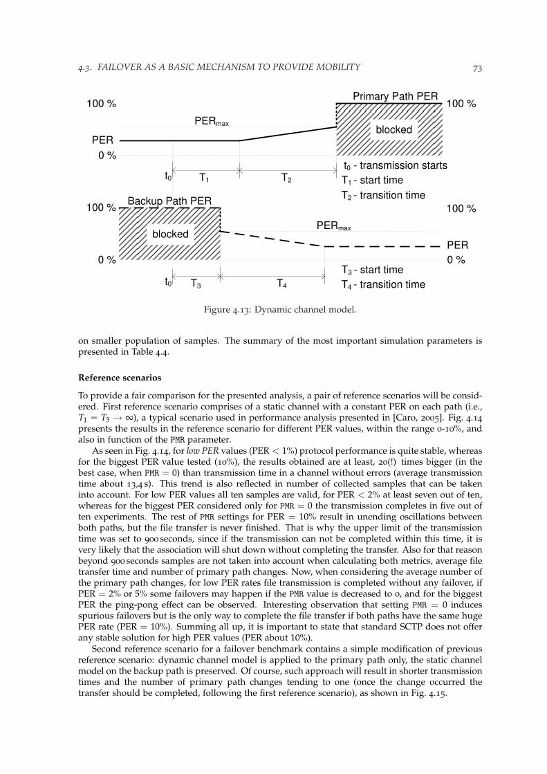
4.3. FAILOVER AS A BASIC MECHANISM TO PROVIDE MOBILITY 73
Backup Path PER
Primary Path PER100 % 100 %
PERmax
T1 - start time
T2 - transition time
T1 T2
PER
0 %
0 %
t0t0 - transmission starts
100 %100 %
PERmax
T3 T4
PER
0 %
t0
T3 - start time
T4 - transition time
blocked
blocked
Figure 4.13: Dynamic channel model.
on smaller population of samples. The summary of the most important simulation parameters ispresented in Table 4.4.
Reference scenarios
To provide a fair comparison for the presented analysis, a pair of reference scenarios will be consid-ered. First reference scenario comprises of a static channel with a constant PER on each path (i.e.,T1 = T3 → ∞), a typical scenario used in performance analysis presented in [Caro, 2005]. Fig. 4.14presents the results in the reference scenario for different PER values, within the range 0-10%, andalso in function of the PMR parameter.
As seen in Fig. 4.14, for low PER values (PER < 1%) protocol performance is quite stable, whereasfor the biggest PER value tested (10%), the results obtained are at least, 20(!) times bigger (in thebest case, when PMR = 0) than transmission time in a channel without errors (average transmissiontime about 13,4 s). This trend is also reflected in number of collected samples that can be takeninto account. For low PER values all ten samples are valid, for PER < 2% at least seven out of ten,whereas for the biggest PER considered only for PMR = 0 the transmission completes in five out often experiments. The rest of PMR settings for PER = 10% result in unending oscillations betweenboth paths, but the file transfer is never finished. That is why the upper limit of the transmissiontime was set to 900 seconds, since if the transmission can not be completed within this time, it isvery likely that the association will shut down without completing the transfer. Also for that reasonbeyond 900 seconds samples are not taken into account when calculating both metrics, average filetransfer time and number of primary path changes. Now, when considering the average number ofthe primary path changes, for low PER rates file transmission is completed without any failover, ifPER = 2% or 5% some failovers may happen if the PMR value is decreased to 0, and for the biggestPER the ping-pong effect can be observed. Interesting observation that setting PMR = 0 inducesspurious failovers but is the only way to complete the file transfer if both paths have the same hugePER rate (PER = 10%). Summing all up, it is important to state that standard SCTP does not offerany stable solution for high PER values (PER about 10%).
Second reference scenario for a failover benchmark contains a simple modification of previousreference scenario: dynamic channel model is applied to the primary path only, the static channelmodel on the backup path is preserved. Of course, such approach will result in shorter transmissiontimes and the number of primary path changes tending to one (once the change occurred thetransfer should be completed, following the first reference scenario), as shown in Fig. 4.15.
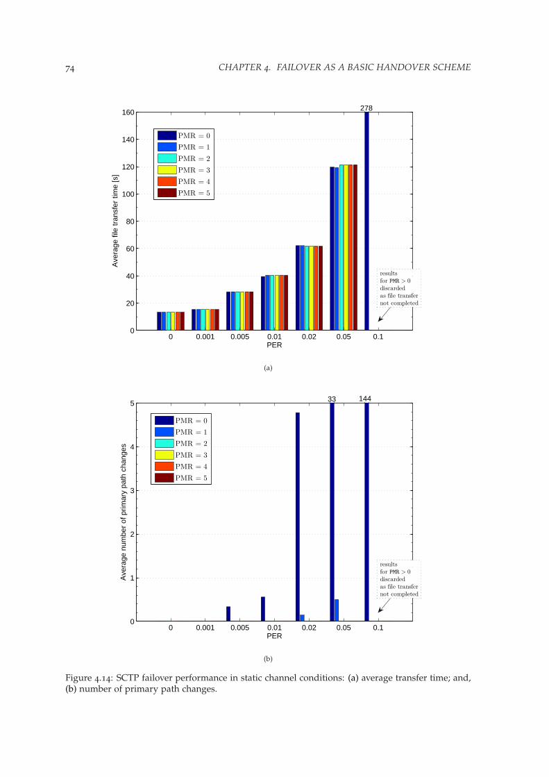
74 CHAPTER 4. FAILOVER AS A BASIC HANDOVER SCHEME
0 0.001 0.005 0.01 0.02 0.05 0.10
20
40
60
80
100
120
140
160
PER
Ave
rage
file
tran
sfer
tim
e [s
]
PMR = 0
PMR = 1
PMR = 2
PMR = 3
PMR = 4
PMR = 5
278
results
for PMR > 0
discarded
as file transfer
not completed
(a)
0 0.001 0.005 0.01 0.02 0.05 0.10
1
2
3
4
5
PER
Ave
rage
num
ber
of p
rimar
y pa
th c
hang
es
PMR = 0
PMR = 1
PMR = 2
PMR = 3
PMR = 4
PMR = 5
33 144
results
for PMR > 0
discarded
as file transfer
not completed
(b)
Figure 4.14: SCTP failover performance in static channel conditions: (a) average transfer time; and,(b) number of primary path changes.

4.3. FAILOVER AS A BASIC MECHANISM TO PROVIDE MOBILITY 75
0.001 0.005 0.01 0.02 0.05 0.10
50
100
150
200
250
PER
Ave
rage
file
tran
sfer
tim
e [s
]
PMR = 0
PMR = 1
PMR = 2
PMR = 3
PMR = 4
PMR = 5
492433408
results
for PMR < 3
discarded
as file transfer
not completed
results
for PMR = 0
discarded
as file transfer
not completed
(a)
0.001 0.005 0.01 0.02 0.05 0.10
0.5
1
1.5
2
2.5
3
PER
Ave
rage
num
ber
of p
rimar
y pa
th c
hang
es
PMR = 0
PMR = 1
PMR = 2
PMR = 3
PMR = 4
PMR = 5
results
for PMR < 3
discarded
as file transfer
not completed
results
for PMR = 0
discarded
as file transfer
not completed
(b)
Figure 4.15: SCTP failover performance in a scenario with deteriorating primary path and staticchannel conditions on the backup path: (a) average transfer time; and, (b) number of primary pathchanges.

76 CHAPTER 4. FAILOVER AS A BASIC HANDOVER SCHEME
Again, the most important tendency that can be observed in Fig. 4.15 is that for low PER ratesthe standard SCTP failover mechanism performs stable, also if the default PMR value is decreased to0 in order to achieve faster file transmission. The channel model used on the primary path forcesthe failover, so that the transmission times from the first scenario can be challenged only if lowPMR settings are used. Not surprisingly, even for the lowest PER rate tested, setting PMR = 0 resultsin 18 second long transmission, PMR = 2 yields already 31 s, but the default PMR beats them all with87 s (most of that spent on a failover), almost seven times longer than the first reference scenario(without failover). Further on, as the PER value increases to 2%, stable transmission is guaranteedby the PMR value not lower than 1 (all ten samples for PMR = 0 were discarded), whereas for thebiggest tested PER rate (10%) PMR = 3 was the lowest value that allowed successful file transmissionin less than 900 seconds. Unlike the first scenario were for PER = 10% all cases but PMR = 0 resultedin unending oscillations between two highly loss paths, having only one path active (the dynamicchannel model blocked the primary path after T1 + T2 from transmission start) led to successfulfile transfer if there was enough retransmissions at the transport layer (PMR ≥ 3). As expected, insuch deterministic scenario only PMR = 0 could lead to increment of the number of average primarypath changes above one, still significantly limited by the PER influence PER < 2%. Concluding,a clear trade-off between transmission time and stability can be drawn here. Comparing protocolperformance to the first reference scenario, the lower values of PMRare excluded, as unstable forbigger PER values.
Results
Now, the proper part of the analysis can be started. The results obtained if the dynamic channelmodel is applied on both paths will be compared with the reference scenarios. For this case, theimportant point to expose is how the previously discussed results change, depending on when thebackup channel becomes available. As seen in Fig. 4.16, the trend for stable performances for lowPER rates, no matter how low is the PMR value, is maintained if dynamically changing channelis applied on both paths. Should the PER value increase, a similar trend as for second referencescenario is observed. Stable transmission threshold is set at PMR = 1 and at PMR = 3 for PER = 2%and PER = 10%, respectively. The trade-off is paid with the transmission time that even for thelowest PER value tested (PER = 0.1%) is at least four times longer(57 s) than in first referencescenario. Interesting from stability point of view that for PER < 2% the transfer time not variesmuch within three lowest values of the PMR.
Comparing to the first reference scenario, proposed channel model excludes low PMR settings(i.e., PMR < 3), as unstable for the biggest PER values tested (PER > 5%). Yet as a result, thenumber of primary changes is also reduced to one for all cases but PMR = 0, as can be seen atFig. 4.16, a similar trend as in second reference scenario. In contrast, for PMR = 0 presented scenarioallows more oscillations (on average 15-17 primary path changes for the three lowest PER rates),as both paths have the dynamic channel model, and active status is maintained longer, but againonly within the low PER values. The number of collected samples is also comparable to the secondscenario, having at least seven out of ten probes for low PER values, and only four for the biggestPER rate.
Influence of link-layer retransmissions
In noisy wireless environments, since SCTP preserves the TCP’s congestion control rules, it is ex-posed to encounter a lot of non-congestion losses that can provoke unnecessary congestion windowreduction at the source. The most common solution to correct errors at the wireless link whilepreserving the transport protocol end-to-end semantic is a combination of FEC (Forward ErrorCorrection) and ARQ (Automatic Repeat Request) [Chockalingam et al., 1999; Vacirca et al., 2006].FEC consumes some extra bandwidth to transport the redundant information that helps recoveringerrors, however does not interfere with transport layer parameters such as round-trip time and re-transmission timeout. Since FEC is not the scope of this analysis, it is assumed that PER parameterreferred in the channel model already includes the effect of FEC corrections. On the other handARQ, used to repeat the packets that FEC is unable to recover, does not consume much bandwidth,
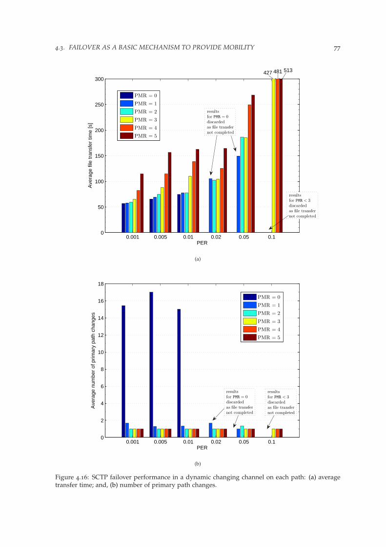
4.3. FAILOVER AS A BASIC MECHANISM TO PROVIDE MOBILITY 77
0.001 0.005 0.01 0.02 0.05 0.10
50
100
150
200
250
300
PER
Ave
rage
file
tran
sfer
tim
e [s
]
PMR = 0
PMR = 1
PMR = 2
PMR = 3
PMR = 4
PMR = 5
513481427
results
for PMR < 3
discarded
as file transfer
not completed
results
for PMR = 0
discarded
as file transfer
not completed
(a)
0.001 0.005 0.01 0.02 0.05 0.10
2
4
6
8
10
12
14
16
18
PER
Ave
rage
num
ber
of p
rimar
y pa
th c
hang
es
PMR = 0
PMR = 1
PMR = 2
PMR = 3
PMR = 4
PMR = 5
results
for PMR < 3
discarded
as file transfer
not completed
results
for PMR = 0
discarded
as file transfer
not completed
(b)
Figure 4.16: SCTP failover performance in a dynamic changing channel on each path: (a) averagetransfer time; and, (b) number of primary path changes.
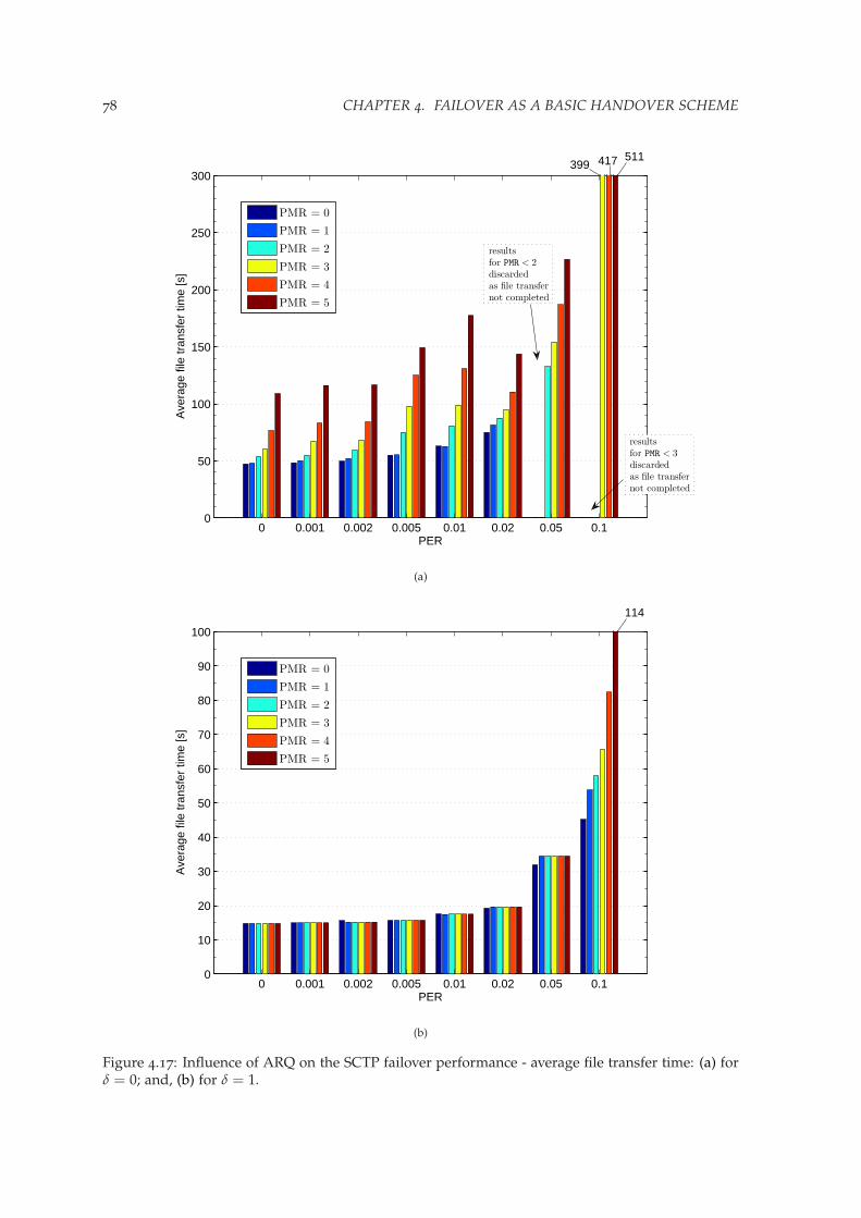
78 CHAPTER 4. FAILOVER AS A BASIC HANDOVER SCHEME
0 0.001 0.002 0.005 0.01 0.02 0.05 0.10
50
100
150
200
250
300
PER
Ave
rage
file
tran
sfer
tim
e [s
]
PMR = 0
PMR = 1
PMR = 2
PMR = 3
PMR = 4
PMR = 5
511417399
results
for PMR < 3
discarded
as file transfer
not completed
results
for PMR < 2
discarded
as file transfer
not completed
(a)
0 0.001 0.002 0.005 0.01 0.02 0.05 0.10
10
20
30
40
50
60
70
80
90
100
PER
Ave
rage
file
tran
sfer
tim
e [s
]
PMR = 0
PMR = 1
PMR = 2
PMR = 3
PMR = 4
PMR = 5
114
(b)
Figure 4.17: Influence of ARQ on the SCTP failover performance - average file transfer time: (a) forδ = 0; and, (b) for δ = 1.

4.3. FAILOVER AS A BASIC MECHANISM TO PROVIDE MOBILITY 79
0 0.001 0.002 0.005 0.01 0.02 0.05 0.113.4
13.6
13.8
14
14.2
14.4
14.6
PER
Ave
rage
file
tran
sfer
tim
e [s
]
PMR = 0
PMR = 1
PMR = 2
PMR = 3
PMR = 4
PMR = 5
(c)
Figure 4.17: Influence of ARQ on the SCTP failover performance - average file transfer time: (c) forδ = ∞.
but indeed may affect SCTP performance in terms of increasing and variable round-trip time (thusdecreasing the throughput) and interfering with timeout, while retransmitting corrupted packets.
Therefore, to extend the scope of presented analysis, the influence of the ARQ on the SCTPfailover performance will be evaluated, following the study [Budzisz et al., 2006b]. The key param-eter here is the number of retransmissions allowed at the link-layer, called the persistence of the ARQ(δ). Consequently, three different cases are considered:
• δ = 0 - no link-layer retransmissions allowed. All the impact of the fluctuating channelconditions goes directly to the transport layer, reducing the available congestion window.
• Finite δ > 0 - channel with losses, shielded at the link-layer, with varying delay. Packettransmission delay is affected by the number of retransmissions. Packet losses are still possibleif reaching a number of retransmissions equal to delta.
• δ = ∞ - channel without losses with varying delay. Long link-layer retransmissions mayprovoke spurious retransmissions on the transport layer, or even timeouts.
First, in Fig. 4.17, the results for the three mentioned channel types are presented: channel notshielded at the link layer (δ = 0), channel shielded with losses (δ = 1), and channel without losses(δ = ∞), accordingly.
Following the TCP’s experience with noisy radio channels, channel not protected at the link layerleads to weak SCTP performance as well, forcing transmission times 400-500 second-long (depend-ing on PMR setting) for the highest 10% PER rate (well more than 30 times longer than in channelwithout errors - 13,4 s), and about 55-120 s for the lowest PER rate investigated 0,1% (4-9 times big-ger than error-free transmission, respectively). Introducing any shielding at the link layer improves

80 CHAPTER 4. FAILOVER AS A BASIC HANDOVER SCHEME
significantly the overall SCTP performance, leading finally to a very stable and fast performance,when many retransmissions are allowed. Here are the examples. With as little as one link-layer re-transmission the transmission time is reduced below 20 seconds for all PER < 5%, and the numberof the collected samples increases to at least nine out of ten for all PER values tested. More, ideallyshielded channel has the transmission time for the biggest PER rate tested only 8% longer than thetransmission without losses (also no failover is forced), and of course, all ten samples collected.
Shielding on the link layer is also visible in terms of number of the primary path changespresented in the Fig. 4.18. In a non-shielded wireless channel, when the entire impact of non-congestion losses goes directly to the transport layer, PMR parameter plays the role of the stabilizingfactor. For PER < 2% it is possible to obtain fairly high throughput rates decreasing the PMR valuefrom the default 5 down to 1. PMR set to 0 even for low PER rates provokes ping-pong effect andthe gain in throughput is not that significant, as if compared to the PMR = 1. Further on, as the PERvalue increases beyond 2%, only higher PMR values guarantee stable file transmission, however as itwas mentioned above the trade-off results in fairly long transmission time, because of exponentialback-off mechanism that triggers handover. Meanwhile, with low PMR values (PMR < 2) file transfercannot be completed within 900 seconds time in a non-shielded channel. For partially shieldedchannel (δ = 1), also the lower PMR values can result in successful file transmission, even if the PERachieves rates as high as 10%. That practically guarantees reliable and fast file transmission. Asfor channel without losses (δ = ∞), all the impact of varying radio channel is handled on the linklayer, and therefore preventing from forcing any failover at the transport layer. Such policy however,could result in spurious retransmissions or even timeouts for very noisy channels. Nevertheless,in the analyzed case, the highest PER rate taken into account 10% (that corresponds to PER ratesvarying between 10 and 20% in the proposed channel model) was not big enough to provoke that.
4.4 Conclusions
SCTP failover mechanism can be reused to grant handover support. The main goal of the analysispresented in this chapter was to provide the quantitative response to that issue, as several doubtswere raised in beforehand. At least a pair of them is of merit. First, as it was rather evident themost of the congestion control rules that were inherited from TCP had negative effect on SCTPperformance in wireless scenarios, in presence of non-congestion losses. Second concern was theSCTP design goal that forced signaling tune-up of protocol parameters. However, once the appro-priate adjustments were made, either by introducing FEC-ARQ shielding at the link-layer of thewireless link or directly to the protocol parameters (see Tab. 4.3), the performance analysis couldgive the response to the main question, whether SCTP failover mechanism is suitable for handoverprovisioning or not. Experiments present clearly that even after tune-up of the most importantprotocol parameters, namely PMR and RTOMin, SCTP failover mechanism is rather unsuitable for real-time applications. On the other hand, non real-time applications have not ruled out completelythe SCTP failover mechanism. In fact, provided that few-second handover latencies are acceptable,experiments suggest that the SCTP failover mechanism could indeed be used for these applications,after necessary PMR and RTOMin parameter adjustments. Yet, as will become evident in the followingsections, there are still better ways of using SCTP for handover than using the failover mechanism.
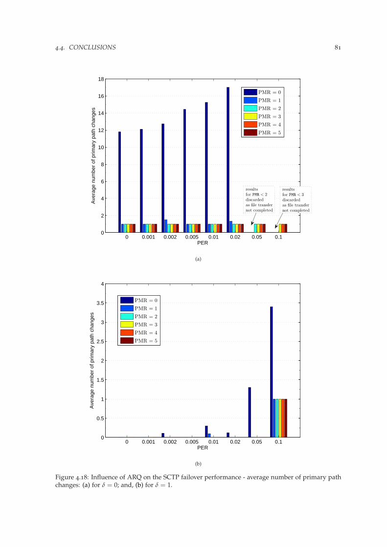
4.4. CONCLUSIONS 81
0 0.001 0.002 0.005 0.01 0.02 0.05 0.10
2
4
6
8
10
12
14
16
18
PER
Ave
rage
num
ber
of p
rimar
y pa
th c
hang
es
PMR = 0
PMR = 1
PMR = 2
PMR = 3
PMR = 4
PMR = 5
results
for PMR < 3
discarded
as file transfer
not completed
results
for PMR < 2
discarded
as file transfer
not completed
(a)
0 0.001 0.002 0.005 0.01 0.02 0.05 0.10
0.5
1
1.5
2
2.5
3
3.5
4
PER
Ave
rage
num
ber
of p
rimar
y pa
th c
hang
es
PMR = 0
PMR = 1
PMR = 2
PMR = 3
PMR = 4
PMR = 5
(b)
Figure 4.18: Influence of ARQ on the SCTP failover performance - average number of primary pathchanges: (a) for δ = 0; and, (b) for δ = 1.

82 CHAPTER 4. FAILOVER AS A BASIC HANDOVER SCHEME

Chapter 5
Improving handover withtransport-layer loadsharing
Transport-layer loadsharing is another application that extends the use of SCTP multihoming, relativeto what is defined within the standard protocol specification. If compared to loadsharing schemesin other layers [Goff and Phatak, 2004], transport-layer loadsharing has a considerable potential toimprove protocol performance (in terms of overall throughput) and provide an useful solution fromthe application point of view. The major challenge arising from simultaneous data transfer overmultiple paths is packet reordering at the receiver. This issue may deteriorate SCTP performance,since congestion control algorithms in standard SCTP are derived from TCP, and hence do not workwell when reordering is common. Congestion control in standard SCTP is applied to the entireassociation (i.e., as an inheritance from TCP, a unique TSN numeration is used for all destinations),however separate sets of congestion control variables (cwnd, sstresh and partial bytes acked) arekept for each of the destination addresses of a multihomed peer. Thus, to accomplish loadsharingthe SCTP send-buffer management and congestion control must be updated to take into accountthe problems of sending data over multiple paths using a single sequence-number space, and theconsequences of sender-introduced reordering. So far, there is no commonly defined extension thatfacilitates loadsharing for SCTP. Therefore, the most important proposals will be examined herein detail. Then, the applicability of the most common solution (Concurrent Multipath Transfer) todistribute data among two end-to-end paths of a mSCTP association during the handover transitionprocess will be evaluated. To that end, the design principles of a protocol extension that joinsConcurrent Multipath Transfer and mSCTP are given. The proposed new handover scheme isbenchmarked with pure mSCTP handover scheme, demonstrating its potential benefits: smoothingthe handover transition process, and improving the application’s overall throughput.
5.1 Related work on transport-layer loadsharing with SCTP
One of the first proposals for loadsharing with SCTP, called LS-SCTP has been brought up by AbdEl Al et al. [2004a,b]. LS-SCTP separates flow control, handled per association, from congestioncontrol that for loadsharing need to be handled per path. Therefore, Abd El Al et al. propose intro-duction of two additional chunk types to carry data and related acknowledgment in LS-SCTP. Bothchunks are backward-compatible with corresponding standard SCTP chunks, the only differencebeing the additional sequence numbers added to facilitate the loadsharing congestion control. Theproposed solution offers also a modified path monitoring mechanism, with more frequent heartbeatprobing, to avoid stalling the application on an inactive path. The additional per path numberingintroduced by LS-SCTP results in an unnecessary overhead as similar information can be inferredfrom the sender state variables and SACK chunks in their standard shape. This is the approach ofanother loadsharing proposal, called independent per path congestion control SCTP (IPCC-SCTP)introduced by Ye et al. [2004]. IPCC-SCTP, instead of using explicit per path numbering (as in caseof LS-SCTP), provides local, per path mapping for each SCTP packet. This information is necessary
84 CHAPTER 5. IMPROVING HANDOVER WITH TRANSPORT-LAYER LOADSHARING
only at the sender-side to control the congestion, thus sending of redundant information is avoided.Thanks to this local mapping, IPCC-SCTP can govern congestion control, SACK processing, and re-transmission handling on each path separately, instead of doing it for the entire association (whenusing just TSN information) as in standard SCTP.
5.1.1 Concurrent multipath transfer
IPCC-SCTP’s implicit per path sequence numbering approach has been followed in the design ofthe most common loadsharing scheme so far, Concurrent Multipath Transfer (CMT), fully describedin [Iyengar et al., 2006]. The idea of CMT was first introduced in [Iyengar et al., 2004a], however incontrast to IPCC-SCTP, CMT has been further developed in the following years. To accommodateCMT, Iyengar et al. propose a new sender architecture, where each path has a virtually separatebuffer to guarantee path independence. This modification preserves TCP-friendliness under theassumption that the bottleneck is not shared by the paths.
Of course, such a multibuffer sender structure has its implications on congestion control, andtherefore several changes to standard SCTP must be considered. All algorithms cited here wereproposed and tested in fixed networks by Iyengar et al. [2006], and in their current shape will beincorporated to wireless scenarios in the analysis presented in Section 5.2:
1. To handle congestion control per-path, not per association, a sender cwnd growth algorithm(cwnd update for CMT - CUC) has been proposed. Thus, SACKs updating the CumTSNreceived in-order per path and out-of-order per association increase the cwnd on that path.
2. Fast retransmission needs slight modification as reordering introduced on the sender sidecan provoke unnecessary spurious fast retransmissions with cwnd implications. Eliminationof spurious fast retransmissions is handled by the Split Fast Retransmit (SFR) algorithm thattakes into account not only SACK information, but also transmission destination for eachTSN when triggering the retransmission to a given path. The missing report counter isincreased only at the destination where considered TSN was sent.
3. The CMT receiver should not send immediate SACKs irrespectively of whether arrivingpacket has been received in order or not, as networks may be vulnerable for the increasedACK traffic. As the SCTP receiver does not distinguish loss from reordering introduced bya CMT sender, therefore to correctly infer losses at the sender, an algorithm called DelayedACK for CMT (DAC) was applied. On the receiver side, DAC algorithm adds to SACKinformation about the number of data PDUs received since the last SACK was sent (a flagin chunk header indicates either one or two PDUs received). This information is processedon the sender side, to indicate the SFR algorithm by how many the missing report countershould be increased.
4. CMT requires an appropriate policy to handle retransmissions. This topic has been inves-tigated in more detail in [Iyengar et al., 2004b], with five retransmission policies being pro-posed:
(a) RtxSame - send retransmission to the same path,(b) RtxAsAp - send retransmission to any destination that has cwnd space available,(c) RtxCwnd - path with the highest cwnd is chosen,(d) RtxSsthresh - path with the highest ssthresh is chosen,(e) RtxLossRate - path with the lowest loss rate is chosen; loss rate of each path is known
in advance.According to Iyengar et al. [2004b], the best results for bulk applications were achieved bythe loss rate-based policies, i.e. the policies that either try to estimate the loss rate of eachpath, namely RtxCwnd and RtxSsthresh, or know the loss rate in advance (RtxLossRate).Following this conclusion, and taking into account that cwnd reacts faster than ssthresh tochange of the link conditions, the RtxCwnd policy (path with the highest cwnd handles theretransmission), has been chosen to be used in the experiments presented in this work.
Despite of an extense work spent on its development, CMT can provoke the following problems,which relevance should be assessed when considering handover scenarios:
1. Receiver buffer (rbuf) blocking (receiver buffer is filled with out-of-order data) caused bycomplete or short-term failures. This problem has already been tackled by Iyengar et al.

5.1. RELATED WORK ON TRANSPORT-LAYER LOADSHARING WITH SCTP 85
[2005, 2007] who focused in their work on wired-only scenarios. A solution that partiallymitigates receiver buffer blocking, called CMT Potentially Failed (CMT-PF) has been pro-posed in [Natarajan et al., 2009, 2006]. CMT-PF marks the path that has experienced a failure(single timeout) as potentially failed, and stops transmitting data on such a path, until apositive heartbeat probe is returned. In case the PMR threshold was exceeded (with PMR + 1consecutive failures) the path is marked as inactive (same as in standard SCTP). The PF stateprevents the PMR parameter settings from degrading the throughput performance during fail-ure scenarios, as the exponential backoff mechanism clocks only the HB packets. CMT-PFproposal is dedicated to lossy scenarios, e.g. wireless networks, thus making feasible the ideaof applying CMT to improve transport-layer handover.
2. An ambiguity at the sender for the SACKs with the same CumTSN that acknowledge variousGap ACK blocks: first more Gap ACK blocks are acked on the faster path followed then bya packet with fewer Gap ACK blocks received on the slower path. This can lead to anunnecessary retransmission in case the difference between paths’ bandwidth is high.
3. Incorrect RTT estimate on a slower path that comes from the ambiguity of the SACK receivedon the faster path that also acknowledges the packet marked for a RTT estimation on theslower path.
5.1.2 Scheduling algorithms
Additionally, loadsharing support can be complemented with source scheduling algorithm. Asource scheduling algorithm picks the optimal path for transporting a DATA chunk, estimatingwhich of the available paths is most likely to deliver (deliver first) the DATA to the receiver. Anestimate takes into account current path conditions, e.g., number of outstanding chunks, availablebandwidth, etc. The work by Casetti et al. [2004] provides an initial idea for load balancing basedon a bandwidth-aware source scheduling extension to SCTP. Casetti et al. suggest sending back-to-back a pair of heartbeat packets to estimate the available bandwidth, and picking the fastest path totransmit data, as the simplest approach named Sender-Based Packet-Pair (SBPP) SCTP. This idea isfurther developed with a design of Westwood-like SCTP (W-SCTP) proposed by Fiore and Casetti[2005]; Fiore et al. [2007]. Apart from introducing a multibuffer structure and per-path congestioncontrol, modifications similar to these described for CMT, Fiore and Casetti employ a packet sched-uler that maximizes the chance that packets sent on paths with different bandwidths will arrive inorder at the receiver, thus minimizing the receiver buffer blocking problem. The bandwidth esti-mation is made in a Westwood-like manner, giving the name for the proposed scheme. Moreover,an explicit advance acknowledgment algorithm and a minimum bandwidth estimate threshold areprovided to increase the robustness of the presented approach. An exhaustive comparison of bothapproaches (SBPP and W-SCTP) based on emulation results is provided by Perotto et al. [2007].W-SCTP is also used together with the PR-SCTP extension (the entire scheme is named W-SCTP-PR) to provide support for real-time applications, as presented in [Fiore and Casetti, 2005]. Furtherstudies on multimedia traffic have been conducted by Rossi et al. [2006]. The use of load balancingto support the needs of video applications has also been evaluated by Abd El Al et al. [2007].
5.1.3 Taxonomy
To complement the review of the related work on transport layer loadsharing with SCTP, Fig 5.1presents distribution of the loadsharing-related research over the dimensions of the taxonomy in-troduced by Budzisz et al. [2008], described already in more details in this work in Section 3.2.1.What possibly differs loadsharing from the other two analyzed uses of multihoming (i.e., originallyconsidered robustness and transport layer mobility) is the variety of possible applications (contri-bution is witnessed in each category but Other applications, with the most important applicationbeing bulk transfer) and considerable versatility of analyzed network scenarios (more or less equallydistributed between categories of wired and wireless domain). Again, simulation proves to be themost common study approach, whereas articles based on the emulation results are the second maingroup, with a considerably lower share.
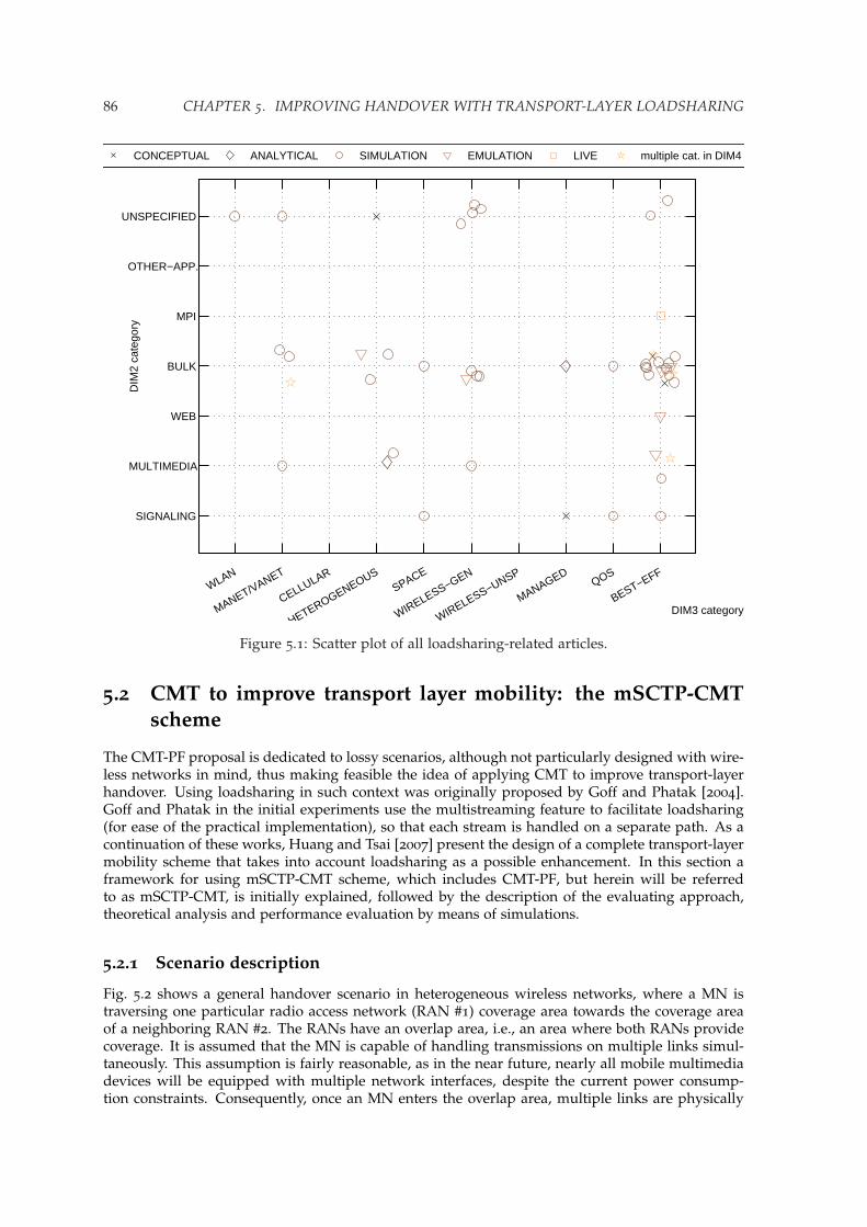
86 CHAPTER 5. IMPROVING HANDOVER WITH TRANSPORT-LAYER LOADSHARING
SIGNALING
MULTIMEDIA
WEB
BULK
MPI
OTHER−APP.
UNSPECIFIED
DIM3 category
DIM
2 ca
tego
ry
WLAN
MANET/VANET
CELLULAR
HETEROGENEOUSSPACE
WIRELESS−GEN
WIRELESS−UNSP
MANAGEDQOS
BEST−EFF
CONCEPTUAL ANALYTICAL SIMULATION EMULATION LIVE multiple cat. in DIM4
Figure 5.1: Scatter plot of all loadsharing-related articles.
5.2 CMT to improve transport layer mobility: the mSCTP-CMTscheme
The CMT-PF proposal is dedicated to lossy scenarios, although not particularly designed with wire-less networks in mind, thus making feasible the idea of applying CMT to improve transport-layerhandover. Using loadsharing in such context was originally proposed by Goff and Phatak [2004].Goff and Phatak in the initial experiments use the multistreaming feature to facilitate loadsharing(for ease of the practical implementation), so that each stream is handled on a separate path. As acontinuation of these works, Huang and Tsai [2007] present the design of a complete transport-layermobility scheme that takes into account loadsharing as a possible enhancement. In this section aframework for using mSCTP-CMT scheme, which includes CMT-PF, but herein will be referredto as mSCTP-CMT, is initially explained, followed by the description of the evaluating approach,theoretical analysis and performance evaluation by means of simulations.
5.2.1 Scenario description
Fig. 5.2 shows a general handover scenario in heterogeneous wireless networks, where a MN istraversing one particular radio access network (RAN #1) coverage area towards the coverage areaof a neighboring RAN #2. The RANs have an overlap area, i.e., an area where both RANs providecoverage. It is assumed that the MN is capable of handling transmissions on multiple links simul-taneously. This assumption is fairly reasonable, as in the near future, nearly all mobile multimediadevices will be equipped with multiple network interfaces, despite the current power consump-tion constraints. Consequently, once an MN enters the overlap area, multiple links are physically

5.2. CMT TO IMPROVE TRANSPORT LAYER MOBILITY: THE MSCTP-CMT SCHEME 87
Correspondent
Node
Intermediate
router
RAN #2
RAN #1
Mobile
Node
Overlap
area
Figure 5.2: Proposed CMT scenario.
available for simultaneous data transmission.It is further assumed that the different paths do not share bottlenecks, i.e., the radio link of each
path is the bottleneck. This is a coherent supposition taking into account the mixed wired-wirelesstopology of the envisaged scenarios, and as it was explained in Section 5.1.1, it is vitally importantfor the use of CMT. As a consequence, the bottlenecks on each path are independent and a sendercan consider a per-path congestion approach, while still preserving overall TCP-friendliness.
Now focusing on the proposed mSCTP-CMT handover scheme, this work considers one direc-tional bulk data flow from a CN to the MN. As presented in Fig. 5.3, a MN configured initially withIP1 address before entering an overlap area is using the mSCTP protocol to transfer data on a singlelink. When the MN enters the overlap area, the coverage of RAN #2 is discovered. To get the newlink operational, the MN undergoes the correspondent network registration procedure. Both thenetwork discovery process and registration procedure details [Honda et al., 2007] are outside thescope of this work. As soon as the network address IP2 in RAN #2 is operational, the CN must beinformed about the new destination (by means of ASCONF chunk), and has to verify its availability(sending HB chunk). Once the new destination is confirmed, the IP2 address is considered availablefor normal data transfer. At this point, CMT can be exploited while having two paths available.Finally, when the MN leaves the overlap area, it is necessary to: (1) quit CMT mode, (2) handle anyretransmissions of packets that were in flight on the link that just went down, and (3) perform allnecessary congestion adjustments on the current path for the once again single-homed MN.
The main goal of this work is to evaluate whether is possible to apply CMT in the presentedhandover scenario, what gains can be achieved, and in which situations, if any, might the use ofCMT degrade service. To this end, the described mSCTP-CMT handover scheme will be comparedto two benchmark schemes:
• a handover based on the optimized failover mechanism of standard SCTP, as illustrated inFig. 3.18c. To optimize for handover scenarios, standard SCTP’s failover mechanism wastailored with low PMR settings and the RTOMin limitation was removed, as described in Sec-
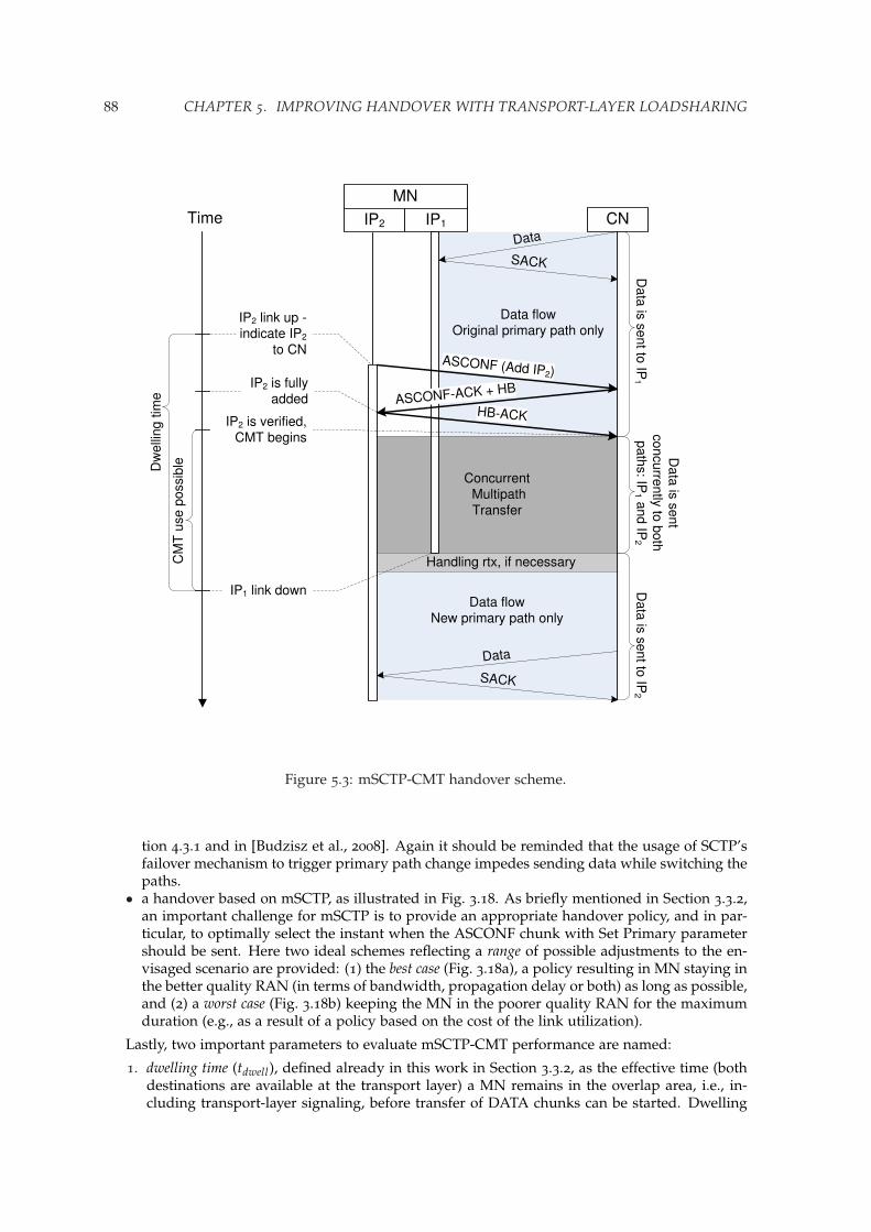
88 CHAPTER 5. IMPROVING HANDOVER WITH TRANSPORT-LAYER LOADSHARING
Data flow
New primary path only
Handling rtx, if necessary
Data flowOriginal primary path only
IP1
Concurrent Multipath
Transfer
IP2
Data
SACK
Data
SACK
ASCONF (Add IP2)
HB-ACKASCONF-ACK + HB
Time
CM
T u
se p
ossib
leDw
elli
ng tim
e
IP2 link up -indicate IP2
to CN
IP2 is fully
added
IP2 is verified,CMT begins
MN
CND
ata
is s
ent to
IP1
Data
is s
ent to
IP2
Data
is s
ent
concurre
ntly
to b
oth
path
s: IP
1and IP
2
IP1 link down
Figure 5.3: mSCTP-CMT handover scheme.
tion 4.3.1 and in [Budzisz et al., 2008]. Again it should be reminded that the usage of SCTP’sfailover mechanism to trigger primary path change impedes sending data while switching thepaths.
• a handover based on mSCTP, as illustrated in Fig. 3.18. As briefly mentioned in Section 3.3.2,an important challenge for mSCTP is to provide an appropriate handover policy, and in par-ticular, to optimally select the instant when the ASCONF chunk with Set Primary parametershould be sent. Here two ideal schemes reflecting a range of possible adjustments to the en-visaged scenario are provided: (1) the best case (Fig. 3.18a), a policy resulting in MN staying inthe better quality RAN (in terms of bandwidth, propagation delay or both) as long as possible,and (2) a worst case (Fig. 3.18b) keeping the MN in the poorer quality RAN for the maximumduration (e.g., as a result of a policy based on the cost of the link utilization).
Lastly, two important parameters to evaluate mSCTP-CMT performance are named:
1. dwelling time (tdwell), defined already in this work in Section 3.3.2, as the effective time (bothdestinations are available at the transport layer) a MN remains in the overlap area, i.e., in-cluding transport-layer signaling, before transfer of DATA chunks can be started. Dwelling

5.2. CMT TO IMPROVE TRANSPORT LAYER MOBILITY: THE MSCTP-CMT SCHEME 89
Table 5.1: Basic simulation parameters
Parameter name Value / Range
Wired part (each path) bandwidth: 100 Mbpsone-way propagation delay: 5 ms
(modified in advanced analysis, Section 5.2.4)fast RAN bandwidth: (bwratio× 384) kbps
one-way propagation delay: 15 msslow RAN bandwidth: 384 kbps
one-way propagation delay: 80 msscenario pattern RAN #1: fast RAN
RAN #2: slow RAN(modified in advanced analysis, Section 5.2.4)
bwratio 1-14dwelling time(in function of bw ratio)
bwratio = 1-2: 2-80 sbwratio = 3-4: 2-40 sbwratio = 6-8: 2-20 sbwratio ≥ 10: 2-10 s
rbuf size 16-256 kB(ideal buffer up to 2 MB)
RTOMin 50 msPMR Optimized failover, mSCTP: 1
CMT: 5SACK delay 200 msRetransmission policies mSCTP FastRtx: Same path
mSCTP TimeoutRtx: Alternate pathCMTRtx: path with largest cwnd
MTU size / Data payload 1500 / 1468 BytesFile size 8 MB (5778 DATA chunks)
time is affected by the speed of the MN, as well as its movement pattern, and therefore maybe crucial for using CMT. Depending on the scenario considered, tdwell can vary in practicefrom a few seconds for fast MNs going across the overlap area to tenths of seconds for slowMNs traversing the overlap area.
2. bandwidth ratio (bwratio), defined as a ratio of the bandwidths available in the neighboringRANs (in this work always the faster bandwidth is related to the slower one, so the bwratio ≥1). bwratio reflects the asymmetry of a handover scenario.
To study the feasibility of mSCTP-CMT for transport-layer handover, a series of simulation ex-periments in ns-2 (ver. 2.32) [NS-2] was conducted, adjusting an existing CMT-PF implementationto work with heterogeneous wireless environments (refer Appendix A.2.1). The most importantsimulation parameters in their basic configuration for various experiments performed in the sce-nario under test (Fig. 5.2) are presented in Table 5.1. More detailed specification of the parametersspecific to a particular test is provided with each set of the experiments. However, before looking forthe simulation results of the mSCTP-CMT in such a defined handover scenario, the maximum pos-sible gain that can be achieved will be estimated, and related to mentioned mSCTP-based handoverschemes.
5.2.2 Analytical model
The proposed scenario under test (Fig. 5.2) considers the following basic mobility pattern: (1) firstthe MN moves within the coverage area of RAN #1 (faster of the two), (2) after t1 from the trans-mission start, the MN enters the overlap area where there is a possibility of applying CMT scheme

90 CHAPTER 5. IMPROVING HANDOVER WITH TRANSPORT-LAYER LOADSHARING
during tdwell , and finally (3) MN leaves the overlap area and remains in RAN #2 (slower RAN),where again only one path is available for data transmission. Then, the minimum time necessaryto transmit a file of size L (given that L is large enough, so that the transmission is not completedbefore leaving the overlap area) depends on the available bandwidth that the MN can achieve ineach of the discussed regions. Hence:
T =3
∑i=1
ti =3
∑i=1
Libwi
=L1
bw1+
Loverlap
bwoverlap+
L2
bw2(5.1)
As can be easily seen from formula (5.1) the main factor differentiating the performance of alldiscussed handover schemes is the bandwidth available in the overlap area (bwoverlap). If CMT isapplied in the analyzed scenario with two paths available for using CMT during the tdwell , thebwoverlap can be estimated as:
bwoverlap ≤ bw1 + bw2 (5.2)
The maximum gain in terms of file transfer time reduction will be produced when the bwoverlapwould be equal to the sum of the values of each link bandwidth, bw1 and bw2, respectively. There-fore, theoretically the minimum time necessary to transmit the entire file of size L when CMT isapplied in the overlap area is:
Tcmt th = t1 + tdwell +L− t1 · bw1 − tdwell · (bw1 + bw2)
bw2
leading to:
Tcmt th = t1 +L
bw2− (t1 + tdwell) · bwratio (5.3)
For mSCTP-based handover schemes the handover policy will influence the value of bwoverlap,changing its value from min (bw1, bw2) (bandwidth of the slower of the two RANs) in the worstcase to max (bw1, bw2) in the best case, during the time the MN stays in the overlap area (tdwell).Therefore, corresponding file transfer times are,
for the mSCTP worst case:
Tmsctp worst = t1 +L
bw2− t1 · bwratio (5.4)
and for the mSCTP best case:
Tmsctp best = t1 + tdwell +L
bw2− (t1 + tdwell) · bwratio (5.5)
Finally, the maximum theoretical gain of mSCTP-CMT over mSCTP schemes (∆T) in terms offile transfer time reduction can be expressed as:
∆T ∈ [∆min, ∆max] =[Tmsctp best − Tcmt th, Tmsctp worst − Tcmt th
]
∆T ∈ [tdwell , tdwell · bwratio] (5.6)
Moreover, equation (5.3) expressing the best theoretical time for the mSCTP-CMT handoverscheme will be used to benchmark the results obtained in the simulations.
5.2.3 Basic performance evaluation
A basic analysis will examine not only (1) the possible gain that can be achieved using mSCTP-CMT handover scheme, as presented in [Budzisz, Ferrus, Casadevall, and Amer, 2009], but also(2) the potential of smoothing the transition process, as well as (3) the influence of dedicated CMTretransmission policies.

5.2. CMT TO IMPROVE TRANSPORT LAYER MOBILITY: THE MSCTP-CMT SCHEME 91
0 20 40 60 80 100 120 140 160 1800
1000
2000
3000
4000
5000
6000
Time [s]
Cum
ulat
ive
TS
N
Single link SCTPOptimized failovermSCTP best casemSCTP worst casemSCTP−CMT with no rbuf blockingmSCTP−CMT rbuf blocking
Range ofpossiblemSCTP
performance
Range ofpossible
mSCTP−CMTperformance
without rbuf blockingmSCTP−CMT performs better than
mSCTP best case
EOF = 5778
(a)
Figure 5.4: Performance comparison of all SCTP versions for bwratio = 4, and tdwell = 40 s: (a) entirefile transfer.
TSN-time evolution
Fig. 5.4 presents a performance comparison in terms of TSN-time evolution diagram for all SCTPprotocol versions described in Section 5.2.1, namely: (1) optimized failover, (2) mSCTP-based solu-tion (both best and worst case), and (3) the mSCTP-CMT scheme (with two different values of rbufsize, 32 kB and 512 kB, to illustrate receiver buffer blocking problem). Additionally, obtained resultsare related to a single link SCTP performance (i.e., considering a hypothetical case where faster ofthe two RANs is available for the complete file transfer). As can be seen in Fig. 5.4b, the overlaparea (2-42 s in the time scale) is the zone of special interest, witnessing different slope values for thepresented SCTP flavors. Nearly all possible mSCTP-CMT gain over pure mSCTP-based handoverschemes will be produced here, if strict constraints on rbuf size are met. The range for possiblemSCTP-CMT performance gain is significant, from being much worse than the best mSCTP policy(almost as bad as the worst one) in presence of rbuf blocking, to gaining over the best mSCTP policy(as well as failover-based scheme and faster of the two links) for an appropriate rbuf size adjust-ment. Still in any of the considered cases mSCTP-CMT did not perform any worse than the worstmSCTP policy. In an effort to identify the application area for mSCTP-CMT, all important factorssuch as, tdwell , bwratio and rbuf size will be analyzed now in more detail.
Dwelling time
As seen in dwelling time graph (Fig. 5.5), users with short tdwell would have no significant gainfrom using mSCTP-CMT when compared to mSCTP-based schemes in any of the presented cases.In contrast, having long tdwell can effectively benefit from mSCTP-CMT. This conclusion followsthe results of theoretical analysis from Section 5.2.2, and so do the respective gains of mSCTP-CMT over both extreme cases of mSCTP (correspondent gains are marked at each graphics). Forbwratio = 2 the supposition made in the theoretical analysis that the file is large enough, so that the
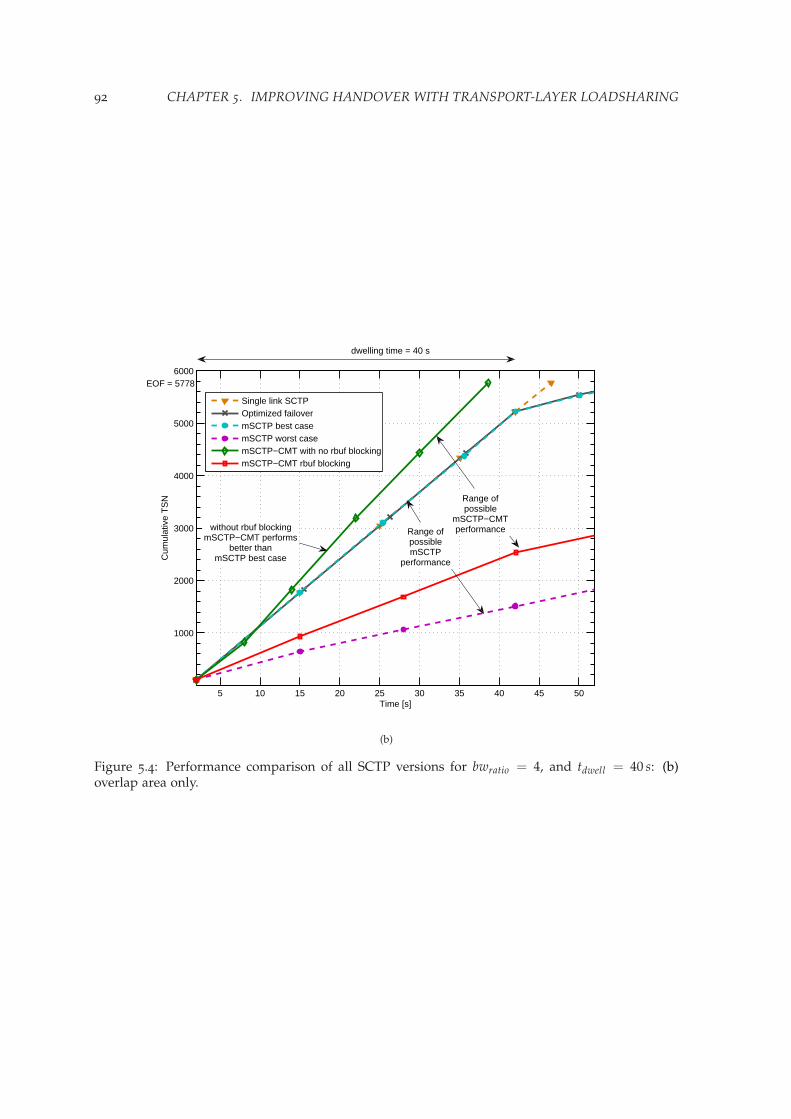
92 CHAPTER 5. IMPROVING HANDOVER WITH TRANSPORT-LAYER LOADSHARING
5 10 15 20 25 30 35 40 45 50
1000
2000
3000
4000
5000
6000
Time [s]
Cum
ulat
ive
TS
N
Single link SCTPOptimized failovermSCTP best casemSCTP worst casemSCTP−CMT with no rbuf blockingmSCTP−CMT rbuf blocking
Range ofpossiblemSCTP
performance
Range ofpossible
mSCTP−CMTperformancewithout rbuf blocking
mSCTP−CMT performsbetter than
mSCTP best case
dwelling time = 40 s
EOF = 5778
(b)
Figure 5.4: Performance comparison of all SCTP versions for bwratio = 4, and tdwell = 40 s: (b)overlap area only.

5.2. CMT TO IMPROVE TRANSPORT LAYER MOBILITY: THE MSCTP-CMT SCHEME 93
0 10 20 30 40 50 60 70 8040
60
80
100
120
140
160
180
dwelling time [s]
File
tran
sfer
tim
e [s
]
bwratio = 2
mSCTP−CMT with rbuf 32kB
mSCTP−CMT with rbuf 128kB
mSCTP−CMT with ideal rbuf
mSCTP best case
mSCTP worst case
analytical model mSCTP−CMT
∆max
∆min
(a)
0 5 10 15 20 25 30 35 400
20
40
60
80
100
120
140
160
180
dwelling time [s]
File
tran
sfer
tim
e [s
]
bwratio = 4
mSCTP−CMT with rbuf 32kB
mSCTP−CMT with rbuf 128kB
mSCTP−CMT with ideal rbuf
mSCTP best case
mSCTP worst case
analytical model mSCTP−CMT
∆max
∆min
(b)
Figure 5.5: Comparison in function of dwelling time for: (a) bwratio = 2; and, (b) bwratio = 4.

94 CHAPTER 5. IMPROVING HANDOVER WITH TRANSPORT-LAYER LOADSHARING
2 4 6 8 10 12 14 16 18 2040
60
80
100
120
140
160
180
dwelling time [s]
File
tran
sfer
tim
e [s
]
bwratio = 6
mSCTP−CMT with rbuf 32kB
mSCTP−CMT with rbuf 128kB
mSCTP−CMT with ideal rbuf
mSCTP best case
mSCTP worst case
analytical model mSCTP−CMT
∆max
∆min
(c)
2 4 6 8 10 12 14 16 18 200
20
40
60
80
100
120
140
160
180
dwelling time [s]
File
tran
sfer
tim
e [s
]
bwratio = 8
mSCTP−CMT with rbuf 32kB
mSCTP−CMT with rbuf 128kB
mSCTP−CMT with ideal rbuf
mSCTP best case
mSCTP worst case
analytical model mSCTP−CMT
∆max
∆min
(d)
Figure 5.5: Comparison in function of dwelling time for: (c) bwratio = 6; and, (d) bwratio = 8.
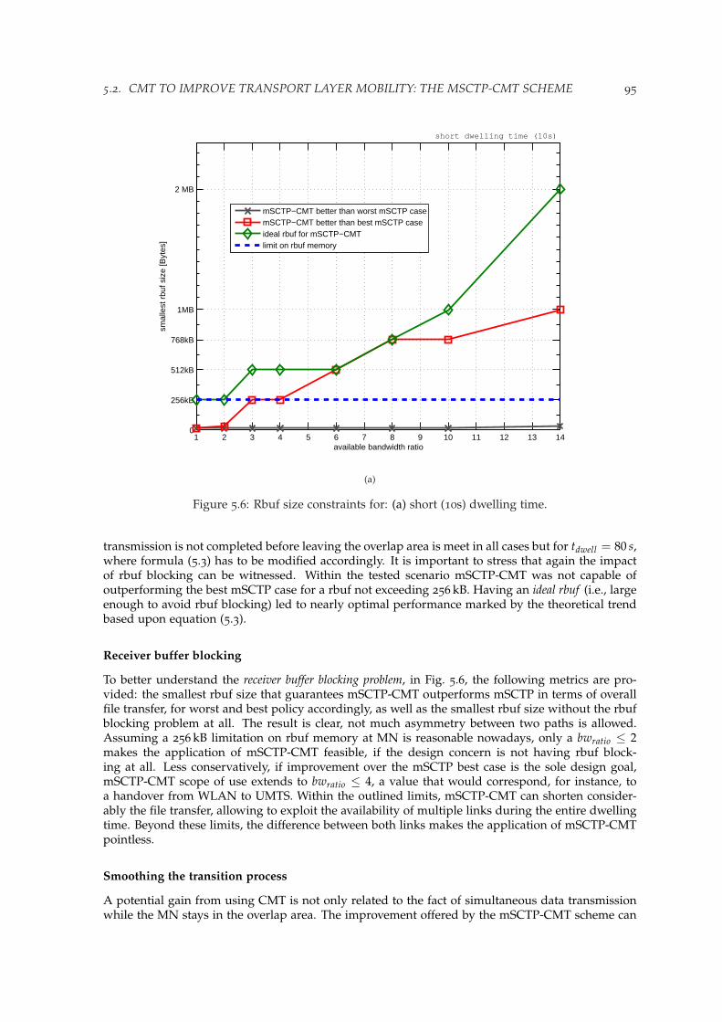
5.2. CMT TO IMPROVE TRANSPORT LAYER MOBILITY: THE MSCTP-CMT SCHEME 95
1 2 3 4 5 6 7 8 9 10 11 12 13 140
256kB
512kB
768kB
1MB
2 MB
available bandwidth ratio
smal
lest
rbu
f siz
e [B
ytes
]
short dwelling time (10s)
mSCTP−CMT better than worst mSCTP casemSCTP−CMT better than best mSCTP caseideal rbuf for mSCTP−CMTlimit on rbuf memory
(a)
Figure 5.6: Rbuf size constraints for: (a) short (10s) dwelling time.
transmission is not completed before leaving the overlap area is meet in all cases but for tdwell = 80 s,where formula (5.3) has to be modified accordingly. It is important to stress that again the impactof rbuf blocking can be witnessed. Within the tested scenario mSCTP-CMT was not capable ofoutperforming the best mSCTP case for a rbuf not exceeding 256 kB. Having an ideal rbuf (i.e., largeenough to avoid rbuf blocking) led to nearly optimal performance marked by the theoretical trendbased upon equation (5.3).
Receiver buffer blocking
To better understand the receiver buffer blocking problem, in Fig. 5.6, the following metrics are pro-vided: the smallest rbuf size that guarantees mSCTP-CMT outperforms mSCTP in terms of overallfile transfer, for worst and best policy accordingly, as well as the smallest rbuf size without the rbufblocking problem at all. The result is clear, not much asymmetry between two paths is allowed.Assuming a 256 kB limitation on rbuf memory at MN is reasonable nowadays, only a bwratio ≤ 2makes the application of mSCTP-CMT feasible, if the design concern is not having rbuf block-ing at all. Less conservatively, if improvement over the mSCTP best case is the sole design goal,mSCTP-CMT scope of use extends to bwratio ≤ 4, a value that would correspond, for instance, toa handover from WLAN to UMTS. Within the outlined limits, mSCTP-CMT can shorten consider-ably the file transfer, allowing to exploit the availability of multiple links during the entire dwellingtime. Beyond these limits, the difference between both links makes the application of mSCTP-CMTpointless.
Smoothing the transition process
A potential gain from using CMT is not only related to the fact of simultaneous data transmissionwhile the MN stays in the overlap area. The improvement offered by the mSCTP-CMT scheme can
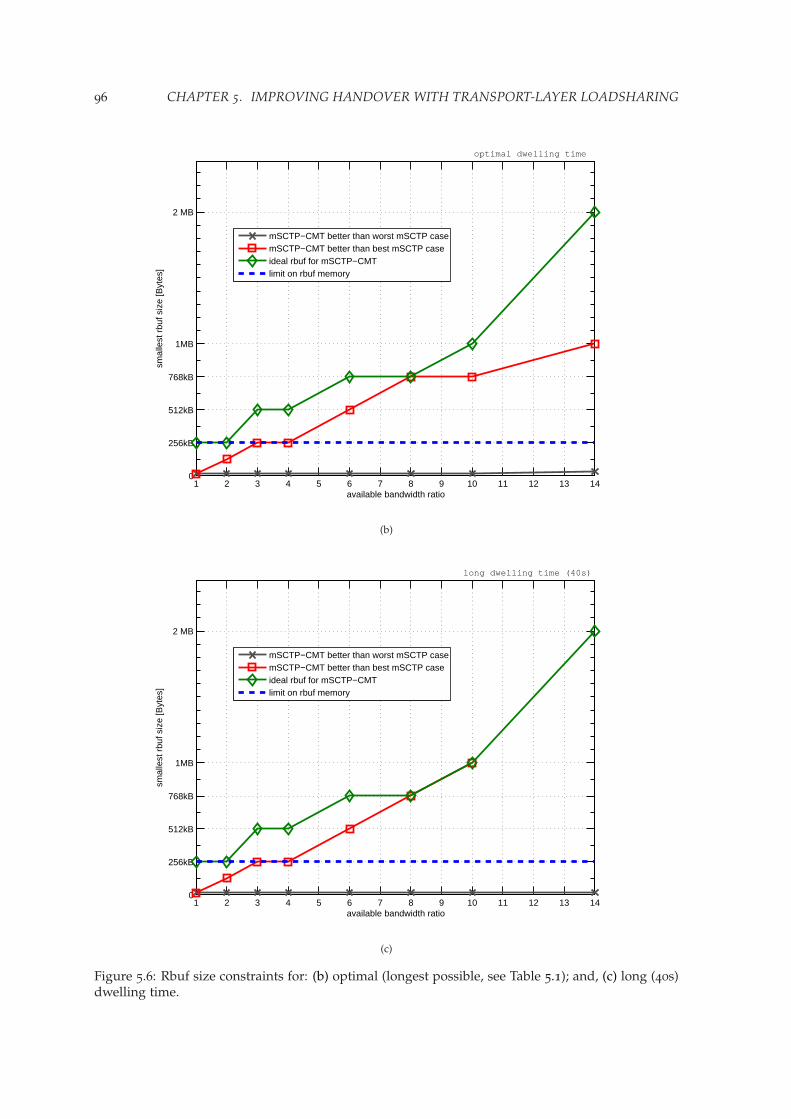
96 CHAPTER 5. IMPROVING HANDOVER WITH TRANSPORT-LAYER LOADSHARING
1 2 3 4 5 6 7 8 9 10 11 12 13 140
256kB
512kB
768kB
1MB
2 MB
available bandwidth ratio
smal
lest
rbu
f siz
e [B
ytes
]optimal dwelling time
mSCTP−CMT better than worst mSCTP casemSCTP−CMT better than best mSCTP caseideal rbuf for mSCTP−CMTlimit on rbuf memory
(b)
1 2 3 4 5 6 7 8 9 10 11 12 13 140
256kB
512kB
768kB
1MB
2 MB
available bandwidth ratio
smal
lest
rbu
f siz
e [B
ytes
]
long dwelling time (40s)
mSCTP−CMT better than worst mSCTP casemSCTP−CMT better than best mSCTP caseideal rbuf for mSCTP−CMTlimit on rbuf memory
(c)
Figure 5.6: Rbuf size constraints for: (b) optimal (longest possible, see Table 5.1); and, (c) long (40s)dwelling time.
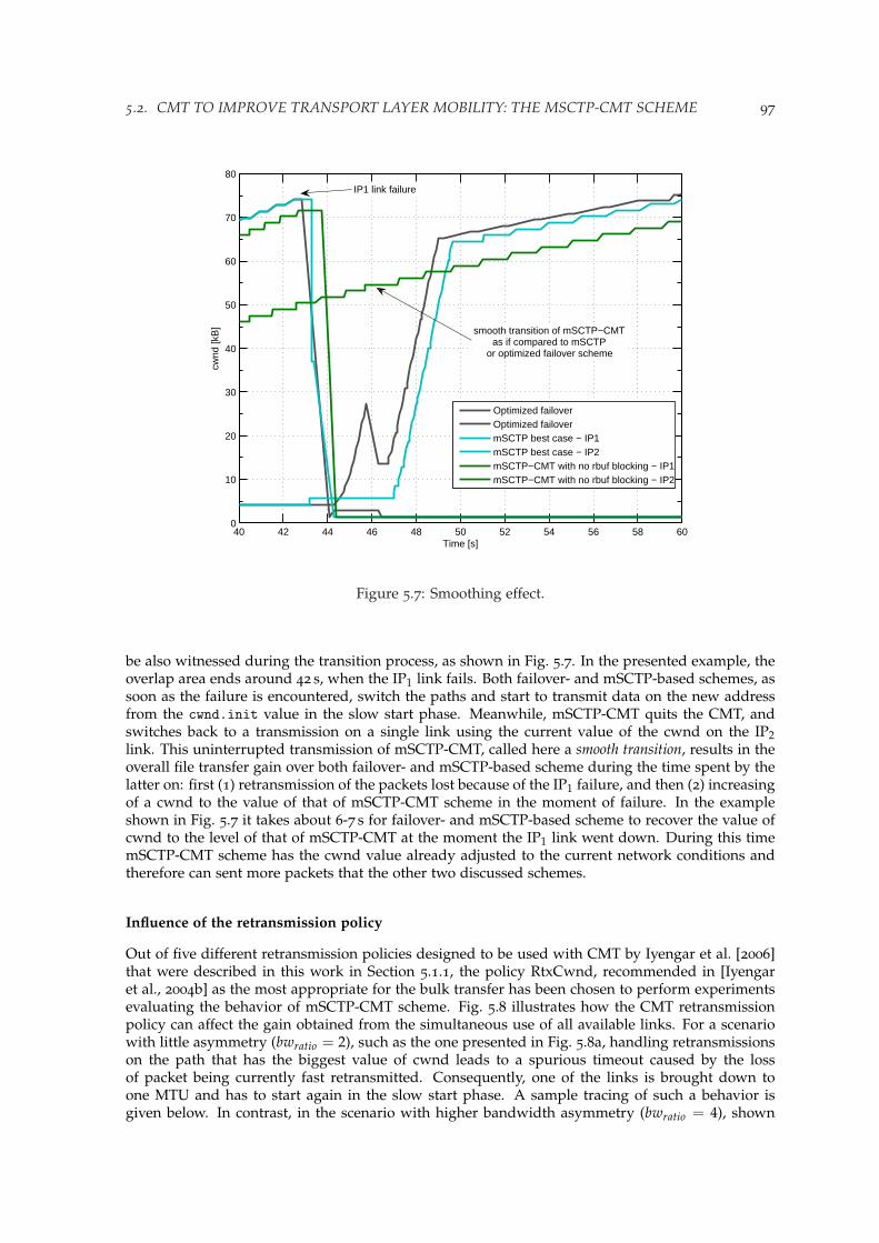
5.2. CMT TO IMPROVE TRANSPORT LAYER MOBILITY: THE MSCTP-CMT SCHEME 97
40 42 44 46 48 50 52 54 56 58 600
10
20
30
40
50
60
70
80
Time [s]
cwnd
[kB
]
Optimized failoverOptimized failovermSCTP best case − IP1mSCTP best case − IP2mSCTP−CMT with no rbuf blocking − IP1mSCTP−CMT with no rbuf blocking − IP2
smooth transition of mSCTP−CMTas if compared to mSCTP
or optimized failover scheme
IP1 link failure
Figure 5.7: Smoothing effect.
be also witnessed during the transition process, as shown in Fig. 5.7. In the presented example, theoverlap area ends around 42 s, when the IP1 link fails. Both failover- and mSCTP-based schemes, assoon as the failure is encountered, switch the paths and start to transmit data on the new addressfrom the cwnd.init value in the slow start phase. Meanwhile, mSCTP-CMT quits the CMT, andswitches back to a transmission on a single link using the current value of the cwnd on the IP2link. This uninterrupted transmission of mSCTP-CMT, called here a smooth transition, results in theoverall file transfer gain over both failover- and mSCTP-based scheme during the time spent by thelatter on: first (1) retransmission of the packets lost because of the IP1 failure, and then (2) increasingof a cwnd to the value of that of mSCTP-CMT scheme in the moment of failure. In the exampleshown in Fig. 5.7 it takes about 6-7 s for failover- and mSCTP-based scheme to recover the value ofcwnd to the level of that of mSCTP-CMT at the moment the IP1 link went down. During this timemSCTP-CMT scheme has the cwnd value already adjusted to the current network conditions andtherefore can sent more packets that the other two discussed schemes.
Influence of the retransmission policy
Out of five different retransmission policies designed to be used with CMT by Iyengar et al. [2006]that were described in this work in Section 5.1.1, the policy RtxCwnd, recommended in [Iyengaret al., 2004b] as the most appropriate for the bulk transfer has been chosen to perform experimentsevaluating the behavior of mSCTP-CMT scheme. Fig. 5.8 illustrates how the CMT retransmissionpolicy can affect the gain obtained from the simultaneous use of all available links. For a scenariowith little asymmetry (bwratio = 2), such as the one presented in Fig. 5.8a, handling retransmissionson the path that has the biggest value of cwnd leads to a spurious timeout caused by the lossof packet being currently fast retransmitted. Consequently, one of the links is brought down toone MTU and has to start again in the slow start phase. A sample tracing of such a behavior isgiven below. In contrast, in the scenario with higher bandwidth asymmetry (bwratio = 4), shown

98 CHAPTER 5. IMPROVING HANDOVER WITH TRANSPORT-LAYER LOADSHARING
0 10 20 30 40 50 600
10
20
30
40
50
60
70
80
Time [s]
cwnd
[kB
]
mSCTP best case − IP1mSCTP best case − IP2mSCTP−CMT with no rbuf blocking − IP1mSCTP−CMT with no rbuf blocking − IP2
dwelling time = 40 s
spurioustimeout
retransmission
(a)
0 10 20 30 40 50 600
10
20
30
40
50
60
70
80
90
Time [s]
cwnd
[kB
]
mSCTP best case − IP1mSCTP best case − IP2mSCTP−CMT with no rbuf blocking − IP1mSCTP−CMT with no rbuf blocking − IP2
dwelling time = 40 s
gain over mSCTP is causedby the retransmission policy
used for mSCTP−CMT
end of transmission
(b)
Figure 5.8: Influence of the retransmission policy RtxCwnd on the mSCTP-CMT behavior: (a) spu-rious timeout retransmission; and, (b) additional gain.

5.2. CMT TO IMPROVE TRANSPORT LAYER MOBILITY: THE MSCTP-CMT SCHEME 99
in Fig. 5.8b, the proposed retransmission policy results in better performance when mSCTP-CMTis compared to the failover- or mSCTP-based scheme (both handle fast retransmission on the samepath where it occurred). With mSCTP-CMT using RtxCwnd policy, the faster path can start newdata transmission without needing to wait until the retransmission ends on the slower path.
Occurrence of spurious timeout retransmissions in function of retransmission policy applied toCMT has already been investigated in more detail by Iyengar et al. [2006]. As shown in the exampleprovided here, the choice of the loss-based policy aiming to pick the path with the lowest estimatedloss rate, and thus minimize the probability of a spurious failover, does not guarantee avoidingcompletely this type of events. An open question, left for the future research, is further evaluationwhether relying on the cwnd value to select the path for the retransmission is the most appropriateapproach in the handover scenarios.
Tracing for mSCTP-CMT with RtxCwnd policy leading to a spurious timeout
Sample of simplified ns-2 tracing provided here has the following format in the subsequent fields:1 - event: pkt enqueued (+), dequeued (-), received (r) or dropped (d); 2 - time; 3 - source node id(CN: 1,2; intermediate router: 6,7; MN: 4,5); 4 - destination node id (node 4 has address IP1, andnode 5 has address IP2); 5 - protocol name (sctp); 6 - packets size; 7 - chunk type: DATA (——-D),SACK (——-S), HB (——-H) and HB-ACK (——-B); 8 - TSN; 9 - packet id; 10 - stream id (SID); 11 -stream sequence number (SSN).
Explanation of the symbols additionally used in the provided tracing example: saddr - sourceaddress; daddr - destination address; pba - partial bytes acked; out - number of outstanding byteson a given destination; peerRwnd - peer rwnd size; rto - RTO value.
Comments (in italics) are marked in-line.
packet is initially lost at daddr: 5 (node ids for this path: 2-7-5)
+ 18.475849 7 5 sctp 1500 -------D 1690 2497 0 1689d 18.475849 7 5 sctp 1500 -------D 1690 2497 0 1689saddr: 2 daddr: 5 cwnd: 79248 pba: 216 out: 77804 ssthresh: 65536peerRwnd: 289408 rto: 3.134...
drop detection:
r 18.502478 7 2 sctp 168 -------S 1527 2488 65535 65535r 18.564978 7 2 sctp 168 -------S 1534 2498 65535 65535r 18.627478 7 2 sctp 168 -------S 1540 2507 65535 65535r 18.689978 7 2 sctp 168 -------S 1546 2516 65535 65535...r 20.002395 7 2 sctp 164 -------S 1674 2707 65535 65535r 20.064895 7 2 sctp 164 -------S 1680 2716 65535 65535r 20.127395 7 2 sctp 164 -------S 1686 2725 65535 65535...r 20.158188 6 1 sctp 168 -------S 1689 2736 65535 65535r 20.189978 7 2 sctp 168 -------S 1689 2734 65535 65535r 20.205104 6 1 sctp 172 -------S 1689 2745 65535 65535r 20.220688 6 1 sctp 168 -------S 1689 2746 65535 65535
3 Dup Gap ACK reports on the same path, reduce cwnd to half at daddr: 5
(start fast rtx, fast recovery exit point: 1855)
time: 20.22069 saddr: 1 daddr: 4 cwnd: 66782time: 20.22069 saddr: 2 daddr: 5 cwnd: 40358
FAST RTX to daddr: 4 is triggered (node ids for this path: 1-6-4):
time: 20.22069 saddr: 1 daddr: 4 RTX TSN: 1690time: 20.22069 saddr: 1 daddr: 4 cwnd: 66782 pba: 60404 out: 66060

100 CHAPTER 5. IMPROVING HANDOVER WITH TRANSPORT-LAYER LOADSHARING
ssthresh: 38890 peerRwnd: 276196 rto: 0.922+ 20.220688 1 6 sctp 1500 -------D 1690 2751 0 1689- 20.220688 1 6 sctp 1500 -------D 1690 2751 0 1689r 20.225808 1 6 sctp 1500 -------D 1690 2751 0 1689+ 20.225808 6 4 sctp 1500 -------D 1690 2751 0 1689- 20.887049 6 4 sctp 1500 -------D 1690 2751 0 1689r 20.917674 6 4 sctp 1500 -------D 1690 2751 0 1689+ 20.933299 4 6 sctp 164 -------S 1772 2831 65535 65535r 20.955021 6 1 sctp 164 -------S 1772 2831 65535 65535FAST RTX completed successfully before timeout
meanwhile another packet on the slower link is dropped:
+ 20.158188 2 7 sctp 1500 -------D 1855 2743 0 1854- 20.158188 2 7 sctp 1500 -------D 1855 2743 0 1854r 20.163308 2 7 sctp 1500 -------D 1855 2743 0 1854+ 20.163308 7 5 sctp 1500 -------D 1855 2743 0 1854d 20.163308 7 5 sctp 1500 -------D 1855 2743 0 1854saddr: 2 daddr: 5 cwnd: 80716 pba: 240 out: 79272 ssthresh: 65536peerRwnd: 287940 rto: 2.936
drop detection:
r 21.844638 6 1 sctp 68 -------S 0 1854 2959 65535 65535r 21.875387 7 2 sctp 68 -------S 0 1854 2957 65535 65535r 21.891513 6 1 sctp 68 -------S 0 1854 2967 65535 65535r 21.907138 6 1 sctp 68 -------S 0 1854 2968 65535 655353 Dup Gap ACK reports on the same path, do not reduce cwnd at daddr: 5
(still in fast recovery)
time: 21.90714 saddr: 1 daddr: 4 cwnd: 71186time: 21.90714 saddr: 2 daddr: 5 cwnd: 43294
FAST RTX triggered:
time: 21.90714 saddr: 1 daddr: 4 RTX TSN: 1855time: 21.90714 saddr: 1 daddr: 4 cwnd: 71186 pba: 14198 out: 71932ssthresh: 38890 peerRwnd: 312896 rto: 0.777+ 21.907138 1 6 sctp 1500 -------D 1855 2973 0 1854- 21.907138 1 6 sctp 1500 -------D 1855 2973 0 1854r 21.912258 1 6 sctp 1500 -------D 1855 2973 0 1854+ 21.912258 6 4 sctp 1500 -------D 1855 2973 0 1854- 22.621424 6 4 sctp 1500 -------D 1855 2973 0 1854r 22.652049 6 4 sctp 1500 -------D 1855 2973 0 1854+ 22.683299 4 6 sctp 64 -------S 1989 3087 65535 65535- 22.683299 4 6 sctp 64 -------S 1989 3087 65535 65535r 22.698966 4 6 sctp 64 -------S 1989 3087 65535 65535+ 22.698966 6 1 sctp 64 -------S 1989 3087 65535 65535- 22.698966 6 1 sctp 64 -------S 1989 3087 65535 65535r 22.703971 6 1 sctp 64 -------S 1989 3087 65535 65535FAST RTX completed successfully but after timeout expiration!!!
Timeout expires on daddr: 4
time: 22.68463 saddr: 1 sport: 0 daddr: 4 dport: 0 DataTimeout,peerRwnd: 199860 rto: 0.913+ 22.684631 1 6 sctp 56 -------H -1 3089 65535 65535- 22.684631 1 6 sctp 56 -------H -1 3089 65535 65535r 22.689635 1 6 sctp 56 -------H -1 3089 65535 65535+ 22.689635 6 4 sctp 56 -------H -1 3089 65535 65535

5.2. CMT TO IMPROVE TRANSPORT LAYER MOBILITY: THE MSCTP-CMT SCHEME 101
- 23.402674 6 4 sctp 56 -------H -1 3089 65535 65535r 23.418257 6 4 sctp 56 -------H -1 3089 65535 65535+ 23.418257 4 6 sctp 56 -------B -1 3170 65535 65535- 23.418257 4 6 sctp 56 -------B -1 3170 65535 65535r 23.433841 4 6 sctp 56 -------B -1 3170 65535 65535+ 23.433841 6 1 sctp 56 -------B -1 3170 65535 65535- 23.433841 6 1 sctp 56 -------B -1 3170 65535 65535r 23.438845 6 1 sctp 56 -------B -1 3170 65535 65535
Timeout RTX triggered:
time: 22.68463 saddr: 2 daddr: 5 RTX TSN: 1855time: 22.68463 saddr: 2 daddr: 5 cwnd: 44762 pba: 24980 out: 45508ssthresh: 40358 peerRwnd: 199860 rto: 2.965+ 22.684631 2 7 sctp 1500 -------D 1855 3088 0 1854- 22.684631 2 7 sctp 1500 -------D 1855 3088 0 1854r 22.689751 2 7 sctp 1500 -------D 1855 3088 0 1854+ 22.689751 7 5 sctp 1500 -------D 1855 3088 0 1854- 23.521465 7 5 sctp 1500 -------D 1855 3088 0 1854r 23.632715 7 5 sctp 1500 -------D 1855 3088 0 1854+ 23.632715 5 7 sctp 72 -------S 2076 3196 65535 65535- 23.632715 5 7 sctp 72 -------S 2076 3196 65535 65535r 23.714215 5 7 sctp 72 -------S 2076 3196 65535 65535+ 23.714215 7 2 sctp 72 -------S 2076 3196 65535 65535- 23.714215 7 2 sctp 72 -------S 2076 3196 65535 65535r 23.719221 7 2 sctp 72 -------S 2076 3196 65535 65535
5.2.4 Extended performance evaluation
In further evaluation of the mSCTP-CMT scheme, small modifications will be introduced to theproposed scenario under test (Fig. 5.2). First, four different values of propagation delay are providedto evaluate the mSCTP-CMT performance in various RTT conditions. Then, two different patternsof the mobility scenario are considered: (1) transition from fast to slow RAN, and (2) from slow tofast RAN, accordingly. Table 5.2 summarizes all parameters that were modified with respect to thebasic scenario configuration, described in Table 5.1. Some of the result provided by this analysiswere published in [Budzisz, Ferrus, and Casadevall, 2009].
RTT value
As there was not much difference in the performance of mSCTP-CMT for four considered RTT cases(according to Table 5.2) only the results for both ends of the considered RTT range were marked inFig. 5.9. Again, as in case of the basic performance analysis (Section 5.2.3), the dwelling time graphreveals that mSCTP-CMT does not perform any better (but any worse either) than the remaininghandover schemes in case of short tdwell values (i.e., tdwell ≤ 5 s). For tdwell ≥ 10 s a considerable
Table 5.2: Parameters modified for further evaluation of mSCTP-CMT
Parameter name Value / Range
Wired part (each path) bandwidth: 100 Mbpsone-way propagation delay: 5-20-45-90 ms
scenario pattern #1: fast-to-slow change RAN #1: fast RANRAN #2: slow RAN
scenario pattern #2: slow-to-fast change RAN #1: slow RANRAN #2: fast RAN

102 CHAPTER 5. IMPROVING HANDOVER WITH TRANSPORT-LAYER LOADSHARING
0 10 20 30 40 50 60 70 8040
60
80
100
120
140
160
180
200
dwelling time [s]
File
tran
sfer
tim
e [s
]
bwratio = 2
RTT min: mSCTP best caseRTT max: mSCTP best caseRTT min: mSCTP−CMT with rbuf 128kBRTT max: mSCTP−CMT with rbuf 128kBRTT min: mSCTP−CMT with ideal rbufRTT max: mSCTP−CMT with ideal rbuf
(a)
0 5 10 15 20 25 30 35 4020
40
60
80
100
120
140
160
180
dwelling time [s]
File
tran
sfer
tim
e [s
]
bwratio = 4
RTT min: mSCTP best caseRTT max: mSCTP best caseRTT min: mSCTP−CMT with rbuf 128kBRTT max: mSCTP−CMT with rbuf 128kBRTT min: mSCTP−CMT with ideal rbufRTT max: mSCTP−CMT with ideal rbuf
(b)
Figure 5.9: Comparison for different RTT values in function of dwelling time for: (a) bwratio = 2;and, (b) bwratio = 4.

5.2. CMT TO IMPROVE TRANSPORT LAYER MOBILITY: THE MSCTP-CMT SCHEME 103
2 4 6 8 10 12 14 16 18 2020
40
60
80
100
120
140
160
180
dwelling time [s]
File
tran
sfer
tim
e [s
]
bwratio = 6
RTT min: mSCTP best caseRTT max: mSCTP best caseRTT min: mSCTP−CMT with rbuf 128kBRTT max: mSCTP−CMT with rbuf 128kBRTT min: mSCTP−CMT with ideal rbufRTT max: mSCTP−CMT with ideal rbuf
(c)
2 4 6 8 10 12 14 16 18 200
20
40
60
80
100
120
140
160
180
dwelling time [s]
File
tran
sfer
tim
e [s
]
bwratio = 8
RTT min: mSCTP best caseRTT max: mSCTP best caseRTT min: mSCTP−CMT with rbuf 128kBRTT max: mSCTP−CMT with rbuf 128kBRTT min: mSCTP−CMT with ideal rbufRTT max: mSCTP−CMT with ideal rbuf
(d)
Figure 5.9: Comparison for different RTT values in function of dwelling time for: (c) bwratio = 6;and, (d) bwratio = 8.

104 CHAPTER 5. IMPROVING HANDOVER WITH TRANSPORT-LAYER LOADSHARING
1 2 3 4 5 6 7 8 9 10 11 12 13 140
256kB
512kB
768kB
1MB
2 MB
available bandwidth ratio
smal
lest
rbu
f siz
e [B
ytes
]short dwelling time (10s)
RTT min: mSCTP−CMT better than best mSCTP caseRTT max: mSCTP−CMT better than best mSCTP caseRTT min: ideal rbuf for mSCTP−CMTRTT max: ideal rbuf for mSCTP−CMTlimit on rbuf memory
(a)
Figure 5.10: Rbuf size constraints for different RTT values: (a) short (10s) dwelling time.
gain can be noticed, however the performance is strongly constrained by the rbuf blocking problem.Varying RTT did not change this tendency: mSCTP-CMT was not capable of outperforming bestmSCTP case for a rbuf not exceeding 256 kB for bwratio equal to 4. For bwratio = 2 already 128 kBbuffer guaranteed much better performance than mSCTP for all investigated values of RTT. Forthe two biggest analyzed values of bwratio (i.e, 6 and 8), rbuf blocking problem forced having nearlyideal rbuf size, significantly exceeding 256 kB in order to provide improvement over the best mSCTPscheme.
To quantify the constraints introduced by rbuf blocking problem for a given limitation on therbuf memory size set to 256 kB, the same metrics as in case of basic analysis are used: the smallestrbuf size that guarantees mSCTP-CMT outperforms mSCTP in terms of overall file transfer, for worstand best policy accordingly, as well as the smallest rbuf size without the rbuf blocking problem atall. Fig. 5.10 shows clearly that, independently of the RTT value, always that the bwratio ≤ 2, themSCTP-CMT algorithm can bring a given gain over the best mSCTP strategy, if the design concernis not having rbuf blocking at all. If the design approach allows some rbuf blocking aiming only atimproving the result of mSCTP, the scope of use of mSCTP-CMT extends to bwratio of three or evenfour in function of considered RTT. Beyond this limit, the difference between both links makes theapplication of mSCTP-CMT pointless. This is hold true for all considered tdwell values.
Mobility pattern
Last aspect that will be evaluated in the presented analysis of mSCTP-CMT is the influence of thetransition type. Similarly to Fig. 5.4, a performance comparison in terms of TSN-time evolutiondiagram for slow-to-fast RAN transition is presented in Fig. 5.11. As can be seen the transition typeis a factor not influencing much the presented scenario. In both cases (fast-to-slow and slow-to-fasttransition) the gain will be produced in the overlap area (2-42 s in the time scale) if the rbuf size isappropriately adjusted. Also bwratio and tdwell settings are considerably more important than the

5.2. CMT TO IMPROVE TRANSPORT LAYER MOBILITY: THE MSCTP-CMT SCHEME 105
1 2 3 4 5 6 7 8 9 10 11 12 13 140
256kB
512kB
768kB
1MB
2 MB
available bandwidth ratio
smal
lest
rbu
f siz
e [B
ytes
]
optimal dwelling time
RTT min: mSCTP−CMT better than best mSCTP caseRTT max: mSCTP−CMT better than best mSCTP caseRTT min: ideal rbuf for mSCTP−CMTRTT max: ideal rbuf for mSCTP−CMTlimit on rbuf memory
(b)
1 2 3 4 5 6 7 8 9 10 11 12 13 140
256kB
512kB
768kB
1MB
2 MB
available bandwidth ratio
smal
lest
rbu
f siz
e [B
ytes
]
long dwelling time (40s)
RTT min: mSCTP−CMT better than best mSCTP caseRTT max: mSCTP−CMT better than best mSCTP caseRTT min: ideal rbuf for mSCTP−CMTRTT max: ideal rbuf for mSCTP−CMTlimit on rbuf memory
(c)
Figure 5.10: Rbuf size constraints for different RTT values: (b) optimal (longest possible, see Ta-ble 5.1); and, (c) long (40s) dwelling time.

106 CHAPTER 5. IMPROVING HANDOVER WITH TRANSPORT-LAYER LOADSHARING
0 20 40 60 80 100 120 140 160 180 2000
1000
2000
3000
4000
5000
6000
Time [s]
Cum
ulat
ive
TS
N
Single link SCTPOptimized failovermSCTP best casemSCTP worst casemSCTP−CMT with no rbuf blockingmSCTP−CMT rbuf blocking
Range ofpossiblemSCTP
performance
Range ofpossible
mSCTP−CMTperformance
without rbuf blockingmSCTP−CMT performs better than
mSCTP best case
EOF = 5778
(a)
5 10 15 20 25 30 35 40 45 50
1000
2000
3000
4000
5000
6000
Time [s]
Cum
ulat
ive
TS
N
Single link SCTPOptimized failovermSCTP best casemSCTP worst casemSCTP−CMT with no rbuf blockingmSCTP−CMT rbuf blocking
Range ofpossiblemSCTP
performanceRange ofpossible
mSCTP−CMTperformance
without rbuf blockingmSCTP−CMT performs better
than mSCTP best case
dwelling time = 40 s
EOF = 5778
(b)
Figure 5.11: Performance comparison of all SCTP versions for bwratio = 4, and tdwell = 40 s: (a)entire file transfer; and, (b) overlap area only.

5.3. FUTURE WORK 107
ACTIVE
RTO.min=0
(send data)
PF
RTO.min=0
(send HB at
constant rate)1 st
Tim
eout
FAILED
State
(send HB)
HB_ACK
ACKTimeout
(PM
R+1)
thTim
eout
Timeout and
total < (PMR+1)
consecutive TimeoutsH
B_A
CK
Figure 5.12: Failure detection in CMT-PF with frequent line probing.
analyzed transition type.
5.3 Future work
Readers interested in further development of the CMT application in the handover scenarios willfind in this section some ideas that may be helpful for their future work.
5.3.1 ABC in slow start
In order to increase the gain introduced when using the CMT, it may be useful to improve the slowstart phase on the new path (to get it fully running as fast as possible).
The first idea that comes into mind is to remove the delayed SACK mechanism (within the stan-dard SCTP, a SACK is sent every second packet), already described here when discussing similarissue in failover context in Section 4.3.1, in order to increase the cwnd growth pace. The cost ofsuch decision is a more intense SACK traffic on the link. In wireless scenarios the wasted mobileterminal energy spent on unnecessary SACK transmissions may have serious consequences, suchas reduction of battery lifetime. Another approach to this problem, and possibly a better solutionin the context of wireless scenarios is to modify slightly protocol behavior and preserve the delayedSACK mechanism. SCTP’s Free-BSD implementation [SCTP-FreeBSD] includes a parameter calledthe sctpabc (ABC stands for Appropriate Byte Counting) that manages the growth of the conges-tion window in the slow start phase. Standard SCTP, on the reception of the SACK that advancesCumTSN, increases the window by the smaller of two: sctpabc × PathMTU and the number of Bytesacknowledged, with sctpabc set by default to 1. Setting the sctpabc to 2 will lead to the same effect,as no delayed SACKs without the increase of SACK traffic.

108 CHAPTER 5. IMPROVING HANDOVER WITH TRANSPORT-LAYER LOADSHARING
5.3.2 More frequent link probing schemes
Nevertheless the CMT-PF reduces rbuf blocking problem, in case of mobility scenarios the mostcrucial issue is to get the information about the state of the path as frequent as possible due to thechanges experienced at the radio link. Therefore, the idea, the author propose to discuss (Fig. 5.12)is to sent the HB on a constant rate of the RTO from the moment of failure, instead of on anexponentially-increasing-RTO basis, once the path is marked as the PF. This will guarantee frequent,PMR-independent path probing, and once the PMR limit is hit the path is considered inactive, and thestandard SCTP’s HB sending pace will be applied.
5.4 Conclusions
Provided that mSCTP itself lacks handover policies, CMT can be seen as an added value to sucha transport-layer handover scheme. CMT (or strictly speaking CMT-PF) introduced by the authorto the mSCTP-based handover scenarios in a scheme called mSCTP-CMT, has proved to have thepotential of smoothing the handover process between two paths, as well as providing an additionalgain due to the simultaneous data transmission over multiple paths available in the overlap area.An initial evaluation reports that a significant gain over the best possible mSCTP strategy can beachieved (in the range of up to 35% of total file transmission time). The main drawback is owedto the strong influence of the receiver buffer blocking on any scenario where the mSCTP-CMT isused, resulting in a firm limitation of possible application area in terms of receiver buffer size. Thenext important factor, scenario asymmetry, measured here as the available bandwidth ratio, putsalso strong constraints on design of such system. Still, as initial results demonstrate, all mentionedlimitations allow the mSCTP-CMT to fit into the future heterogeneous scenarios.
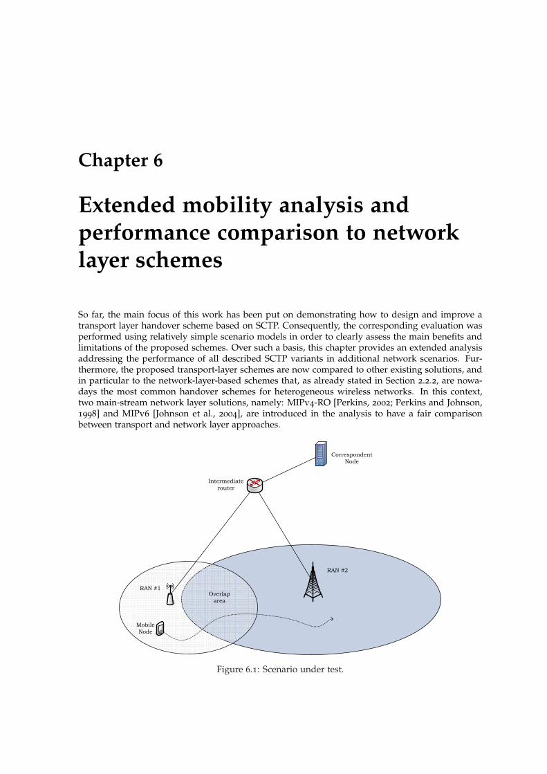
Chapter 6
Extended mobility analysis andperformance comparison to networklayer schemes
So far, the main focus of this work has been put on demonstrating how to design and improve atransport layer handover scheme based on SCTP. Consequently, the corresponding evaluation wasperformed using relatively simple scenario models in order to clearly assess the main benefits andlimitations of the proposed schemes. Over such a basis, this chapter provides an extended analysisaddressing the performance of all described SCTP variants in additional network scenarios. Fur-thermore, the proposed transport-layer schemes are now compared to other existing solutions, andin particular to the network-layer-based schemes that, as already stated in Section 2.2.2, are nowa-days the most common handover schemes for heterogeneous wireless networks. In this context,two main-stream network layer solutions, namely: MIPv4-RO [Perkins, 2002; Perkins and Johnson,1998] and MIPv6 [Johnson et al., 2004], are introduced in the analysis to have a fair comparisonbetween transport and network layer approaches.
Correspondent
Node
Intermediate
router
RAN #2
RAN #1
Mobile
Node
Overlap
area
Figure 6.1: Scenario under test.

110 CHAPTER 6. EXTENDED MOBILITY ANALYSIS
time
...
T4T3T2
Dwelling time (tdwell)
Tn+1T1 D1 D3D2 Dn
RAN #1 only RAN #2 only
Both RANs
are available
1
dwellt
n
i
i
D
Figure 6.2: Mobility model for the presented analysis.
Table 6.1: Mobility patterns
Value of n Pattern Description
1 N/A simple scenario:both RANs are available during entire dwelling time
(Section 6.2.1)3 1-1 (2-2) advanced scenario #1:
stable availability of one of the RANs in the overlap area(Section 6.2.2)
3 1-2 advanced scenario #2:changing availability of RANs inside the overlap area
(Section 6.2.3)
6.1 Preeliminaries
6.1.1 Scenario description
The scenario under test (Fig. 6.1) proposed for the series of analysis presented in this chapterreuses the topology presented already in Chapter 5. Analogously, a MN is moving from RAN #1coverage area towards the coverage area of a neighboring RAN #2 traversing across the overlaparea. However this time, the model of the overlap area has been improved to better reflect thecharacteristics of a handover scenario in future wireless heterogeneous networks [Zahran et al.,2008]. Fig. 6.2 illustrates the overlap area model that will be applied. The main parameter is n,number of periods when both RANs are simultaneously available. Two different values of n (1 and3) are proposed to capture different mobility patterns, and Table 6.1 further describes the detailsof each pattern analyzed. tdwell counts for the entire period when MN can be connected to eitherone or both RANs. Periods of availability of each RAN inside the overlap area (pattern’s namingconvention reflects the availability of each RAN, e.g., 1-1 means that RAN #1 is the only RANavailable in both periods between three overlap ares) are adjusted in function of the MN’s speed,and are exponentially distributed random variables. Parameter δ reflects the ratio between the timewhen both RANs are simultaneously available and the dwelling time. Summary of all scenarioparameters will be given in Table 6.8, but first all handover schemes are defined and explained.
6.1.2 Analyzed handover schemes
The following five mobility schemes will be taken into account in the presented analysis: (1) failover-based, (2) mSCTP, (3) mSCTP-CMT-PF (additionally mSCTP-CMT without the PF extension [Natara-jan et al., 2009, 2006] is tested in the simplest scenario in Section 6.2.1), (4) MobileIPv4-RO, and (5)MobileIPv6. Next, each of the presented schemes is described in more details, with parameters

6.1. PREELIMINARIES 111
specific for each scheme given in a separate table, correspondingly.
Scheme #1: optimized failover-based mSCTP handover scheme. A handover scheme with thestandard SCTP failover mechanism adapted for the handover scenarios (necessary parameter tune-up) and used to trigger the handover. This scheme has been introduced and described in Chapter 4,here the most important details are given in Table 6.2.
Table 6.2: Failover-based mSCTP handover scheme details
Parameter name Value / Range
PMR 1RTO.min 0 msHandover strategy no handover policy defined
primary path change is triggered with failover,Transport layersignaling
Add IP policy:sent if the new interface has been up for τAddIP,
and its address does not belong to the associationSet Primary Address policy:
not sentDelete IP Address policy:
sent when the interface has been down for τDeleteIP(most typically sent bundled with data chunk)
Network layersignaling
N/A
Scheme #2: mSCTP handover scheme, with strategy to choose always the faster RAN. As men-tioned in Section 3.3.2, handover schemes based on mSCTP lack an appropriate handover policy.Provided that possible handover policies can be based on the information passed to the transportlayer from lower layers (e.g., signal strength information), the policy proposed for this scheme hasthe strategy that chooses always the fastest RAN (in terms of available bandwidth) out of all theaccess networks that are currently available. Detailed description of this scheme is given in Table 6.3.
Table 6.3: mSCTP handover scheme details
Parameter name Value / Range
PMR 5RTO.min 200 msHandover strategy use always faster RANTransport layersignaling
Add IP policy:sent if the new interface has been up for τAddIP,
and its address does not belong to the associationSet Primary Address policy:
sent after hysteresis time τChangeIP,from the moment a faster interface is available
Delete IP Address policy:sent when the interface has been down for τDeleteIP
(most typically sent bundled with data chunk)Network layersignaling
N/A

112 CHAPTER 6. EXTENDED MOBILITY ANALYSIS
Scheme #3: mSCTP-CMT-PF handover scheme. A novel design, introduced and described inChapter 5, where the CMT-PF loadsharing scheme is used as an enhancement of the handovermanagement based on mSCTP. Table 6.4 presents more details of this scheme.
Table 6.4: mSCTP-CMT-PF handover scheme details
Parameter name Value / Range
PMR 5RTO.min 200 msHandover strategy as long as two links are available use the CMT-PFTransport layersignaling
Add IP policy:sent if the new interface has been up for τAddIP,
and its address does not belong to the associationSet Primary Address policy:
not sentDelete IP Address policy:
sent when the interface has been down for τDeleteIP(most typically sent bundled with data chunk)
Network layersignaling
N/A
Scheme #3a: mSCTP-CMT handover scheme. A subversion of scheme #3 provided here as abenchmark to demonstrate that the PF extension of the CMT proposed by Natarajan et al. [2006] fitsbetter handover scenarios than the “pure” CMT scheme. Therefore mSCTP-CMT scheme, describedin Table 6.5 is only used in the simplest possible scenario (Section 6.2.1).
Table 6.5: mSCTP-CMT handover scheme details
Parameter name Value / Range
PMR 5RTO.min 200 msHandover strategy As long as two links are available use the CMTTransport layersignaling
Add IP policy:sent if the new interface has been up for τAddIP,
and its address does not belong to the associationSet Primary Address policy:
not sentDelete IP Address policy:
sent when the interface has been down for τDeleteIP(most typically sent bundled with data chunk)
Network layersignaling
N/A
Scheme #4: Network-layer scheme: MIPv4-RO. First of the two analyzed network-layer-basedschemes MIPv4-RO is characterized in Table 6.6. As already described in section 2.2.2, handlingmobility at the network layer transparently for the adjacent SCTP and with minimum routing over-head, requires sending binding update (BU) messages to both HA and CN, informing about thecurrent IP address of the MN. Consequently, each change of the IP address results in a handoverdelay τmipv4−ro, as stated in [Saha et al., 2004]. Value for τmipv4−ro shown in Table 6.8 is calculatedusing this formula and considered scenario parameters.

6.1. PREELIMINARIES 113
The handover strategy proposed for this scheme selects always the fastest RAN in terms of availablebandwidth) out of all the access networks that are currently available.
Table 6.6: MIPv4RO network-layer handover scheme details
Parameter name Value / Range
PMR 5RTO.min 200 msHandover strategy use always faster RANTransport layersignaling
Add IP/Set Primary/Delete IP Address policy:N/A
Network layersignaling
The MN sends a registration request to the FAthat forwards the BU message to the HA.
Then the HA informs the CN about the change.Such a procedure is performed:(1) once a faster interface is up
when the MN has a slow interfaceand (2) when a faster interface is down
and transfer can continue over existing slow interfaceTotal signaling delay:
τmipv4−ro = tMN−HA + tHA−CN + tCN−MN
Scheme #5: Network-layer scheme: MIPv6. Second of the analyzed network-layer-based schemesMIPv6, reduces significantly the signaling necessary to indicate to the CN the change of the IPaddress (τmipv6 is much lower than the corresponding τmipv4−ro) [Saha et al., 2004]. The handoverstrategy is similar to the previously described schemes and selects always the fastest RAN in termsof available bandwidth out of all the access networks that are currently available. Parameters de-scribing this scheme are shown in Table 6.7, whereas the corresponding value of τmipv6 is calculatedin Table 6.8.
Table 6.7: MIPv6 network-layer handover scheme details
Parameter name Value / Range
PMR 5RTO.min 200 msHandover strategy use always faster RANTransport layersignaling
Add IP/Set Primary/Delete IP Address policy:N/A
Network layersignaling
BU message is sent from the MN to the CN:(1) once a faster interface is up
when the MN has a slow interfaceand (2) when a faster interface is down
and transfer can continue over existing slow interfaceTotal signaling delay:
τmipv6 = 2 · tCN−MN
6.1.3 Simulation parameters
Table 6.8 summarizes the list of the most important simulation parameters, including parametersspecific to each of the five handover schemes, calculated for the given scenario topology. The detailsof the radio channel model are described in Appendix A.
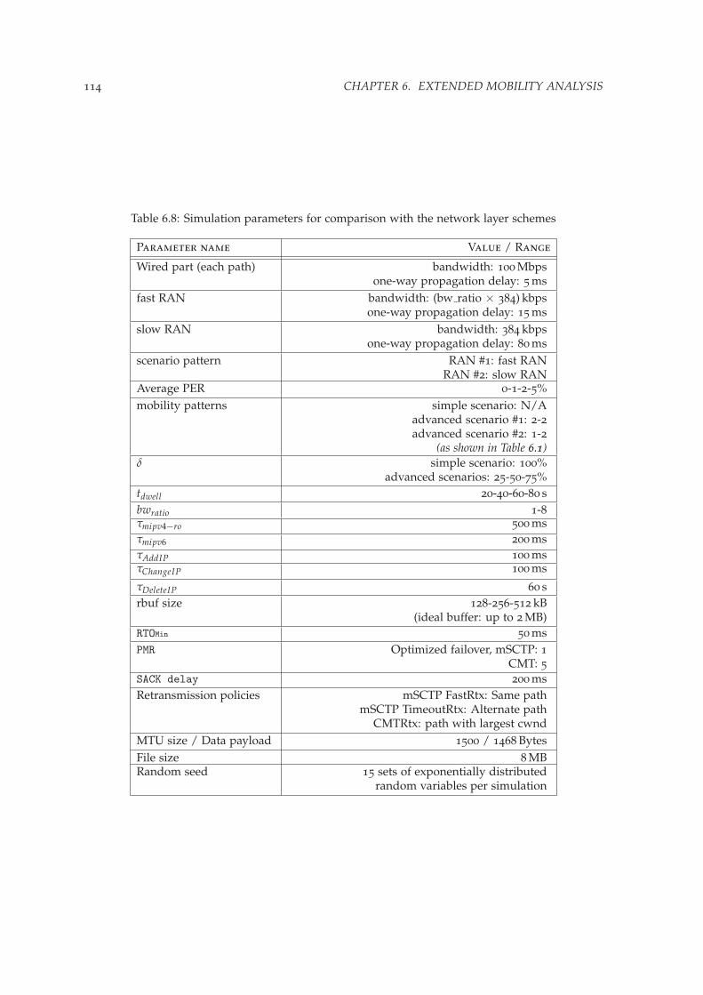
114 CHAPTER 6. EXTENDED MOBILITY ANALYSIS
Table 6.8: Simulation parameters for comparison with the network layer schemes
Parameter name Value / Range
Wired part (each path) bandwidth: 100 Mbpsone-way propagation delay: 5 ms
fast RAN bandwidth: (bw ratio × 384) kbpsone-way propagation delay: 15 ms
slow RAN bandwidth: 384 kbpsone-way propagation delay: 80 ms
scenario pattern RAN #1: fast RANRAN #2: slow RAN
Average PER 0-1-2-5%mobility patterns simple scenario: N/A
advanced scenario #1: 2-2advanced scenario #2: 1-2
(as shown in Table 6.1)δ simple scenario: 100%
advanced scenarios: 25-50-75%tdwell 20-40-60-80 sbwratio 1-8τmipv4−ro 500 msτmipv6 200 msτAddIP 100 msτChangeIP 100 ms
τDeleteIP 60 srbuf size 128-256-512 kB
(ideal buffer: up to 2 MB)RTOMin 50 msPMR Optimized failover, mSCTP: 1
CMT: 5SACK delay 200 msRetransmission policies mSCTP FastRtx: Same path
mSCTP TimeoutRtx: Alternate pathCMTRtx: path with largest cwnd
MTU size / Data payload 1500 / 1468 BytesFile size 8 MBRandom seed 15 sets of exponentially distributed
random variables per simulation

6.2. ANALYSIS RESULTS 115
6.2 Analysis results
6.2.1 Simple scenario (n = 1)
First, a comparison of all described handover schemes is made in a simple scenario, where bothRANs are simultaneously available for the entire dwelling time. Fig. 6.3 presents the results for theaverage file transfer time as a function of available bwratio and packet loss rate for a given tdwell .tdwell = 40 s has been selected as the most interesting case, given that for tdwell = 20 s the time bothlinks were simultaneously available was too short to effectively use the loadsharing and thus have afair comparison to other schemes, whereas for both tdwell = 60 s and 80 s the advantage from the useof loadsharing-based scheme was too evident. Consequently, the application of the mSCTP-CMT-PFscheme is highly recommended for the scenarios, where the MN is likely to stay for a relatively longtime in the overlap area. Now, the influence of the remaining factors will be analyzed for tdwell =40 s. In a scenario without losses, shown in Fig. 6.3a, both CMT-based schemes with the idealbuffer size (the size of the buffer big enough to avoid rbuf blocking) provide the best performanceover the entire scope of analyzed bwratio. Both mSCTP-CMT-PF and mSCTP-CMT perform equallygood in all asymmetrical scenarios (in terms of bandwidth), whereas the only difference appearswhen paths are symmetrical. The PF extension stops sending data packets to a path where the lossoccurred, sending instead a HB packet to probe the path availability. On the positive response thepath gets back to the active state, and the data transmission is resumed. Meanwhile the lost packet(in this case, due to the overflowing of the buffer queue size) is retransmitted on the only pathcurrently available. This algorithm turns out to be more efficient than keeping the failed path activeas in case of CMT without PF extension. Much more difference between both CMT schemes canbe seen for smaller buffer sizes. Results presented here for the buffer size of 128 kB, show clearlythat in presence of rbuf blocking, the PF extension increases significantly protocol’s performance.
1 2 3 4 5 6 7 80
50
100
150
200
250
available bandwidth ratio
Ave
rage
file
tran
sfer
tim
e [s
]
dwelling time 40s, δ = 100%, PER=0%
Optimized failovermSCTPmSCTP−CMT−PF rbuf 128kBmSCTP−CMT−PF ideal buffermSCTP−CMT rbuf 128kBmSCTP−CMT ideal bufferMobileIPv4−ROMobileIPv6
(a)
Figure 6.3: Comparison of various handover schemes in a simple scenario, for the following PERvalues: (a) no losses.

116 CHAPTER 6. EXTENDED MOBILITY ANALYSIS
1 2 3 4 5 6 7 80
50
100
150
200
250
available bandwidth ratio
Ave
rage
file
tran
sfer
tim
e [s
]
dwelling time 40s, δ = 100%, PER=2%
Optimized failovermSCTPmSCTP−CMT−PF rbuf 128kBmSCTP−CMT−PF ideal buffermSCTP−CMT rbuf 128kBmSCTP−CMT ideal bufferMobileIPv4−ROMobileIPv6
(b)
1 2 3 4 5 6 7 8100
120
140
160
180
200
220
240
260
280
300
available bandwidth ratio
Ave
rage
file
tran
sfer
tim
e [s
]
dwelling time 40s, δ = 100%, PER=5%
mSCTP−CMT−PF rbuf 128kBmSCTP−CMT−PF ideal buffermSCTP−CMT rbuf 128kBmSCTP−CMT ideal bufferMobileIPv4−ROMobileIPv6
(c)
Figure 6.3: Comparison of various handover schemes in a simple scenario for the following PERvalues: (b) 2% losses; and, (c) 5% losses.

6.2. ANALYSIS RESULTS 117
Still, even the mSCTP-CMT-PF with only 128 kB of buffer size was not able to outperform theremaining non-loadsharing schemes for bwratio > 2. Both network-layer schemes, as well as mSCTPand failover-based scheme, performed almost in the same way in the given scenario, meaning thathandling the mobility at the network layer, transparently to the transport layer, did not do any harmto the SCTP cwnd evolution. Thus, both network-layer handover delays τmipv4−ro and τmipv6 weresmall enough to provoke just a single packet loss, recoverable by the fast retransmission, and notleading to any timeout.
For a scenario where packet losses are present, both failover-based and mSCTP scheme performunstable, specially when the scenario asymmetry increases, as shown in Fig. 6.3b. Also there aremuch more differences between the other schemes. The range of the bwratio where the CMT-basedschemes with a 128 kB receiver buffer perform better than the network-layer schemes extends tobwratio < 6. Naturally, the mSCTP-CMT-PF scheme with an ideal buffer size works best of allpresented schemes in the entire analyzed scope.
In case the packet loss rate increases to 5% (Fig. 6.3c), for both failover-based and mSCTP-basedscheme there was no single situation where the transmission could be completed in less than 900 stime. This fact, plus the high instability for already 2% of the loss rate, leads to the conclusionthat any of these schemes should not be recommended as the possible solution, in scenarios wherelosses are present. As for the remaining schemes, both network-layer schemes perform noticeablyworse than the mSCTP-CMT-PF, even with the rbuf size of 128 kB in the entire scope of experiment.The mSCTP-CMT-PF scheme is not only the best one in terms of minimum transfer delay, but alsopresents the most stable performance among all presented solutions. Not having the PF extensionavailable yields slightly worse performance, but still permits prevail the network-layer counterpartsfor almost the entire range of the analyzed bandwidth asymmetry (bwratio < 8, corresponding to ascenario with the MN moving from the WLAN to the UMTS network), also with the small size ofthe receiver buffer.
6.2.2 More complex mobility pattern (n = 3) - part 1
Having analyzed the simplest scenario, with both links simultaneously available all the time theMN stays in the overlap area, it is now time to check the influence of the mobility patterns on theperformance of proposed handover schemes. First, a scenario, with stable availability of the RAN#2 in the overlap area and periodical availability of RAN #1 (faster of the two), denoted here as2-2, is analyzed. Fig. 6.4 presents the results for average file transfer time as a function of bwratioin a scenario without losses for three different values of the parameter δ. Parameter δ reflects thefraction of the tdwell that both RANs are simultaneously available in the overlap area, incurringworse performance of the mSCTP-CMT-PF scheme for the lower values of δ. Consequently, thefollowing trend can be noticed: for δ = 25% (Fig. 6.4a) the mSCTP-CMT-PF scheme gets worse thanany scheme but failover-based, for the bwratio > 3 no matter what the receiver buffer size is. Forδ = 50% (Fig. 6.4b) it is already bwratio > 4, whereas for δ = 75% (Fig. 6.4c) the mSCTP-CMT-PFis the best scheme in the entire analyzed scope of bwratio. For the purpose of comparison it is alsoworth to recall here the results from Section 6.2.1 (δ = 100%) that gave the mSCTP-CMT-PF schemea clear advantage for all analyzed bwratio values. Thus, the main conclusion is that an instablecoverage of both RANs in the overlap area, clearly reduces the scope of use of the mSCTP-CMT-PF,when compared to other mobility schemes. MobileIPv6 seems to deal best with such situations asthe solution having the lowest latency out of all the remaining schemes. In contrast, MobileIPv4-RO due to the big value of the τmipv4−ro, performs even worst than the mSCTP scheme, but stillguarantees relatively stable performance, no matter what δ value was.
For 2% packet loss rate (Fig. 6.5) the mSCTP-CMT-PF performs slightly worse than in the samescenario without losses, being better only if both paths have equal bandwidth in case of the lowestδ analyzed (Fig. 6.5a), bwratio < 4 for δ = 50% (Fig. 6.5b), and preserving the best score among allschemes in the entire scenario for the biggest value of δ (Fig. 6.5c). Therefore, an overall conclu-sion for the mSCTP-CMT-PF application in the analyzed handover scenario is that for a comparablebandwidth ratio of both paths, i.e., bwratio not exceeding 2, the use of this scheme improves theperformance of the mSCTP even for a very unstable availability of both paths in the overlap region.Outside of the stated application area, it can be clearly seen that the introduction of the loadshar-

118 CHAPTER 6. EXTENDED MOBILITY ANALYSIS
1 2 3 4 5 6 7 8110
120
130
140
150
160
170
180
190
200
210
available bandwidth ratio
Ave
rage
file
tran
sfer
tim
e [s
]
dwelling time 40s, δ = 25%, PER=0%
Optimized failovermSCTPmSCTP−CMT−PF rbuf 128kBmSCTP−CMT−PF ideal bufferMobileIPv4−ROMobileIPv6
(a)
1 2 3 4 5 6 7 840
60
80
100
120
140
160
180
200
available bandwidth ratio
Ave
rage
file
tran
sfer
tim
e [s
]
dwelling time 40s, δ = 50%, PER=0%
Optimized failovermSCTPmSCTP−CMT−PF rbuf 128kBmSCTP−CMT−PF ideal bufferMobileIPv4−ROMobileIPv6
(b)
Figure 6.4: Comparison of various handover schemes for different values of δ in a scenario withpattern 2-2 and without losses, for: (a) δ = 25%; and, (b) δ = 50%.

6.2. ANALYSIS RESULTS 119
1 2 3 4 5 6 7 820
40
60
80
100
120
140
160
180
200
available bandwidth ratio
Ave
rage
file
tran
sfer
tim
e [s
]
dwelling time 40s, δ = 75%, PER=0%
Optimized failovermSCTPmSCTP−CMT−PF rbuf 128kBmSCTP−CMT−PF ideal bufferMobileIPv4−ROMobileIPv6
(c)
Figure 6.4: Comparison of various handover schemes for different values of δ in a scenario withpattern 2-2 and without losses, for: (c) δ = 75%.
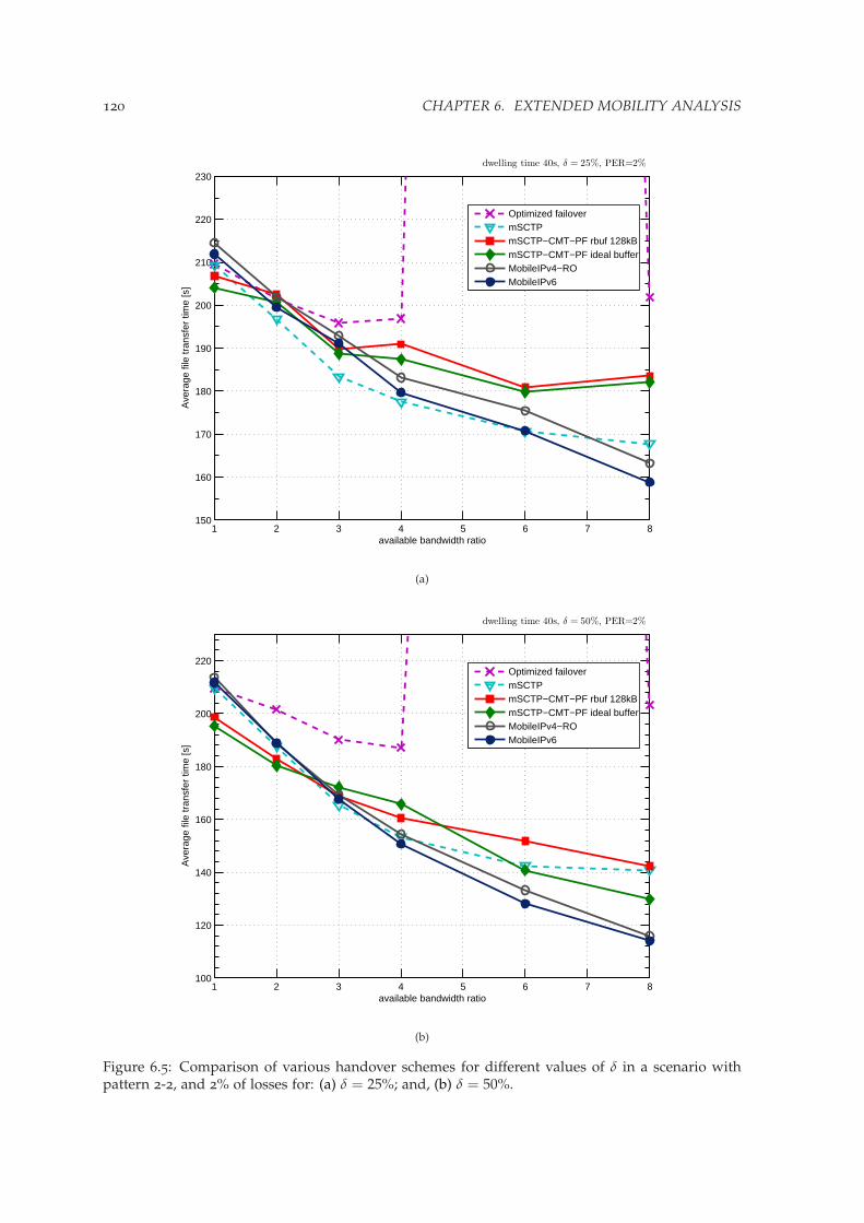
120 CHAPTER 6. EXTENDED MOBILITY ANALYSIS
1 2 3 4 5 6 7 8150
160
170
180
190
200
210
220
230
available bandwidth ratio
Ave
rage
file
tran
sfer
tim
e [s
]
dwelling time 40s, δ = 25%, PER=2%
Optimized failovermSCTPmSCTP−CMT−PF rbuf 128kBmSCTP−CMT−PF ideal bufferMobileIPv4−ROMobileIPv6
(a)
1 2 3 4 5 6 7 8100
120
140
160
180
200
220
available bandwidth ratio
Ave
rage
file
tran
sfer
tim
e [s
]
dwelling time 40s, δ = 50%, PER=2%
Optimized failovermSCTPmSCTP−CMT−PF rbuf 128kBmSCTP−CMT−PF ideal bufferMobileIPv4−ROMobileIPv6
(b)
Figure 6.5: Comparison of various handover schemes for different values of δ in a scenario withpattern 2-2, and 2% of losses for: (a) δ = 25%; and, (b) δ = 50%.
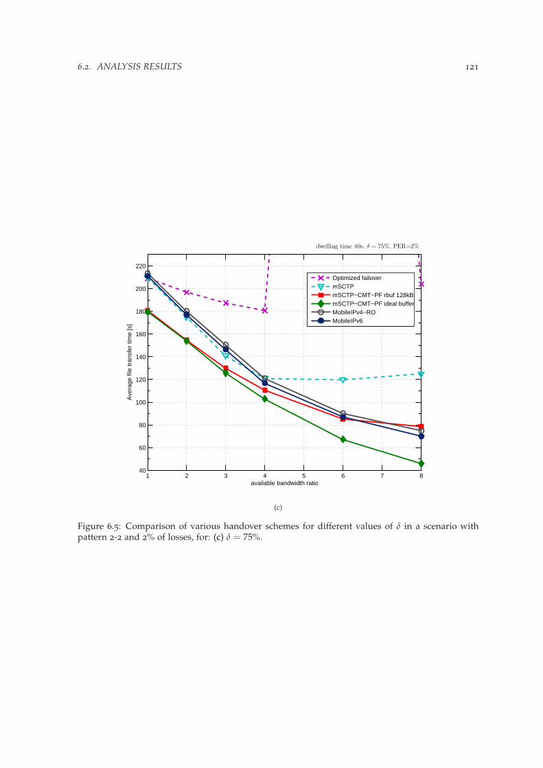
6.2. ANALYSIS RESULTS 121
1 2 3 4 5 6 7 840
60
80
100
120
140
160
180
200
220
available bandwidth ratio
Ave
rage
file
tran
sfer
tim
e [s
]
dwelling time 40s, δ = 75%, PER=2%
Optimized failovermSCTPmSCTP−CMT−PF rbuf 128kBmSCTP−CMT−PF ideal bufferMobileIPv4−ROMobileIPv6
(c)
Figure 6.5: Comparison of various handover schemes for different values of δ in a scenario withpattern 2-2 and 2% of losses, for: (c) δ = 75%.
122 CHAPTER 6. EXTENDED MOBILITY ANALYSIS
ing scheme to the handover transition process deteriorates the performance of the mSCTP. Havingalready numerous retransmissions that must be handled, not only because of the temporal unavail-ability of one of the paths, but also because of the losses present in available radio channels, anyadditional retransmission due to the loadsharing decrease the throughput significantly. Neverthe-less, the mSCTP scheme performs very well only for low value of δ, improving much less than theother schemes when the δ increases, and becoming the worst of all stable schemes for the biggestvalue of δ. Failover-based scheme was again not able to offer any stable performance in presenceof losses, making impossible the trade-off between stable and fast performance due to reduction ofPMR value. In that sense the only valid alternatives become the network layer schemes, as being ableto deal with moderate losses in all three analyzed scenarios.
6.2.3 More complex mobility pattern (n = 3) - part 2
In order to fully understand the influence of handover policies on the overall performance of han-dover scheme it is necessary to test different mobility patterns. This is the most important differencebetween scenarios presented in this Section, were users using always-faster-RAN strategy will beforced to perform at most 2 handovers instead of 3 forced handovers as it was in case of scenariosanalyzed in Section 6.2.2.
Fig. 6.6 represents the results for the average transfer time in a scenario without losses. ThemSCTP-CMT-PF with the ideal buffer size is able to achieve the best performance whenever thebwratio < 3 for the lowest value of δ (Fig. 6.6a). As δ increases, this thresholds extends up tobwratio < 6 for δ = 50% (Fig. 6.6b), and further to bwratio < 8 for the highest value of delta (Fig. 6.6c).The constraints introduced by a limited receiver buffer space would decrease the observed benefits,e.g., having a 128,/kB limitation on the receiver buffer memory leads to the worst performancefrom all presented schemes (worse even than failover based scheme) for the lowest value of δ andall values of bwratio. In such a case there are too many on-going retransmissions that such a smallbuffer can handle. Having δ = 50% was not enough to improve this situation if bwratio > 3, and evenfor the highest value of δ, the failover over-performed the mSCTP-CMT-PF scheme for bwratio >4. Observed behavior is significantly different than the results for the 2-2 scenario presented inSection 6.2.2, due to a decreased amount of mandatory handovers. Nevertheless, the mSCTP-CMT-PF can still be recommended to be applied in the scenarios where bwratio < 3, if only an appropriatereceiver buffer space is available. Otherwise, the scope of use of the mSCTP-CMT-PF scheme isquite limited and highly dependent on the given scenario. Another important consideration is thenoticeable improvement of both network layer schemes, caused by the reduced latency with lowernumber of handovers performed in the overlap area.
With a 2% packet loss existing in the analyzed scenario (Fig. 6.7) further limitation of the use ofthe mSCTP-CMT-PF scheme can be observed. For the lowest value of δ (Fig. 6.7a), the mSCTP-CMT-PF is the worst scheme out of the stable ones, no matter how big the size of receiver buffer is. Forbwratio > 6, the mSCTP-CMT-PF is outperformed even by the failover based-scheme, again beinga consequence of a limited number of handovers. Only the biggest value of δ (Fig. 6.7c) providesthe mSCTP-CMT-PF with an acceptable performance, and again the best of all available schemes.Therefore both MIPv6 or MIPv4-RO can be seen as valid alternatives, especially in the scenariossimilar to the presented one.
6.3 Conclusions
Comparison of all SCTP-based schemes introduced and described in this work was aiming to pro-vide an answer for the question, whether there is a real need for such solutions, given that thenetwork-based schemes are the most common mobility schemes nowadays. Looking at the resultsof the presented analysis, some initial conclusions can be drawn, but any more straightforwardanswer to the aforementioned question, require further evaluation. Provided that there are smallasymmetries between both RANs (i.e., bwratio < 3) and reasonably stable availability of both inthe overlap area (i.e., δ > 50%) the mSCTP-CMT-PF scheme was able to outperform all other ana-lyzed schemes in all presented experiments, also taking into account the difficulties introduced by

6.3. CONCLUSIONS 123
1 2 3 4 5 6 7 840
60
80
100
120
140
160
180
200
available bandwidth ratio
Ave
rage
file
tran
sfer
tim
e [s
]
dwelling time 40s, δ = 25%, PER=0%
Optimized failovermSCTPmSCTP−CMT−PF rbuf 128kBmSCTP−CMT−PF ideal bufferMobileIPv4−ROMobileIPv6
(a)
1 2 3 4 5 6 7 820
40
60
80
100
120
140
160
180
200
available bandwidth ratio
Ave
rage
file
tran
sfer
tim
e [s
]
dwelling time 40s, δ = 50%, PER=0%
Optimized failovermSCTPmSCTP−CMT−PF rbuf 128kBmSCTP−CMT−PF ideal bufferMobileIPv4−ROMobileIPv6
(b)
Figure 6.6: Comparison of various handover schemes for different values of δ in a scenario withpattern 1-2 and without losses, for: (a) δ = 25%; and, (b) δ = 50%.

124 CHAPTER 6. EXTENDED MOBILITY ANALYSIS
1 2 3 4 5 6 7 820
40
60
80
100
120
140
160
180
200
available bandwidth ratio
Ave
rage
file
tran
sfer
tim
e [s
]
dwelling time 40s, δ = 75%, PER=0%
Optimized failovermSCTPmSCTP−CMT−PF rbuf 128kBmSCTP−CMT−PF ideal bufferMobileIPv4−ROMobileIPv6
(c)
Figure 6.6: Comparison of various handover schemes for different values of δ in a scenario withpattern 1-2 and without losses, for: (c) δ = 75%.

6.3. CONCLUSIONS 125
1 2 3 4 5 6 7 8
100
120
140
160
180
200
220
available bandwidth ratio
Ave
rage
file
tran
sfer
tim
e [s
]
dwelling time 40s, δ = 25%, PER=2%
Optimized failovermSCTPmSCTP−CMT−PF rbuf 128kBmSCTP−CMT−PF ideal bufferMobileIPv4−ROMobileIPv6
(a)
1 2 3 4 5 6 7 860
80
100
120
140
160
180
200
220
available bandwidth ratio
Ave
rage
file
tran
sfer
tim
e [s
]
dwelling time 40s, δ = 50%, PER=2%
Optimized failovermSCTPmSCTP−CMT−PF rbuf 128kBmSCTP−CMT−PF ideal bufferMobileIPv4−ROMobileIPv6
(b)
Figure 6.7: Comparison of various handover schemes for different values of δ in a scenario withpattern 1-2 and 2% of losses, for: (a) δ = 25%; and, (b) δ = 50%.

126 CHAPTER 6. EXTENDED MOBILITY ANALYSIS
1 2 3 4 5 6 7 840
60
80
100
120
140
160
180
200
220
available bandwidth ratio
Ave
rage
file
tran
sfer
tim
e [s
]
dwelling time 40s, δ = 75%, PER=2%
Optimized failovermSCTPmSCTP−CMT−PF rbuf 128kBmSCTP−CMT−PF ideal bufferMobileIPv4−ROMobileIPv6
(c)
Figure 6.7: Comparison of various handover schemes for different values of δ in a scenario withpattern 1-2 and 2% of losses, for: (c) δ = 75%.

6.3. CONCLUSIONS 127
a limited receiver buffer space. However, there is some dependency on possible handover scenarioconditions that can lead to suboptimal performance of this scheme, especially with low numberof mandatory handovers, and big asymmetry between neighboring RANs. In contrast, it is quiteclear that failover-based scheme can not be recommended as a possible solution, given its unstableperformance in a presence of packet losses, very typical for wireless scenarios. The usefulness ofthe mSCTP-based scheme also stays in question. In a no-, or little-loss-scenario, mSCTP is able tocompete with both MobileIP-based schemes, being unable to deal with greater number of losses(i.e., 2% or higher). In the presented comparison both network-layer-based schemes present accept-able results, being very competitive to the mSCTP-based schemes, despite the inferred handoverlatency. In this sense, both well-established mobility schemes can be seen as viable solutions, goodenough not to be substituted with any scheme, which scope of use is limited.

128 CHAPTER 6. EXTENDED MOBILITY ANALYSIS

Chapter 7
Conclusions
7.1 Summary
The SCTP protocol, which was initially proposed for transporting signaling messages over IP net-works, has had a considerable impact on the research community during the first eight years sinceits first specification was published. SCTP is now an established general transport protocol, and thepresented dissertation shows that SCTP has a great potential for application in diverse fields. Themain SCTP research interest circles around two of SCTP’s new features: multihoming and multi-streaming, which are involved in about 70% of the identified, SCTP-related research. Multihomingthat was originally designed to increase robustness, can also be used for transport layer handovers,as well as for loadsharing, as highlighted in this work.
The number of Internet drafts, protocol implementations for major OSes, and simulator modelsillustrate the dynamics of the SCTP research community, and the number of interesting open pointspromise to keep up the research interest in SCTP. Yet, an open issue is the answer to the questionwhether the current SCTP research can provide enough impact, so the protocol can break into thewell established TCP/IP protocol stack, and thus overcome the main disadvantage of the SCTP,becoming a widely-used transport protocol.
In an effort to promote the SCTP in the networking community this dissertation investigatedand evaluated the design considerations in handling mobility at the transport layer, using mSCTPas an example of a handover transport layer protocol. To this end, all important handover scenarioshave been identified, along with the detailed discussion about the main considerations on usage ofmSCTP as a transport handover solution in each scenario. The most representative scenario in con-text of the future heterogeneous wireless networks has been selected to conduct presented analysis.Firstly, the reuse of the standard SCTP failover algorithm has been discussed to provide a bench-mark for the evaluation of more advanced schemes. During the evaluation of the standard SCTPfailover mechanism a new method of the failover time estimation has been devised and proposed asa more accurate solution than sum of the consecutive timeout periods. The provided improvementis seen especially important in transport layer mobility scenarios based on SCTP multihoming. Ithas been proved that the failover-based solution, despite the necessary parameter tune-up, is notvalid for any real-time applications, and practically is strictly limited to long-latency-insensitiveapplications. Next, an essential improvement in the context of mSCTP-based handover designshas been suggested in the mSCTP-CMT-PF proposal that joins two most important applicationsnot envisaged within the scope of the original SCTP specification. Introduction of the loadsharinginto a handover scheme seems very promising idea that may offer not only an additional through-put gain, but also smoother the handover process. Loadsharing scheme in handover scenariosincurs however strict applicability limitations, due to reported receiver buffer constraints. As a con-tinuation, a comparison of all identified mSCTP-based handover schemes, namely: (1) optimizedfailover, (2) mSCTP-based solution (both best and worst case), and (3) the mSCTP-CMT-PF scheme,with two most representative network-layer solutions (4) MIPv4 and (5) MIPv6 has been given inseries of performance analysis that involved simpler and more advanced mobility models. An over-all conclusion that has been drawn does not seem favorable enough to advocate the substitution
130 CHAPTER 7. CONCLUSIONS
of the existing, and well-established network layer solutions which perform nearly as well as theproposed transport-layer mobility schemes. Apart from the analysis of the mobility managementaspects, this dissertation reports also on the state-of-the-art in SCTP modeling, very important forfurther protocol development.
Possibly the most important issue, although not directly related with the problematic of mobilitymanagement addressed in this dissertation, is the availability and recognition of the SCTP, as awidely-used transport layer protocol. Given the dominant role of TCP and UDP it is not an easytask to find a so-called killer application that will help to promote SCTP. Author believes that transportlayer mobility can be one of them.
7.2 Most important remarks
Most interesting findings of this dissertation can be shortly summarized with the following conclu-sions:
1. To provide the seamless transport-layer mobility solution, the mSCTP schemes lack an ap-propriate handover policy, what was already pointed out at the early stage of the DAR ex-tension [Stewart et al., 2007] specification. Looking for an adequate solution targeted forheterogeneous networks, several design proposals have been demonstrated here. Range ofsolutions considering support from the link layer in a handover triggering process incurs aninteresting finding that an inadequate handover policy (characterized by inappropriate pathswitching triggers) based on the link layer information, called in this work the worst case,yields worse effect than use of the standard failover mechanism to trigger the primary pathchange.
2. Standard SCTP failover mechanism can be reused to grant the handover support for nonreal-time applications only. In order to achieve this, the most important protocol parametersPMR and RTOMin must be adjusted to better fit handover scenarios requirements, as well aspresence of non-congestion losses, given that the default protocol settings derive from thewired TCP environments, where such losses are not present. As it was shown in this workalso standard failover time estimation formula, based on the sum of consecutive timeouts,must be updated to take into consideration proposed protocol modifications.
3. The mSCTP-CMT-PF scheme introduced by this work, links two alternative applications ofmultihoming in order to provide a solution that not only guarantees additional throughputgain over previously considered schemes but also brings closer the transport-layer seamlessmobility by smoothing the transition process. However, the incorporation of a loadsharingscheme into handover scenarios increases the difficulties, too. A common loadsharing prob-lem, the rbuf blocking, has been presented, and argued that although it can not be eliminated,but when diminished it still let over perform the remaining mSCTP-based schemes, as wellas some of the most common network-layer schemes.
4. Finally, it is necessary to remind the reader that an important deficiency of any discussedmSCTP solution is the lack of the location management, as argued already in the introduc-tory discussion of various mobility management approaches. In this dissertation this aspecthas not been addressed in more detail rather than just theoretical consideration of possiblefeedback from either MIP or DDNS.
7.3 Future work
As a continuation, a list of the most important aspects and open points identified that shall beconsidered as possible future research directions:
• One of the most important concerns for the SCTP-based handover schemes is the developmentof more accurate handover policies. Basic approaches consider incorporating indications fromthe link-layer. However, so far only several studies have examined such a design [Budziszet al., 2005; Chang et al., 2004]. In that sense evaluation of cross-layer designs would providemore depth to the analysis.
7.3. FUTURE WORK 131
• Improvement of the initial proposal for the mSCTP-CMT-PF. As already pointed out in Sec-tion 5.3 there are several ways of making the proposed solution better fit heterogeneous wire-less scenarios, namely to introduce more frequent link probing that provides more reliableinformation about current link state, or ABC that aims at more aggressive behavior on anewly obtained link in order to use the CMT scheme more efficiently.
• Additional enhancement of a loadsharing scheme that is aimed to form a part of a handoversolution can also include a packet scheduler. Several loadsharing schemes, described in Sec-tion 5.1.2 claimed that using an appropriate bandwidth estimation technique increases therobustness of a loadsharing solution.
• Improvement of the cooperation between mSCTP and MIP can provide a complete mobilityscheme that includes location management. As pointed out by Noonan et al. [2002] such acooperation leads to significant overload of the HA. Still, a joint mSCTP-MIP scheme needsfurther evaluation.
• In this dissertation, the scope of the analyzed applications has been limited to bulk transferapplications. It may be also beneficial to extend presented considerations with other types ofapplications that fit handover scenarios, such as multimedia and web traffic.
• The presented evaluation of the mSCTP-based schemes has been based on the ns-2 SCTPmodule [SCTP-ns2], as described in Section A.2.4. The provided model of a wireless chan-nel that made possible evaluation of the wired-routing-based SCTP module in heterogeneoushandover scenarios can be extended twofold: (1) by including more radio-specific character-istics, e.g., variable physical bit-rate, etc.; (2) SCTP module can be adapted to fit into one ofthe presented multihoming-enabled platforms (see Section A.2.3).
• Furthermore, development of the mSCTP-based mobility schemes shall also include securityconsiderations, and prevention from possible attacks. Existing security specification [Stewart,Tuexen, and Camarillo, 2007; Tuexen et al., 2007] is still not complete, e.g., the use of IPsec toprevent hijacking attacks lacks specifying a detailed procedure.

132 CHAPTER 7. CONCLUSIONS
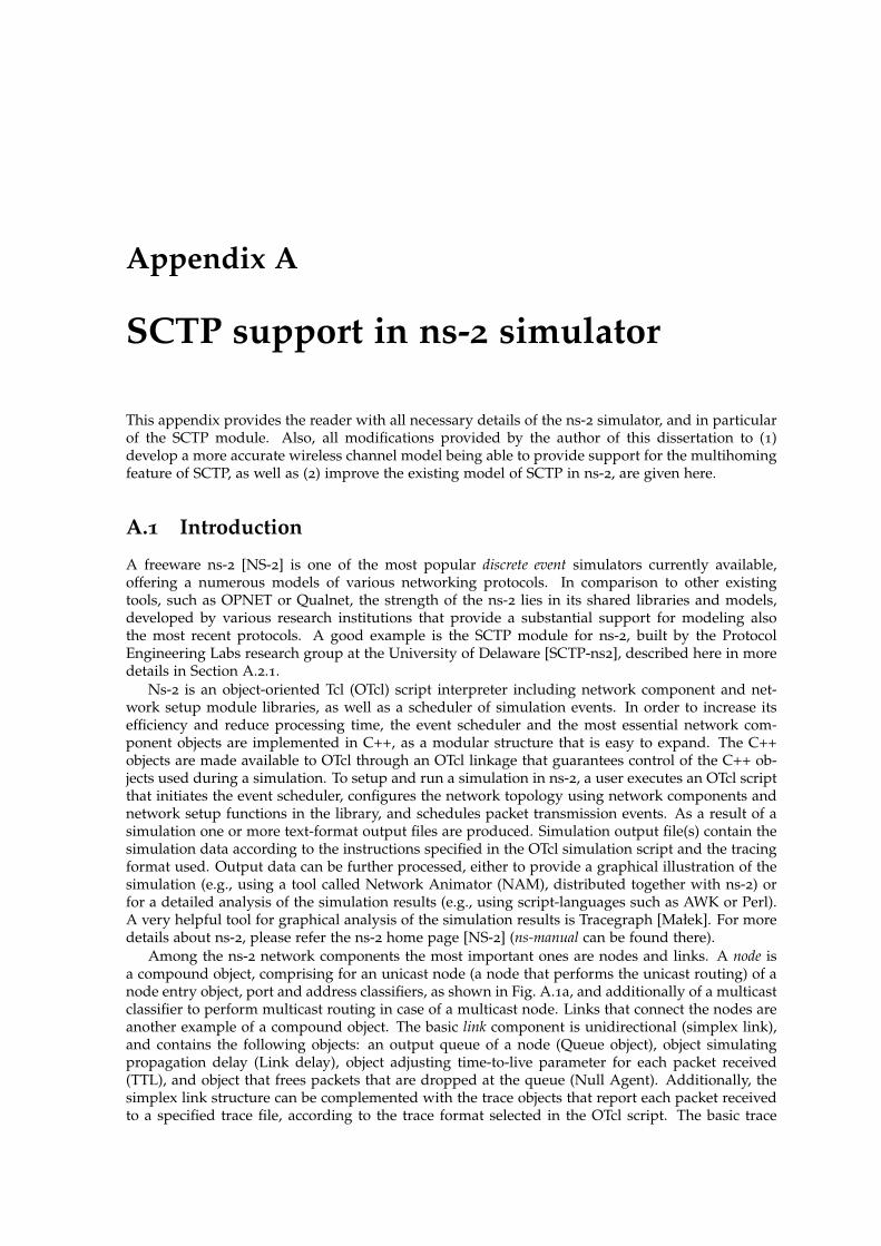
Appendix A
SCTP support in ns-2 simulator
This appendix provides the reader with all necessary details of the ns-2 simulator, and in particularof the SCTP module. Also, all modifications provided by the author of this dissertation to (1)develop a more accurate wireless channel model being able to provide support for the multihomingfeature of SCTP, as well as (2) improve the existing model of SCTP in ns-2, are given here.
A.1 Introduction
A freeware ns-2 [NS-2] is one of the most popular discrete event simulators currently available,offering a numerous models of various networking protocols. In comparison to other existingtools, such as OPNET or Qualnet, the strength of the ns-2 lies in its shared libraries and models,developed by various research institutions that provide a substantial support for modeling alsothe most recent protocols. A good example is the SCTP module for ns-2, built by the ProtocolEngineering Labs research group at the University of Delaware [SCTP-ns2], described here in moredetails in Section A.2.1.
Ns-2 is an object-oriented Tcl (OTcl) script interpreter including network component and net-work setup module libraries, as well as a scheduler of simulation events. In order to increase itsefficiency and reduce processing time, the event scheduler and the most essential network com-ponent objects are implemented in C++, as a modular structure that is easy to expand. The C++objects are made available to OTcl through an OTcl linkage that guarantees control of the C++ ob-jects used during a simulation. To setup and run a simulation in ns-2, a user executes an OTcl scriptthat initiates the event scheduler, configures the network topology using network components andnetwork setup functions in the library, and schedules packet transmission events. As a result of asimulation one or more text-format output files are produced. Simulation output file(s) contain thesimulation data according to the instructions specified in the OTcl simulation script and the tracingformat used. Output data can be further processed, either to provide a graphical illustration of thesimulation (e.g., using a tool called Network Animator (NAM), distributed together with ns-2) orfor a detailed analysis of the simulation results (e.g., using script-languages such as AWK or Perl).A very helpful tool for graphical analysis of the simulation results is Tracegraph [Małek]. For moredetails about ns-2, please refer the ns-2 home page [NS-2] (ns-manual can be found there).
Among the ns-2 network components the most important ones are nodes and links. A node isa compound object, comprising for an unicast node (a node that performs the unicast routing) of anode entry object, port and address classifiers, as shown in Fig. A.1a, and additionally of a multicastclassifier to perform multicast routing in case of a multicast node. Links that connect the nodes areanother example of a compound object. The basic link component is unidirectional (simplex link),and contains the following objects: an output queue of a node (Queue object), object simulatingpropagation delay (Link delay), object adjusting time-to-live parameter for each packet received(TTL), and object that frees packets that are dropped at the queue (Null Agent). Additionally, thesimplex link structure can be complemented with the trace objects that report each packet receivedto a specified trace file, according to the trace format selected in the OTcl script. The basic trace

134 APPENDIX A. SCTP SUPPORT IN NS-2 SIMULATOR
Link
Nodeentry Address
Classifier
PortClassifier
Link
Agent
ApplicationNode
(a)
Node 1simplex link Node1-Node2
Queue
Agent/Null
Node 2
Link entry
drop
TTLEnqT
(-)
DeqT
(+)
RecvT
(r)
DrpT
(d)
Delay
(b)
Figure A.1: Basic network components in ns-2: (a) node; and, (b) link.
objects include: EnqT object reporting arrival of the packet to the queue (marked in the trace formatas ’+’ event), DeqT object tracing the packets leaving the queue (’-’ event), DrpT object followingpackets that were dropped at the queue (’d’ event) and RecvT object that marks the packets correctlyreceived at the end of the link (’r’ event). The entire structure of a simplex link with tracing objectsis shown in Fig. A.1b. In practice, to speed up the topology setup process, the duplex-link functionthat creates two simplex links in both directions between given nodes is used.
The fundamental building blocks to create a protocol stack in ns-2 are agents. Agents representendpoints where network-layer packets are constructed or consumed, and can be extended, usingC++ derived classes, to build additional functionality. On the top of transport agents, e.g., TCP,UDP or SCTP, reside applications. There are two types of applications in ns-2: traffic generators,generating traffic according to a given distribution (e.g., exponential on/off, pareto on/off, constantbit rate (CBR), etc.) and simulated applications, simulating the behavior of a given application.

A.2. IMPLEMENTATION DETAILS 135
Currently there are only two simulated applications available in the main ns-2 distribution: FTPand Telnet.
A.2 Implementation details
This section provides a detailed description of the most important ns-2 simulator modules andobjects that were modified in order to facilitate the simulation support for the analysis presented inthis work.
A.2.1 SCTP module
SCTP module for ns-2 has been developed by the Protocol Engineering Labs at the University ofDelaware [SCTP-ns2]. The first version of a source code has been released as a patch for ns-2 inJuly 2001. Since then, SCTP module has become an integral part of the main ns-2 distribution (fromJanuary 2004), and is subject to periodical updates. The latest version of the source code dates backto July 2007.
The basic functionality of SCTP is provided with the SCTP Agent class (Agent/SCTP). The listof supported features for the current SCTP implementation in ns-2 (release 3.7, version 1.12 of thesctp.cc source code) includes the following sections of the protocol specification (RFC 4960) [Stewart,2007]:
• 5.1 - Normal establishment of an association (rudimentary handshake)• 5.4 - Path verification (only primary path)• 6.1 - Transmission of DATA chunks• 6.2 - Acknowledgement of reception of DATA chunks• 6.3 - Management of retransmission timer• 6.4 - Multihomed SCTP endpoints• 6.5 - Stream Identifier and Stream Sequence Number• 6.6 - Ordered and Unordered Delivery• 6.7 - Report Gaps in received DATA TSNs• 7.2 - SCTP slow-start and congestion avoidance• 8.1 - Endpoint failure detection• 8.2 - Path failure detection• 8.3 - Path HEARTBEAT (without upper layer control)• additionally, there is some support of PR-SCTP, however it is not fully-compliant with RFC
3753 [Manner and Kojo, 2004], as the model was developed already at the draft-stage of thePR-SCTP specification
In context of the ns-2 architecture, multihoming support is the most significant novelty intro-duced by the SCTP module. The ns-2 does not allow creation of nodes with multiple interfaces dueto the limitations posed by the routing algorithm used for wired nodes. Therefore, to provide sup-port for multihomed endpoints with SCTP, the following idea has been applied. Each multihomednode is made of one core node connected via unidirectional links to multiple interface nodes that to-gether form the logical structure of the multihomed node, illustrated in Fig. A.2. The SCTP agentresides on all the nodes that form multihomed node structure, however the data traffic goes onlyfrom and to the interface nodes. The link between the core node and interface nodes is never usedto transmit data, rather for the route lookup only, to dynamically obtain the information which in-terface needs to be used to reach the desired destination. Presented solution for multihomed nodesworks well as far as wired-only scenarios are concerned, however due to the routing issues it cannot be easily extended for the wireless domain, as shown in Section A.2.3.
Some of the functionalities provided by the basic version of the SCTP code, such as the estab-lishment of the association, or path verification procedure are implemented in the limited versionthat needs to be extended if more advanced setup is to be applied. The author of this dissertationproposes the extension of the path verification scheme, to fully fulfil the SCTP RFC 4960 specifi-cation [Stewart, 2007]. Path verification scheme currently implemented in ns-2 provides only theverification of the primary path that is made during the initialization phase of the association. Once

136 APPENDIX A. SCTP SUPPORT IN NS-2 SIMULATOR
the association is set up all paths declared at the association setup are considered active. This is analmost-correct approach, if for most of the simulation time data is sent on the primary path only.However, for the scenarios involving frequent changes of the paths, e.g., handover scenarios thatare subject of the analysis in this dissertation, such situation is not acceptable. Therefore, authorproposes introducing a new variable ePathVerification that controls the path verification setup, andwhich can be bound from within OTcl, with three different values (modes):
/* Variable that controls path verification process*/enum PathVerification_E{
VERIFY_OFF, // no path verification procedure usedVERIFY_ON, // current path verification procedure usedVERIFY_ON_CHANGE, // experimental, path verification is forced
each time when change is performed (handover scenarios, CMT)};
PathVerification_E ePathVerification;// path verification procedure
Simulations presented in this dissertation were performed with ePathVerification set to value:VERIFY ON CHANGE.
Apart from the basic Agent/SCTP class, PEL group provides also several experimental exten-sions to the SCTP, available as separate classes, derived from the basic SCTP’s class. Among pro-vided modifications, two main categories can be distinguished: extensions dedicated to improvethe standard SCTP retransmission policy, and CMT-related extensions. Experimental retransmis-sion policies, described in more details and evaluated in [Caro et al., 2004b], include the followingclasses:
• Agent/SCTP/HbAfterRto - after each RTO, a HEARTBEAT is sent on the destination thattimed out.
• Agent/SCTP/MultipleFastRtx - allows several fsat retransmissions of the same TSN, if neces-sary (Multiple Fast Retransmit algorithm).
Figure A.2: Multihomed node.

A.2. IMPLEMENTATION DETAILS 137
• Agent/SCTP/Timestamp - includes the time stamp into each packet sent, in order to distin-guish original transmissions from retransmissions.
• Agent/SCTP/MfrHbAfterRto - combines MultipleFastRtx and HbAfterRto.• Agent/SCTP/MfrTimestamp - combines MultipleFastRtx and Timestamp.In contrast, all CMT-related functionality is provided within one class Agent/SCTP/CMT. The
latest CMT implementation (release 3.7) includes the following features, explained already in thiswork in Section 5.1.1 on page 84, and described in more detail in [Iyengar et al., 2006]:
• Cwnd Update for CMT algorithm (version 2).• Split Fast Retransmit algorithm.• Delayed Ack for CMT algorithm.• Five CMT-dedicated retransmission policies: RtxCwnd (default and recommended), RtxSsthresh
(recommended), RtxSame (experimental), RtxAsAp (experimental), and RtxLossRate (experi-mental).
• CMT-PF extension [Natarajan et al., 2006].
A.2.2 State of the art for wireless environments and mobility support in ns-2
Wireless support for ns-2 has been first proposed in 1998 in the mobility extension provided by theCMU’s Monarch group [CMU Monarch]. Since then, the wireless functionality has been integratedinto the main ns-2 package. The Monarch’s wireless model introduced the MN object and few addi-tional features to facilitate the simulation of WLANs, multi-hop ad-hoc networks, etc. A MN objectis an extended version of the basic node object. The most important new features are: the ability tomove within given topology while sending/receiving packets, and periodic position updates. Themain difference is that the MN, unlike a basic node, does not need to use the link object to connectto the other nodes. Each MN can have one or more wireless interface, and each interface is attachedto a wireless channel. Packet transmitted by the MN on a given channel is delivered to each inter-face on that channel, and then each interface checks using its radio propagation model whether itwas able to receive given packet. According to the ns-manual [NS-2], the list of the features of thewireless model currently available in the main ns-2 distribution can be summarized according tothe ISO/OSI protocol stack model:
• Physical Layer:– Radio Propagation model - three models available: free space model, two-ray ground
reflection model and shadowing model.– Antenna model - unity gain omni-directional antenna.– Network interface model - a shared media interface, subject to collisions and the propa-
gation model. Each node can overhear packets transmitted by the other nodes.• Link Layer:
– The IEEE 802.11 distributed coordination function (DCF) MAC protocol (for unicastpackets follows the RTS/CTS/DATA/ACK pattern, uses both physical and virtual car-rier sense).
– A single hop, preamble-based TDMA protocol.• Network Layer:
– Four different routing protocols implemented: Dynamic Source Routing (DSR), Destina-tion Sequence Distance Vector (DSDV), Temporally Ordered Routing Protocol (TORA)and Ad-hoc on demand Distance Vector (AODV).
Scope of the application of the original Monarch’s model was limited to the simulation ofWLANs and multihop wireless networks, due to the unsolved routing conflict: wired nodes usetopology-based routing, whereas MNs that do not use links have dedicated routing protocols. Inorder to make possible coexistence of wireless and wired nodes in the same scenario two importantmodifications were introduced. First of them is the base station node (BS), a gateway node that inter-connects the wired and the wireless part of the topology. Second important modification that madepossible routing between wireless and wired domain is hierarchical addressing. Although, originallydevised to reduce the size of the routing tables for large topologies (i.e. topologies with severalthousands of nodes), hierarchical addressing is also useful in a combined wired-wireless scenarios.
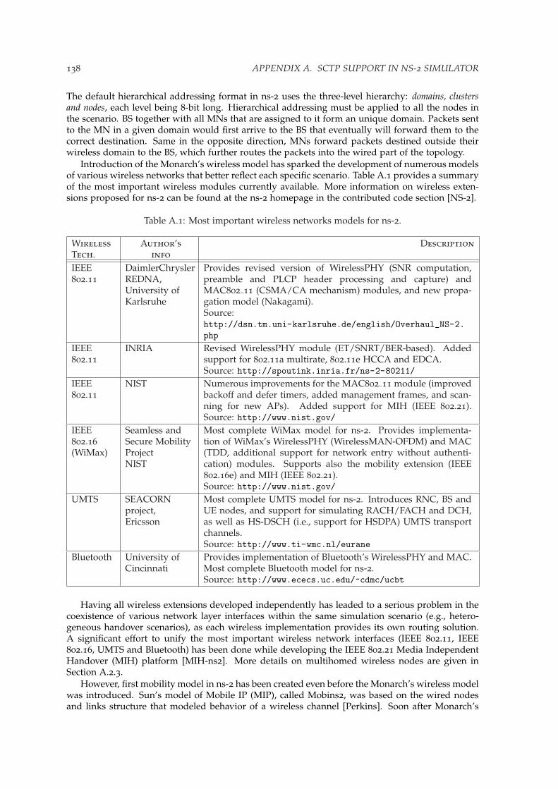
138 APPENDIX A. SCTP SUPPORT IN NS-2 SIMULATOR
The default hierarchical addressing format in ns-2 uses the three-level hierarchy: domains, clustersand nodes, each level being 8-bit long. Hierarchical addressing must be applied to all the nodes inthe scenario. BS together with all MNs that are assigned to it form an unique domain. Packets sentto the MN in a given domain would first arrive to the BS that eventually will forward them to thecorrect destination. Same in the opposite direction, MNs forward packets destined outside theirwireless domain to the BS, which further routes the packets into the wired part of the topology.
Introduction of the Monarch’s wireless model has sparked the development of numerous modelsof various wireless networks that better reflect each specific scenario. Table A.1 provides a summaryof the most important wireless modules currently available. More information on wireless exten-sions proposed for ns-2 can be found at the ns-2 homepage in the contributed code section [NS-2].
Table A.1: Most important wireless networks models for ns-2.
WirelessTech.
Author’sinfo
Description
IEEE802.11
DaimlerChryslerREDNA,University ofKarlsruhe
Provides revised version of WirelessPHY (SNR computation,preamble and PLCP header processing and capture) andMAC802 11 (CSMA/CA mechanism) modules, and new propa-gation model (Nakagami).Source:http://dsn.tm.uni-karlsruhe.de/english/Overhaul_NS-2.php
IEEE802.11
INRIA Revised WirelessPHY module (ET/SNRT/BER-based). Addedsupport for 802.11a multirate, 802.11e HCCA and EDCA.Source: http://spoutink.inria.fr/ns-2-80211/
IEEE802.11
NIST Numerous improvements for the MAC802 11 module (improvedbackoff and defer timers, added management frames, and scan-ning for new APs). Added support for MIH (IEEE 802.21).Source: http://www.nist.gov/
IEEE802.16(WiMax)
Seamless andSecure MobilityProjectNIST
Most complete WiMax model for ns-2. Provides implementa-tion of WiMax’s WirelessPHY (WirelessMAN-OFDM) and MAC(TDD, additional support for network entry without authenti-cation) modules. Supports also the mobility extension (IEEE802.16e) and MIH (IEEE 802.21).Source: http://www.nist.gov/
UMTS SEACORNproject,Ericsson
Most complete UMTS model for ns-2. Introduces RNC, BS andUE nodes, and support for simulating RACH/FACH and DCH,as well as HS-DSCH (i.e., support for HSDPA) UMTS transportchannels.Source: http://www.ti-wmc.nl/eurane
Bluetooth University ofCincinnati
Provides implementation of Bluetooth’s WirelessPHY and MAC.Most complete Bluetooth model for ns-2.Source: http://www.ececs.uc.edu/~cdmc/ucbt
Having all wireless extensions developed independently has leaded to a serious problem in thecoexistence of various network layer interfaces within the same simulation scenario (e.g., hetero-geneous handover scenarios), as each wireless implementation provides its own routing solution.A significant effort to unify the most important wireless network interfaces (IEEE 802.11, IEEE802.16, UMTS and Bluetooth) has been done while developing the IEEE 802.21 Media IndependentHandover (MIH) platform [MIH-ns2]. More details on multihomed wireless nodes are given inSection A.2.3.
However, first mobility model in ns-2 has been created even before the Monarch’s wireless modelwas introduced. Sun’s model of Mobile IP (MIP), called Mobins2, was based on the wired nodesand links structure that modeled behavior of a wireless channel [Perkins]. Soon after Monarch’s

A.2. IMPLEMENTATION DETAILS 139
wireless extension had been announced, Sun’s MIP model was integrated into it, allowing simula-tions of the MIP that use wireless nodes. Currently, the wireless MIP model forms part of the corens-2 distribution. Wireless MIP model introduces MobileNode/MIPMH and MobileNode/MIPBSobjects that are modified versions of MN and BS objects, respectively. MobileNode/MIPBS objectsserve as HA or FA in the wireless MIP scenario, and include the registering agent entity, responsiblefor sending out beacon messages to the MNs, responding to the solicitation messages from MNs,and encapsulating/decapsulating packets when necessary. MobileNode/MIPMH objects used tosimulate MN have also the registering agent, which in this case receives and responds to beaconmessages, as well as sends out solicitations to FA and HA.
The wireless MIP model has already several extensions proposed. The most important in contextof simulations of mobility schemes different than MIP is the No Ad-hoc Routing Agent (NOAH)extension [Widmer]. NOAH is the wireless routing agent dedicated to scenarios where wirelessmultihop routing (e.g., DSDV or DSR) is not desired. NOAH routing does not send any routingrelated packets, and therefore supports only direct communication between the wireless nodes,or between BS nodes and MN nodes. Apart from providing the routing support for non-MIPmobility solutions, the NOAH extension improves also the wireless MIP model. The modificationsinclude support for overlapping service areas of BS and improved handover mechanism through anintelligent selection of FAs.
FHMIP extension [Hsieh], is an example of a mobility extension based on both wireless MIPmodel and NOAH extension that provides models for various mobility management schemes,namely MIP, HMIP, FMIP, and FHMIP. FHMIP extension introduces new type of node, a MAPnode, which is a wired node with the MAP agent. The MAP node acts as an intermediate nodebetween the MN’s HA and current FA. The HA encapsulates packets destined to the MN and sendsthem to the MAP node. The MAP node decapsulates packets incoming from the HA and encap-sulates them again using the FA address. Finally, the FA can decapsulate packets and send themdirectly to the MN. Additionally, FHMIP extension provides support for fast handovers.
Yet, it is important to stress that within the current state-of-the-art of ns-2, the support for non-network-layer-based mobility schemes is not provided.
A.2.3 Multihoming in wireless scenarios
Simulation of multihomed wireless nodes has been one of the most challenging issues for the ns-2community in the recent years. Currently, there are two principal extensions available, offering sup-port for simulations of nodes with multiple wireless interfaces. One of them is the IEEE 802.21 Me-dia Independent Handover (MIH) platform [MIH-ns2], aiming at providing the solution that unifiesrouting algorithm for different wireless interfaces models that were developed independently.
Second important solution is the MIRACLE ns-2 library, developed by the SIGNET Lab at theUniversity of Padova [MIRACLE]. MIRACLE library provides means for the interlayer communica-tion and flexible multi-layer design, allowing not only simulations of wireless nodes with multipleradio interfaces, but also making possible exchange of any type of message/structure/commandamong modules/protocols.
As stated already in Section A.2.1, SCTP multihoming solution was intended to work exclusivelyin the wired networks, due to the wired routing limitations. Indeed, if SCTP multihomed node isused in a mixed wired-wireless scenario with the hierarchical routing, the following routing conflictoccurs, as reported in [Song, 2005]:
num_nodes is set 4INITIALIZE THE LIST xListHeadStarting Simulation...can’t read "Node_(5)": no such element in arraywhile executing"return $Node_($id)"(procedure "_o3" line 3)(Simulator get-node-by-id line 3)invoked from within

140 APPENDIX A. SCTP SUPPORT IN NS-2 SIMULATOR
"$self get-node-by-id [lindex $L 0]"(procedure "_o3" line 14)(Simulator compute-hier-routes line 14)invoked from within"$self compute-hier-routes "invoked from within"if [Simulator hier-addr?] {$self compute-hier-routes} else {$self compute-flat-routes}"(procedure "_o3" line 2)(Simulator compute-routes line 2)invoked from within"[Simulator instance] compute-routes"(procedure "Agent/rtProto/Static" line 2)(Agent/rtProto/Static init-all line 2)invoked from within"Agent/rtProto/Static init-all"invoked from within"if [info exists rtprotos_] {foreach proto [array names rtprotos_] {eval Agent/rtProto/$proto init-all $rtprotos_($proto)}} else {Agent/rtProto/St..."(procedure "_o191" line 3)(RouteLogic configure line 3)invoked from within"[$self get-routelogic] configure"(procedure "_o3" line 5)(Simulator run line 5)invoked from within"$ns_ run"(file "mixed-wired-wireless-sctp.tcl" line 215)
Therefore, there are currently two possible solutions to provide simulations of the SCTP inhandover scenarios: (1) either to adapt the SCTP code, so it can co-operate with one of the multi-homed platforms presented in this section, or (2) to re-use Charlie Perkins’ approach from theinitial MIP implementation [Perkins], and exploit wired nodes and links that fully cooperate withSCTP, to model wireless channels. Author of this dissertation opted to employ the latter option,mainly because of the fact that at the time he started working on his dissertation any of the twomultihome-capable platforms presented here were not yet available.
A.2.4 Proposed solution
In order to supply simulations of SCTP in handover scenarios using wired nodes and links objects,there are several changes that must have been applied to the ns-2 (Section A.3 specifies full list ofthe modified files). A new model of the wireless channel has been provided, based on a modifiedlink model, named ARQLinearErr link, illustrated in Fig. A.3. The most important change lies inadaptation of the link characteristic to that of a wireless link. Therefore, packets arriving at the linkare marked as erroneous in the link delay module, but not dropped. Eventually, packets markedas corrupted are dropped at the drop target of the loss module that is attached after the link delaymodule, so the link delay is applied to all packets, also these corrupted ones. To facilitate packetdrop after the link delay module a special inst-procedure endlink-lossmodel was created.
A.2. IMPLEMENTATION DETAILS 141
Node 1simplex link Node1-Node2
Queue
Agent/Null
Node 2
Link entry
drop
TTLEnqT
(-)DeqT
(+)RecvT
(r)
DrpT(d)
Delay Loss
Figure A.3: Wireless channel model - ARQLinearErr link.
The wireless channel simulated using ARQLinearErr link model is characterized by a constantphysical bit-rate, mean packet error rate (PER) that is either fixed or linearly degrading in functionof time, and number of retransmissions for radio blocks. This model does not deal with radiospecific settings for transmission control, signal-to-noise (SNR), etc.

142 APPENDIX A. SCTP SUPPORT IN NS-2 SIMULATOR
Another important aspects that need to be commented is the construction of the handoverschemes. SCTP code provides primitive set-primary-destination for forcing the primary path changethat can be reused for handover purposes. Using that primitive, simulations for all SCTP-basedhandover schemes described in this dissertation have been provided.
A.3 List of the modified files
The modifications were applied to the following files (all given paths are relative to $NS PATH):
/Makefile/link/delay.cc/link/delay.h/queue/errmodel.cc/queue/errmodel.h/sctp/sctp.cc/sctp/sctp.h/sctp/sctp-cmt.cc/sctp/sctp-cmt.h/tcl/lib/ns-default.tcl/tcl/lib/ns-lib.tcl/tcl/lib/ns-link.tcl

Bibliography
Abd El Al, A., Saadawi, T., and Lee, M. 2004a. Improving throughput and reliability in mobilewireless networks via transport layer bandwidth aggregation. Computer Networks 46, 5 (Decem-ber), 635–649. <83>
Abd El Al, A., Saadawi, T., and Lee, M. 2004b. LS-SCTP: a bandwidth aggregation technique forstream control transmission protocol. Computer Communications 27, 10 (June), 1012–1024. <83>
Abd El Al, A., Saadawi, T., and Lee, M. 2007. Unequal error protection for real-time video inmobile ad hoc networks via multi-path transport. Computer Communications 30, 17 (November),3293–3306. <85>
ACM. The ACM Digital Library. http://portal.acm.org/. <30>
Ahn, B.-H., Kim, D.-Y., Cho, K.-H., Cha, S.-H., and Jo, M. 2007. An efficient resource reservationand qos provisioning mechanism based on mSCTP for next generation network. In The 5th ACISInternational Conference on Software Engineering Research, Management and Applications (SERA 2007).245–252. <39>
Akyildiz, I., Xie, J., and Mohanty, S. 2004. A survey of mobility management in next generationAll-IP based wireless systems. IEEE Wireless Communications 11, 4 (April), 16–28. <1, 8>
Argyriou, A. and Madisetti, V. 2007. The design and evaluation of an end-to-end handoff man-agement protocol. Wireless Networks 13, 1 (February), 61–75. <38>
Atiquzzaman, M. and Reaz, A. 2005. Survey and classification of transport layer mobility man-agement schemes. In The 16th IEEE International Symposium on Personal Indoor and Mobile RadioCommunications (PIMRC 2005). Vol. 4. 2109–2115. <11>
Aydin, I., Seok, W., and Shen, C.-C. 2003. Cellular SCTP: a transport-layer approach to internetmobility. In The 12th International Conference on Computer Communications and Networks (ICCCN2003). 285–290. <39>
Aydin, I. and Shen, C.-C. 2005. Evaluating cellular SCTP over one-hope wireless networks. In The62nd IEEE Vehicular Technology Conference (VTC 2005-Fall). Vol. 2. 826–830. <39>
Bhagwat, P., Perkins, C., and Tripathi, S. 1996. Network layer mobility: an architecture andsurvey. IEEE Personal Communications 3, 3 (June), 54–64. <8>
BibFinder. The BibFinder database. http://kilimanjaro.eas.asu.edu/. <30>
Budzisz, Ł., Ferrus, R., Brunstrom, A., Grinnemo, K.-J. Fracchia, R., Galante, G., and Casade-vall, F. 2008. Towards transport-layer mobility: Evolution of SCTP multihoming. ComputerCommunications 31, 5 (March), 980–998. <37, 38, 39, 88>
Budzisz, Ł., Ferrus, R., and Casadevall, F. 2005. Study on transport layer handover using SCTP.In The 8th International Symposium on Wireless Personal Multimedia Communications (WPMC 2005).1551–1556. <39, 130>
143

144 BIBLIOGRAPHY
Budzisz, Ł., Ferrus, R., and Casadevall, F. 2006a. On the performance of multihoming SCTP indynamically changing radio channels. In The 15th IST Mobile and Wireless Communications Summit.<71>
Budzisz, Ł., Ferrus, R., and Casadevall, F. 2006b. SCTP multihoming performance in dynamicallychanging channels with the influence of link-layer retransmissions. In The 64nd IEEE VehicularTechnology Conference (VTC 2006-Fall). 2624–2628. <38, 79>
Budzisz, Ł., Ferrus, R., and Casadevall, F. 2009. Design principles and performance evaluation ofmSCTP-CMT for transport-layer based handover. In accepted to the 69th IEEE Vehicular TechnologyConference (VTC 2009-Spring). <101>
Budzisz, Ł., Ferrus, R., Casadevall, F., and Amer, P. 2009. On Concurrent Multipath Transfer inSCTP-based handover scenarios. In accepted to the IEEE International Conference on Communications(ICC 2009). <90>
Budzisz, Ł., Ferrus, R., Grinnemo, K.-J., Brunstrom, A., and Casadevall, F. 2007. An analyticalestimation of the failover time in SCTP multihoming scenario. In IEEE Wireless Communicationsand Networking Conference (WCNC 2007). 3932–3937. <54, 55>
Budzisz, Ł., Garcia, J., Brunstrom, A., and Ferrus, R. 2008. A taxonomy and survey of SCTPresearch. work in progress, to be submitted to ACM Computing Surveys. <25, 85>
Bush, R. and Meyer, D. 2002. RFC 3439, some Internet architectural guidelines and philosophy.http://www.ietf.org/rfc/rfc3439.txt. <11>
Campbell, A., Gomez, J., Kim, S., Wan, C.-Y., Turanyi, Z., and Valko, A. 2002. Comparison of IPmicro-mobility protocols. IEEE Wireless Communications 9, 1 (February), 72–82. <9, 11>
Campbell, A., Gomez, J., Wan, C.-Y., Kim, S., Turanyi, Z., and Valko, A. 1999. Cellular IP, IETFdraft. http://tools.ietf.org/id/draft-valko-cellularip-01.txt, draft expired. <9>
Caro, Jr., A. 2005. End-to-end fault tolerance using transport layer multihoming. Ph.D. thesis,University of Delaware. <53, 62, 71, 72, 73>
Caro, Jr., A., Amer, P., and Stewart, R. 2004a. End-to-end failover thresholds for transport layermultihoming. In IEEE Military Communications Conference (MILCOM 2004). 99–105. <62>
Caro, Jr., A., Amer, P., and Stewart, R. 2004b. Retransmission schemes for end-to-end failoverwith transport layer multihoming. In IEEE Global Telecommunications Conference (GLOBECOM2004). Vol. 3. 1341–1347. <136>
Carpenter, B. 1996. RFC 1958, Architectural principles of the Internet.http://www.ietf.org/rfc/rfc1958.txt. <11>
Casetti, C., Chiasserini, C. F., Fracchia, R., and Meo, M. 2006. AISLE: Autonomic Interface Se-LEction for Wireless Users. In International Symposium on a World of Wireless, Mobile and MultimediaNetworks (WoWMoM 2006). 42–48. <39>
Casetti, C., Galante, G., and Greco, R. 2004. Load balancing over multipaths using bandwidth-aware source scheduling. In The 7th International Symposium on Wireless Personal Multimedia Com-munications (WPMC 2004). <85>
Chang, L.-H., Lin, H.-J., and Chang, I. 2007. Dynamic handover mechanism using mobile SCTP incontention based wireless network. In The 5th International Symposium on Parallel and DistributedProcessing and Applications (ISPA 2007). Vol. LNCS 4742. 821–831. <39>
Chang, M., Lee, M., and Koh, S. 2004. Transport layer mobility support utilizing link signalstrength information. IEICE Transactions on Communications E87-B, 9 (September), 2548–2556.<39, 130>
BIBLIOGRAPHY 145
Chockalingam, A., Zorzi, M., and Tralli, V. 1999. Wireless TCP performance with link layerFEC/ARQ. In IEEE International Conference on Communications (ICC 1999). Vol. 2. 1212–1216. <76>
CiteSeer. CiteSeer.IST, Scientific Literature Digital Library. http://citeseer.ist.psu.edu/. <30>
CMU Monarch. The cmu monarch project’s wireless and mobility extensions to ns-2.http://www.monarch.cs.cmu.edu/cmu-ns.html. <137>
Coene, L. 2002. RFC 3257, Stream Control Transmission Protocol applicability statement.http://www.ietf.org/rfc/rfc3257.txt. <17>
Deering, S. and Hinden, R. 1998. RFC 2460, Internet Protocol, version 6 (IPv6) specification.http://www.ietf.org/rfc/rfc2460.txt. <9>
Droms, R., Bound, J., Volz, B., Lemon, T., Perkins, C., and Carney, M. 2003. RFC 3315, DynamicHost Configuration Protocol for IPv6 (DHCPv6). http://www.ietf.org/rfc/rfc3315.txt. <10>
Dutta, A., Famolari, D., Das, S., Ohba, Y., Fajardo, V., Taniuchi, K., Lopez, R., andSchulzrinne, H. 2008. Media-independent pre-authentication supporting secure interdomainhandover optimization. IEEE Wireless Communications 15, 2 (April), 55–64. <7>
Eddy, M. 2004. At what layer does mobility belong? IEEE Communications Magazine 42, 10 (October),155–159. <1, 11, 15>
Eklund, J. and Brunstrom, A. 2006. Impact of SACK delay and link delay on failover performancein SCTP. In The 3rd IASTED International Conference on Communications and Computer Networks.69–74. <68>
El Malki, K. 2007. RFC 4881, Low-latency handoffs in Mobile IPv4.http://www.ietf.org/rfc/rfc4881.txt. <9>
EngVillage. The Engineering Village database. http://www.engineeringvillage2.com/. <30>
Fiore, M. and Casetti, C. 2005. An adaptive transport protocol for balanced multihoming of real-time traffic. In IEEE Global Telecommunications Conference (GLOBECOM 2005). Vol. 2. 1091–1096.<85>
Fiore, M., Casetti, C., and Galante, G. 2007. Concurrent multipath communication for real-timetraffic. Computer Communications 30, 17 (November), 3307–3320. <85>
Fitzpatrick, J., Murphy, S., and Murphy, J. 2006. SCTP based handover mechanism for VoIPover IEEE 802.11b wireless LAN with heterogeneous transmission rates. In IEEE InternationalConference on Communications (ICC 2006). Vol. 5. 2054–2059. <37>
Fogelstroem, E., Jonsson, A., and Perkins, C. 2007. RFC 4857, Mobile IPv4 regional registration.http://www.ietf.org/rfc/rfc4857.txt. <9>
Fracchia, R., Casetti, C., Chiasserini, C.-F., and Meo, M. 2005. A WiSE extension of SCTPfor wireless networks. In IEEE International Conference on Communications, (ICC 2005). 1448–1453.<39>
Fracchia, R., Casetti, C., Chiasserini, C.-F., and Meo, M. 2007. WiSE: Best-path selection inwireless multihoming environments. IEEE Transactions on Mobile Computing 6, 10 (October), 1130–1141. <39>
Fu, S., Ma, L., Atiquzzaman, M., and Lee, Y. 2005. Architecture and performance of SIGMA: Aseamless handover scheme for data networks. In IEEE International Conference on Communications(ICC 2005). Vol. 5. 3249–3255. <13>
Giaretta, G. 2009. Interactions between PMIPv6 and MIPv6: scenarios and related issues, IETFdraft. http://tools.ietf.org/id/draft-ietf-netlmm-mip-interactions-02.txt, work in progress. <7,10>

146 BIBLIOGRAPHY
Goff, T., Moronski, J., Phatak, D., and Gupta, V. 2000. Freeze-TCP: a true end-to-end TCPenhancement mechanism for mobile environments. In The 19th Annual Joint Conference of the IEEEComputer and Communications Society (INFOCOM 2000). 1537–1545. <11>
Goff, T. and Phatak, D. 2004. Unified transport layer support for data striping and host mobility.IEEE Journal on Selected Areas in Communications 22, 4 (May), 737–746. <39, 83, 86>
Google Scholar. Google scholar. http://scholar.google.com/. <30>
Grinnemo, K.-J. and Brunstrom, A. 2005. Impact of traffic load on SCTP failovers in SIGTRAN.In International Conference on Networking 2005 (ICN 2005). 774–783. <65>
Honda, M., Nishida, Y., Nakazawa, J., and Tokuda, H. 2007. Performance enhancement of trans-port layer handover on single-homed mobile nodes. IEICE Transactions on Communications E90-B, 10 (October), 2683–2692. <37, 42, 87>
Hsieh, R. FHMIP ns-2 extension. http://mobqos.ee.unsw.edu.au/robert/opcomm/. <139>
Huang, C.-M., Chiang, M.-S., and Lin, J.-W. 2008. A proactive mobile-initiated fast handoff schemeusing the multihomed approach. Wireless Communications and Mobile Computing. <15>
Huang, C.-M. and Tsai, C. H. 2007. WiMP-SCTP: Multi-path transmission using stream controltransmission protocol (SCTP) in wireless networks. In The 21st International Conference on AdvancedInformation Networking and Applications Workshops/Symposia (AINAW 2007). Vol. 2. 209–214. <86>
Hui, S. and Yeung, K. 2003. Challenges in the migration to 4G mobile systems. IEEE CommunicationsMagazine 41, 12 (December), 54–59. <1>
IEEEXplore. The IEEE Xplore database. http://ieeexplore.ieee.org/Xplore/dynhome.jsp. <30>
IETF SIGTRAN. IETF signaling transport (sigtran) working group webpage. <17, 24>
IETF TSVWG. IETF transport area (tsvwg) working group webpage. <4, 17>
ISI. The ISI Web of Knowledge. http://www.isiwebofknowledge.com/. <30>
Iyengar, J., Amer, P., and Stewart, R. 2004a. Concurrent multipath transfer using transport layermultihoming - performance under varying bandwidth proportions. In IEEE Military Communica-tions Conference (MILCOM 2004). 238–244. <84>
Iyengar, J., Amer, P., and Stewart, R. 2004b. Retransmission policies for concurrent multipathtransfer using SCTP multihoming. In The 12th IEEE International Conference on Networks (ICON2004). 713–719. <84, 97>
Iyengar, J., Amer, P., and Stewart, R. 2005. Receive buffer blocking in concurrent multipathtransfer. In IEEE Global Telecommunications Conference (GLOBECOM 2005). Vol. 1. 121–126. <84>
Iyengar, J., Amer, P., and Stewart, R. 2006. Concurrent multipath transfer using sctp multihomingover independent end-to-end paths. IEEE/ACM Transactions on Networking 14, 5 (October), 951–964. <24, 49, 84, 97, 99, 137>
Iyengar, J., Amer, P., and Stewart, R. 2007. Performance implications of a bounded receive bufferin concurrent multipath transfer. Computer Communications 30, 4 (February), 818–829. <85>
Johnson, D. and Perkins, C. 2001. Route optimization in Mobile IP, IETF draft.http://tools.ietf.org/id/draft-ietf-mobileip-optim-11.txt, draft expired. <9>
Johnson, D., Perkins, C., and Arkko, J. 2004. RFC 3775, Mobility support in IPv6.http://www.ietf.org/rfc/rfc3775.txt. <9, 109>
Jung, H., Koh, S., Soliman, H., and et al. 2004. Fast handover for Hierarchical MIPv6 (F-HMIPv6), IETF draft. http://tools.ietf.org/id/draft-jung-mobileip-fastho-hmipv6-04.txt, draftexpired. <10>
BIBLIOGRAPHY 147
Jungmaier, A., Rathgeb, E., and Tuexen, M. 2002. On the use of SCTP in failover scenarios. In The6th World Multiconference on Systemics, Cybernetics, and Informatics (SCI 2002). 363–368. <65>
Kashihara, S., Iida, K., Koga, H., Kadobayashi, Y., and Yamaguchi, S. 2004. Multi-path transmis-sion algorithm for end-to-end seamless handover across heterogeneous wireless access networks.IEICE Transactions on Communications E87-B, 3 (March), 490–496. <39, 68>
Kim, D., Koh, S., and Kim, S. 2006. mSCTP-DAC: dynamic address configuration for msctp han-dover. In International Conference on Embedded and Ubiquitous Computing (EUC 2006). Vol. LNCS4096. 244–253. <39>
Kim, W., Kim, M., Lee, K., Yu, C., and Lee, B. 2004. Link layer-assisted mobility support usingSIP for real-time multimedia communications. In The 2nd ACM International Workshop on MobilityManagement and Wireless Access Protocols (MobiWac 2004). 127–129. <14>
Koh, S., Chang, M. J., and Lee, M. 2004. mSCTP for soft handover in transport layer. IEEECommunications Letters 8, 3 (March), 189–191. <38, 39>
Koh, S. and Xie, Q. 2004. Mobile SCTP with Mobile IP for transport layer mobility, IETF draft.http://tools.ietf.org/id/draft-sjkoh-mobile-sctp-mobileip-04.txt, draft expired. <14>
Koh, S. and Xie, Q. 2005. Mobile SCTP (mSCTP) for IP handover support, IETF draft.http://tools.ietf.org/id/draft-sjkoh-msctp-01.txt, draft expired. <24, 25>
Kohler, E., Handley, M., and Floyd, S. 2006. RFC 4340, Datagram Congestion Control Protocol(DCCP). http://www.ietf.org/rfc/rfc4340.txt. <11>
Kong, K.-S., Lee, W., Han, Y.-H., Shin, M.-K., and You, H. 2008. Mobility management for all-IPmobile networks: mobile IPv6 vs. proxy mobile IPv6. IEEE Wireless Communications 15, 2 (April),36–45. <10>
Koodli, R. 2008. RFC 5268, Mobile IPv6 fast handovers. http://www.ietf.org/rfc/rfc5268.txt. <10>
Koodli, R. and Perkins, C. 2007. RFC 4988, Mobile IPv4 fast handovers.http://www.ietf.org/rfc/rfc4988.txt. <9>
Lee, K. J., Nam, S. S., and Mun, B. I. 2006. Sctp efficient flow control during handover. In IEEEWireless Communications and Networking Conference (WCNC 2006). 69–73. <39>
Liebsch, M., Singh, A., Chaskar, H., Funato, D., and Tuexen, M. 2005. RFC 4066, CandidateAccess Router Discovery (CARD). http://www.ietf.org/rfc/rfc4066.txt. <42>
Ma, L., Yu, F., and Leung, V. 2007. Performance improvements of mobile SCTP in integratedheterogeneous wireless networks. IEEE Transactions on Wireless Communications 6, 10 (October),3567–3577. <39>
Ma, L., Yu, F., Leung, V., and Randhawa, T. 2004. A new method to support UMTS/WLANvertical handover using sctp. IEEE Wireless Communications 11, 4 (August), 44–51. <38>
Małek, J. Tracegraph tool (ns trace file analyzer). http://www.tracegraph.com/. <133>
Maltz, D. and Bhagwat, P. 1998. MSOCKS: an architecture for transport layer mobility. In The 17thAnnual Joint Conference of the IEEE Computer and Communications Society (INFOCOM 1998). Vol. 3.1037–1045. <11>
Manner, J. and Kojo, M. 2004. RFC 3753, Mobility related terminology.http://www.ietf.org/rfc/rfc3753.txt. <5, 39, 135>
Matsuoka, H., Yoshimura, T., and Ohya, T. 2003. End-to-end robust IP soft handover. In IEEEInternational Conference on Communications (ICC 2003). Vol. 1. 532–536. <13>

148 BIBLIOGRAPHY
MIH-ns2. The network simulator ns-2 NIST add-on: IEEE 802.21 model. http://www.nist.gov/.<138, 139>
MIRACLE. NS-MIRACLE library: the Multi-InteRfAce Cross-Layer Extension for ns-2 simulator.http://www.dei.unipd.it/wdyn/?IDsezione=3965. <139>
Mockapetris, P. 1987. RFC 1034, Domain names - concepts and facilities.http://www.ietf.org/rfc/rfc1034.txt. <11>
Montenegro, G. 2001. RFC 3024, Reverse tunneling for Mobile IP, revised.http://www.ietf.org/rfc/rfc3024.txt. <9>
Natarajan, P., Ekiz, N., Amer, P., and Stewart, R. 2009. Concurrent multipath transfer duringpath failure. accepted for publication in Computer Communications 32. <85, 110>
Natarajan, P., Iyengar, J., Amer, P., and Stewart, R. 2006. Concurrent multipath transfer usingtransport layer multihoming: Performance under network failures. In IEEE Military Communica-tions Conference (MILCOM 2006). <85, 110, 112, 137>
Nikander, P., Arkko, J., Aura, T., Montenegro, G., and Nordmark, E. 2005. RFC 4225, MobileIPv6 route optimization security design background. http://www.ietf.org/rfc/rfc4225.txt. <9>
Noonan, J., Perry, P., and Murphy, J. 2002. A study of SCTP services in mobile IP network. InThe 2nd Annual Information Technology and Telecommunications Conference (ICT 2002). 153–161. <14,131>
Noonan, J., Perry, P., and Murphy, J. 2006. End-point synchronisation and handover for multi-homed services. IEE Proceedings: Communications 153, 5 (October), 691–696. <39>
NS-2. The network simulator ns-2. http://www.isi.edu/nsnam/ns/. <3, 4, 59, 71, 89, 133, 137,138>
Ong, L., Rytina, I., Garcia, M., Schwarzbauer, H., Coene, L., Lin, H., Juhasz,I., and Sharp, C. 1999. RFC 2719, Framework architecture for signaling transport.http://www.ietf.org/rfc/rfc2719.txt. <17>
Paxon, V. and Allman, M. 2000. RFC 2988, Computing TCPs retransmission timer.http://www.ietf.org/rfc/rfc2988.txt. <51>
Paxon, V., Allman, M., and Stevens, W. 1999. RFC 2581, TCPs congestion control.http://www.ietf.org/rfc/rfc2581.txt. <22, 68>
Perkins, C. Mobins2 extension to ns-2. http://people.nokia.net/ charliep/mobins2/. <138, 140>
Perkins, C. 1997. Mobile IP. IEEE Communications Magazine 35, 5 (May), 84–99. <8>
Perkins, C. 2002. RFC 3344, IP mobility support for IPv4. http://www.ietf.org/rfc/rfc3344.txt. <2,8, 109>
Perkins, C., Calhoun, P., and Bharatia, J. 2007. RFC 4721, Mobile IPv4 challenge/responseextensions (revised). http://www.ietf.org/rfc/rfc4721.txt. <9>
Perkins, C. and Johnson, D. 1998. Route optimization for Mobile IP. Cluster Computing 1, 2 (June),161–176. <9, 109>
Perotto, F., Casetti, C., and Galante, G. 2007. SCTP-based transport protocols for concurrentmultipath transfer. In IEEE Wireless Communications and Networking Conference (WCNC 2007).2971–2976. <85>
Plummer, D. 1982. RFC 826, An Ethernet Address Resolution Protocol: Or converting networkprotocol addresses to 48.bit Ethernet address for transmission on Ethernet hardware, (standard37). http://www.ietf.org/rfc/rfc826.txt. <8>
BIBLIOGRAPHY 149
Postel, J. 1980. RFC 768, User Datagram Protocol, (standard 6). http://www.ietf.org/rfc/rfc768.txt.<2>
Postel, J. 1981. RFC 793, Transmission Control Protocol, (standard 7).http://www.ietf.org/rfc/rfc793.txt. <2>
Postel, J. 1984. RFC 925, Multi-LAN address resolution. http://www.ietf.org/rfc/rfc925.txt. <8>
Ramjee, R., La Porta, T., Thuel, S., Varadhan, K., and Wang, S. 1999. HAWAII: a domain-basedapproach for supporting mobility in wide-area wireless networks. In Proc. of the 7th InternationalConference on Network Protocols (ICNP 1999). 283–292. <9>
Riegel, M. and Tuexen, M. 2007. Mobile SCTP, IETF draft. http://tools.ietf.org/id/draft-riegel-tuexen-mobile-sctp-09.txt, work in progress. <7, 11, 25>
Rosenberg, J., Schulzrinne, H., Camarillo, G., Johnston, A., Peterson, J., Sparks,R., Handley, M., and Schooler, E. 2002. RFC 3261, SIP: Session Initiation Protocol.http://www.ietf.org/rfc/rfc3261.txt. <14>
Rossi, C., Casetti, C., Fiore, M., and Schonfeld, D. 2006. A partially reliable transport protocolfor multiple-description real-time multimedia traffic. In The 2006 IEEE International Conference onImage Processing. 1301–1304. <85>
Saha, D., Mukherjee, A., Misra, I., Chakraborty, M., and Subhash, N. 2004. Mobility supportin IP: a survey of related protocols. IEEE Network 18, 6 (November-December), 34–40. <11, 112,113>
Schulzrinne, H. and Wedlund, E. 2000. Application-layer mobility using SIP. ACM Mobile Com-puter and Communications Review 4, 3 (July), 47–57. <14>
SCTP-FreeBSD. SCTP reference implementation. http://www.sctp.org/. <41, 54, 107>
SCTP-LK. Linux kernel SCTP (LK-SCTP) implementation. http://lksctp.sourceforge.net/. <37,54>
SCTP-ns2. Protocol engineering labs (pel), SCTP module for network simulator ns-2.http://pel.cis.udel.edu/. <4, 31, 34, 131, 133, 135>
SCTP-Qualnet. SCTP module for Qualnet simulator. http://degas.cis.udel.edu/SCTP/. <4, 31>
SCTP-SS7. Open SS7 SCTP implementation. http://www.openss7.org/. <54>
SCTP Survey. SCTP Database webpage. http://www.cs.kau.se/cs/prtp/sctpwiki/pmwiki.php?n=Resources.SCTPSurvey. <30>
Shacham, R., Schulzrinne, H., Thakolsri, S., and Kellerer, W. 2007. Session Initiation Pro-tocol (SIP) session mobility, IETF draft. http://tools.ietf.org/id/draft-shacham-sipping-session-mobility-05.txt, RFC Ed Queue. <14>
Snoeren, A. and Balakrishnan, H. 2000. An end-to-end approach to host mobility. In The 6thInternational Conference on Mobile Computing and Networking (MobiCom 2000). 155–166. <13>
Soliman, H., Castelluccia, C., El Malki, K., and Bellier, L. 2005. RFC 4140, Hierarchical MobileIPv6 mobility management (HMIPv6). http://www.ietf.org/rfc/rfc4140.txt. <10>
Song, J. 2005. Performance evaluation of handoff between UMTS/802.11b based on Mobile IP andSCTP. M.S. thesis, North Carolina State University. <139>
Stewart, R. 2007. RFC 4960, Stream Control Transmission Protocol (SCTP).http://www.ietf.org/rfc/rfc4960.txt. <17, 18, 19, 22, 23, 53, 54, 71, 135>
Stewart, R. and Amer, P. 2007. Why is SCTP needed given TCP and UDP are widely available?http://www.isoc.org/briefings/017/. <25>
150 BIBLIOGRAPHY
Stewart, R., Arias-Rodriguez, I., Poon, K., Caro, Jr., A., and Tuexen, M. 2006.RFC 4460, Stream Control Transmission Protocol (SCTP) specification errata and issues.http://www.ietf.org/rfc/rfc4460.txt. <17>
Stewart, R., Ramalho, M., Xie, Q., Tuexen, M., and Conrad, P. 2004. RFC 3758, Stream ControlTransmission Protocol (SCTP) partial reliability extension. http://www.ietf.org/rfc/rfc3758.txt.<17, 19, 24, 25>
Stewart, R., Tuexen, M., and Camarillo, G. 2007. RFC 5062, Security attacks foundagainst the Stream Control Transmission Protocol (SCTP) and current countermeasures.http://www.ietf.org/rfc/rfc5062.txt. <13, 24, 42, 131>
Stewart, R., Tuexen, M., and Ruengeler, I. 2008. SCTP Network Address Translation, IETF draft.http://tools.ietf.org/id/draft-ietf-behave-sctpnat-00.txt, work in progress. <38>
Stewart, R. and Xie, Q. 1998. Multi-network Datagram Transmission Protocol (MDTP), IETF draft.http://tools.ietf.org/id/draft-stewart-xie-mdtp-00.txt, draft expired. <17>
Stewart, R. and Xie, Q. 2001. Stream Control Transmission Protocol (SCTP) - A reference guide. AddisonWesley. <53>
Stewart, R., Xie, Q., Morneault, K., Sharp, C., Schwarzbauer, H., Taylor, T., Rytina, I., Kalla,M., Zhang, L., and Paxson, V. 2000. RFC 2960, Stream Control Transmission Protocol (SCTP).http://www.ietf.org/rfc/rfc2960.txt, obsoleted by RFC 4960. <17, 23>
Stewart, R., Xie, Q., Tuexen, M., Maruyama, S., and Kozuka, M. 2007. RFC5061, Stream Control Transmission Protocol (SCTP) Dynamic Address Reconfiguration.http://www.ietf.org/rfc/rfc5061.txt. <19, 24, 42, 130>
Stone, J., Stewart, R., and Otis, D. 2002. RFC 3309, Stream Control Transmission Protocol (SCTP)checksum change. http://www.ietf.org/rfc/rfc3309.txt, obsoleted by RFC 4960. <17>
Thomson, S. and Narten, T. 1998. RFC 2462, IPv6 stateless address autoconfiguration.http://www.ietf.org/rfc/rfc2462.txt. <10>
Tuexen, M., Stewart, R., Lei, P., and Rescorla, E. 2007. RFC 4895, Authenticated chunks forthe Stream Control Transmission Protocol (SCTP). http://www.ietf.org/rfc/rfc4895.txt. <19, 25,131>
Vacirca, F., De Vebductis, A., and Baiocchi, A. 2006. Optimal design of hybrid FEC/ARQschemes for TCP over wireless links with Rayleigh fading. IEEE Transactions on Mobile Com-puting 5, 4 (April), 289–302. <76>
Vakil, F., Dutta, A., Chen, J.-C., Tauil, M., Baba, S., Nakajima, N., and Schulzrinne, H. 2001.Supporting mobility for TCP with SIP, IETF draft. http://tools.ietf.org/id/draft-itsumo-sipping-mobility-tcp-00.txt, draft expired. <14>
Vixie, P., Thomson, S., Rekhter, Y., and Bound, J. 1997. RFC 2136, Dynamic updates in the DomainName System (DNS UPDATE). http://www.ietf.org/rfc/rfc2136.txt. <11>
Wedlund, E. and Schulzrinne, H. 1999. Mobility support using SIP. In The 2nd ACM InternationalWorkshop on Wireless Mobile Multimedia (WoWMoM 1999). 76–82. <14>
Widmer, J. No Ad-hoc Routing Agent (NOAH) extension for ns-2.http://icapeople.epfl.ch/widmer/uwb/ns-2/noah. <139>
Xie, Q., Stewart, R., Holdrege, M., and Tuexen, M. 2007. SCTP NAT Traversal Considerations,IETF draft. http://tools.ietf.org/id/draft-xie-behave-sctp-nat-cons-03.txt, draft expired. <38>
Yabusaki, M., Okagawa, T., and Imai, K. 2005. Mobility management in All-IP mobile network:end-to-end intelligence or network intelligence? IEEE Communications Magazine 43, 12 (Decem-ber), supl.16–supl.24. <1, 10>

BIBLIOGRAPHY 151
Ye, G., Saadawi, T., and Lee, M. 2004. IPCC-SCTP: an enhancement to the standard SCTP to sup-port multi-homing efficiently. In The 23rd IEEE International Conference on Performance, Computing,and Communications (IPCCC 2004). 523–530. <83>
Zahran, A., Liang, B., and Saleh, A. 2008. Mobility modeling and performance evaluation ofheterogeneous wireless networks. IEEE Transactions on Mobile Computing 7, 8 (August), 1041–1056.<110>
Zeadally, S. and Siddiqui, F. 2007. An empirical analysis of handoff performance for SIP, mobileIP, and SCTP protocols. Wireless Personal Communications 43, 2 (October), 589–603. <38>
Zhang, J., Chan, H., and Leung, V. 2007. A SIP-based seamless-handoff (S-SIP) scheme for het-erogeneous mobile networks. In IEEE Wireless Communications and Networking Conference (WCNC2007). 3946–3950. <15>
Zimmermann, H. 1980. OSI reference model–the ISO model of architecture for open systems inter-connection. IEEE Transactions on Communications [legacy, pre - 1988] 28, 4 (April), 425–432. <1>
References in this dissertation follow the ACM Transactions bibliography style: in-text citations have the general form”[author name(s) year]”, whereas the reference list is sorted alphabetically by the author name(s). Page(s) where the item isreferenced are given in angle brackets <p.>.
Index
. . . . . . . . . . . . . . . . . . . . . . . . . . . . . . . . . . . . . . . . . . . . . . . . . . . . . . . A
access network (AN), 6access network gateway (ANG), 6access point (AP), 6, 39–44access router (AR), 6, 39
new access router (NAR), 6old access router (OAR), 6
additive increase multiplicative decrease (AIMD), 22administrative domain (AD), 6appropriate byte counting (ABC), 107ASCONF, see SCTP DAR extensionASCONF-ACK, see SCTP DAR extension
. . . . . . . . . . . . . . . . . . . . . . . . . . . . . . . . . . . . . . . . . . . . . . . . . . . . . . . .B
bandwidth delay product (BDP), 59, 61base station (BS), 6Beyond 3G (B3G), 1
. . . . . . . . . . . . . . . . . . . . . . . . . . . . . . . . . . . . . . . . . . . . . . . . . . . . . . . .C
Cellular IP, see Mobile IP extensionsConcurrent Multipath Transfer (CMT), 2, 49, 68, 84
cwnd update for CMT (CUC), 84delayed ACK for CMT (DAC), 84drawbacks, 84–85
receiver buffer (rbuf) blocking, 84, 95, 101–104,108, 115–117
mobility application, see mSCTP-CMTPF extension, 85, 86, 108, 112retransmission policy, 84, 97–101split fast retransmit (SFR), 84
congestion avoidance, 22congestion window (cwnd), 22correspondent node (CN), 6, 42–49, 87Cumulative TSN ACK Point (CumTSN), 22, 84, 85, 107
. . . . . . . . . . . . . . . . . . . . . . . . . . . . . . . . . . . . . . . . . . . . . . . . . . . . . . . D
Dynamic Address Reconfiguration (DAR) SCTP exten-sion, see SCTP DAR extension
Dynamic Domain Name System (DDNS), 11
. . . . . . . . . . . . . . . . . . . . . . . . . . . . . . . . . . . . . . . . . . . . . . . . . . . . . . . . F
failover, see SCTP failover mechanismFast Handovers for HMIPv6 (F-HMIPv6), see Mobile IPv6
extensionsFast Handovers for Mobile IP (FMIP), see Mobile IP ex-
tensionsFast Handovers for Mobile IPv6 (FMIPv6), see Mobile
IPv6 extensionsfast recovery, 22fast retransmission, 22, 84, 97, 117
spurious retransmission, 79, 80, 84
. . . . . . . . . . . . . . . . . . . . . . . . . . . . . . . . . . . . . . . . . . . . . . . . . . . . . . . G
Global System for Mobile Communications/General PacketRadio Service (GSM/GPRS), 1, 29, 39, 59
. . . . . . . . . . . . . . . . . . . . . . . . . . . . . . . . . . . . . . . . . . . . . . . . . . . . . . . H
Hawaii, see Mobile IP extensionshead-of-line (HoL) blocking problem, 17, 24Hierarchical Mobile IP (HMIP), see Mobile IP extensionsHierarchical Mobile IPv6 (HMIPv6), see Mobile IPv6 ex-
tensions
. . . . . . . . . . . . . . . . . . . . . . . . . . . . . . . . . . . . . . . . . . . . . . . . . . . . . . . . I
Internet Protocol (IP), 1, 61ISO/OSI model, 1
. . . . . . . . . . . . . . . . . . . . . . . . . . . . . . . . . . . . . . . . . . . . . . . . . . . . . . . . L
link-layer retransmissions, 76–80automatic repeat request (ARQ), 76forward error correction (FEC), 76
loadsharingtransport-layer loadsharing, 2, 23, 83
SCTP-based loadsharing, see SCTP loadsharingLow-latency Mobile IP, see Mobile IP extensions
. . . . . . . . . . . . . . . . . . . . . . . . . . . . . . . . . . . . . . . . . . . . . . . . . . . . . . . M
maximum transmission unit (MTU), 19, 22, 97, 107mobile host (MH), see mobile nodeMobile IP (MIP), 2, 8–9, 11, 37, 38, 112–113, 130
care-of address, 8extensions, 9, 11, 112–113, 130foreign agent, 8home address, 8home agent, 8IP tunneling, 8route optimization (MIP-RO), 9triangular routing, 9
Mobile IPv4 (MIPv4), see Mobile IPMobile IPv6 (MIPv6), 9–10, 11, 113, 130
extensions, 10, 11mobile node (MN), 6, 40–49, 86, 110
multi-homed, 42–49, 87single-homed, 40–42, 87
mobile Stream Control Transmission Protocol (mSCTP),1, 13–14, 24–25, 34–49, 88, 91, 111, 130
address manipulation, 25, 41–44handover policy, 37–38, 39, 42–49, 61, 88, 91, 111link-layer support, 39, 44, 130open points, 37, 130use cases, 39–49
mobility management, 5–6, 6–7, 7–15application layer schemes, 14–15, 15
SIP, see Session Initiation Protocol (SIP)
152

INDEX 153
network layer schemes, 8–11, 15Mobile IP, see Mobile IP
personal mobility, 6service mobility, 7session mobility, 7sub-network layer mobility, 8terminal mobility, 6
global mobility, 7handover management, 7–8local mobility, 7location management, 7
transport layer schemes, 11–14, 15complete-mobility schemes (mobility managers),
13connection-migration protocols, 11gateway-based mobility schemes, 11handover protocols, 13mSCTP, see mobile Stream Control Transmission
Protocol (mSCTP)mSCTP-CMT, 2, 86–87, 87–89, 91, 108, 112, 130
analytical model, 89–90improvements, 107–108parameters, 88–89
bandwidth ratio, 89, 89–95, 115–117delta, 110, 117–122dwelling time, 88, 89–95, 115–117
rbuf blocking, see Concurrent Multipath Transfer(CMT) drawbacks receiver buffer (rbuf) block-ing
smooth transition between the paths, 95–97Multi-network Datagram Transmission Protocol (MDTP),
17
. . . . . . . . . . . . . . . . . . . . . . . . . . . . . . . . . . . . . . . . . . . . . . . . . . . . . . . N
ns-2 network simulator, 3, 4, 71, 133–142radio channel model, 113, 131, 140–142SCTP module, 31, 34, 131, 135–137
CMT implementation, 89, 137tracing, 99–101, 133–134wireless node, 137–139
multihomed wireless node, 131, 139–140
. . . . . . . . . . . . . . . . . . . . . . . . . . . . . . . . . . . . . . . . . . . . . . . . . . . . . . . . P
packet error rate (PER), 61, 71partial bytes acked, 22Path.Max.Retrans (PMR), see SCTP parameters PMRpoint of attachment (PoA), 6, 40Proxy MIPv6 (PMIPv6), see Mobile IPv6 extensions
. . . . . . . . . . . . . . . . . . . . . . . . . . . . . . . . . . . . . . . . . . . . . . . . . . . . . . . Q
Qualnet network simulatorSCTP module, 31
. . . . . . . . . . . . . . . . . . . . . . . . . . . . . . . . . . . . . . . . . . . . . . . . . . . . . . . .R
radio access network (RAN), 1, 86–88, 110retransmission timeout (RTO), 22, 42, 53–54, 79, 108, 122
exponential back-off, 53lower bound (RTO.Min), see SCTP parameters RTO.Minping-pong effect, 62spurious timeout (or failover), 62, 65, 73, 97–101upper bound (RTO.Max), see SCTP parameters RTO.Max
round-trip time (RTT), 22, 55, 65–68, 85, 101–104
. . . . . . . . . . . . . . . . . . . . . . . . . . . . . . . . . . . . . . . . . . . . . . . . . . . . . . . . S
Session Initiation Protocol (SIP), 14–15, 28, 37, 38architecture, 14–15
slow start, 22slow-start threshold (ssthresh), 22Stream Control Transmission Protocol (SCTP), 17–24, 25,
129–130alternate path, 23backup path, see SCTP alternate pathchunk, 18–19congestion control, 22, 27, 34DAR extension, 2, 24–25, 27, 34, 37failover mechanism, 2, 24, 38–39, 44–49, 51–54, 61–
80, 87–88, 91, 111, 130failover time estimation, 54–59
heartbeat, 25, 44, 51, 68, 85, 87, 108loadsharing, 2, 24, 34, 49, 68, 83–85, 85, 130
CMT, see Concurrent Multipath Transfer (CMT)independent per path congestion control SCTP
(IPCC-SCTP), 83LS-SCTP, 83scheduling algorithms, 85Westwood SCTP (W-SCTP), 85
multihoming, 1, 23–24, 26–27, 30–31, 34–37, 42–49,83–85, 87–88
multistreaming, 24, 27, 34parameters
PMR, 38, 51, 53–56, 59, 62–65, 73–76, 80, 85, 87–88,108
Heartbeat.Interval, 51, 68RTO.Max, 53RTO.Min, 38, 53, 65–68, 80, 87–88SACK.delay, 56, 68cwnd.init, 22recommended settings, 71
PR-SCTP extension, 24, 25, 27, 85primary path, 23, 23–25, 41–44, 51–54retransmission policy, 24, 39, 71taxonomy, 25–30
stream sequence number (SSN), 24
. . . . . . . . . . . . . . . . . . . . . . . . . . . . . . . . . . . . . . . . . . . . . . . . . . . . . . . .T
T3-rtx timer, 51–53, 57expiration, see retransmission timeout (RTO)
TCP-friendliness, 84, 87transmission sequence number (TSN), 22Transport Control Protocol (TCP), 2, 11, 19–22, 25, 68, 130
. . . . . . . . . . . . . . . . . . . . . . . . . . . . . . . . . . . . . . . . . . . . . . . . . . . . . . . U
Universal Mobile Telecommunications System (UMTS), 1,29, 39, 59, 117
User Datagram Protocol (UDP), 2, 11, 25, 130
. . . . . . . . . . . . . . . . . . . . . . . . . . . . . . . . . . . . . . . . . . . . . . . . . . . . . . . W
wireless local area network (WLAN), 1, 28, 39, 59, 117


![A cost-effective SCTP extension for hybrid vehicular networksepubs.surrey.ac.uk/813945/1/ce-sctp-paper.pdf · Stream Control Transmission Protocol (SCTP) [21] is an IETF standard,](https://img.dokumen.tips/doc/110x75/5e749c4587e5a705651d86e6/a-cost-effective-sctp-extension-for-hybrid-vehicular-stream-control-transmission.jpg)