Embed Size (px)
Citation preview
Beam Diagnostics Using Synchrotron Radiation:
Theory and PracticeUS Particle Accelerator School
University of California, Santa Cruz
San Francisco — 2010 January 18 to 22
Streak Camera & Gated Camera Lab Primer
Jeff Corbetta, Alan Fishera, Walter Moka, Weixing Chengb
a - SLAC National Accelerator Laboratoryb - Brookhaven National Laboratory
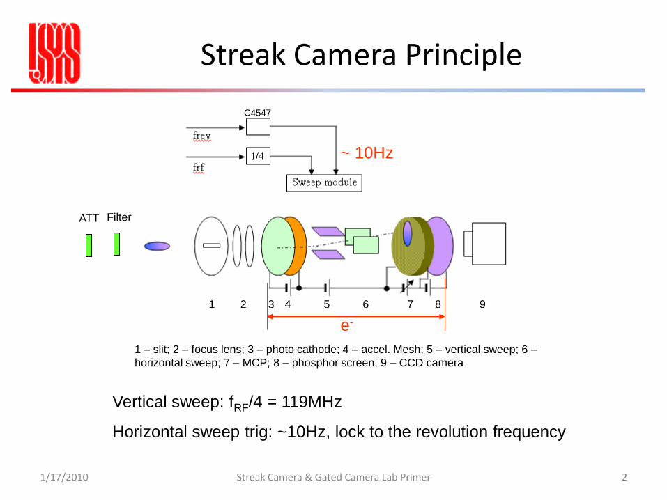
Streak Camera Principle
1/17/2010 2Streak Camera & Gated Camera Lab Primer
~ 10Hz
Vertical sweep: fRF/4 = 119MHz
Horizontal sweep trig: ~10Hz, lock to the revolution frequency
C4547
1 2 3 4 5 6 7 8 9
1 – slit; 2 – focus lens; 3 – photo cathode; 4 – accel. Mesh; 5 – vertical sweep; 6 –
horizontal sweep; 7 – MCP; 8 – phosphor screen; 9 – CCD camera
e-
ATT Filter
0 0.5 1 1.5 2 2.5 3 3.5 4 4.5 5-1
-0.5
0
0.5
1
t (1/Frf)
Vrf
(M
V)
0 0.5 1 1.5 2 2.5 3 3.5 4 4.5 5-1
-0.5
0
0.5
1
t (1/Frf)
Vsw
eep (
a.u
.)
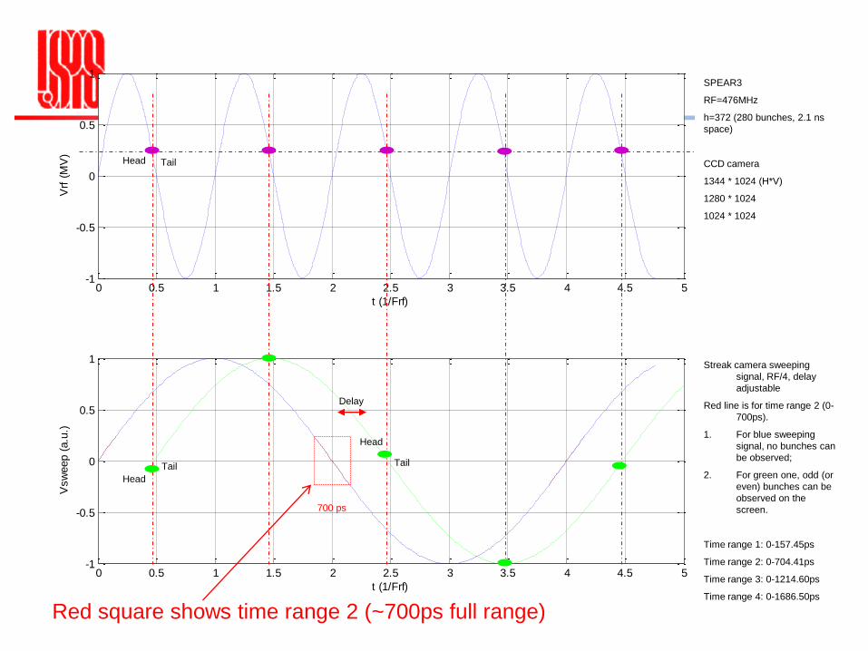
SPEAR3
RF=476MHz
h=372 (280 bunches, 2.1 ns
space)
CCD camera
1344 * 1024 (H*V)
1280 * 1024
1024 * 1024
Streak camera sweeping
signal, RF/4, delay
adjustable
Red line is for time range 2 (0-
700ps).
1. For blue sweeping
signal, no bunches can
be observed;
2. For green one, odd (or
even) bunches can be
observed on the
screen.
Time range 1: 0-157.45ps
Time range 2: 0-704.41ps
Time range 3: 0-1214.60ps
Time range 4: 0-1686.50ps
Head Tail
Delay
700 ps
Head
Tail
Head
Tail
Red square shows time range 2 (~700ps full range)
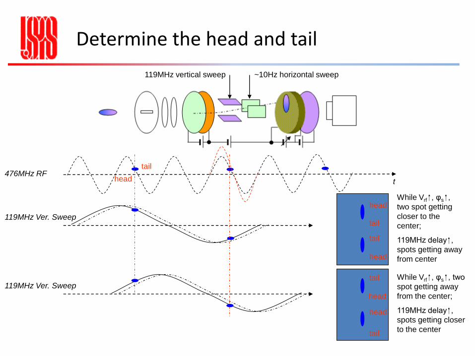
Determine the head and tail
119MHz vertical sweep ~10Hz horizontal sweep
t476MHz RF
119MHz Ver. Sweep
head
tail
head
head
tail
tail
While Vrf , φs ,
two spot getting
closer to the
center;
119MHz delay ,
spots getting away
from center
119MHz Ver. Sweep
head
tail
tail
head
While Vrf , φs , two
spot getting away
from the center;
119MHz delay ,
spots getting closer
to the center

Streak camera setup
slit
C5680-21S Main unit
M5675 Synchroscan sweep unit
M5679 Dual timebase extender unit
C4742-95-12ER digital camera
C4547 Streak trigger unit
ORCA-ER camera controller
Power supply unit
DG535 Digital delay/pulse generator
C5680/M5675/M5679 CCD
Camera controller
ORCA-ER
PC
Monitor out
Ext Trig
Camera head
Serial cable
Video cable
GPIB
Power
supply
DG535
C4547
frev
~ 10Hz
4
fRF
TrigInSyncIn
1/17/2010 5Streak Camera & Gated Camera Lab Primer
Hamamatsu C5680
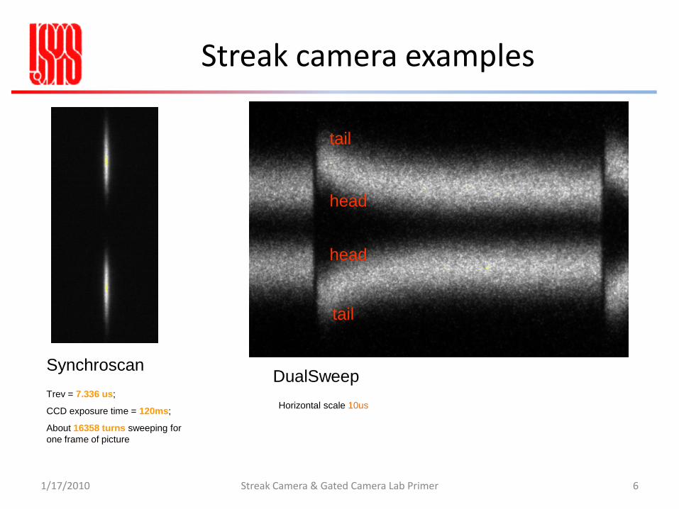
Streak camera examples
1/17/2010 Streak Camera & Gated Camera Lab Primer 6
Synchroscan
Trev = 7.336 us;
CCD exposure time = 120ms;
About 16358 turns sweeping for
one frame of picture
head
tail
head
tail
DualSweep
Horizontal scale 10us
Streak camera applications
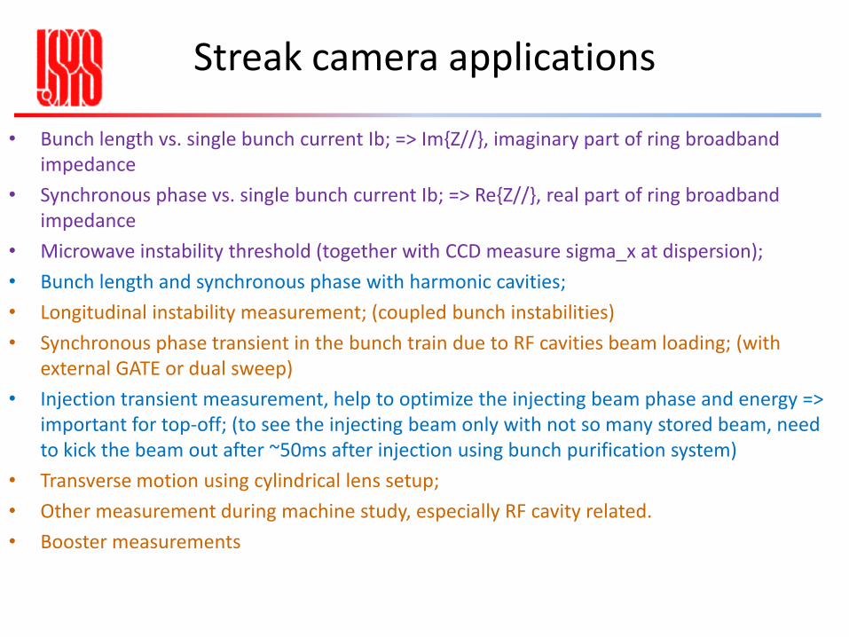
• Bunch length vs. single bunch current Ib; => Im{Z//}, imaginary part of ring broadband impedance
• Synchronous phase vs. single bunch current Ib; => Re{Z//}, real part of ring broadband impedance
• Microwave instability threshold (together with CCD measure sigma_x at dispersion);
• Bunch length and synchronous phase with harmonic cavities;
• Longitudinal instability measurement; (coupled bunch instabilities)
• Synchronous phase transient in the bunch train due to RF cavities beam loading; (with external GATE or dual sweep)
• Injection transient measurement, help to optimize the injecting beam phase and energy => important for top-off; (to see the injecting beam only with not so many stored beam, need to kick the beam out after ~50ms after injection using bunch purification system)
• Transverse motion using cylindrical lens setup;
• Other measurement during machine study, especially RF cavity related.
• Booster measurements
Streak camera Lab
• Don’t have the $200,000 camera here
• Hamamatsu HPDP-TA 8.1.0 software
• Stored streak camera images
• “Focus mode”, “Synchroscan mode”, “Dual sweep mode”
• Gaussian fit using Matlab
• Streak camera calibration using Etalon
• Resolution
• Bunch length vs. current => impedance
1/17/2010 Streak Camera & Gated Camera Lab Primer 8

Gated camera
1/17/2010 Streak Camera & Gated Camera Lab Primer 9
Roper/PiMax
~2ns gate minimum
Photo Cathode + accelerate mesh + MCP + phosphor
screen + CCD (1024*1024)
Gated Camera Timing
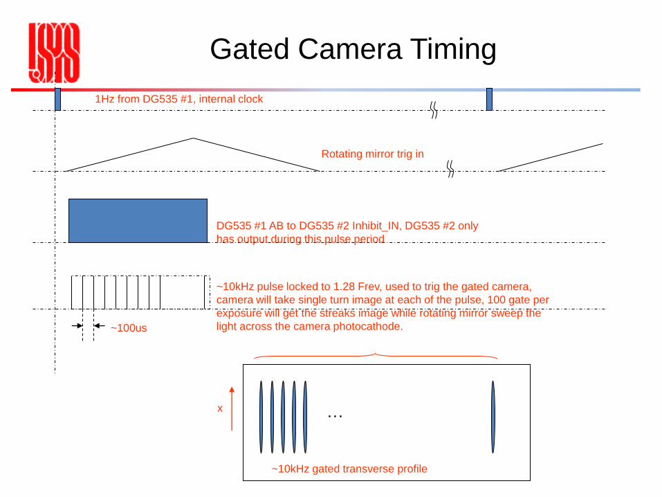
1Hz from DG535 #1, internal clock
Rotating mirror trig in
DG535 #1 AB to DG535 #2 Inhibit_IN, DG535 #2 only
has output during this pulse period
~10kHz pulse locked to 1.28 Frev, used to trig the gated camera,
camera will take single turn image at each of the pulse, 100 gate per
exposure will get the streaks image while rotating mirror sweep the
light across the camera photocathode.
…x
~10kHz gated transverse profile
~100us

Gated Camera Timing
1/17/2010 Streak Camera & Gated Camera Lab Primer 11
CH1 LED drive signal, 200kHz
repetition rate, 15ns minimum
CH2 Rotating mirror drive signal
from DS345, triangle
waveform/burst once/Phase 270
deg
CH3 Read back from the rotating
mirror controller, that's the real
rotating signal
CH4 Gate to PiMax camera
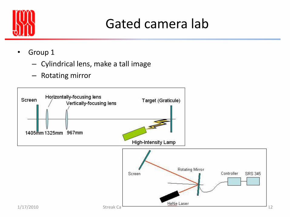
Gated camera lab
• Group 1
– Cylindrical lens, make a tall image
– Rotating mirror
1/17/2010 Streak Camera & Gated Camera Lab Primer 12
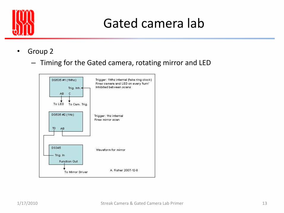
Gated camera lab
1/17/2010 Streak Camera & Gated Camera Lab Primer 13
• Group 2
– Timing for the Gated camera, rotating mirror and LED