Embed Size (px)
Citation preview

“StratoShield” Roof System Product Application Guide
Page 1 Revision No: 9.1 Date: November 16, 2009
INDEX 1.0 General ...............................................................................................................................4
1.1 Purpose of the Application Guide...................................................................................4 1.2 Product Contract Type ...................................................................................................5
A. “STRATOSHIELD” Standard Roof System ...............................................................5 B. “STRATOSHIELD” Component Roof ........................................................................5
1.3 Responsibilities of the Parties ........................................................................................6 A. "ACI Metal Roofing Systems" .................................................................................6 B. End Customer.............................................................................................................6 C. Owner.........................................................................................................................6
2.0 Product Description ..........................................................................................................7
2.1 General ..........................................................................................................................7 2.2 Physical Description .......................................................................................................7
A. General.......................................................................................................................7 B. Panel ..........................................................................................................................8 C. Seam ..........................................................................................................................9 D. Reinforced corrugations .............................................................................................9 E. Panel Flat .................................................................................................................10 F. Panel Clips ...............................................................................................................10 G. Panel Endlap ............................................................................................................12 H. Eave and Termination Perimeter Plates...................................................................13 I. Start of Panel Run.....................................................................................................13 J. Termination of Panel Run.........................................................................................14 K. Ridge Flashing..........................................................................................................14 L. Eave Trim and Gutter ...............................................................................................14 M. Fasteners .................................................................................................................14
2.3 Material and Finish ........................................................................................................15 A. Panel and Flashing Material .....................................................................................15 B. Sealants ...................................................................................................................15 C. Closures ...................................................................................................................15
3.0 Standard Roof System Application Guidelines and Use Limitations..........................16
3.1 General ........................................................................................................................16 3.2 Roof Configuration .......................................................................................................16
A. Rectangular ..............................................................................................................16 B. Beveled ....................................................................................................................16 C. Pitch Transitions .......................................................................................................16 D. Arched ......................................................................................................................17

“StratoShield” Roof System Product Application Guide
Page 2 Revision No: 9.1 Date: November 16, 2009
3.3 Roof Pitch.....................................................................................................................17 A. Minimum Pitch ..........................................................................................................17 B. Ponding ....................................................................................................................17 C. Deflection..................................................................................................................17 D. Maximum Pitch .........................................................................................................17 E. Standard Roof Pitch Limitations ...............................................................................18
3.4 Roof Drainage ..............................................................................................................18 A. Drainage Factors ......................................................................................................18 B. Roof Profile and Width..............................................................................................18 C. Eave Drainage Options ............................................................................................18 D. Effect of Pitch on Roof Drainage ..............................................................................19
3.5 Expansion and Contraction ..........................................................................................19 A. Temperature Differential ...........................................................................................19 B. Effect on Roof Panels...............................................................................................19 C. Standard Roof Size Limitations ................................................................................20 D. Provisions for Expansion /Contraction......................................................................20
1. Roof Fixity..........................................................................................................20 2. Roof Section Fixed at the Eave .........................................................................20 3. Rake ..................................................................................................................21 4. Penetrations.......................................................................................................21 5. Expansion Joints................................................................................................21 6. Inside Corners ...................................................................................................21
3.6 General Structural Considerations ...............................................................................22 A. Roof Dead Load .......................................................................................................22 B. Lateral Stability .........................................................................................................22 C. In-plane Deflection....................................................................................................22 D. Panel Clip and Clip Requirements............................................................................22
3.7 Insulation......................................................................................................................23 A. Insulation Provisions.................................................................................................23 B. Insulating Methods ...................................................................................................23
1. Condensation Control ........................................................................................23 2. Blanket Insulation...............................................................................................23 3. Spacer Blocks....................................................................................................24 4. Other Insulation Systems...................................................................................24 5. Insulation Facing................................................................................................24 6. Sub Framing ......................................................................................................25 7. Board Insulation.................................................................................................25
3.8 Roof Penetrations.........................................................................................................25 A. Critical Requirements ...............................................................................................25 B. Pipe Flashing............................................................................................................26 C. Curbs........................................................................................................................26 D. Clearances ...............................................................................................................27

“StratoShield” Roof System Product Application Guide
Page 3 Revision No: 9.1 Date: November 16, 2009
3.9 Corrosion......................................................................................................................27 3.10 Roof Appearance .......................................................................................................28 3.11 Erection ......................................................................................................................29
A. Erection Instructions .................................................................................................29 B. Erection Temperature...............................................................................................29 C. Erection Accuracy.....................................................................................................29
3.12 Roof Additions and Modifications ...............................................................................30
4.0 Load Span Tables and Section Properties ....................................................................30 4.1 “STRATOSHIELD” Panel Profile..................................................................................30 4.2 “STRATOSHIELD” Section Properties.........................................................................30 4.3 “STRATOSHIELD” Allowable Gravity Loads................................................................31
A. 24 Gauge Material ....................................................................................................31 B. 22 Gauge Material ....................................................................................................31
4.4 “STRATOSHIELD” Allowable Wind Uplift Loads..........................................................32 A. 24 Gauge Material with MPS 602 or MPS 603 Clip ..................................................32 B. 22 Gauge Material with MPS 602 or MPS 603 Clip ..................................................33 C. 24 Gauge Material with BA-602-8 or BA-603-8 Clip .................................................34 D. 24 Gauge Material with BA-602-12 or BA-603-12 Clip .............................................35 E. 24 Gauge Material with BA-602-16 or BA-603-16 Clip .............................................36

“StratoShield” Roof System Product Application Guide
Page 4 Revision No: 9.1 Date: November 16, 2009
1.0 General
1.1 Purpose of the Application Guide
This guide has been prepared to help the designer understand the “STRATOSHIELD” Roof System, its design and performance features. It is “ACI Metal Roofing Systems” intent that this guide, together with the specific roof application requirements, will allow the designer to determine how to best incorporate the “STRATOSHIELD” Roof System into a specific project. This guide will only describe the “STRATOSHIELD” system and does not make any recommendations for the application of the roof on any specific project. A professional designer should be employed to determine how best to integrate this roof system, with other roof and wall products and systems, to form a complete building project.
This Application Guide will provide the following:
Roof System Description Performance Capabilities Application Limitations Responsibilities for Proper Product Application and Use
The Product Application Guide is organized into the following sections:
Product Description - Describes the roof system, its materials, weather
resistance and structural performance characteristics. This description also includes confirming tests, design criteria and product warranties available from “ACI Metal Roofing Systems”.
Application Guidelines and Limitations
Architectural Details - These are the application details used by “ACI Metal
Roofing Systems” to detail a standard roof system. The details are suitable for reproduction.
1.2 Product Contract Type
We at “ACI Metal Roofing Systems” want to serve our customers to the best of our ability. We recognize that not all projects are the same nor require the same level of design from our personnel. Most projects will require the design and engineering to be done locally by the customer or their engineers. Other projects will require “ACI Metal Roofing Systems” to take responsibility to determine the best application of the roof system to our components.

“StratoShield” Roof System Product Application Guide
Page 5 Revision No: 9.1 Date: November 16, 2009
“ACI Metal Roofing Systems” will not take responsibility for the design or product application on projects for which we do not have complete information. To allow our customers to purchase our products in a way that offers them the best opportunity to enjoy a sound, well performing roof, we offer two ordering methods or contract types. Each contract type is tailored to place the design and product selection where it can best be accomplished.
A. “STRATOSHIELD” Standard Roof System
The Standard Roof System is designed by “ACI Metal Roofing Systems” and includes the roof materials required by the contract. The end customer will provide sufficient building information for “ACI Metal Roofing Systems” personnel to determine what materials will be required by contract. This system will include erection instructions, erection details, material and, when included in the purchase contract, material warranty.
Materials included in this roof system will be selected by “ACI Metal Roofing Systems” personnel and engineers to meet the requirements of the customer purchase contract. These materials include:
1. Roof panels 2. Clips 3. Perimeter attachment parts 4. Perimeters trim parts 5. Accessories 6. Related hardware, closures, and sealant
These materials will be selected in accordance with the standard “STRATOSHIELD” Application Guide and the “ACI Metal Roofing Systems” /Customer Contract.
B. “STRATOSHIELD” Component Roof
This type of roof order is a parts order for some or all of the parts and materials manufactured by “ACI Metal Roofing Systems” that are used in the “STRATOSHIELD” Roof System. The component roof order will not be reviewed by “ACI Metal Roofing Systems” personnel for completeness or compatibility of the parts ordered. “ACI Metal Roofing Systems” will process the order as a parts order and ship the parts without specific installation instructions or installation details.
The end customer will be responsible for all applications design, shop drawings, installation drawings and material take-off.
“StratoShield” Roof System Product Application Guide
Page 6 Revision No: 9.1 Date: November 16, 2009
No weather resistance warranty is available from “ACI Metal Roofing Systems” for a component roof. The roof designer or contractor must provide any weather resistance warranty.

“StratoShield” Roof System Product Application Guide
Page 7 Revision No: 9.1 Date: November 16, 2009
1.3 Responsibility of the Parties1.3 Responsibilities of the Parties
A. “ACI Metal Roofing Systems”
“ACI Metal Roofing Systems” will provide a roof system that will perform satisfactorily when used in accordance with this “STRATOSHIELD” Application Guide and Installation Instructions, as described in the purchase contract and disclaims all other responsibilities including warranties of fitness.
B. End Customer
The customer is responsible for ensuring:
a. That the “STRATOSHIELD” Roof System is suitable for the purpose for
which it is to be used and that the roof system meets all local, state, and/or federal building codes.
b. That the roof system is installed in accordance with good engineering and
construction practices and in accordance with the “STRATOSHIELD” Installation Instructions and shop drawings.
c. That the owner is advised of proper maintenance of the
“STRATOSHIELD” Roof System in accordance with good metal roof maintenance practices and the warranty terms.
C. Owner
The roof owner is responsible for protecting the roof from damage and performing regular maintenance such as removal of excess snow and ice, frequent clearing of drainage systems, and immediate repair of roof damage.
NOTE: Clarification or recommendations concerning “STRATOSHIELD” roof
applications, modifications, repairs, etc. must be directed to, and confirmed by, “ACI Metal Roofing Systems” project manager. Contact “ACI Metal Roofing Systems”
“ACI Metal Roofing Systems” 10009 Hwy 6 West Batesville, MS 38606 Phone 662-563-3613 Fax 662-563-0655

“StratoShield” Roof System Product Application Guide
Page 8 Revision No: 9.1 Date: November 16, 2009
2.0 Product Description
2.1 General
The “STRATOSHIELD” Roof System has been designed by “ACI Metal Roofing Systems” for use in architectural or functional applications where both appearance and weather resistance of the roof are primary concerns. Many standing seam roof systems have similar appearance but have major differences in their performance. The “STRATOSHIELD” Roof System has many advantages over most other roof systems and, when properly installed, will offer excellent weather resistance and be practically maintenance free.
The “STRATOSHIELD” Roof System is adaptable for use on new construction and as a replacement roof for existing buildings where weather resistance and thermal movement is the most important design consideration.
The following paragraphs provide a detailed description of the “STRATOSHIELD” Roof System, its materials, performance capabilities, confirming tests, design criteria, and the available warranties.
2.2 Physical Description
A. General
The “STRATOSHIELD” Roof System will consist of metal panels joined together by a patented factory-formed interlocking seam that is easily assembled and seamed in the field. The panel shape is identical for all three options. Only the seaming method is varied to achieve the various uplift performance levels. The lowest wind uplift level provides greater uplift loads than any of the existing non-seamed roof systems or “snap-together” seams on the market.
1. The ““RollLok”” seam does not require an electrical seamer to complete
the roof. All that is required to seam the “RollLok” seam is a hand seamer that is used to crimp the seam at clip locations only. The “RollLok” seam provides greater uplift loads than any of the existing no-seamed roof systems.
2. The “TripleLok” seam is formed using an electrically powered seamer that forms a seam that will resist higher uplift loads than any seamed roof system on the market.
3. The “QuadLok” seam is used in very high wind load portions of roofs where other roof systems will require narrower 2'-6" purlin spacing, narrower 18" wide panels, thicker 22 gauge panels or a combination of all these options the “QuadLok” seam will allow a 24 gauge panel over 5'-

“StratoShield” Roof System Product Application Guide
Page 9 Revision No: 9.1 Date: November 16, 2009
0" purlin spacing to out perform most 22 gauge panels over 4'-0" purlin spacing. The “QuadLok” seam is formed by seaming over the “TripleLok” seam to further tighten and form an additional strengthening bend in the seam. The “QuadLok “ seam is typically used in areas of the roof that require extreme uplift resistance such as the corner and edge zones of roofs in high wind areas.
B. Panel
The panel will be fabricated from steel, which is coated with Galvalume, and optional factory applied paint. Galvalume coated steel sheet will provide a long- lasting weathering membrane. Galvalume coating has a proven weather resistance in excess of 20 years. The steel sheet is impervious to moisture and will resist falling objects and roof traffic better than other known roof membranes commonly used. The steel panels will be formed into a shape that will resist live load and wind uplift without the complexity and cost of additional sub-framing as required on most other roofing systems. The ultimate performance of a Galvalume coated steel panel is determined by effectiveness of the design of the steel panel, perimeter seals, and panel attachment methods.
1. The “STRATOSHIELD” Panel will be a factory precision roll-formed pan panel with side seams formed by 14 forming stations. The panel will have a nominal 3” high rib/seam and be a nominal 24” wide. Panels will have a male and female vertical leg formed so the two legs can be seamed in the field with a hand seamer or motorized field seaming machine, depending on the final desired seam.
2. Maximum panel lengths will be provided to minimize the need for end
splices. Maximum length will be controlled by transportation considerations (usually 50').
3. Panel lengths are cut using a one-piece die that sheers the panel to
length, makes factory notches in the male and female sides and punches end lap holes in the panel flat. By using a single die to sheer, notch and punch, indexing of the panel ends and the notches are precisely controlled. The panel line is capable of producing panels with length tolerances within "1/16" from panel to panel.
4. Weight of panels is shown in the table below:
Panel
Width
24 ga. (lbs/sf)
22 ga. (lbs/sf)

“StratoShield” Roof System Product Application Guide
Page 10 Revision No: 9.1 Date: November 16, 2009
“STRATOSHIELD”
24"
1.168
1.441
C. Seam
The panel seam is designed to perform three functions that are critical to the performance of the roof system. These functions are:
1. Seal the sides of the panels without through fasteners to minimize water
penetration.
2. Provide attachment location for structural clips.
3. Structurally connect the sides of the panels to form a continuous weather tight membrane and resist bending loads.
Water resistance of the seam is developed by factory-applied sealant. The factory-applied sealant is injected into the female side of the seam during panel forming. There are three seams available for the same “STRATOSHIELD” profile panel. Each of the three seams provides a different level of wind uplift resistance. “STRATOSHIELD” panel sidelap is formed using one or a combination of seaming methods: Hand seaming the panels only at clip locations tightly clamps the panel seam to the clip and structural system to provide a water resistant seam that will resist the uplift forces in the main field of a roof for most design load conditions and forms the “RollLok” seam. Continuously field seaming the adjacent panel sides over each other to interlock the two panels, forms the “TripleLok” seam. The interlocked panels form a watertight seal that will resist separation even if the panels are severely lifted during design storm conditions. The “TripleLok” seam is partially formed in the factory and completed in the field with a powered seamer.
“QuadLok” seaming is used primarily at roof corners and sometimes in the perimeter zone where the roof is exposed to severe wind uplift in high wind areas. The “QuadLok” will reinforce the panel “TripleLok” seam so the panel
“StratoShield” Roof System Product Application Guide
Page 11 Revision No: 9.1 Date: November 16, 2009
placed over 5' purlin spacing will perform better than other systems placed over 3'6" purlin spacing.
D. Reinforced Corrugations
The corrugations have a stiffening rib formed into the lower base of the corrugation. This stiffener rib strengthens the steel membrane so it will enhance the resistance to roof loads such as erection loads, live loads and wind uplift. The panel corrugations will also provide a raised platform for the panel seam three inches (3") above the panel surface. By raising the seam above the panel flat, roof water drainage will seldom flow above the seam.

“StratoShield” Roof System Product Application Guide
Page 12 Revision No: 9.1 Date: November 16, 2009
E. Panel Flat
The flat area between corrugations will have shallow corrugations formed to minimize the effect of oil-caning in the panel sheet or striations. The striations consist of a series of slight offsets (less than a material thickness in depth) formed in the panel flat. The effect of the striations is to break up any oil-canning in the flat to relative narrow portions of the panel. The visual effect of the striations are pleasant and they fade from view when the panel is viewed from a distance, leaving the appearance that the panel has a flat smooth surface. Experience has shown that the striations reduce the appearance of oil canning better than minor ribs or pencil ribs.
F. Panel Clips
Panel clips fasten the roof panels to the structure. There are two types of panel clips: Fixed Clips and Floating Clips. 1. Fixed clips are fabricated in one piece from .031" thick galvanized steel. Fixed clips do not provide for independent expansion and contraction of the roof panels and the building structural system. Fasteners to attach the fixed clips to 16 gauge secondary structural members are a minimum of two 1/4"-14 self drilling screws.
Fixed clips are available in three heights: Zero clearance, Low and High. The Low clip will raise the panel flat approximately ½" above the structural system to provide clearance for up to 4" of blanket insulation. The High clip will hold the panel flat approximately 1-1/2" above the structural system to provide for up to 10" of blanket insulation and foam blocks as required.
The bases of the fixed clip are designed with feet to will bear directly on the purlin and project through the insulation to minimize the rocking of the clip over insulation that will occur with other clips.
2. The floating clips are available in two types - Standard Movable clips and
Factory Mutual approved Movable Purlin Stabilizing clips. The standard movable clip has a smaller 2-hole slide base and the Movable Purlin Stabilizing clips have a longer 4-hole base.
a. Standard Movable clips are designed to allow the panel to float over the
secondary structural system. These clips will have a tab and a base with sliding interlock allowing the roof 1-1/2" of expansion and 1-1/2" of contraction movement. The floating clip tab will move in the sliding interlock of the Galvanized steel clip base. The clip base will be protected

“StratoShield” Roof System Product Application Guide
Page 13 Revision No: 9.1 Date: November 16, 2009
from corrosion by galvanized coating that has similar weather resistance to that of the panel coating.
The tab portion of the clip will have a factory-applied sealant. This factory- applied sealant will merge with the factory sealant installed in the female leg of the panel. The merged sealant in the seam will form a water-resistant seal between the sidelap.
The clips will be attached to 16 gauge, cold-formed, secondary structural
members with two #14 x 1-1/4" self-drilling screws. Fasteners required for other types of secondary structural members will be determined by building applications or the substrate used on the building.
Standard Movable clips are offered in two heights: low, and high. The movable tab of the floating clip is locked in the center of its slide range by centering tang. When the structural screws are installed, the base is compressed and releases the patented centering device.
The base of the panel clips has domed protrusions that will bear directly on the purlin structure and lock the clip base tightly to the purlin. Other clip bases have to compress the blanket insulation between the bottom of the clip base and the purlin. The large flat surface area of the clip base of other clips prevents a solid bearing on the structural member resulting in clip rotation after installation.
b. Movable Purlin Stabilizing clips have been developed and tested to
provide improved purlin lateral stability when tested, using the (AISI-TS-8-02) “Base Test” method of testing purlin lateral bracing. These clips minimize the tendency of the purlin lateral to roll without restricting the ability of the panel to expand and contract over the purlin. These clips are designated MPS clips. With the purlins tested, the MPS clip will provide approximately 80% of the purlin lateral bracing that would be provided by the installation of an “R” panel.
MPS clips are designed to allow the panel to float over the secondary struc-
tural system. These clips will have a tab and a longer base with sliding interlock allowing the roof 1-3/4" of expansion and 1-3/4" of contraction movement. The floating clip tab will move in the sliding interlock of the galvanized steel clip base. The clip base will be protected from corrosion by galvanized coating that has similar weather resistance to that of the panel coating.
The tab portion of the clip will have a factory-applied sealant. This factory-
applied sealant will merge with the factory sealant installed in the female leg
“StratoShield” Roof System Product Application Guide
Page 14 Revision No: 9.1 Date: November 16, 2009
of the panel. The merged sealant in the seam will form a water-resistant
seal between the sidelap.
Panel clips will be attached to 16 gauge, cold-formed, secondary structural members with a minimum of two #14 x 1-1/4" self-drilling screws. The longer base has space for more fasteners with four holes in lieu of two. Fasteners required for other types of secondary structural members will be determined by building applications or the substrate used on the building.
MPS clips will be offered in two heights: low and high. The movable tab of the floating clip is locked in the center of its slide range by centering tang that is released when the clip fastener is installed. The base of the panel clips has domed protrusions that will bear directly on the purlin structure and lock the clip base tightly to the purlin.
G. Panel Endlap
Panel endlaps will be required if the panel run length is greater than the maximum length panel that can be shipped. Panel endlaps provide a continuation of the panel sidelap seal along the end of the panels where the two panels join end to end. Because the “STRATOSHIELD” Roof System is designed to be water resistant on low slope roof applications, the endlap seal is of a gasket design. The gasket design will resist moisture entry from water flowing over the endlap from either direction. This type of design is necessary because on low slope roofs, wind can force water up the slope and ice damming can cause water to temporarily pond along the panel flat. To achieve a gasket seal, the two light gauge roof panels have butyl tape sealant placed between them and are then tightly clamped between two relatively heavy gauge rigid plates. The two rigid plates will distribute the fastener clamping force along the light gauge panel material resulting in a uniform compression of the butyl sealant placed between the panels. The rigid plates will also extrude the sealant into the fastener hole around the fastener shank and under the fastener sealing washer to seal the panels and fastener holes from moisture entry.
The panel endlap splice will not be attached to the secondary structural so any roof movement due to differential expansion and contraction between the roof panels and the roof structurals will not be restricted.
The panel endlaps will be located along a straight line (not staggered) and at a fixed distance from the nearest purlin or joist down slope from the panel end.
“StratoShield” Roof System Product Application Guide
Page 15 Revision No: 9.1 Date: November 16, 2009
The “STRATOSHIELD” endlap is unique and superior to others because:
1. The back-up plate is stamped to conform to the panel corrugation. A back-up
plate that conforms to the panel corrugation will assist on locking the panel endlap on module. The endlap can be placed as close as 2" or as far as 4” beyond the upslope edge of the secondary structural member.
2. The panel seam members are factory-notched for the endlap condition to
prevent build up of materials that occur at a four way corner. Factory-notching the panels prevents field notching errors at this critical portion of the roof thereby improving the assurance of a weather resistant endlap.
3. The cinch strap is fabricated from stainless steel having weather resistance
very similar to the coating used on the roof panel. This assures a long life and low maintenance roof system. The cinch strap provides clamping force to the panel material thereby increasing the bearing resistance against the lap fasteners.
H. Eave and Termination Perimeter Plates
1. Eave perimeter plates are installed over the eave member so the outer edge
extends over the wall panel. The eave perimeter plate will provide a solid, non-compressible attachment point for the eave end of the panel run. The eave end of the panel run must resist the forces of the panel movement during differential expansion and contraction between the roof panel and the roof structurals. If the panels were not tightly clamped to the eave perimeter plate, all the forces of expansion and contraction would be applied to the fastener shaft and the fastener hole resulting in elongating of the fastener holes and eventual entry of moisture. The eave perimeter plate also provides a means of locating the eave fastener outside the building envelope so any moisture entry around eave fasteners will have a minor effect on the building contents.
2. The termination perimeter plate is installed along the rake angle. The
termination perimeter plate will provide a shelf to attach the panel flat of the last panel along the termination rake. The termination perimeter plate has slotted holes in the base for attachment to the rake angle with shoulder fasteners. The use of shoulder fasteners in the slotted holes will provide a means for the roof to move independent of the roof structurals during expansion and contraction of the roof panels.
I. Start of Panel Run

“StratoShield” Roof System Product Application Guide
Page 16 Revision No: 9.1 Date: November 16, 2009
1. The start of a panel run requires a full width panel and is accomplished by
installing panel clips along the rake angle. The female leg of the panel is attached to the tab of the start clip when the rake trim is fastened to the roof panel. The advantages of using a panel clip for the starting of a panel run is that the clip may be attached to the rake angle before the insulation is placed and its exact location can be marked on the rake angle leg. With the clip in place before the insulation is started, start positioning of the roof panel is a simple matter of establishing the correct eave overhang and placing the female leg over the clip tab.
2. If it is desirable to reposition the location of the roof panel sidelaps, the panel
run may be started with a partial panel. To start the roof with a partial panel, a termination perimeter plate is used along the rake instead of panel clips. The partial panel flat is attached to the termination perimeter plate in the same manner as the termination panel is attached at the end of a panel run.
J. Termination of Panel Run
1. The termination of the last panel run at the rake is accomplished in the panel
flat. By terminating the panel run in the flat, it is not as critical to hold the panel on module as with other systems that terminate on the panel corrugation. Panel module does affect the fit up of the closures and the ability to properly seam the panel. This method of termination also accommodates greater variance on the square of the roof structure.
K. Ridge Flashing
1. The design of the ridge flashing accommodates roof expansion and
contraction. The ridge flashing will have a finish that matches the roof panel finish.
L. Eave Trim and Gutter
1. The roof panel is sealed to the wall panel with an eave flashing. The eave
flashing provides a gasket sealing point to seal the underside of the roof panel and acts as a shingle to shed water over the outside of the wall panel. The eave trim is standard with or without gutter.
2. The eave trim is available in two types. One type consists of a one piece trim
section to be used if the wall panel is installed before the roof panel. The other type is a two piece trim to be used if the roof panel is installed before the wall panel.
M. Fasteners

“StratoShield” Roof System Product Application Guide
Page 17 Revision No: 9.1 Date: November 16, 2009
1. The “STRATOSHIELD” Roof System will not have exposed through fasteners that penetrate the roof membrane over the building envelope except at panel endlaps on roof runs that are longer than the length a panel can be shipped.
A. Endlap fasteners
a. Only four (4) endlap fasteners will be required to seal the panel endlaps.
b. Endlap fasteners will be oversized #17 fasteners to minimize potential for fastener strip out.
B. All exposed fasteners will be self-drilling or self-tapping and not require
special tools other than industry standard screw guns. Fasteners will have metal backed neoprene sealing washers.
2.3 Material and Finish
A. Panel and Flashing Material
1. The roof panels will be of 24 ga. or 22 ga.1 steel, 50,000 psi minimum
yield strength (ASTM A792, Grade 50), coated with AZ50 (minimum) aluminum/zinc alloy for painted finish or AZ55 aluminum/zinc alloy for unpainted finish.2
2. The flashing and trim will be 26 ga. steel 50,000 psi minimum yield
strength (ASTM A792 Grade 50), coated with AZ50 (minimum) aluminum/zinc alloy.
B. Sealants
1. The seam sealant will be a non-drying, non-hardening, non-oxidizing butyl
rubber based sealant specifically formulated for factory sealing standing seam roof panels.
2. Sealant for the eave, end splice, ridge flashing, and rake trim will be non-
drying, non-hardening, butyl based tape sealant specifically formulated for field application at temperatures of 20 F to 120 F.
3. Service temperature of both sealants will be -60 Deg. F to 180 Deg. F.
C. Closures
1 22 ga. available on special request with extended delivery time required. 2 Other materials and finishes available on special request with extended delivery time required.

“StratoShield” Roof System Product Application Guide
Page 18 Revision No: 9.1 Date: November 16, 2009
1. The end dam to be used at the ridge and high side of a single slope roof is a die-formed steel closure with factory punched holes. The end dam seals the outside of the panel at the ridge or high edge of a single slope roof panel to the ridge or high edge of roof flashing. This seal is developed using gasket techniques similar to those used at the endlap. The tape sealant is sandwiched between the roof panel, which is fully supported by a rigid heavy gauge back-up channel and the flange of the end dam. The fasteners placed in the factory-punched holes clamp the back-up channel and end dam together. The clamping force uniformly compresses the sealant between the panel and the end dam causing the sealant to be extruded with over one ton of force. The extruded sealant provides a seal that will resist wind-blown water.
3.0 Standard Roof System Application Guidelines and Use Limitations
3.1 General
The “STRATOSHIELD” Roof System is a heavy-duty structural or functional roof system intended for use where water resistance, expansion/contraction and insulation efficiency are of prime importance.
“ACI Metal Roofing Systems” has designed the “STRATOSHIELD” Roof System to be water resistant and have a long life expectancy when properly specified by a qualified building designer who is aware of the conditions normal to industrial and commercial roof installations. The building designer should analyze the requirements of the specific building being covered with the “STRATOSHIELD” Roof System to determine if the features and limitations of the system will be compatible with the design requirements of the specific building.
3.2 Roof Configuration
A. Rectangular
The “STRATOSHIELD” Roof System is designed primarily for industrial/commercial roofs with single or double sloped rectangular areas. “STRATOSHIELD” roofs can be applied to more complex configurations, but consideration must be given to the potential for increased material and labor cost and potential erection and weather tightness problems resulting from the complexity of the parts and their installation. More complex roof configurations, such as those listed below, must be specifically approved by “ACI Metal Roofing Systems” in writing to be covered by any “ACI Metal Roofing Systems” guarantee.
“StratoShield” Roof System Product Application Guide
Page 19 Revision No: 9.1 Date: November 16, 2009
B. Beveled
Non-rectangular configurations such as beveled eaves, beveled gables, hips and valleys, are designed similar to their rectangular counterparts with the exception of the transitions which require field cutting of the panel and special factory or field-fabricated flashing parts.
C. Pitch Transitions
Changes in roof pitch will require a transition joint or ridge between the different pitched roof sections. The transition joint may require provisions for expansion and contraction of one or both roof planes. The designer may be required to provide special secondary structurals to accommodate fixing the roof panels at locations other than the eave. Over the eave transitions are discouraged due to the inability to ensure weather tightness.
D. Arched
Arched roofs are usually on structures with roofs set to a curved plane either laterally or longitudinally. The “STRATOSHIELD” Roof System is not recommended for use on arched roofs without review by “ACI Metal Roofing Systems”.
3.3 Roof Pitch
A. Minimum Pitch
Minimum allowable roof pitch is primarily determined by the anticipated amount of water ponding expected on the roof. Building width, roof deflection, parapets, gutter design, rainfall intensity, wind direction and snow and ice damming (geographical location) are the common factors determining water ponding.
Low pitch roofs (below 2:12) in heavy snow and ice regions should not be designed with conditions that will accumulate snow or ice such as high parapets and wall above the roof transitions.
Long roof runs (in excess of 200') in heavy rain areas such as the Gulf Coast should have a roof pitch greater than 1/4:12 to minimize water build up due to heavy wind and rainfall.
B. Ponding

“StratoShield” Roof System Product Application Guide
Page 20 Revision No: 9.1 Date: November 16, 2009
The “STRATOSHIELD” Roof System utilizes gasket type joints to resist standing water on low pitch applications. These joints are designed to resist momentary flooding, such as that caused by heavy rain with wind gusts. Permanent water damming such as caused by obstructions, clogged valley gutters or long-term ice damming must be avoided.
C. Deflection
Lower roof slopes (less then 1:12) tend to increase the amount of ponding and consequently increases the deflection of supporting structurals which may, in turn, cause additional ponding.
Concentrated loads and other loads such as suspended ceilings, lighting, HVAC equipment, sprinklers, and cranes that are supported by the same structurals that support the roof panel may cause excessive roof deflection with resulting ponding.
D. Maximum Pitch
Maximum roof pitch is primarily determined by the effect upon the supporting structure, erection requirements and trim/flash/gutter designs. High pitch roofs, especially those used with sloped metal re-roof framing systems, when subjected to gravity roof loads, may develop substantial "in plane" loads and may require special bracing and may require special roof panel attachment.
E. Standard Roof Pitch Limitations
The “STRATOSHIELD” Roof System=s minimum allowable roof slope is 1/2:12 as standard. A 1/4:12 sloped roof must be approved by “ACI Metal Roofing Systems”.
The “STRATOSHIELD” Roof System=s maximum allowable roof slope is 6:12 as standard. Greater slope requires approval from “ACI Metal Roofing Systems”.
The standard pitch limitations are based on general and typical roof applications. It is the customer’s responsibility to assure that the specified roof slope is adequate for the building and environmental conditions of the specific project.
3.4 Roof Drainage
A. Drainage Factors
Roof drainage is an important factor in the design of a building. It is affected by building conditions such as slope, size, deflections and evenness of the roof. It is

“StratoShield” Roof System Product Application Guide
Page 21 Revision No: 9.1 Date: November 16, 2009
also affected by environmental conditions such as rainfall intensity, snow and ice occurrence and wind factors.
B. Roof Profile and Width
The roof drainage design criteria will limit the width of the building by the systems ability to carry off rain water. On a single slope roof, the high eave is more suitable for parapet or facade treatment and the entire roof area drains to the low eave. The absence of a ridge and gutter and downspout system at one eave provides material and erection savings. On a gabled roof, the ridge divides the roof area so each eave handles half the roof drainage. With a gutter and downspout system at each eave, a wider roof area can be drained. For extremely wide roof areas, multi-gabled roofs will be required. The roof is divided by alternate ridges and valleys with drainage at each eave and at the valleys. The valleys require an interior drain pipe system.
C. Eave Drainage Options
Eave drainage is usually by exterior mounted gutter and downspouts. Where suitable for appearance and ground run-off conditions, gutters are not provided and the run-off occurs at the roof edge.
Interior eave gutters are required when the low eave is at a parapet or wall, or when icing is so severe that the gutter and drainpipes must be heated by the building's interior.
In severe snow and ice regions, the eave gutters may be omitted and the roof edge extended so run-off and icing occurs away from the wall surface.
D. Effect of Pitch on Roof Drainage
Steep roof slopes increase the rate of run off of short duration, high intensity rainfalls. In regions where snowfall is a factor, snow slides down steep roofs could overflow and dam the gutters and downspouts.
3.5 Expansion and Contraction
A. Temperature Differential
Theoretically, the temperature differential between the roof's surface and the supporting structural determines the amount of differential expansion/contraction

“StratoShield” Roof System Product Application Guide
Page 22 Revision No: 9.1 Date: November 16, 2009
movement the roof system must accommodate. In actual use, the flexing of the supporting structure and minor oil-canning or strain in the roof absorbs some of this movement. Insulated structures experience greater temperature differentials than un-insulated structures.
In setting differential temperature requirements, consideration must be given to panel color, building location, infrared heating by the sun, the cooling effect of structures, insulated buildings that are temperature sensitive, or in extreme climates, may require wider than normal temperature ranges. Differential temperatures of insulated buildings with dark roofs in mountain areas are particularly high.
Differential temperature movement may be estimated using rational analysis. When an unrestrained steel panel 100' long is subjected to a 100E F temperature change, its length changes 0.78". Temperature movement may be restricted by panel restraint, but doing this is impractical because of the large forces required. A 24 gauge “STRATOSHIELD” panel would require about 10,000 pounds force to restrain it. Many specifications require 100E F temperature change for differential movement between the panel and its support structure. Conditions that require differential expansion and contraction temperatures in excess of 100E F require special approval from “ACI Metal Roofing Systems” to qualify for any guarantee.
B. Effect on Roof Panels
In the direction parallel to the eaves, “STRATOSHIELD” roofs absorb the differential movements by flexing of the panel profile and sidelaps. Since the panels are only 24" wide, the differential movement at each panel is insignificant and does not accumulate in the direction parallel to the panel corrugation. In panel runs less than 50', the differential movement is absorbed by flexing of the support structure and minor oil-canning or strain in the roof panels. In roofs with panel runs that are in excess of:
1) 50' when the secondary structurals are light gauge zee or cee members, 2) 30' when the roof is erected on more rigid structurals such as heavy zee or
cee purlins, or purlins that are supported by stiff attachments, bar joists, or hot rolled beams,
The “STRATOSHIELD” roof must be erected to absorb the differential movement between the panel and its support by sliding of the 2 piece floating clips and specially designed perimeter flashing.
C. Standard Roof Size Limitations
1. The following size limitations apply to each separate roof section. A roof section is defined as an "in plane" section separated from other sections by perimeter transitions such as eave, gable, ridge, parapet and expansion

“StratoShield” Roof System Product Application Guide
Page 23 Revision No: 9.1 Date: November 16, 2009
joints. These size limitations are based on a 100 F maximum temperature differential between the roof surface and the supporting structure.
2. Roof section length (dimension parallel to building eave) is not limited.
3. Maximum standard roof section width (dimension parallel to panel sidelap or
building rake) is limited as follows:
225' - with floating clips.
Greater roof section widths require approval from “ACI Metal Roofing Systems”.
D. Provisions for Expansion /Contraction
1. Roof Fixity
Any given section of roof with floating clips, must be rigidly attached by only one line of fasteners running along the eave or in special designs running along the ridge of the building.
2. Roof Section Fixed at the Eave
As standard, when using the floating clip, the “STRATOSHIELD” Roofs are rigidly attached to the supporting structure only at the low eave. At the high eave, ridge, rake and transitions, the edge of the roof is closed with flashing designed to absorb the differential movement between the roof and the adjacent structures.
3. Rake Along rakes, the edge of the roof is attached to the supporting structure and
closed to the adjacent structure with clips and flashing designed to allow free roof movement in the direction parallel to the rake. The rake flashing must be secured to the walls or adjacent structurals with counter flashing or reglets which are designed to allow free movement of the flashing.
4. Penetrations
See penetrations in section 3.8 for accommodating panel movement.
5. Expansion Joints

“StratoShield” Roof System Product Application Guide
Page 24 Revision No: 9.1 Date: November 16, 2009
Expansion joints ties separate roof sections together yet allow each section to expand and contract independently. Expansion joints are required on extra wide buildings, at structural expansion joints, at the transition of different roof pitches, at maximum panel runs and at the transition of different roof types.
For expansion joints running parallel to the eave, the “STRATOSHIELD” Roof System utilizes a vertical step between the two roof sections. The step allows the lower roof to be closed with a flashing that absorbs the differential movement. The upper roof is rigidly attached similar to a low eave condition.
For expansion joints running parallel to the end wall, the “STRATOSHIELD” Roof System utilizes a small vertically raised parapet between the two roof sections.
6. Inside Corners
Where an inside corner caused by a change in the width of the roof creates a condition where adjacent panels have different fixed points, the accumulated expansion/contraction movement of the roof is different along the adjacent panels on either side of the inside corner. When the distance between the panel attachment point at the low eaves is 30' or less, the roof system will absorb the differential movement. When the distance between the attachment point at the low eaves exceed 30', an expansion joint is required between the adjacent panel sidelap to accommodate the differential movement.
Where an inside corner is located at the high eave of a roof fixed at the low eave, the accumulated expansion/contraction movement is the same on the adjacent panels on either side of the inside corner, thus there is no differential movement.
3.6 General Structural Considerations
A. Roof Dead Load
The structure support the roof system should include the dead weight of the panel system in the design calculations. The weight of the panels is given in the section titled product description.
B. Lateral Stability
“StratoShield” Roof System Product Application Guide
Page 25 Revision No: 9.1 Date: November 16, 2009
Because the roof panels are attached to the supporting structurals with sliding clips, the roof panels do not provide lateral bracing to the secondary structurals. Bridging or brace angles may be required to stabilize the roof secondary structurals.
C. In-plane Deflection
Because the roof system is rigidly attached only to one structural member per roof section, usually the eave member, that member must have sufficient strength and stiffness or be braced to resist any in-plane (outward) deflection caused by the roof load. As the roof pitch increases, other factors being equal, the in-plane load increases.
D. Panel Clip and Clip Requirements
1. One panel clip is placed at the intersection of each roof panel sidelap and roof
structural, except where the panel is attached to the underlying structure with through fasteners.
2. The clips hold the roof panel 1/2", or 1-1/2" above the structural. The clips
providing a stand-off are designed to provide a space for the roof insulation between the panels and structurals.
3. The floating clip has a sliding interlock to allow for 1-3/4" expansion and 1-
3/4" contraction movement of the roof panel as a standard. Longer slide clips are available.
When centered during installation, the floating clip will accommodate a roof panel movement of " 1-3/4". This is equal to the thermal movement in a 225' panel run when subjected to a temperature differential of 100˚ F between the roof panel and its support structure. The standard sliding clip base provides a 1" x 2" bearing surface with two 3/8" diameter holes for attachment of the clips to the supporting structure. The surfaces to which the clips are attached must not deviate more than "1/4" from their common plane and must have sufficient strength and stiffness to resist the load imposed by the base of the clip and its attachment fastener.
The clip attachment fasteners will be provided by “ACI Metal Roofing Systems” as appropriate for the specified roof design requirements and the specified structural member material, size and spacing.
a. The panel clip tab will be of 0.031" steel, 50,000 psi minimum yield strength with G90 galvanizing.
“StratoShield” Roof System Product Application Guide
Page 26 Revision No: 9.1 Date: November 16, 2009
b. The clip base will be of 0.064” steel, 50,000 psi minimum yield strength with G90 galvanizing.
3.7 Insulation
A. Insulation Provisions
The “STRATOSHIELD” Roof provides a space for insulation between the roof and the supporting structurals. This is accomplished by a perimeter plate, which supports the roof in a plane slightly above the top of the structurals. The perimeter plate and clips are designed to provide a positive mechanical tie between the roof and the supporting structure with minimum interruption of the insulation.
As standard, the roof clips and eave plate are designed to provide either a nominal 1/2" or 1-1/2" insulation space between the roof and supporting structurals. Insulation space greater than 1-1/2" will require special order and approval by “ACI Metal Roofing Systems”.
B. Insulating Methods
1. Condensation Control With any insulation system, the proper design and installation of vapor retarder and ventilation systems are of the utmost importance to prevent condensation and the resulting problems of moisture damage, dripping and loss of insulation efficiency. “ACI Metal Roofing Systems” recommends the services of a qualified engineer to specify the appropriate vapor control system for the specific building and environmental conditions.
2. Blanket Insulation
Blanket insulation and clip height selection are interdependent design considerations. Blanket insulation up to 4" thick can be used with the low clips having a nominal 1/2" stand-off. For thicker insulation up to 6", the high clip and a foam spacer block are required. Insulation thicker than 6" can be used provided the insulation gives support for the panel flat when fully compressed, but does not force the panel flat to be bowed above its normal horizontal plane. Generally, each 1" thickness of fiberglass insulation will compress to about 1/8" over a 3" wide purlin. For example, a 3" thick insulation compresses to about 1/2". A 1/2" space between the purlin and panel will accommodate 3" to 4" of insulation (the clip will be raised slightly as it is sitting on compressed insulation), or a 1-1 /2" space will accommodate 6"

“StratoShield” Roof System Product Application Guide
Page 27 Revision No: 9.1 Date: November 16, 2009
of compressed insulation plus a insulation block for increased efficiency (reduced heat flow).
The insulation is stretched across the supporting structurals with the “STRATOSHIELD” roofs applied directly over the insulation. Between the structurals, the insulation assumes its full thickness. Over the structural, the insulation may assume the thickness of the space between the structural and the roof. This provides much greater insulation efficiency than the common systems which completely compress the insulation between the roof and the structural.
3. Spacer Blocks
Optional spacer blocks may be provided with the roof panels as installation aids when installing the roof with 1-1/2" stand-off clips only. DO NOT USE THE 1/2" STANDOFF CLIP WITH SPACER BLOCKS.
4. Other Insulation Systems
There are several insulation systems, which provide a clip or bracket to support thicker insulation between the structurals. A blanket or board insulation is then placed over the joists to insulate the space between roof and structurals. These systems may work well with the “STRATOSHIELD” Roof; however, they may affect the appearance or structural performance of the “STRATOSHIELD” Panel System and may void standard warranties. To obtain approval of these systems and maintain a guarantee, check with “ACI Metal Roofing Systems”. Additional details are available from the insulation system suppliers.
5. Insulation Facing
Condensation occurs when warm, moist air comes into contact with a cold surface, i.e., a cold panel surface on or below the dew point.
In most sections of the United States, keeping warm, moist air away from the panel can prevent condensation on the underside of a metal roof. With metal roofs, this is often accomplished by placing blanket insulation and a vapor retarder immediately below the panel. The vapor retarder should be on the warm side of the insulation. For the blanket insulation to work, the insulation must keep the vapor retarder's surface above its dew point and the vapor retarder must prevent water vapor from reaching the cold surface of the underside of the panel. In addition, it must prevent streams of warm air from passing over the surface of the cold panel. In order to achieve this, the perm rating of the vapor retarder must be very low because the perm rating of the

“StratoShield” Roof System Product Application Guide
Page 28 Revision No: 9.1 Date: November 16, 2009
metal roof is substantially 0.0 (zero). Metal roofs are less forgiving than some other types of roofing such as wood shingles that breathe. The body of the vapor retarder must not have pin holes or other tears and the edges of the vapor retarder must be joined in such a way they prevent both water vapor and air penetration. A vapor retarder having a perm rating of 0.02 is recommended and “ACI Metal Roofing Systems” warranty requires a maximum of 0.05. For further information on condensation control in metal buildings, refer to the MBMA Condensation Fact Sheet.
6. Sub Framing
On roofs where there is insufficient space for the desired thickness of insulation, such as when the “STRATOSHIELD” Roofs are used over a liner or over an existing roof, additional insulation space may be obtained by fastening furring members or spacers to the existing structure. The roof clips are then attached to these members. The furring strips must be designed to resist the load transferred to the furring strip by the panel clips.
7. Board Insulation
Board insulation, such as rigid foams, may be applied over the supporting structure to fill the insulation space. The board size should be matched to the roof clip spacing to minimize cutting the board insulation around the clips. Where greater insulation thickness is required, the roof clips may be installed on top of the board insulation. Depending upon the compressive strength of the board insulation, bearing plates are normally installed under the roof clips.
3.8 Roof Penetrations
A. Critical Requirements
The proper flashing of roof penetrations is an important factor concerning the roof’s water tightness and structural performance. Because the penetration cuts through the panel flat and is subjected to the full and often concentrated water run-off as well as snow and ice accumulation, the design and installation of penetrations is critical and should be performed only by those experienced in such applications. It is necessary to cut the panel back 2” (further with the longer sliding clips) from the uphill and downhill edges of fixed objects penetrating the panel surface to allow for expansion/contraction movement.

“StratoShield” Roof System Product Application Guide
Page 29 Revision No: 9.1 Date: November 16, 2009
For “STRATOSHIELD” Standard Roof System, curb material and application design must be provided by “ACI Metal Roofing Systems”.
For “STRATOSHIELD” custom roofs, curb material and application design are subject to approval by “ACI Metal Roofing Systems”.
B. Pipe Flashing
Penetrations for small pipes and ducts may be flashed with “ACI Metal Roofing Systems”'s standard curb flashing. The flashing consists of a flexible boot with a metal-backed sealing flange. The flashing must be located in the panel flat and must be located to provide a 2" min. space between the panel rib and the flashing to prevent blockage of the roof run-off.
C. Curbs
Larger penetrations, which are wider than the roof panel, will require a self flashing roof curb. The “STRATOSHIELD” specified curb will be a metal, factory-built assembly consisting of a vertical wall at least 8" high with a continuous perimeter flange that is configured to accommodate the roof panel profile. Because the curb is interfaced and tied directly to the roof panel, the curb must float with the roof surface and be independent from any fixed sub framing. No through fastening of the roof curb to the fixed supporting structurals is allowed. The basic curb will have an extended flange all around with a built in water diverter at the uphill side to direct the water flow around the unit. The curb will be provided with the necessary fasteners and sealant to install the unit properly to the panel. Profiled panel rib/caps will be factory installed. The curb will be factory welded and coated at all joints to assure weather tightness and constructed from galvanized, Galvalume or all aluminum material. “ACI Metal Roofing Systems” will recommend a qualified curb supplier who is skilled at accommodating the dimensional requirements. There are three types or load requirements of curb installations: Level 1 – For curbs that support 2000 lbs loads (hatches, ventilators, fans, skylights) or less, use the Basic Unit with lightweight sub framing designed to allow the curb to float and support the intended loads. Level 2 – For curbs that support 2001 lbs to 5000 lbs (medium AC units), use the basic unit with the light weight sub framing plus a fixed Inner Curb to support the heavier load. The basic unit will act as a floating counter flash for the entire assembly. The inner curb will be flashed to the basic unit for weather tightness.

“StratoShield” Roof System Product Application Guide
Page 30 Revision No: 9.1 Date: November 16, 2009
Additional support framing will be required under the inner curb and be provided by “ACI Metal Roofing Systems”. Level 3 – For loads greater than 5000 lbs (large AC units and mechanical units) will require pipe supported frames with a minimum of 18” clearance above the roof plane. The Basic Unit curb with floating sub framing is used in this application and houses the supply/return plenums. The loads are carried the pipe column frames which bear on below roof framing and use pipe flashing to seal to the roof.
D. Clearances
Curbs must be located at least 4" away from adjacent construction to allow for attachment to the roof panel or supporting structurals and to allow for roof run-off around the sides of the curb. It is most important that the roof panels and support structurals are at the correct elevation and in-plane to assure that the curb flange will uniformly fit to the roof panel and eliminate any ponding areas around the curb.
3.9 Corrosion
The “STRATOSHIELD” Roof Panel and Flashing are made of steel clad with an aluminum/zinc alloy. This is the strongest, most durable and maintenance free of the practical roof materials. However, to help ensure longevity, the roof must be designed, installed and maintained so as to prevent the roofs exposure to the following conditions:
1. Exposure to corrosive atmospheres, settlements and run-off such as chemical
exhausts, salt spray, etc. 2. Exposure through direct contact or run-off from corrosive materials such as
uncured cement, some treated lumbers, acids, caustics, etc.
3. Consistent exposure to moisture such as caused by water or steam exhausts, continuous drainage overflow, long term ponding and moisture-holding materials such as accumulated dirt, leaves, sawdust, fibers, etc.
4. Exposure to wet insulation and wet sub-materials such as caused by roof
leakage, improper condensation control or installation.
5. Exposure through direct contact or run-off from bare and rusting iron or steel objects and materials such as tools, metal scraps, fasteners, wire, staples, saw and nibbler chips, abrasive dust, etc. The rusting of these objects absorbs the protective cladding from the roof surfaces leaving the roof material's bare steel exposed to rusting.

“StratoShield” Roof System Product Application Guide
Page 31 Revision No: 9.1 Date: November 16, 2009
6. Exposure through direct contact or run-off from dissimilar metals such as copper
pipes or flashing.
7. Scratch or scuff damage and erosion of the roof material's protective cladding which exposes the material's bare steel.
3.10 Roof Appearance
Steep roofs, and sometimes low pitch roofs, may be seen and the aesthetics of such roofs may be important. In these situations, steps should be taken to construct these roofs accordingly.
Every effort is made to assure “STRATOSHIELD” panels reach the job site in premium condition. The panels should be stored and used in such a manner the premium appearance is preserved. The “RollLok” seam will have a noticeable change in the angle of the sloped leg of the seam at each clip location where the seam is hand crimped. If this is objectionable, the seam should be continuously seamed to a “TripleLok” seam with the electrically powered seamer. The “TripleLok” seam is formed by an electrically powered seaming machine. As this seamer forms the “TripleLok” seam, some pressure marks and slight scuffing of the paint finish may be noticeable. These are normal with all roofs having a seamed sidelap and are rarely visible from the ground. The edge of the panel clip will read through or print the panel material at the seam and along a portion of the vertical leg. This is called clip read through and is normal to mechanically seamed sidelaps. Clip read-through is not visible from a distance and requires close inspection to notice. All metal panels exhibit some oil-can or wave of the surface in certain conditions. Panels that are rigidly fixed to insulated structurals so that differential movement between the two occur may exhibit more pronounced oil-can when subjected to rising temperatures.
Panels over deck that are supported above the deck may exhibit more pronounced oil-can when subjected to rising temperatures.
Panels with excessive insulation between the panel and its support may cause the flat of the panel to "pillow" upward and some may consider this detrimental to appearance.
Panel installation may have a detrimental effect on appearance if improperly or carelessly done. When roof appearance is important, special precautions must be taken.

“StratoShield” Roof System Product Application Guide
Page 32 Revision No: 9.1 Date: November 16, 2009
The roof surface must be protected from damage caused by the following roof traffic conditions:
a. Constant erection traffic such as at roof access and material loading areas and
areas subject to consistent traffic by the roof installers or other trades. b. Maintenance traffic such as at roof access and equipment maintenance areas.
Except during erection and for roof and equipment maintenance, no other foot traffic should be allowed on the roof. To prevent roof damage caused by roof foot traffic conditions, “ACI Metal Roofing Systems” recommends the application of a proper roof walkway system. There are several manufactured systems available with bearing features and clamps which will secure the walkways without roof penetrations or bearing damage. These systems are available in redwood, aluminum and galvanized steel construction and are available with non-slip treads.
Temporary or permanent field constructed walkways may be utilized but consideration must be given to prevent penetration and abrasion or deformation damage to the roof panels.
3.11 Erection
A. Erection Instructions
See “STRATOSHIELD” Roof Erection Requirements and Recommendations included in the “STRATOSHIELD” Roof Installation Guide available from “ACI Metal Roofing Systems”.
B. Erection Temperature
Roof erection temperatures are important considerations. Temperature extremes must be considered during installation of the roof because of the temperature sensitivity of the sealants and other parts such as clips. The recommended installation temperature range is 20 F to 120 F. At colder temperatures, the sealant stiffens, resulting in loss of adhesion and compressibility. At higher temperatures, the sealant becomes too soft for practical handling. Once the roof is installed and in service, the sealant can withstand temperatures of -60 F to 180 F.
C. Erection Accuracy
Because the “STRATOSHIELD” Roofs utilize factory prepared interlocking components, the proper placement of the components during erection is critical.

“StratoShield” Roof System Product Application Guide
Page 33 Revision No: 9.1 Date: November 16, 2009
The precise location of reference points and accurate field measurements are most important. “STRATOSHIELD” Roofs are designed to absorb normal deviations or tolerances, but excessive out of square or dimensional variations must be identified and provided for in all details.
3.12 Roof Additions and Modifications
Any modifications or additions to the “STRATOSHIELD” Standard Roof Systems roof must be reviewed and approved by “ACI Metal Roofing Systems”.
Modifications and additions may affect the structural and weather tightness performance of the roof in ways that may not be readily understood or considered by parties other than “ACI Metal Roofing Systems”. Also, any modifications or addition should be reviewed for effects on the structure and code compliance.
4.0 Load span Tables and Section Properties
4.1 “STRATOSHIELD” Panel Profile 4.2 Section Properties
Top in Compression (Positive Bending)
Bottom in Compression (Negative Bending)
Gauge Thickness
in. Weight
psf
Yield Stress
ksi
AllowableShear kips/ft Ixx
in4/ftSxx
in3/ft
Ma in.kips/f
t
Ixx in4/ft
Sxx in3/ft
Ma in.kips/ft
24 0.0221 1.133 50.0 0.84 0.3620 0.1517 4.541 0.1520 0.0924 2.766
22 0.0275 1.406 50.0 1.16 0.4475 0.1875 5.626 0.1965 0.1235 3.698
Notes on Section Properties: * Section properties and allowables are calculated in accordance with North American Specification for the Design
“StratoShield” Roof System Product Application Guide
Page 34 Revision No: 9.1 Date: November 16, 2009
of Cold-Formed Steel Structural Members (2001 Edition & 2004 Supplement) * I +/- is for deflection determination, S +/- is for bending determination & Ma is allowable bending moment. * Ma is allowable bending moment and Va is allowable shear. * All values are for one foot of panel width. * Minimum deliverable bare steel thickness should not be less than 0.95 of design thickness. Web Crippling:
24 gauge: Allowable intermediate bearing at 2.5" = 0.189 kips/ft Allowable end bearing at 2.5" = 0.065 kips/ft
22 gauge: Allowable intermediate bearing at 2.5" = 0.280 kips/ft Allowable end bearing at 2.5" = 0.097 kips/ft

“StratoShield” Roof System Product Application Guide
Page 35 Revision No: 9.1 Date: November 16, 2009
4.3 “STRATOSHIELD” Allowable Gravity Loads - All Loads in Pounds per Square Foot A. 24 Gauge Material (Fy = 50 ksi)
Span (ft) Gauge
Span Condition 2.0 2.5 3.0 3.5 4.0 4.5 5.0 6.0
Stress 756.8 484.3 336.3 247.1 189.2 149.5 121.1 84.1 SS
L/180 3955.2 2025.1 1171.9 738.0 494.4 347.2 253.1 146.5
Stress 379.9 258.5 186.2 140.1 109.0 87.1 71.1 49.9 DS
L/180 9519.4 4873.9 2820.6 1776.2 1189.9 835.7 609.2 352.6
Stress 424.4 292.2 212.2 160.5 125.3 100.4 82.2 57.9
24
TS L/180 7463.7 3821.4 2211.5 1392.7 933.0 655.3 477.7 276.4
B. 24 Gauge Material (Fy = 50 ksi)
Span (ft) Gauge
Span Condition 2.0 2.5 3.0 3.5 4.0 4.5 5.0 6.0
Stress 937.6 600.1 416.7 306.1 234.4 185.2 150.0 104.2SS
L/180 4889.4 2503.3 1448.7 912.3 611.2 429.2 312.9 181.1
Stress 513.0 348.1 250.3 188.1 146.2 116.7 95.3 66.8 DS
L/180 11767.7 6025.1 3486.7 2195.7 1471.0 1033.1 753.1 435.8
Stress 574.1 394.1 285.6 215.7 168.2 134.7 110.2 77.5
22
TS L/180 9226.6 4724.0 2733.8 1721.6 1153.3 810.0 590.5 341.7
Notes on Load Table:
* Allowable load based on stress is the smallest load due to bending, shear and combined bending and shear. * Allowable load based on deflection limit cannot exceed allowable load based on stress. * These loads are for panel strength. Frames, purlins, clips, fasteners and all supports must be designed to resist all loads imposed on the panel. * Allowable uplift loads based on stress have not been increased by 33.33 % for wind uplift. * Allowable loads for deflection are based on deflection limitation of span/180. * For roof panels, self weight of the panel has to be deducted from the allowable inward load to arrive at the actual 'live load' carrying capacity of the panel. * SS = Simple span, DS = Double Span and TS = Three or more spans

“StratoShield” Roof System Product Application Guide
Page 36 Revision No: 9.1 Date: November 16, 2009
4.4 “STRATOSHIELD” Allowable Wind Uplift Loads - All Loads in Pounds per Square Foot
A. 24 Gauge Material (Fy = 50 ksi) with MPS 600 Series Clip and DI Seamer
RollLok Seam Test Report: C1672-1
Span
1592 Test
Ultimate Load 1592
Design Load COE
Design Load
2.0 104.0 61.1 63.0
2.5 55.6 57.8
3.0 47.2 49.1
3.5 40.4 42.0
4.0 35.4 36.8
4.5 31.4 32.6
5.0 48.5 28.3 29.4
TripleLok Seam Test Report: C1672-2
Span
1592 Test
Ultimate Load 1592
Design Load COE
Design Load
2.0 145.6 85.5 88.2
2.5 78.4 80.8
3.0 71.3 73.6
3.5 61.1 63.0
4.0 53.5 55.2
4.5 47.6 49.1
5.0 72.8 42.8 44.1
QuadLok Seam Test Report: C1672-3
Span
1592 Test
Ultimate Load 1592
Design Load COE
Design Load
2.0 185.5 108.8 94.5
2.5 99.7 84.0
3.0 89.8 72.0
3.5 77.0 63.0
4.0 67.4 56.0
4.5 59.9 50.4
5.0 91.9 53.9 25.2

“StratoShield” Roof System Product Application Guide
Page 37 Revision No: 9.1 Date: November 16, 2009
Notes: 1. The above tabulated loads are generated from certified ASTM E-1592 testing using BRS’s MPS 600 series clips
and Developmental Industries seamers. These design loads are not valid with other clips or seamers. 2. Intermediate design loads are interpolated from ultimate test loads. 3. Design loads contain a safety factors calculated per AISI. 4. COE design load contains a 1.65 safety factor per COE 07416 Specification. 5. These load capacities are for the panel itself. Frames, purlins, clips, fasteners, and all supports must be designed
to resist all loads imposed by the panel. 6. Allowable wind uplift loads have not been increased by 33% as allowed by some codes when wind load controls. 7. This material is subject to change with out notice. Contact ACI Metal Roofing Systems for most current values. 8. MPS 600 Series Clips: MPS 602, 602-3, 603, 603-3, 604, 604-3, 605, 605-3
4.4 “STRATOSHIELD” Allowable Wind Uplift Loads (cont.) - All Loads in Pounds per Square Foot B. 22 Gauge Material (Fy = 50 ksi)
RollLok Seam Test Report: C739
Span
1592 Test
Ultimate Load 1592
Design Load COE
Design Load
2.5 114.4 57.2 69.3
3.0 52.5 55.7
3.5 47.8 50.7
4.0 42.3 44.9
4.5 37.6 39.9
5.0 67.6 33.8 41.0
TripleLok Seam Test Report: C596
Span
1592 Test
Ultimate Load 1592
Design Load COE
Design Load
2.5 119.6 59.8 72.3
3.0 55.6 59.0
3.5 51.5 54.6
4.0 47.3 50.2
4.5 43.2 45.8
5.0 78.0 39.0 47.3
Notes: 1. The above tabulated loads are generated from certified ASTM E-1592 testing.
2. Intermediate design loads are interpolated from ultimate test loads. 3. Design loads contain a safety factor of 2.0 calculated per AISI. 4. COE design load contains a 1.65 safety factor per COE 07416 Specification. 5. These load capacities are for the panel itself. Frames, purlins, clips, fasteners, and all supports must be designed
to resist all loads imposed by the panel. 6. Allowable wind uplift loads have not been increased by 33% as allowed by some codes when wind load controls. 7. This material is subject to change with out notice. Contact Building Research Systems for most current values.
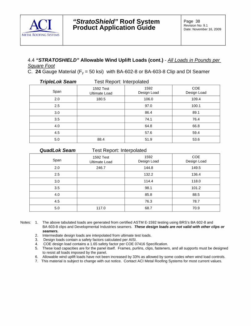
“StratoShield” Roof System Product Application Guide
Page 38 Revision No: 9.1 Date: November 16, 2009
4.4 “STRATOSHIELD” Allowable Wind Uplift Loads (cont.) - All Loads in Pounds per Square Foot C. 24 Gauge Material (Fy = 50 ksi) with BA-602-8 or BA-603-8 Clip and DI Seamer
TripleLok Seam Test Report: Interpolated
Span
1592 Test
Ultimate Load 1592
Design Load COE
Design Load
2.0 180.5 106.0 109.4
2.5 97.0 100.1
3.0 86.4 89.1
3.5 74.1 76.4
4.0 64.8 66.8
4.5 57.6 59.4
5.0 88.4 51.9 53.6
QuadLok Seam Test Report: Interpolated
Span
1592 Test
Ultimate Load 1592
Design Load COE
Design Load
2.0 246.7 144.8 149.5
2.5 132.2 136.4
3.0 114.4 118.0
3.5 98.1 101.2
4.0 85.8 88.5
4.5 76.3 78.7
5.0 117.0 68.7 70.9
Notes: 1. The above tabulated loads are generated from certified ASTM E-1592 testing using BRS’s BA 602-8 and BA 603-8 clips and Developmental Industries seamers. These design loads are not valid with other clips or
seamers. 2. Intermediate design loads are interpolated from ultimate test loads. 3. Design loads contain a safety factors calculated per AISI. 4. COE design load contains a 1.65 safety factor per COE 07416 Specification. 5. These load capacities are for the panel itself. Frames, purlins, clips, fasteners, and all supports must be designed
to resist all loads imposed by the panel. 6. Allowable wind uplift loads have not been increased by 33% as allowed by some codes when wind load controls. 7. This material is subject to change with out notice. Contact ACI Metal Roofing Systems for most current values.

“StratoShield” Roof System Product Application Guide
Page 39 Revision No: 9.1 Date: November 16, 2009
4.4 “STRATOSHIELD” Allowable Wind Uplift Loads (cont.) - All Loads in Pounds per Square Foot D. 24 Gauge Material (Fy = 50 ksi) with BA-602-12 or BA-603-12 Clip and DI Seamer
TripleLok Seam Test Report: Interpolated
Span
1592 Test
Ultimate Load 1592
Design Load COE
Design Load
2.0 217.6 127.8 131.9
2.5 116.8 120.5
3.0 102.6 105.8
3.5 87.9 90.7
4.0 76.9 79.3
4.5 68.4 70.6
5.0 105.0 61.5 63.6
QuadLok Seam Test Report: C1417-2
Span
1592 Test
Ultimate Load 1592
Design Load COE
Design Load
2.0 312 183.3 189.1
2.5 166.8 172.1
3.0 140.7 145.1
3.5 120.6 124.4
4.0 105.5 108.9
4.5 93.8 96.8
5.0 143.8 84.4 87.2
Notes: 1. The above tabulated loads are generated from certified ASTM E-1592 testing using BRS’s BA 602-12 and BA 603-12 clips and Developmental Industries seamers. These design loads are not valid with other clips or
seamers. 2. Intermediate design loads are interpolated from ultimate test loads. 3. Design loads contain a safety factors calculated per AISI. 4. COE design load contains a 1.65 safety factor per COE 07416 Specification. 5. These load capacities are for the panel itself. Frames, purlins, clips, fasteners, and all supports must be designed
to resist all loads imposed by the panel. 6. Allowable wind uplift loads have not been increased by 33% as allowed by some codes when wind load controls. 7. This material is subject to change with out notice. Contact ACI Metal Roofing Systems for most current values.

“StratoShield” Roof System Product Application Guide
Page 40 Revision No: 9.1 Date: November 16, 2009
4.4 “STRATOSHIELD” Allowable Wind Uplift Loads (cont.) - All Loads in Pounds per Square Foot E. 24 Gauge Material (Fy = 50 ksi) with BA-602-16 or BA-603-16 Clip and DI Seamer
TripleLok Seam Test Report: C1417-1
Span
1592 Test
Ultimate Load 1592
Design Load COE
Design Load
2.0 254.8 149.7 154.4
2.5 136.6 140.9
3.0 118.7 122.4
3.5 101.7 104.9
4.0 89.0 91.8
4.5 79.1 81.6
5.0 121.7 71.2 73.8
QuadLok Seam
Span
1592 Test
Ultimate Load 1592
Design Load COE
Design Load
2.0
2.5
3.0
3.5
4.0
4.5
5.0
Notes: 1. The above tabulated loads are generated from certified ASTM E-1592 testing using BRS’s BA 602-16 and BA 603-16 clips and Developmental Industries seamers. These design loads are not valid with other clips or
seamers. 2. Intermediate design loads are interpolated from ultimate test loads. 3. Design loads contain a safety factors calculated per AISI. 4. COE design load contains a 1.65 safety factor per COE 07416 Specification. 5. These load capacities are for the panel itself. Frames, purlins, clips, fasteners, and all supports must be designed
to resist all loads imposed by the panel. 6. Allowable wind uplift loads have not been increased by 33% as allowed by some codes when wind load controls. 7. This material is subject to change with out notice. Contact ACI Metal Roofing Systems for most current values.