Embed Size (px)
Citation preview

Strategies for Managing the Implications of Cycle-Driven Operating Patterns on Turbines and Generators
Rachel SweigartLead Consulting Engineer, TG Advisers
Stephen R. Reid, P.E.President and Principal Engineer, TG Advisers

Agenda• Today’s Energy Market• Impact of Operating Pattern• Case Studies
– Rotor Shaft Cracking– HP Casing Cracking– Generator End Block Failure– Introduction to Dynamic Intervals
Confidential © TG Advisers™ Inc. All Rights Reserved 2

Today’s Energy Market• Quicker starts, even on
vintage units• Ultra minimum loads (15-
20% load on nights/weekends)
• Two shift cycling• Repowering into
combined cycles• Life extensions of LP
components• Major outage extensions
Confidential © TG Advisers™ Inc. All Rights Reserved 3

Impacts of Changes in Operations• Increased number of
start/stops– Thermal transients– Low cycle fatigue cycles
• Damage is CUMULATIVE• Static inspection intervals may
no longer accurately reflect unit needs– Often based on years rather
than today’s operating profile– May not account for age and
accumulated service on unit
Confidential © TG Advisers™ Inc. All Rights Reserved 4

CASE STUDY 1: ROTOR SHAFT CRACKING
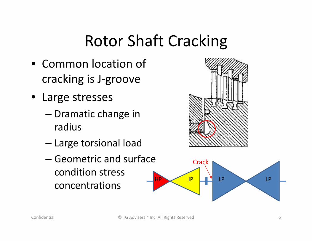
Rotor Shaft Cracking• Common location of
cracking is J-groove• Large stresses
– Dramatic change in radius
– Large torsional load– Geometric and surface
condition stress concentrations
Confidential © TG Advisers™ Inc. All Rights Reserved 6
HP IP LP LP
Crack

Rotor Shaft Cracking• 1980s unit was retrofitted in
2000• 5 years into operation unit
shutdown due to vibration– 50+ cycles – Shaft end was found “nearly
severed”• Solution
– Weld repaired– Polished and shot peened– Returned radius to as-designed
Confidential © TG Advisers™ Inc. All Rights Reserved 7
The end?

Rotor Shaft Cracking• Second failure occurs
– Clear NDE results 1 year prior– 22 cycles after NDE, cracking found– Cracking noted due to increased unit
vibration• Root cause analysis determined
sources:– LCF stresses amplified by surface
pitting leading to crack initiation– Eventual HCF propagation – Secondary influence from
misalignment
Confidential © TG Advisers™ Inc. All Rights Reserved 8
Issue was not completely addressed after 1st failure

Options for Management• Detection of flaws:
– Eddy Current Inspections– Shifts in critical speeds
• Preventative:– Proactive machining– Removes fatigued material, pitting– Shot peen new surface
• Address found issue:– Re-radii groove– Weld build up material and re-
machine groove– Stub shaft replacement
Confidential © TG Advisers™ Inc. All Rights Reserved 9
Many options depending on rotor condition

CASE STUDY 2: STEAM CHEST CRACKING

Steam Chest Cracking• Repowered unit operating as
part of a combined cycle • Duty cycle shifted toward
heavy cycling • Found cracking around control
valve seats in steam chest– Replica testing on crack
locations concluded cracking mode was fatigue
– No creep found• Reinspection interval was set
at “3-5 years”
Confidential © TG Advisers™ Inc. All Rights Reserved 11
Reinspection interval did not account for all factors

Steam Chest Cracking Analysis• Low cycle fatigue fracture
mechanics analysis was completed– Based on as-found crack sizes– Estimated material fracture
toughness– Assumed max stress to equal yield
strength• Estimated time to reach critical
crack size (including safety factor of 2) was >1,000 cycles
• Not recommended to grind cracks– Based on past history, cracks
reappeared in fresh surface
Confidential © TG Advisers™ Inc. All Rights Reserved 12

Case Study Conclusions• Steam chest cracking was not found to be the
limiting factor for establishing future re-inspection intervals for the unit– Analysis can evaluate whether action is needed on
cracking or not
• If duty cycle is further changed, analysis can be updated
Confidential © TG Advisers™ Inc. All Rights Reserved 13
Correct solution may be to take no corrective action
CASE STUDY 3: GENERATOR END BLOCK
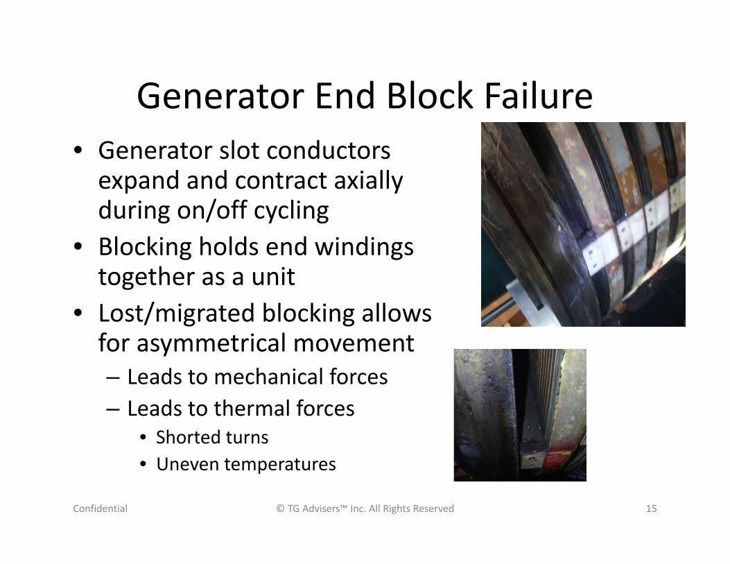
Generator End Block Failure• Generator slot conductors
expand and contract axially during on/off cycling
• Blocking holds end windings together as a unit
• Lost/migrated blocking allows for asymmetrical movement– Leads to mechanical forces– Leads to thermal forces
• Shorted turns• Uneven temperatures
Confidential © TG Advisers™ Inc. All Rights Reserved 15

Symptoms of Issue• High vibration on generator
– Limited base load operation– Vibration on unit correlated
with load and VARS
• Client noted movement in rotor end winding blocks and some blocks dropping from rotor
Confidential © TG Advisers™ Inc. All Rights Reserved 16

Generator End Block Failure• “Pop-rivet” type design end winding
blocking– Secures rotor end winding block to
rotor coil• RCA of end winding blocking
identified cause of failure in pop rivet flange as LCF from start/stop cycles over 1000
• Solution was modified end winding block and attachment design
Confidential © TG Advisers™ Inc. All Rights Reserved 17
Test for thermal sensitivity by varying MVars
Cracking

CASE STUDY 4: DYNAMIC INSPECTION INTERVALS

Case Study: Dynamic Inspection Intervals
• DFLP rotor • Cracking found in disc steeples
– Replications indicated fatigue – Steeples were re-radiused
• Re-inspection intervals were set based on operating hours– Re-inspection was occurring
multiple times between majors– Unit operational duty cycle
changed since hourly interval was established
Confidential © TG Advisers™ Inc. All Rights Reserved 19

Developing Dynamic Inspection Intervals• Based on unit specific analysis, not generic guidelines
– Allows for actual material properties to be used– Factors in results of prior inspection
• Correctly accounts for hours of operation, start-stop and overspeed cycles
• Appropriately credits or debits life based on actual operating conditions – Allows for impact of increased cycling and low load
operation on future maintenance costs to be assessed• Real time feedback on actual operation vs projected
Confidential © TG Advisers™ Inc. All Rights Reserved 20
Effectively & efficiently manage issues based on sound engineering analysis

Analysis DriversStress Corrosion Cracking• Operating Hours• Yield Strength• Temperature• Location of Wilson Line
Low Cycle Fatigue
• Frequency of Cycling• Stresses• Fracture Toughness
Confidential © TG Advisers™ Inc. All Rights Reserved 21

Base Loading Example
© TG Advisers™ Inc. All Rights Reserved 22
Cycles 100Hours 80,000Overspeeds 10
Inputs
Confidential

Cyclic Loading Example
© TG Advisers™ Inc. All Rights Reserved 23
Cycles 500Hours 10,000Overspeeds 10
Inputs
Confidential

LP Dynamic Inspection Intervals
© TG Advisers™ Inc. All Rights Reserved 24
NDE Minimum Detectable orCrack size found by NDE
Confidential

Case Study Conclusion
• Very different operating profiles can lead to the same cumulative effect
• Dynamic inspection intervals can efficiently manage issues with sound engineering practices
© TG Advisers™ Inc. All Rights Reserved 25Confidential

Questions?• TGA has accumulated over 200 case studies
associated with cycling and other failure modes• TGA welcomes any participant to join us at our
next training event
Confidential © TG Advisers™ Inc. All Rights Reserved 26
Feel free to contact us for advice on any turbine or generator issue (302) 691 – 330