Embed Size (px)
Citation preview

Strategic Synthetic Color Tuning of Oxadiazole Based Luminescent Organoboron
Compounds
A THESIS
SUBMITTED TO THE FACULTY OF THE GRADUATE SCHOOL
OF THE UNIVERSITY OF MINNESOTA
BY
Justin Wayne Hines
IN PARTIAL FULFILLMENT OF THE REQUIREMENTS
FOR THE DEGREE OF
MASTER OF SCIENCE
Prof. Paul Kiprof Adviser
May 2017

©Justin Wayne Hines 2017

i
Acknowledgements
I would first like to thank my advisor, Dr. Paul Kiprof, for his research support and
mentorship of the past two years. Much of what I have accomplished here at UMD is due
to his guidance and I greatly appreciate the time spent working in his lab and all I have
learned from him. I would also like to thank Dr. Venkatram Mereddy and Dr. Peter
Grundt for teaching me the tactics and fineness required for organic chemistry, as well as
the Mereddy group for their friendship and insights. In addition I would like to thank
Kevin Wielenberg, whom was invaluable assisting in the lab, and Brian Gute and
Romesh Lakhan who instructed me how to be an effective teacher. Finally I would like
to thank Cole Holestrom for his assistance with all the instrumentation for this project,
his support, and his friendship.

ii
I dedicate this to my wife Jessica and my children, Dallas and Shanty for their love and
support which made this achievement possible. I also dedicate this to my grandfather,
Miles, may he rest in peace knowing I fulfilled his lifelong dream.

iii
Abstract
Many organic dopants have been created for use in SMOLED displays, but few are
composed of a family of compounds that spans large portions of the visible spectrum.
Through careful design, a small family of simple oxadiazole based tetra-coordinated
organoboron compounds of the type B(N,O)X has been developed with emission that
spans the visible spectrum from violet to green. Oxadiazole based ligands were designed
and utilized for their potential for heteroatomic substitution as well as their excellent
electron transport properties. Significant changes in fluorescence were observed based
on the isomeric substitution of the naphthalene substituent. Minimal bathochromic
emission shifts were observed when the oxadiazole ligand was chelated with BPh2, as
well as minimal hypsochromic shifts when chelated to BF2. This evidence suggests the
emission of the complex is affected by the isomeric position and subsequent resonance of
the oxadiazole ligand. Boron clearly forms a dative bond with the lone pair from the
nitrogen on the oxadiazole ring. The data shows that this coordination is susceptible to
hydrolysis even with the addition of hydrophobic phenyl groups, due to the oxadiazole
ring’s inherent electron deficiency and affinity for hydrogen bonding. This is evident
especially in the boron trifluoride complex, in which the LCMS data shows the presence
of only one fluoride atom.

iv
Table of Contents
List of Figures v
List of Tables viii
Chapter 1 History and Applications of Boron 2
The Characteristics and Applications of Oxadiazole Compounds 4
Overview of LCD’s and OLED’s 6
Boron and Oxadiazole compounds for OLED Applications 11
Chapter 2
Synthesis and Development of New Boron Oxadiazole Complexes 16
Summary and Conclusions 21
Chapter 3
Experimental Details 24
Synthetic Methods 24
Bibliography 31
Appendix
UV-Vis Data 38
NMR Data 41
LC-MS Data 62

v
List of Figures
FIG 1 Common chiral alpha pinene derivatives 3
FIG 2 Biologically active benzoboroxoles 4
FIG 3 Oxadiazole Isomers 5
FIG 4 Various luminescent oxadiazole 6
FIG 5 Basic LCD pixel cross-section 7
FIG 6 The structure of a simple OLED 9
FIG 7 The relative energy states of the individual layers of a basic OLED 10
FIG 8 The Lewis acid base pairing of boron-nitride 12
FIG 9 The core of the ubiquitous BODIPY dye and the basic scaffold of a closely related
polydentate polypyridine dopant 13
FIG 10 Examples of the 2-pyridyl scaffold derivatives 14
FIG 11 Tuning of the quinolato core 15
FIG 12 Excitation and emission data for HPOP 38
FIG 13 Excitation and emission data for 1,2-HPON 38
FIG 14 Excitation and emission data for BPh2(1,2-PON) 39
FIG 15 Excitation and emission data for BF2(1,2-PON) 39
FIG 16 Excitation and emission data for BPh2(2,3-PON) 40
FIG 17 Excitation and emission data for BF2(2,3-PON) 40
FIG 18 1HNMR Methyl 4-Methoxy-2-Naphthoate 41

vi
FIG 19 1HNMR Methyl 4-Methoxy-2-Naphthoate 41
FIG 20 13CNMR Methyl 4-Methoxy-2-Naphthoate 42
FIG 21 1HNMR 4-Methoxy-2-Naphthohydrazide 42
FIG 22 1HNMR 4-Methoxy-2-Naphthohydrazide 43
FIG 23 13CNMR 4-Methoxy-2-Naphthohydrazide 43
FIG 24 1HNMR N'-benzoyl-4-methoxy-2-naphthohydrazide 44
FIG 25 1HNMR N'-benzoyl-4-methoxy-2-naphthohydrazide 45
FIG 26 13CNMR N'-benzoyl-4-methoxy-2-naphthohydrazide 45
FIG 27 1HNMR 2-(1-methoxynaphthalen-2-yl)-5-phenyl-1,3,4-oxadiazole 46
FIG 28 13CNMR 2-(1-methoxynaphthalen-2-yl)-5-phenyl-1,3,4-oxadiazole 47
FIG 29 1HNMR 1,2-HPON 48
FIG 30 1HNMR 1,2-HPON 48
FIG 31 13CNMR 1,2-HPON 49
FIG 32 C13NMR 1,2-HPON 49
FIG 33 1HNMR BF2(1,2-PON) 50
FIG 34 1HNMR BF2(1,2-PON) 51
FIG 35 13CNMR BF2(1,2-PON) 51
FIG 361HNMR Methyl 3-Methoxy-2-Naphthoate 52
FIG 37 1HNMR Methyl 3-Methoxy-2-Naphthoate 52
FIG 38 13CNMR Methyl 3-Methoxy-2-Naphthoate 53
vii
FIG 39 1HNMR N’-Benzoyl-3-Methoxy-2-Naphthohydrazide 53
FIG 40 1HNMR N’-Benzoyl-3-Methoxy-2-Naphthohydrazide 54
FIG 41 13CNMR N’-Benzoyl-3-Methoxy-2-Naphthohydrazide 54
FIG 42 1HNMR 2,3 HPON 55
FIG 43 1HNMR 2,3 HPON 55
FIG 44 13CNMR 2,3 HPON 56
FIG 45 13CNMR 2,3 HPON 57
FIG 46 1HNMR 2,3 BPH2(PON) (500 MHz, DMSO) 58
FIG 47 1HNMR 2,3 BPH2(PON) (500 MHz, DMSO) 59
FIG 48 1HNMR 2,3 BF2(PON) (500 MHz, DMSO) 60
FIG 49 1HNMR 2,3 BF2(PON) (500 MHz, DMSO) 60
FIG 50 13CNMR 2,3 BF2(PON) (500 MHz, DMSO) 61
FIG 51 LCMS BPh2(1,2-PON) 62
FIG 52 LCMS BPh2(1,2-PON) 63
FIG 53 LCMS BF2(1,2-PON) 64
FIG 54 LCMS BF2(1,2-PON) 65
FIG 55 LCMS BPh2(2,3-PON) 66
FIG 56 LCMS BPh2(2,3-PON) 67
FIG 57 LCMS BF2(2,3-PON) 68
FIG 58 LCMS BF2(2,3-PON) 69

viii
List of Tables
Table 1 Excitation and emission data for the oxadiazole ligands and oxadiazole complexes 23

ix
List of Schemes
Scheme 1 Synthetic route to benzoboroxole through reduction 17
Scheme 2 Proposed ring closing mechanism of benzoboroxole 17
Scheme 3 Synthesis of the oxadiazole ligands 19
Scheme 4 Chelation of the oxadiazole ligand to the boron compounds 21

x
Abbreviations
1,2 HPON 2-(5-phenyl-1,3,4-oxadiazol-2-yl)naphthalen-1-ol
2,3 HPON 3-(5-phenyl-1,3,4-oxadiazol-2-yl)naphthalen-2-ol
9BBN Banana Borane
Alq3 Aluminum Tris(8-Hydroxyquinolato)
BODIPY Boron Dipyrrin
DCM Dichloromethane
DMF Dimethylformamide
DMSO Dimethyl Sulfoxide
EDG Electron Donating Group
EML Emissive Materials Layer
ETL Electron Transport Layer
EWG Electron Withdrawing Group
HOMO Highest Occupied Molecular Orbital
HPOP 2-(5-phenyl-1,3,4-oxadiazol-2-yl)phenol
HTL Hole Transport Layer
ITO Indium Tin Oxide
LCD Liquid Crystal Display
LCMS Liquid Chromatography Mass Spectroscopy
LED Light Emitting Diode
LUMO Lowest Unoccupied Molecular Orbital
NMR Nuclear Magnetic Resonance Spectroscopy

xi
OLED Organic Light Emitting Diode
OTf Triflate
PHOLED Phosphorescent Light Emitting Diode
PLED Polymeric Light Emitting Diode
SMOLED Small Organic Light Emitting Diode
THF Tetrahydrofuran
TLC Thin Layer Chromatography
UMD University of Minnesota-Duluth
UV Ultra Violet
UV-Vis Ultra Violet Visible Spectrum

1
Aspects and overview
OLED technology has progressed greatly in recent years as the demand for
flexible displays, wider color variety, and better picture quality has increased. The
emissive materials themselves have been the primary focus of OLED research, as such
numerous materials have been researched and designed for that purpose. Boron
complexes and oxadiazoles have been used separately for organoluminescent materials,
but little research has been done to explore a combination of their unique characteristics.
The bulk of current luminescent organoboron compounds and oxadiazole compounds
were investigated in this paper. The materials researched were used in designing our own
ligands for such emissive materials. A new family of organoluminescent oxadiazole
boron complexes was designed with the overall goal of color tuning of the ligand. The
scope of this thesis is divided into three chapters: research and design, rationalization of
photophysical properties, and experimental. The development process of our luminescent
compounds with respect to what is known about organoboron compounds as well as
oxadiazole compounds in both present and past literature is covered in the first chapter of
this paper. The second chapter covers the investigation into the oxadiazole based ligand,
rationalization of luminescent properties and characterization of structural influences on
color tuning by use of NMR, UV-Vis, and LC-MS is presented. Finally, details of
experiments and procedures used are outlined in the third chapter.

2
Chapter 1
The History and Application of Boron
Boron was originally discovered in 1808 by Sir Humphry Davy, Joseph Louis Gay-
Lussac, and Louis Jacques Thenard. Davy termed the element boracium however it was
not officially discovered and recognized until 1828 by Jons Jako Berzelius. It wasn’t
until 1909 that the American chemist produced boron in its elemental form. 1,2
Boron is fairly rare, making up only .001% of the earth’s elemental mass. The majority of
boron containing ore deposits are found in Turkey, with the second largest deposit
residing in the United States. 3 The most common use for boron, by mass, is the
production of borosilicate glass from B2O3.4,5 Boron is extracted from naturally occurring
minerals, such as kernite and borax, and converted into boric acid. Pure boron is derived
from BBr3 under extreme conditions with H2, but is difficult due to impurities from
carbon and various other trace elements.5
Boron is widely used in industry and scientific research. It has applications ranging from
synthetic chemistry, medicinal uses, material science, and manufacturing. Since the
discovery of hydroboration, boron has been a cornerstone of organic chemistry.6 After the
first borohydride reagent with significant synthetic applications was discovered by Brown
and Krishnamurthy, hundreds of boron reagents have been developed. Many of the
reagents used today were developed by Brown himself.6,7 After the naturally occurring
alpha pinene’s properties as a chiral auxiliary for hydroboration were discovered, it has
been used for a wide range of reactions including but not limited to reduction,
hydroboration, homologation, enolboration, epoxide ring opening, and crotylboration all

3
of which are asymmetric and highly selective reactions FIG 1.8,9 Even the simplest of
boron reducing agents, sodium borohydride, can be coupled with a lanthanide to perform
highly selective reductions of alpha enones. This is more commonly referred to as Luche
Reduction.10 Possibly the most famous and most widely used boron reaction is the C-C
bond forming reaction known as Suzuki Coupling. With carefully designed palladium
catalysts, the sp2-sp2 and sp2-sp3 carbon bond forming reactions that were previously
impossible can almost indefinitely be achieved.11 The sheer number of synthetic
applications are too numerous and too broad in their potential applications to cover.
Fig 1 Common chiral alpha pinene derivatives for use in asymetric hydroboration (1,4),
asymmetric tosylation (2), asymmetric crotylation (3), and asymmetric homologation (5)
The medical applications of boron are well documented with new research broadening its
uses every day. New research into benzoboroxole derivatives has shown they exhibit
antibiotic,12 antifungal,13 antimalarial,14 and antiprotozoal15 drugs FIG 2. Boron has been
successfully used as an anticancer treatment in the form of B-10.16 This particular
treatment is highly selective but has shown difficulty in the delivery of the treatment
compounds to the affected areas in the necessary concentrations.16

4
FIG 2 Biologically active benzoboroxoles for use in antibiotics (1,2),12 antifungals
(2),12,13 antimalarial (3),14 and antiprotozoal (4)15 drugs.
In recent literature, boron has been incorporated and or materials designed around its
implementation in light harvesting photovoltaics,17,18 molecular switches,19,20 lasing
dyes,21 non-linear optics,22,23 biomolecular probes,24,25 chemosensors,26 energy transfer
cassettes,27 and superconductors.28,29
The majority of boron based chemosensors share many structural traits to boron based
OLED materials,26,30-32 Generally they manipulate the same properties of boron, namely
its empty pz orbital and natural Lewis acid character. Luminescent organoboron
compounds are highly sensitive to the coordination and electronic environment of the
boron, relying primarily on the conjugation of the system and the pπ-pπ* interactions
across boron’s empty orbital.33 Three coordinate boron systems readily form dative
bonds with strong electron donors such as fluorine, which drastically alter the overall
luminescent properties of the compound.26,31-34
Characteristics and Applications of Oxadiazole Compounds
Oxadiazoles are five membered heterocyclic compounds in the azole family, with three
stable isomers. The 1,2,4-isomer 1,3,5-isomer and 1,3,4-isomer are stable, however the

5
1,2,3-isomer undergoes ring opening forming the more stable diazoketone tautomer FIG
3.35
N
N
O
N N
O
N
N
O
N N
O
1 2 3 4
FIG 3 The 1,2,3-oxadiazole isomer (1), 1,2,4-oxadiazole isomer (2), 1,2,4-oxadiazole
isomer (3), and the 1,3,4-oxadiazole isomer(4).
Oxadiazoles are inherently electron deficient overall, yet the nitrogen atoms show Lewis
base characteristics similar to pyridine. These properties have been used with great
success in biomedical and material science applications.
A wide array of oxadiazole compounds have medicinal applications including
antifungal,36 antibacterial,37-39 antimicrobial,37-43 antiviral,45 anti-HIV,46
antitubercular,40,48 and anticancer43,45-49 pharmaceuticals with new research and
applications occurring worldwide. The heterocyclic nature of the oxadiazole rings allow
for high activity due to their ability to cross cell membranes efficiently allowing for
easier uptake into targeted cells.36-49
Oxadiazoles are excellent for material science field of optics such as nonlinear optics and
organic light emitting diodes due to their electron deficient nature.50 NLO is a broad
range of concepts and applications including data storage, optical communication, image
transmission, signal processing, data storage, and optical computing while OLEDs are

6
used primarily for flat panel displays in televisions, laptops, and cellphones.55-57
Oxadiazoles’ electron deficient nature makes them excellent electron transport
compounds and their luminescent properties can be easily tuned by modifying the
compounds overall electronic environment.50 This is typically done by extending the pi
system of the compound, such as increasing the overall conjugation of the system, or by
complexing the compound with a metal. Various metals have been used with oxadiazole
based compounds to great effect FIG4.50-54
N
NO
OH
1 2
N
NO
3
N
NO
N N
O
4
FIG 4 Various luminescent oxadiazole based compounds chelated with Iridium(1)51,
Aluminum(2)50, Biphenyl Boron(2)54, Cesium(3)52, and Tin(4)53 respectively.
Overview of LCD’s and OLED’s
Since the discovery and fabrication of the first practical OLED by Tang and Van Slyke
using the Alq3 complex,58 a wide array of organic compounds and devices have been
developed for their numerous advantages over modern LCD.59,60
7
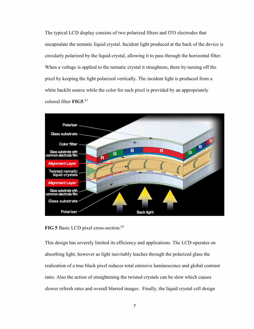
The typical LCD display consists of two polarized filters and ITO electrodes that
encapsulate the nematic liquid crystal. Incident light produced at the back of the device is
circularly polarized by the liquid crystal, allowing it to pass through the horizontal filter.
When a voltage is applied to the nematic crystal it straightens, there by turning off the
pixel by keeping the light polarized vertically. The incident light is produced from a
white backlit source while the color for each pixel is provided by an appropriately
colored filter FIG5.61
FIG 5 Basic LCD pixel cross-section.62
This design has severely limited its efficiency and applications. The LCD operates on
absorbing light, however as light inevitably leaches through the polarized glass the
realization of a true black pixel reduces total emissive luminescence and global contrast
ratio. Also the action of straightening the twisted crystals can be slow which causes
slower refresh rates and overall blurred images. Finally, the liquid crystal cell design

8
requires a rigid and thick structure when compared to an OLED. This prevents LCD’s
from various applications in which OLED’s excel such as semiconducting thin films.62
OLED devices overcome many of the short comings of LCD’s. Basic OLED’s consist of
three simple layers; electron transport layer, emissive material layer, and hole transport
layer. These layers are contained between two ITO and alloy electrodes FIG 6. These
layers are remarkably thin compared to an LCD, no more than 10nm each, which allows
for thinner and lighter displays. Each of these layers are specifically designed to so that
their semiconducting properties are compatible, in that the LUMO of the n-type ETL is
nearly isoenergetic with the EML. Without this compatibility the overall efficiency of
the device is drastically reduced to the resulting charge imbalance forcing the need for
higher voltages to operate the device. These principles also apply to HOMO of the p-
type semiconducting layer, or the hole transport layer. This design makes each OLED
unique in its composition and how the individual layers coordinate. In some instances,
based on composition and device architecture, additional layers may be required for
optimum efficiency and functionality. These additional layers are typically hole transport
blockers or electron blockers located next to the EML to prevent wide band gaps.
Materials that function as semiconductors and emissive materials are highly desirable to
decrease the number of layers needed for device function as well as reducing the exiplex
emission resulting from the interactions between different materials at their
interface.59,60,63-65
By design, OLED’s are operationally simplistic. Charges are injected in the HTL and
ETL FIG 7. Physicists commonly refer to these quasiparticles as polarons. This is
achieved by injecting electrons into the LUMO of the ETL or removing electrons from

9
the HTL. These polarons are driven by the applied voltage at the electrodes and as the
device is operated these polarons travel, or “hop” through the layers of the OLED to the
EML. Once they reach the EML they recombine resulting in photonic emission from the
device by charge recombination, unlike fluorescence which is typically a result of
electronic relaxation.59,60,63-65 The wave length of the emission corresponds to the
fluorescence band gap of the EML used.
FIG 6 The structure of a simple OLED66

10
FIG 7 The relative energy states of the individual layers of a basic OLED66.
Based on the broad range of semi-conducting materials available and wide variety of
fabrication methods OLED’s can range from flexible electronic displays to solid state
lighting. Depending on the materials and fabrication methods used OLED’s typically fall
into one of three categories: SMOLED, PLED, and PHOLED. From a fabrication and
manufacturing stand point SMOLED’s are more complex to produce because they rely on
doping via vapor deposition. However, this allows for endless synthetic possibilities for
creating new luminescent compounds. PLED devices are highly desirable because many
of the oligomeric chains are semi-conductive, allowing for less layers in the device.
Additionally, these polymer chains can easily be synthesized and fabricated into flexible
displays that are currently in high demand. PHOLEDs are a combination of SMOLEDs
and PLEDs, however the EML is comprised of a phosphorescent material instead of
11
fluorescent material. Due to the spin rules of phosphorescent charge combination,
emissions near quantum unity can be achieved.63-65
By design, OLEDs overcome many of the limitations of LCDs. Since the OLED operates
based on emission instead of absorption it is over all more energy efficient by eliminating
the need for a constant back light. They also can achieve a true black, which is another
major limitation in LCD devices. Because of the switch nature of OLED design it is able
to achieve better refresh rates. The wide array of OLED designs and composition allows
for higher chromaticity, contrast ratios, luminosity, as well as display size and
flexability.63-65
OLEDs do have certain limitations. Currently many have issues with low melting points
which cause the pixel to short out, moisture sensitivity leading to layer degradation, and
blue emissive materials have short lifetimes. Yet the sheer amount of potential material
design, architecture, and groundbreaking research insures that OLEDs will surpass
current LCD’s in the near future.59,60,63-65
This information is only a brief overview of OLED and LCD technology. There is a
massive collection of data and publications revolving around these technologies with far
more detailed information on their complex functionality and design.59-65
Boron and Oxadiazole Compounds for OLED Applications
As previously discussed, OLED devices rely on the π to π orbital interactions in the
organic semi-conductors to undergo the charge “hop” mechanism. This necessitates the
use of low band gap materials that are tunable for device fabrication. Based on these
parameters many boron based chelates have been research as alternatives to the

12
predominant transition metal based compounds. Their chemical nature has allowed for
the synthesis of many boron based emissive dopants that are easily tunable as EML type
compounds.66-73 Many of boron’s unique chemical properties have fueled its application
to OLED research. When in the ground state boron possesses three valence electrons,
and when in the binding state an s orbital and two p orbitals are combined into the sp2
hybridized trigonal planer geometry, while being two electrons short of an octet.74 This
causes boron to have a high ionization energy and covalent bond nature instead of the
trivalent nature of other similar elements.75 Donation of electron density into boron’s
empty p orbital can further shorten this covalent bond FIG 8.74,76
FIG 8 The Lewis acid base pairing of boron-nitride adducts results in shortening of the
bond distance (left); tetrahedral hybridization of boron (right)
Boron’s strong Lewis acidity stems from its empty pz orbital, allowing it to readily accept
two electrons through Lewis acid base pairing or dative bonding.5,77 A vast array of
organic chelates exploit this property for OLED applications due to its unique ability to
form a tetrahedral geometry when bound with a dative bond, thus locking extended π
systems into co-planarity for maximum π system overlap. This dative bonding is usually
with N,N or N,O chelates. The dative bonds ability to pseudo extend the conjugated π
system in this manner has been shown to enhance the photoluminescence of the

13
system.78,66 Organoboron compounds are widely used as ETL for their ability to easily
facilitate highly polarized charge transfer through boron’s pz orbital to π orbital
interactions.67
Boron’s covalent sigma bonding nature, due to its high charge density and small atomic
size, provides many advantages over its group 13 counterpart, aluminum.74 Boron
compounds are more stable than their aluminum or zinc counterparts due to this covalent
bonding.79-82 Thus, many numerous boron based derivatives of the Alq3 compound have
been made68-70,81,83-86, and these analogous boron compounds are what inspired our
development of new organoboron luminescent compounds. As previously stated there are
two main types of organoboron chelates; N,N type and N,O type.
Simple N,N type chelates are very popular presumably due to their easy chelation with
boron and the long term stability of the resulting compounds. Arguably the most famous
of these chelates the BODIPY dye and its numerous derivatives FIG 9.
FIG 9 The core of the ubiquitous BODIPY dye(right)87 and the basic scaffold of a closely related
polydentate polypyridine dopant(left)88,89
There are numerous publications and reviews on BODIPY and its derivatives describing
in detail various methods of color tuning. The use of BODIPY fluorophores in OLED’s

14
however many tridentate compounds similar to the BODIPY core have been synthesized
with OLED fabrication in mind.71-73,83,90-92 The most numerous of these are based on the
2-pyridyl scaffold FIG 10. Small modifications to the 2-pyridyl scaffold have led to a
wide variety of compounds with emission that span nearly all of the visible spectrum.72,73
Further tuning of the emissions were achieved by fluorination of the scaffold, however
the small changes in emission proved not to be cost effective based on the necessary
materials and methods of synthesis.72
FIG 10 Examples of the 2-pyridyl scaffold derivatives.72,73,91,92
Since Tang and Van Slyke’s synthesis of the aluminum tris-quinolate scaffold N,O-type
chelates have become the most popular and widely researched chelate with respect to
boron based OLED applications. Many of these BArq compounds have been synthesized
as dopants for EML, however given their versatility many have been designed into
emissive polymers69,83 and even dual functioning multinuclear ETL-EML materials.63
The two primary means of tuning the BArq compounds are extending the π conjugate
system and the use of EDG or EWG substituted on the quinolate core.65,66,85,86 Research
has shown that extending the conjugate π system or using EDG causes the emissions to

15
shift bathochromatically.70,85 The use of EWD causes the emissions to shift
hypsochromatically70,85 FIG 11.
FIG 11 Tuning of the quinolato core through means of π conjugate extension (1-3)85, and
through the use of various EDGs and EWGs on a polymeric scaffold (4)69.
Oxadiazoles are N,O-type ligands that have been recently studied for OLED applications.
Tang and Van Slyke extended their previous work with aluminum trisquinolate by
replacing the quinolate with an oxadiazole, which also formed a three coordinate
structure. Research into this new oxadiazole ligand, HPOP, showed promising results for
OLED applications when complexed with various metals FIG 4.50
16
These luminescent boron and oxadiazole based compounds have largely been the
influence for new OLED materials in our lab. I have extensively researched both
organoluminescent boron compounds as well as various oxadiazole compounds as a basis
for designing a new family of ligands for boron based OLED materials. Rationalization
of color tuning techniques have been successfully implemented from the literature in
producing new oxadiazole ligands for boron fluorophores with OLED type material
fabrication in mind.

17
Chapter 2
Synthesis and Development of New Boron-Oxadiazole Complexes
Our group’s interest in organic luminescent compounds began with benzoboroxole, a
heterocyclic polycycle that was first reported by Snyder in 1957.93 Benzoboroxole
consists of an aromatic six membered ring and a boron containing five membered
heterocycle. Shortly after its discovery, it was researched for its unique synthetic
characteristics and material applications.94-96 Benzoboroxole derivatives have been used
for antibiotic, antifungal, antimalarial, antiprotozoal pharmaceuticals, glycoconjugates,
Suzuki coupling, blue dyes, plastic biocides, and OLED materials.12-15,96 Recently
colleagues in Dr. Mereddy’s lab found a simple reaction to synthesize benzoboroxole
with consistent yields of 80 percent or more by reduction with sodium borohydride of the
corresponding 1,2-type substituted boronic acid-aldehyde Scheme 1.
Scheme 1 Synthetic route to benzoboroxole through reduction using sodium borohydride.
With the improved synthesis method, many research groups at UMD sought out new uses
for the benzoboroxole family. It was soon discovered that benzoboroxoles, like other
boron adducts, can be condensed with N,O-type ligands to form organoluminescent
compounds.96 This condensation uses boron’s Lewis acidity to exploit boronic acids
18
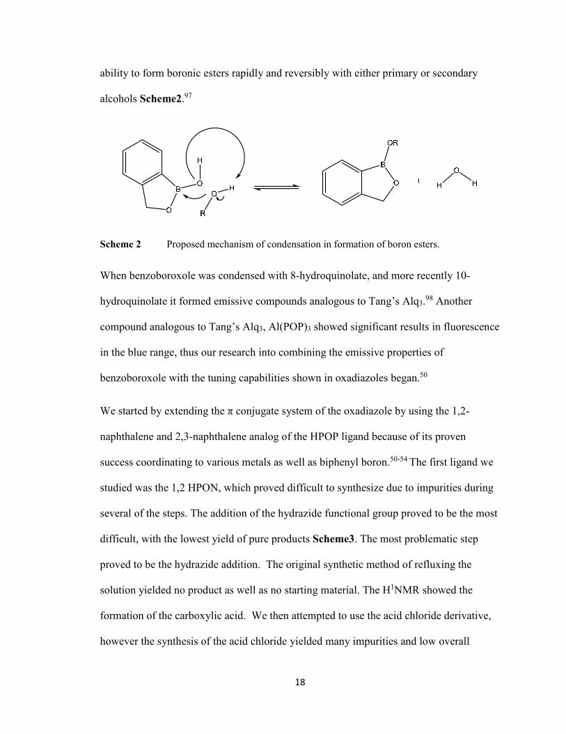
ability to form boronic esters rapidly and reversibly with either primary or secondary
alcohols Scheme2.97
Scheme 2 Proposed mechanism of condensation in formation of boron esters.
When benzoboroxole was condensed with 8-hydroquinolate, and more recently 10-
hydroquinolate it formed emissive compounds analogous to Tang’s Alq3.98 Another
compound analogous to Tang’s Alq3, Al(POP)3 showed significant results in fluorescence
in the blue range, thus our research into combining the emissive properties of
benzoboroxole with the tuning capabilities shown in oxadiazoles began.50
We started by extending the π conjugate system of the oxadiazole by using the 1,2-
naphthalene and 2,3-naphthalene analog of the HPOP ligand because of its proven
success coordinating to various metals as well as biphenyl boron.50-54 The first ligand we
studied was the 1,2 HPON, which proved difficult to synthesize due to impurities during
several of the steps. The addition of the hydrazide functional group proved to be the most
difficult, with the lowest yield of pure products Scheme3. The most problematic step
proved to be the hydrazide addition. The original synthetic method of refluxing the
solution yielded no product as well as no starting material. The H1NMR showed the
formation of the carboxylic acid. We then attempted to use the acid chloride derivative,
however the synthesis of the acid chloride yielded many impurities and low overall

19
yields. When the hydrazide addition was attempted, the product was an insoluble dimer
with naphthalene groups on each side. Then the original synthesis method was revisited
under the assumption that the refluxing process caused the hydrazine to evaporate before
the reaction could occur, despite the condenser apparatus. When mildly heated to 70º C
the reaction formed the desired product, however the yields were unreliable. It
consistently had a yield of 100% or more and the H1NMR showed a rapid hydrogen
transfer from residual water to the primary amine. There were many attempts to remedy
this occurrence, the used of desiccant in the condenser, molecular sieves in the solution,
drying in vacuo, recrystallization from various dry solvents, and even air drying. None of
these procedures removed the residual water, and the last two procedures actually
increased the water in the product. However, this residual water did not affect later
reactions although the following step’s yield calculation was skewed. Synthesis of the
2,3-HPON was much more efficient with higher yields and minimal purification required.
Scheme 3 Synthesis of 1,2-HPON Ligand, 2,3 HPON ligand follows the same scheme
We then attempted to tune the emissions with EDG and EWD in the 4 position of the
benzoboroxole’s six membered aromatic ring. Ultimately the benzoboroxoles did not
20
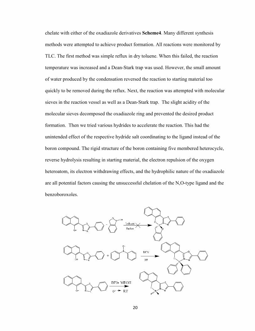
chelate with either of the oxadiazole derivatives Scheme4. Many different synthesis
methods were attempted to achieve product formation. All reactions were monitored by
TLC. The first method was simple reflux in dry toluene. When this failed, the reaction
temperature was increased and a Dean-Stark trap was used. However, the small amount
of water produced by the condensation reversed the reaction to starting material too
quickly to be removed during the reflux. Next, the reaction was attempted with molecular
sieves in the reaction vessel as well as a Dean-Stark trap. The slight acidity of the
molecular sieves decomposed the oxadiazole ring and prevented the desired product
formation. Then we tried various hydrides to accelerate the reaction. This had the
unintended effect of the respective hydride salt coordinating to the ligand instead of the
boron compound. The rigid structure of the boron containing five membered heterocycle,
reverse hydrolysis resulting in starting material, the electron repulsion of the oxygen
heteroatom, its electron withdrawing effects, and the hydrophilic nature of the oxadiazole
are all potential factors causing the unsuccessful chelation of the N,O-type ligand and the
benzoboroxoles.

21
Scheme 4 Chelation of the oxadiazole ligand to the boron compounds
Thus we moved on to other boron containing compounds. Again we used boron
compounds with EDG and EWD to tune the emissions. The synthesis of these complexes
were much more simplistic and efficient. Originally the reactions were performed in
THF at 0ºC and stirred to room temperature. This lead to a mixture of products and a
yield of 15% after purification. This is presumably due to the presence of moisture in the
THF. Next the reactions were run in DCM under the same conditions. Again, there were
similar results, presumably from high humidity or condensation accumulating inside the
flask. Finally the reaction was run in dry DCM at room temperature and stirred. Product
formation occurred in approximately 30 seconds by crashing out of solution. The
reaction was also observed under a UV light. This synthesis method had a yield of 80-
90% with high product purity.
The 1,2-HPON fluoresced at 458 nm, with a 38 nm difference between excitation and
emission peaks, while the 2,3-HPON is not fluorescent. When bound to diphenyl boron,
the 1,2-HPON diphenyl boron complex had strong emission at 466 nm with three
different excitation peaks resulting in various intensities of the same emission. This
pattern of multiple excitation peaks correlating to a single emission peak is consistent
with previously studied oxadiazole diphenyl boron.54 In the previous case HPOP was
complexed with diphenyl boron resulting in a similar excitation patter but an emission of
443 nm. This shows a minute bathochromic shift of approximately 20 nm by extending
the π system. In the case of the 1,2-HPON boron difluoride complex, again there were
multiple excitation peaks for the emission at 436 nm, all with varying intensities of the

22
emission. Thus the effectiveness of color tuning of the 1,2-HPON ligand was minimal
resulting in an emission shift of only 10-20 nm.
The 2,3-HPON ligand is not fluorescent on its own. When chelated with the diphenyl
boron it exhibited multiple excitation peaks with a single excitation peak at varying
intensities at 506 nm. When chelated with boron difluoride, it again showed multiple
excitation peaks of varying intensities at 492 nm. Again this shows that the electron
environment of the boron has little effect on the emission tuning of the complex.
Summary and Conclusions
Our research into new luminescent oxadiazole boron complexes has shown that the major
contributing aspect of tuning these new emissive compounds is the isomeric substitution
of the oxadiazole ligand and its resulting resonance. Through careful extension of the π
system of the oxadiazole ligand we have shown this causes a minimal bathochromic shift
of approximately 20nm on the overall fluorescence of the ligand as well as the boron
complexes. The original benzoboroxole oxadiazole complexes did not form. This could
be the result of many factors. The most likely causes are the oxadiazoles affinity for
hydrogen bonding preventing the removal of water from the reaction before it reverses
into the separate starting materials. It could also be caused by the oxygen atom in the
heterocyclic ring on the benzoboroxole removing too much electron density from the
boron combined with the inherent electron deficiency of the oxadiazole ring. However
the use of more simplistic boron compounds has shown clear tetra-coordinated boron
oxadiazole complexes with clear dative bond formation. The use of EWD and EDG on
the boron compound also show minimal cytochromatic and bathochromatic shifts of
approximately 10 nm respectively. These shifts were much smaller than anticipated. It

23
was assumed that the combination of π system augmentation and EDG would have a
more significant effect on the fluorescence. The distinct change in fluorescence of the
2,3-HPON when complexed with either boron compound shows the most efficient tuning
method lies in the substitution and resonance of the oxadiazoles extended conjugate
system Table1. These complexes proved to rapidly decompose in the presence of water,
even with the use of the hydrophobic diphenyl boron complex. This is most noticeable in
the boron difluoride complex where the LCMS spectra shows the presence on only one
fluoride atom due to decomposition from the minuscule amount of water in the solvent.
The loss of two mass units indicates the formation of a BFOH oxadiazole complex with
both the 1,2-HPON and 2,3 HPON ligands. Future research into this discovery will
include other isomers of the HPON and further extension of the π system as well as the
addition of more hydrophobic groups on the boron compounds to improve the
complexes’ stability in the presence of water.
Compound Name Excitation Wavelength (nm) Emission Wavelength (nm)
HPOP 387 458
BPh2(POP)(THF) 257,304,338,406 443
1,2-HPON 396 458
BPh2(1,2-PON) 326, 384, 425 468
BF2(1,2-PON) 314, 341, 381, 397 436
BPh2(2,3-PON) 326, 436 504
BF2(2,3-PON) 343, 407 492
Table 1 The excitation and emission data of the oxadiazole complexes

24
Chapter 3
NMR Spectroscopy
All spectra were taken on a Varian INOVA 500 MHz NMR spectrophotometer
maintained at 25 degrees Celsius operating at 500 MHz for 1H NMR and 126 MHz for
13C NMR. The deuterated solvent used for each respective spectrum is referenced to the
appropriate literature peak shift. Refer to the appendix for all experimental spectra.
UV-Vis Spectroscopy
UV-vis spectra were all taken at less than 1.0x10⁻⁵ M using a JASCO V-670
spectrophotometer with a 1 nm band pass, using toluene as the solvent.
LC-MS Spectroscopy
All LC-MS spectra were taken on a Thermo Ultimate 3000 & Bruker micro OTOF-QIII
using tetrahydrofuran as the solvent, with a concentration of 10 ppm.
Synthesis of Benzoboroxole
In a 500 mL round bottom flask at 0° C was added 2-formylphenylboronic acid
(5.0183 g, 33.4709 mmol) and methanol (250 mL). Sodium borohydride (1.381 g,
35.1445 mmol) was slowly added to the solution over a period of approximately 5
minutes. The mixture was then stirred and removed from the ice bath allowing the flask
to gradually warm to room temperature for a period of roughly 4 hours. With the
formation of various salts, the solution became cloudy. This was then acidified by drop
wise addition of HCl (3M, 5 mL) and extracted with ethyl acetate (3x20 mL). The

25
organic layer was then concentrated in vacuo to yield pure benzoboroxole (3.8285 g,
86.7% yield). Refer to the appendix for experimental data.
Synthesis of 6-Nitro-benzoboroxole
In a 50 mL round bottom flask at -40° C was added 25 ml of ≥90% fuming nitric acid.
The benzoboroxole (5.291 g, 40.01 mmol) was added over a period of 10 min while
stirring. A thick yellow/brown slurry was formed. The slurry was stirred at -40° C for 20
minutes. The slurry was added to 500 mL of ice water dropwise and stirred for 2 hours. A
fine white precipitate formed. The product was recovered by vacuum filtration and
washed (3 x 25 mL) with cold water. The resulting powder was allowed to air dry
overnight yielding pure 6-nitro-benzoboroxole (6.7417 g, 93% yield)
Synthesis of 6-Amino-benzoboroxole
In a 250 mL round bottom flask 6-nitro-benzoboroxole (5.0132 g, 28.016 mmol),
ammonium formate (8.83 g, 63.0599 mmol), palladium catalyst (1 g , 200mg Pd/C : 1 g
6-nitro-benzoboroxole) and anhydrous THF was stirred and allowed to reflux at 60°
Celsius for 3 hours. The yellow solution was filtered to remove the residual
palladium/carbon catalyst. The filtrate was concentrated in vacuo to yield reasonably
pure 6-amino-benzoboroxole as a fine yellow powder that was used without further
purification (3.3866 g, 81.2% yield).
Synthesis of 6-Dimethylamino-benzoboroxole
In a 50 mL round bottom flask 6-amino-benzoboroxole (270 mg, 1.812 mmol), potassium
carbonate (1.25 g, 9.064 mmol), and acetone (25 mL) was stirred while iodomethane
(0.33 mL, 5.438 mmol) was added dropwise. The reaction mixture was stirred for 30

26
minutes, then filtered to remover the potassium carbonate and washed with diethyl ether
(2 x 10 mL). The filtrate was dried with magnesium sulfate, then concentrated in vacuo to
produce pure 6-dimethylamino-benzoboroxole as an orange powder (300 mg, 93% yield).
Synthesis of Methyl 4-methoxy-2-naphthoate
In a 150 mL Erlenmeyer flask 1-hydroxy-2-naphthanoic acid (6.05 g, 32.15 mmol) and
DMF (50 mL) was stirred until the solid completely dissolved. Potassium carbonate
(16.57 g, 128.6 mmol) was added slowly to the solution as it stirred until the solution
stopped evolving gas. Dropwise over approximately 5 minutes iodomethane (10 mL,
160.75 mmol) was added to the solution and allowed to stir over night. The solution was
filtered to remove the remaining potassium carbonate, and the potassium carbonate was
washed with DMF (3 X 10 mL). The filtrate was then extracted with diethyl ether and
washed with cold water (5 X 20 mL), then dried over magnesium sulfate. The filtrate was
then concentrated in vacuo to produce a pure methyl-4-methoxy-2-naphthoate as a
viscous brown oil (5.94 g, 85% yield).
Synthesis of 4-methoxy-2-naphthohydrazide
In a 100 mL round bottom flask a mixture of methyl 4-methoxy-2-naphthoate (6.227 g,
28.796 mmol), hydrazine hydrate (6.4 mL, 55% N2H4), and ethanol (25 mL) was heated
to 70° Celsius with a condenser overnight. The solution was concentrated in vacuo
yielding reasonably pure, the primary impurity being water, 4-methoxy-2-
naphthohydrazide as a brown powder that was used without further purification (7.598 g,
yield almost quantitative, with some additional moisture in the compound).

27
Synthesis of N'-benzoyl-4-methoxy-2-naphthohydrazide
To a mixture of 4-methoxy-2-naphthohydrazide (7.598 g, 35.139 mmol) and pyridine
(100 mL) in a 250 mL flask cooled to 0° Celsius, was added benzoyl chloride (7.5 mL)
dropwise over approximately 20 minutes. The solution was stirred and kept cool for 2
hours, then allowed to stir at room temperature overnight. A creamy white precipitate
was obtained and collected after the solution was added to 500 mL of ice/water. The
precipitate was washed with water (3 x 25 mL), then allowed to air dry over 24 hours
yielding pure N'-benzoyl-4-methoxy-2-naphthohydrazide as a white powder (10.022g,
89% yield).
Synthesis of 2-(1-methoxynaphthalen-2-yl)-5-phenyl-1,3,4-oxadiazole
In a 250 mL round bottom flask N'-benzoyl-4-methoxy-2-naphthohydrazide (10.15 g,
32.371 mmol) and phosphoryl chloride (100 mL) was refluxed for 24 hours. The
resulting yellow solution was added to 500 mL of ice/water dropwise, producing a fine
white precipitate. The precipitate was recrystallized from ethanol producing pure 2-(1-
methoxynaphthalen-2-yl)-5-phenyl-1,3,4-oxadiazole as a fine white powder (6.74 g, 69%
yield).
Synthesis of 2-(5-phenyl-1,3,4-oxadiazol-2-yl)naphthalen-1-ol (1,2-HPON)
In a 100 mL round bottom flask 2-(1-methoxynaphthalen-2-yl)-5-phenyl-1,3,4-
oxadiazole (4.24 g, 14.024 mmol) was dissolved in 2,4,6-lutidiene (25 mL). Then lithium
iodide (95.63 g, 42.073 mmol) was added to the solution over a period of 2 minutes. The
solution was heated to reflux with a condenser column packed with Dryrite. Once at
reflux the condenser was sealed with a cap to minimize water exposure from the air. The

28
reaction was allowed to reflux for 24 hours. The resulting yellow solution and black
precipitate was acidified with hydrochloric acid (2M), yielding a fine grey precipitate.
The precipitate was recovered via filtration and washed with water (3 X 20 mL) yielding
pure 2-(5-phenyl-1,3,4-oxadiazol-2-yl)naphthalen-1-ol as a grey powder (3.881 g, 96%
yield).
Synthesis of 2-(1-((diphenylboranyl)oxy)naphthalen-2-yl)-5-phenyl-1,3,4-oxadiazole
In a 100 mL round bottom flask 2-(5-phenyl-1,3,4-oxadiazol-2-yl)naphthalen-1-ol (228
mg, 1 mmol) was dissolved in anhydrous THF. The solution was cooled to 0° C. Then
triphenyl boron: THF solution (0.25M, 4 mL) was added dropwise and stirred until the
reaction reached room temperature. After 2 hours pure 2-(1-
((diphenylboranyl)oxy)naphthalen-2-yl)-5-phenyl-1,3,4-oxadiazole was precipitated as a
pale yellow solid and filtered (0.3026 g, 66.8% yield).
Synthesis of 2-(1-((difluoroboranyl)oxy)naphthalen-2-yl)-5-phenyl-1,3,4-oxadiazole
In a 100 mL round bottom flask 2-(5-phenyl-1,3,4-oxadiazol-2-yl)naphthalen-1-ol (200
mg, .6936 mmol) was dissolved in DCM and cooled to 0° Celsius. Then a boron
trifluoride: methanol solution (14%, .08 mL) was added dropwise and stirred until room
temperature was reached. A tan precipitate was formed and filtered off, yielding pure 2-
(1-((difluoroboranyl)oxy)naphthalen-2-yl)-5-phenyl-1,3,4-oxadiazole as a fine tan
powder (0.187 g, 75.7% yield).
Synthesis of Methyl 3-methoxy-2-naphthoate
In the same manner as the synthesis of Methyl 4-methoxy-2-naphthoate, the reaction of
2-hydroxy-3-naphthanoic acid (1.00 g, 5.343 mmol) and iodomethane (0.66 mL, 26.716

29
mmol) was concentrated in vacuo yielding Methyl 3-methoxy-2-naphthoate as a viscous
brown oil (1.129 g, 97.8% yield). Refer to the appendix for experimental data.
Synthesis of 3-methoxy-2-naphthohydrazide
In the same manner as the synthesis of 4-methoxy-2-naphthohydrazide, the reaction of 3-
methoxy-2-naphthohydrazide (3.86 g, 17.850 mmol) and hydrazine (4 mL, 79.92 mmol)
was concentrated in vacuo yielding 3-methoxy-2-naphthohydrazide as a fine white
powder (3.73 g, 96.7% yield). Refer to the appendix for experimental data.
Synthesis of N'-benzoyl-3-methoxy-2-naphthohydrazide
In the same manner as the synthesis of N'-benzoyl-4-methoxy-2-naphthohydrazide, the
reaction of 3-methoxy-2-naphthohydrazide (1.681 g, 7.774 mmol) and benzoyl chloride
(1.68 mL, 11.951 mmol) was washed with water yielding pure N'-benzoyl-3-methoxy-2-
naphthohydrazide as a fine white powder (2.160 g, 87.2 % yield). Refer to the appendix
for experimental data.
Synthesis of 2-(1-methoxynaphthalen-2-yl)-5-phenyl-1,3,4-oxadiazole
In the same manner as the synthesis of 2-(1-methoxynaphthalen-2-yl)-5-phenyl-1,3,4-
oxadiazole, the reaction of Phosphoryl chloride (1.681 g, 7.774 mmol) and Phosphoryl
chloride (1.68 mL, 11.951 mmol) was washed with water yielding pure 2-(1-
methoxynaphthalen-2-yl)-5-phenyl-1,3,4-oxadiazole as a fine white powder (2.160 g,
87.2 % yield). Refer to the appendix for experimental data.

30
Synthesis of Synthesis of 3-(5-phenyl-1,3,4-oxadiazol-2-yl)naphthalen-2-ol (2,3HPON)
In the same manner as the synthesis of 1,2-HPON, 2-(1-methoxynaphthalen-2-yl)-5-
phenyl-1,3,4-oxadiazole (0.5057 g, 1.672 mmol) and Lithium Iodide (0.6716 g, 5.018
mmol) was reacted for 24 hours yielding 2,3-HPON (0.2142 g, .7429 mmol) as a fine
gray powder.
Synthesis of 3-(1-((diphenylboranyl)oxy)naphthalen-2-yl)-5-phenyl-1,3,4-oxadiazole
In the same manner of synthesis of 2-(1-((diphenylboranyl)oxy)naphthalen-2-yl)-5-
phenyl-1,3,4-oxadiazole, 2,3-HPON ( .2880 g, 1.0 mmol) was reacted with triphenyl
borane (0.25M, 4 mL) was reacted at RT yielding 2-(1-
((diphenylboranyl)oxy)naphthalen-2-yl)-5-phenyl-1,3,4-oxadiazole (0.3026 g, 66.8 %
yield) as a fine yellow powder.
Synthesis of 3-(1-((difluoroboranyl)oxy)naphthalen-2-yl)-5-phenyl-1,3,4-oxadiazole
In the same manner of synthesis as 2-(1-((difluoroboranyl)oxy)naphthalen-2-yl)-5-
phenyl-1,3,4-oxadiazole, 2,3-HPON (0.255 g, 0.8844 mmol) and trifluoroborane
methanol solution (14%, 0.113 mL) was added dropwise and reacted in methanol for 2
hours, yielding 3-(1-((difluoroboranyl)oxy)naphthalen-2-yl)-5-phenyl-1,3,4-oxadiazole
(0.125 g, 42.1 % yield)

31
Bibliography
(1) Weeks, M. E. In Discovery of the Elements; Kessinger Publishing Reprints, 1933;
p. 380.
(2) Laubengayer, A.; Hurd, D.; Newkirk, A.; Hoard, J. Journal of the American
Chemical Society 1943, 65, 1924-1931.
(3) Argust, P. Biological Trace Element Research 1998, 66, 131-143.
(4) The Economics of Boron; 11th ed.; Roskill Information Services Limited, 2006.
(5) Atkins, P.; Overton, T.; Rourke, J.; Weller, M.; Armstrong, F. Shriver & Atkins,
Inorganic Chemistry; 4th ed.; Oxford University Press: New York, 2006.
(6) Krishnamurthy, S.; Brown, H. Aldrichimica Acta 1979, 12, 1-12.
(7) Brown, H.; Krishnamurthy, S. Journal of the American Chemical Society 1974,
95, 1669.
(8) Brown, H.; Ramachandran, P. Journal of Organometallic Chemistry 1995, 500, 1-
19.
(9) Soundararajan, R.; Matteson, D. Journal of Organic Chemistry 1990, 55, 2274-
2275.
(10) Luche, J.; Gemal, A. Journal of the American Chemical Society 1981, 103, 5454-
5459
(11) Yin, L.; Liebscher, J. Chemical Reviews 2007, 107, 133-173.
(12) X. Hui, S.J. Baker, R.C Wester, S. Barbadillo, A. K. Cashmore, V. Sanders, K. M.
Hold, T. Akama, Y.-K. Zhang, J. J. Plattner, H. I. Maibach, J. Pharm. Sci. 2007, 96,
2622.
(13) a) S.J. Baker, C. Z. Ding, T. Akama, Y. K. Zhang, V. Hernandez, Y. Xia, Future
Med. Chem. 2009, 1, 1275;
b) Anacor Pharmacueticals, US 234981(A1)2006
(14) Y.-K. Zhang, J. J. Plattner, Y. R. Freund, E. E. Easom, Y. Zhou, L. Ye, H.
Wange, H. Cui. Bioorg. Med Chem. Lett. 2012, 22,1299.
(15) R.T. Jacobs, J. J. Plattner, B. Nare, S. A. Wring, D. Chen, Y. Freund, E. G.
Gaukel, M. D. Orr, J. B. Perales, M. Jenks, R. A. Noe, J. M. Sligar, Y. –K. Zhang, C. J.
Bacchi, N. Yarlett, R. Don, Future Med. Chem. 2011, 9, 199.
(16) Barth, R. F.; Coderre, J. A.; Vicente, M. G. H.; Blue, T. E. Clinical cancer
research 2005, 11, 39874002.
(17) Hattori, S.; Ohkubo, K.; Urano, Y.; Sunahara, H.; Nagano, T.; Wada, Y.;
Tkachenko, N. V.; Lemmetyinen, H.; Fukuzumi, S. The Journal of Physical Chemistry B
2005, 109, 15368-15375.
32
(18) Imahori, H.; Norieda, H.; Yamada, H.; Nishimura, Y.; Yamazaki, I.; Sakata, Y.;
Fukuzumi, S. Journal of the American Chemical Society 2001, 123, 100-110.
(19) Kollmannsberger, M.; Rurack, K.; Resch-Genger, U.; Daub, J. The Journal of
Physical Chemistry A 1998, 102, 10211-10220.
(20) Rao, Y.; Amarne, H.; Zhao, S.; McCormick, T. M.; MarOć, S.; Sun, Y.; Wang,
R.; Wang, S. Journal of the American Chemical Society 2008, 130, 12898-12900.
(21) Boyer, J. H.; Haag, A. M.; Sathyamoorthi, G.; Soong, M.; Thangaraj, K.;
Pavlopoulos, T. G. Heteroatom Chemistry 1993, 4, 39-49.
(22) Entwistle, C. D.; Marder, T. B. Angewandte Chemie International Edition 2002,
41, 2927-2931.
(23) Branger, C.; Lequan, M.; Lequan, R.; Large, M.; Kajzar, F. Chemical Physics
Letters 1997, 272, 265-270.
(24) Zeng, L.; Miller, E. W.; Pralle, A.; Isacoff, E. Y.; Chang, C. J. Journal of the
American Chemical Society 2006, 128, 10-11.
(25) Killoran, J.; Allen, L.; Gallagher, J. F.; Gallagher, W. M.; OShea, D. F. Chem.
Commun. 2002, 18621863.
(26) Kubo, Y.; Yamamoto, M.; Ikeda, M.; Takeuchi, M.; Shinkai, S.; Yamaguchi, S.;
Tamao, K. Angewandte Chemie International Edition 2003, 42, 2036-2040.
(27) Burghart, A.; Thoresen, L. H.; Chen, J.; Burgess, K.; Bergström, F.; Johansson, L.
B. Chem. Commun. 2000, 2203-2204.
(28) Murata, N.; Haruyama, J.; Reppert, J.; Rao, A. M.; Koretsune, T.; Saito, S.;
Matsudaira, M.; Yagi, Y. Phys. Rev. Lett. 2008, 101.
(29) Gajewski, W.; Achatz, P.; Williams, O. A.; Haenen, K.; Bustarret, E.; Stutzmann,
M.; Garrido, J. A. Phys. Rev. B 2009, 79.
(30) Yamaguchi, S.; Akiyama, S.; Kohei, T. Journal of the American Chemical Society
2001, 123, 1137211375.
(31) Cui, Y.; Li, F.; Lu, Z.; Wang, S. Dalton Trans. 2007, 2634.
(32) Sun, Y.; Wang, S. Inorganic Chemistry 2009, 48, 3755-3767.
(33) Yamaguchi, S.; Shirasaka, T.; Akiyama, S.; Tamao, K. Journal of the American
Chemical Society 2002, 124, 8816-8817.
(34) Zhao, S.; McCormick, T.; Wang, S. Inorganic Chemistry 2007, 46, 10965-10967.
(35) John A. Joule; Keith Mills, Heterocyclic Chemistry, 2013, 842.
(36) P. Sengupta, M. Mal, S. Mandal, J. Singh, T. K. Maity, Iranian Journal of
Pharmacology and Therapeutics, vol. 7, no. 2, pp. 165-167, 2008.

33
(37) A. A. Kadi, N. R. El-Brollosy, O. A. Al-Deeb, E. E. Habib, T. M. Ibrahim, A. A.
El-Emam, European Journal of Medicinal Chemistry, vol. 42, no. 2, pp. 235-242, 2007.
(38) N. Bhardwaj, S. K. Saraf, P. Sharma, P. Kumar, E-Journal of Chemistry, vol. 6,
no. 4, pp. 1133-1138, 2009.
(39) M. A. Bakht, M. S. Yar, S. G. Abdel-Hamid, S. I. Al Qasoumi, A. Samad,
European Journal of Medicinal Chemistry, vol. 45, no. 12, pp. 5862-5869, 2010.
(40) M. J. Ahsan, J. G. Samy, H. Khalilullah et al., Bioorganic and Medicinal
Chemistry Letters, vol. 21, no. 24, pp. 7246-7250, 2011.
(41) M. J. Ahsan, J. Sharma, S. Bhatia, P. K. Goyal, K. Shankhala, M. Didel, Letters
in Drug Design and Discovery, vol. 11, no. 4, pp. 413-419, 2013.
(42) G. C. Ramaprasad, B. Kalluraya, B. Sunil Kumar, S. Mallya, Medicinal
Chemistry Research, vol. 22, no. 11, pp. 5381-5389, 2013.
(43) Suman Bala, Sunil Kamboj, Anu Kajal, Vipin Saini, Deo Nanadan Prasad,
BioMed Research International, vol. 2014
(44) T. Akhtar, S. Hameed, N. A. Al-Masoudi, R. Loddo, P. L. Colla, Acta
Pharmaceutica, vol. 58, no. 2, pp. 135-149, 2008.
(45) M. Khan, T. Akhtar, N. A. Al-Masoudi, H. Stoeckli-Evans, and S. Hameed,
Medicinal Chemistry, vol. 8, no. 6, pp. 1190-1197, 2012.
(46) Salahuddin, M. Shaharyar, A. Majumdar, M. J. Ahsan, Arabian Journal of
Chemistry, 2013.
(47) M. J. Ahsan, J. G. Samy, C. B. Jain, K. R. Dutt, H. Khalilullah, and M. S.
Nomani, Bioorganic and Medicinal Chemistry Letters, vol. 22, no. 2, pp. 969-972, 2012.
(48) M. J. Ahsan, R. V. P. Singh, M. Singh et al., Medicinal Chemistry, vol. 33, no. 3,
pp. 294-297, 2013.
(49) Ahsan, Mohamed Jawed, et al. BioMed Research International, 2014
(50) Wang, J. F., Jabbour, G. E., Mash, E. A., Anderson, J., Zhang, Y., Lee, P. A.,
Armstrong, N. R., Peyghambarian, N. and Kippelen, B. Adv. Mater. 1999, 11: 1266–
1269.
(51) Lianqing Chen, Han You, Chuluo Yang, Dongge Ma, Jingui Qin. Chem. Commun.,
2007, 1352–1354
(52) Jiun-Haw Lee a, Meng-Hsiu Wu, Chun-Chieh Chao, Hung-Lin Chen, Man-Kit
Leung. Chemical Physics Letters 416. 2005. 234–237
(53) Janghouri, Mohammad; Mohajerani, Ezeddin; Amini, Mostafa M, Najafi,
Ezzatollah; Hosseini, Hadi. Journal of Electronic Materials, 42,10, 2013. 2915-2925.
(54) Ruipig Deng, Leijiao Li, Mingxing Song, Shuna Zhao, Liang Zhao, Shuan Yoa.
The Royal Society of Chemistry 20, 2016. 1-11

34
(55) Shivashankar, Sunitha M., Vishnumurthy K. Anantapadmanabha, Airody
Vasudeva Adhikari. Polymer Engineering and Science 53.6 2013
(56) G.D.L. Torre, P. Vazquez, F. Agullo-Lopez, and T. Torres, Chem. Rev., 104, 3723
2004.
(57) D. Udayakumar and A.V. Adhikari, Synth. Met., 156. 1168. 2006
(58) Tang, C.; VanSlyke, S. Applied Physics Letters 1987, 51, 913-915.
(59) Kulkarni, A. P.; Tonzola, C. J.; Babel, A.; Jenekhe, S. A. Chemistry of Materials
2004, 16, 45564573.
(60) Hughes, G.; Bryce, M. R. J. Mater. Chem. 2005, 15, 94.
(61) Boer, W. D. Active Matrix Liquid Crystal Displays; Newnes: Oxford, 2005
(62) Physical Properties of Liquid Crystals: Nematics; Dunmur, D.; Fukuda, A.;
Luckhurst, G., Eds.; Inspec/Iee: London, 2001.
(62) www.nakan-tech.cp.jp <http://www.nakan-
techno.co.jp/en/technology/glossary.html> 2 March 2016
(63) Kafafi, Z. Organic Electroluminescence; CRC Press, Taylor & Francis Group:
Boca Raton, 2005.
(64) Kalinowski, J. Organic Light-Emitting Diodes: Principles, Characteristics, and
Processes; Marcel Dekker: New York, 2005.
(65) Organic Light-Emitting Materials and Devices; Li, Z.; Meng, H., Eds.; CRC
Press, Taylor & Francis Group: Boca Raton, 2007.
(66) Wakamiya, A.; Mori, K.; Yamaguchi, S. Angew. Chem. Int. Ed. 2007, 46, 4273-
4276.
(66) Craig Freudenrich, Ph.D. "How OLEDs Work" 24 March 2005.
HowStuffWorks.com. <http://electronics.howstuffworks.com/oled.htm> 2 March 2016
(67) Jia, W.; Song, D.; Wang, S. The Journal of Organic Chemistry 2003, 68, 701-705.
(68) Cui, Y.; Wang, S. The Journal of Organic Chemistry 2006, 71, 6485-6496.
(69) Qin, Y.; Kiburu, I.; Shah, S.; Jakle, F. Macromolecules 2006, 39, 9041-9048.
(70) Qin, Y.; Kiburu, I.; Shah, S.; Jakle, F. Organic Letters 2006, 8, 5227-5230.
(71) Liu, S.; Wu, Q.; Schmider, H. L.; Aziz, H.; Hu, N.; Popovic, Z.; Wang, S. Journal
of the American Chemical Society 2000, 122, 3671-3678.
(72) Liu, Q.; Mudadu, M. S.; Thummel, R.; Tao, Y.; Wang, S. Advanced Functional
Materials 2005, 15, 143-154.
(73) Chen, H.; Chi, Y.; Liu, C.; Yu, J.; Cheng, Y.; Chen, K.; Chou, P.; Peng, S.; Lee,
G.; Carty, A.; Yeh, S.; Chen, C. Advanced Functional Materials 2005, 15, 567-574.

35
(74) Cotton, F.; Wilkinson, G. Advanced Inorganic Chemistry; 5th ed.; John Wiley
and Sons Inc: New York, 1998.
(75) Muetterties, E. The Chemistry of Boron and Its Compounds; John Wiley and Sons
Inc: New York, 1967.
(76) Hirao, H.; Fujimoto, H. The Journal of Physical Chemistry A 2000, 104, 6649-
6655.
(77) Kotz, J.; Treichel Jr., P. Chemistry and Chemical Reactivity; 4th ed.; Saunders
College Publishing: Orlando, 1996.
(78) Wakamiya, A.; Taniguchi, T.; Yamaguchi, S. Angew. Chem. Int. Ed. 2006, 45,
3170-3173.
(79) Park, N. G.; Lee, J.; Park, Y. H.; Kim, Y. S. Synthetic Metals 2004, 145, 279-283.
(80) Wang, S. Coordination Chemistry Reviews 2001, 215, 79-98.
(81) Wu, Q.; Esteghamatian, M.; Hu, N.; Popovic, Z.; Enright, G.; Tao, Y.; D'Iorio,
M.; Wang, S. Chem. Mater. 2000, 12, 79-83.
(82) Anderson, S.; Weaver, M. S.; Hudson, A. J. Synthetic Metals 2000, 111, 459-463.
(83) Nagata, Y.; Chujo, Y. Macromolecules 2008, 41, 3488-3492.
(84) Ugolotti, J.; Hellstrom, S.; Britovsek, G. J. P.; Jones, T. S.; Hunt, P.; White, A. J.
P. Dalton Trans. 2007, 1425.
(85) Kappaun, S.; Rentenberger, S.; Pogantsch, A.; Zojer, E.; Mereiter, K.; Trimmel,
G.; Saf, R.; Möller, K. C.; Stelzer, F.; Slugovc, C. Chem. Mater. 2006, 18, 3539-3547.
(86) Cui, Y.; Liu, Q.; Bai, D.; Jia, W.; Tao, Y.; Wang, S. Inorganic Chemistry 2005,
44, 601-609
(87) Loudet, A.; Burgess, K. Chemical Reviews 2007, 107, 4891-4932.
(88) Yang, G.; Su, T.; Su, Z.; Zhang, H.; Wang, Y. J. Phys. Chem. A 2007, 111, 2739-
2744.
(89) Zhang, H.; Huo, C.; Ye, K.; Zhang, P.; Tian, W.; Wang, Y. Inorganic Chemistry
2006, 45, 2788-2794.
(90) Liddle, B. J.; Silva, R. M.; Morin, T. J.; Macedo, F. P.; Shukla, R.; Lindeman, S.
V.; Gardinier, J. R. The Journal of Organic Chemistry 2007, 72, 5637-5646.
(91) Cheng, C.; Yu, W.; Chou, P.; Peng, S.; Lee, G.; Wu, P.; Song, Y.; Chi, Y. Chem.
Commun. 2003, 2628.
(92) Liu, Q.; Mudadu, M. S.; Schmider, H.; Thummel, R.; Tao, Y.; Wang, S.
Organometallics 2002, 21, 4743-4749.
(93) Snyder, H.; Reedy, A.; Lennarz, W. Journal of the American Chemical Society
1958, 80, 835-838.

36
(94) Haynes, R.; Snyder, H. Journal of Organic Chemistry 1964, 29, 3229-3233.
(95) Cummings, W.; Cox, C.; Snyder, H. Journal of Organic Chemistry 1969, 34,
1669-1674.
(96) Gunasekera, D. S.; Gerold, D. J.; Aalderks, N. S.; Chandra, J. S.; Maanu, C. A.;
Kiprof, P.; Zhdankin, V. V.; Reddy, M. V. R. Tetrahedron 2007, 63, 9401-9405.
(97) Brown, H.; Bhat, N.; Somayaji, V. Organometallics 1983, 2, 1311-1316.
(98) Robin, B.; Buell, G.; Kiprof, P.; Nemykin, V. Acta Crystallographica Section E
E64, o314-o315.

37
Appendix
All supporting experimental spectra and data are presented there within. Data is presented
as per section of experiment; refer to the table of contents for pagination of material
provided.

38
UV-Vis Spectroscopy and Fluorescence Spectroscopy
FIG 12 Excitation and emission data for HPOP
FIG 13 Excitation and emission data for 1,2-HPON
0
50
100
150
200
250
300
350
200 300 400 500 600
Inte
nsi
ty (
a.u
).
Wavelength (nm)
HPOP
Excitation
458nm
Emission 387nm
0
100
200
300
400
500
600
700
800
250 300 350 400 450 500 550 600
Inte
nsi
ty (
a.u
)
Wavelength (nm)
1,2-HPON
Excitation 458nm
Emission 396nm

39
FIG 14 Excitation and emission data for BPh2(1,2-PON)
FIG 15 Excitation and emission data for BF2(1,2-PON)
0
100
200
300
400
500
600
700
800
900
250 300 350 400 450 500 550 600 650
Wavelength (nm)
1,2 HPON BPh2 Complex
Excitation 466nm
Emission 326nm
Emission 384nm
Emission 425nm
0
100
200
300
400
500
600
700
800
900
1000
250 300 350 400 450 500 550 600
Inte
nsi
ty (
a.u
)
Wavelength (nm)
1,2 HPON BF3 Complex
Excitation
Emission 314nm
Emission 341nm
Emission 381nm
Emission 397nm

40
FIG 16 Excitation and emission data for BPh2(2,3-PON)
FIG 17 Excitation and emission data for BF2(2,3-PON)
0
100
200
300
400
500
600
700
800
900
250 300 350 400 450 500 550 600 650
Inte
nsi
ty(a
.u)
Wavelength(nm)
2,3 HPON BPh2 Complex
Excitation 506nm
Emission 346nm
Emission 424nm
0
50
100
150
200
250
300
350
250 300 350 400 450 500 550 600 650
Inte
nsi
ty (
a.u
)
Wavelength (nm)
2,3 HPON BF3 Complex
Excitation 492nm
Emission 343nm
Emission 407nm

41
NMR Spectroscopy
FIG 18 1HNMR Methyl 4-Methoxy-2-Naphthoate (500 MHz, CDCl3) δ 8.297, 8.279, 7.876,
7.858, 7.844, 7.629, 7.610, 7.592, 7.577, 7.563, 4.072, 3.988
FIG 19 1HNMR Methyl 4-Methoxy-2-Naphthoate (500 MHz, CDCl3) δ 8.297, 8.279, 7.876,
7.858, 7.844, 7.629, 7.610, 7.592, 7.577, 7.563, 4.072, 3.988

42
FIG 20 13CNMR Methyl 4-Methoxy-2-Naphthoate (500 MHz, CDCl3) δ 166.693, 158.393,
136.859, 128.651, 128.414, 127.972, 126.751, 126.629, 123.693, 119.283, 63.422, 52.27
FIG 21 1HNMR 4-Methoxy-2-Naphthohydrazide (500 MHz, CDCl3) δ 9.054, 8.760, 7.913,
7.869, 7.753, 7.737, 7.542, 7.527, 7.512, 7.418, 7.403, 7.388, 7.222, 4.231, 4.071, 4.056

43
FIG 22 1HNMR 4-Methoxy-2-Naphthohydrazide (500 MHz, CDCl3) δ 9.054, 8.760, 7.913,
7.869, 7.753, 7.737, 7.542, 7.527, 7.512, 7.418, 7.403, 7.388, 7.222, 4.231, 4.071, 4.056
FIG 23 13CNMR 4-Methoxy-2-Naphthohydrazide (500 MHz, CDCl3) δ 163.924, 161.918,
156.235, 137.011, 132.282, 131.534, 128.735, 128.399, 128.247, 127.369, 127.316, 126.835,
126.088, 124.844, 123.197, 119.001, 63.834

44
FIG 24 1HNMR N'-benzoyl-4-methoxy-2-naphthohydrazide (500 MHz, CDCl3) δ 8.355, 8.349,
8.344, 8.337, 8.326, 8.222, 8.220, 8.204, 8.203, 8.168, 8.165, 8.155, 8.151, 8.149, 8.142, 7.93,
7.788, 7.770, 7.753, 7.653, 7.651, 7.645, 7.639, 7.633, 7.627, 7.625, 7.619, 7.581, 7.578, 7.562,
7.548, 7.286, 7.268, 7.190, 7.174, 7.170, 7.165, 4.206, 4.205, 4.204, 4.201, 4.195, 4.194, 4.188,
4.187, 4.185, 4.161, 4.160

45
FIG 25 1HNMR N'-benzoyl-4-methoxy-2-naphthohydrazide (500 MHz, CDCl3) δ 8.355, 8.349,
8.344, 8.337, 8.326, 8.222, 8.220, 8.204, 8.203, 8.168, 8.165, 8.155, 8.151, 8.149, 8.142, 7.93,
7.788, 7.770, 7.753, 7.653, 7.651, 7.645, 7.639, 7.633, 7.627, 7.625, 7.619, 7.581, 7.578, 7.562,
7.548, 7.286, 7.268, 7.190, 7.174, 7.170, 7.165, 4.206, 4.205, 4.204, 4.201, 4.195, 4.194, 4.188,
4.187, 4.185, 4.161, 4.160
FIG 26 13CNMR N'-benzoyl-4-methoxy-2-naphthohydrazide (500 MHz, CDCl3) δ 163.924,
161.918, 156.235, 137.011, 132.282, 131.534, 128.735, 128.399, 128.247, 127.369, 127.316,
126.835, 126.088, 124.844, 123.197, 119.001, 63.834

46
FIG 27 1HNMR 2-(1-methoxynaphthalen-2-yl)-5-phenyl-1,3,4-oxadiazole (500 MHz, CDCl3) δ
8.316, 8.309, 8.304, 8.299, 8.206, 8.196, 8.144. 8.141, 8.127, 8.124, 7.905, 7.898, 7.895, 7.891,
7.888, 7.748, 7.731, 7.616, 7.611, 7.608, 7.600, 7.597, 7.562, 7.552. 7.542, 7.529, 4.328

47
FIG 28 13CNMR 2-(1-methoxynaphthalen-2-yl)-5-phenyl-1,3,4-oxadiazole (500 MHz, CDCl3) δ
164.687, 163.253, 156.105, 136.378, 131.710, 129.124, 129.070, 128.292, 128.147, 126.950,
126.919, 125.218, 124.707, 124.066, 123.937, 123.258, 112.960, 63.071

48
FIG 29 1HNMR 1,2-HPON (500 MHz, CDCl3) δ 11.142, 8.498, 8.482, 8.189, 8.177, 8.174,
7.845, 7.831, 7.817, 7.628, 7.628, 7.614, 7.599, 7.590, 7.575, 7.560, 7.545, 7.488, 7.471
FIG 30 1HNMR 1,2-HPON (500 MHz, CDCl3) δ 11.142, 8.498, 8.482, 8.189, 8.177, 8.174,
7.845, 7.831, 7.817, 7.628, 7.628, 7.614, 7.599, 7.590, 7.575, 7.560, 7.545, 7.488, 7.471

49
FIG 31 13CNMR 1,2-HPON (500 MHz, DMSO) δ 155.51, 135.719, 132.023, 129.132, 128.781,
127.576, 126.805, 126.104, 124.387, 123.357, 123.098, 121.557, 119.879, 101.083, 101.068.
FIG 32 C13NMR 1,2-HPON (500 MHz, DMSO) δ 155.51, 135.719, 132.023, 129.132, 128.781,
127.576, 126.805, 126.104, 124.387, 123.357, 123.098, 121.557, 119.879, 101.083, 101.068.

50
FIG 33 1HNMR BF2(1,2-PON)(500 MHz, DMSO) δ 11.264, 8.363, 8.347, 8.189, 8.186, 8.174,
8.170, 7.992, 7.979, 7.975, 7.964, 7.694, 7.681, 7.667, 7.663, 7.648, 7.630, 7.627, 7.616.
FIG 34 1HNMR BF2(1,2-PON)(500 MHz, DMSO) δ 11.264. 8.363, 8.347, 8.189, 8.186, 8.174,
8.170, 7.992, 7.979, 7.975, 7.964, 7.694, 7.681, 7.667, 7.663, 7.648, 7.630, 7.627, 7.616.

51
FIG 35 13CNMR BF2(1,2-PON)(500 MHz, DMSO) δ 164.817, 163.245, 154.740, 136.043,
132.755, 129.956, 129.460, 128.377, 127.309, 126.996, 124.517, 123.479, 123.357, 123.045,
120.611, 102.380

52
FIG 36 1HNMR Methyl 3-Methoxy-2-Naphthoate (500 MHz, CDCl3) δ8.282, 7.788, 7.771,
7.705, 7.688, 7.495, 7.481, 7.467, 7.465, 7.355, 7.342, 7.328, 7.168, 3.956, 3.949, 3.940, 2.854,
2.847, 2.829
FIG 37 1HNMR Methyl 3-Methoxy-2-Naphthoate (500 MHz, CDCl3) δ 8.282, 7.788,
7.771, 7.705, 7.688, 7.495, 7.481, 7.467, 7.465, 7.355, 7.342, 7.328, 7.168, 3.956, 3.949,
3.940, 2.854, 2.847, 2.829
53
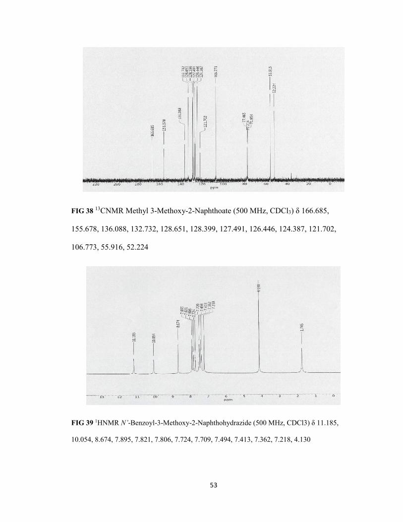
FIG 38 13CNMR Methyl 3-Methoxy-2-Naphthoate (500 MHz, CDCl3) δ 166.685,
155.678, 136.088, 132.732, 128.651, 128.399, 127.491, 126.446, 124.387, 121.702,
106.773, 55.916, 52.224
FIG 39 1HNMR N’-Benzoyl-3-Methoxy-2-Naphthohydrazide (500 MHz, CDCl3) δ 11.185,
10.054, 8.674, 7.895, 7.821, 7.806, 7.724, 7.709, 7.494, 7.413, 7.362, 7.218, 4.130

54
FIG 40 1HNMR N’-Benzoyl-3-Methoxy-2-Naphthohydrazide (500 MHz, CDCl3) δ 11.185,
10.054, 8.674, 7.895, 7.821, 7.806, 7.724, 7.709, 7.494, 7.413, 7.362, 7.218, 4.130
FIG 41 13CNMR N’-Benzoyl-3-Methoxy-2-Naphthohydrazide (500 MHz, CDCl3) δ 160.262,
154.450, 136.035, 133.983, 132.274, 131.511, 129.193, 128.765, 128.178, 127.308, 126.401,
124.837, 119.543, 106.781, 56.312

55
FIG 42 1HNMR 2,3 HPON (500 MHz, DMSO) δ aromatic multiplet peaks ranging 8.46-7.36
FIG 43 1HNMR 2,3 HPON (500 MHz, DMSO) δ aromatic multiplet peaks ranging 8.46-7.36

56
FIG 44 13CNMR 2,3 HPON (500 MHz, DMSO) δ 64.023, 163.825, 153.100, 136.485, 132.465,
129.437, 128.819, 128.728, 128.613, 127.507, 127.217, 126.546, 124.502, 123.266, 111.755,
110.733

57
FIG 45 13CNMR 2,3 HPON (500 MHz, DMSO) δ 64.023, 163.825, 153.100, 136.485, 132.465,
129.437, 128.819, 128.728, 128.613, 127.507, 127.217, 126.546, 124.502, 123.266, 111.755,
110.733

58
FIG 46 1HNMR 2,3 BPH2(PON) (500 MHz, DMSO) δ 9.920, 8.423, 8.288, 8.127, 8.119, 8.114,
7.831, 7.813, 7.751, 7.736, 7.724, 7.684, 7.670, 7.684, 7.623, 7.60, 7.648, 7.623, 7.600, 7.557,
7.530, 7.527, 7.519, 7.503, 7.442, 7.361, 7.340, 7.312, 7.300, 7.283, 7.256, 7.239, 7.227, 7.211,
7.142, 7.127, 7.113, 7.111, 7.069, 7.057

59
FIG 47 1HNMR 2,3 BPH2(PON) (500 MHz, DMSO) δ 9.920, 8.423, 8.288, 8.127, 8.119, 8.114,
7.831, 7.813, 7.751, 7.736, 7.724, 7.684, 7.670, 7.684, 7.623, 7.60, 7.648, 7.623, 7.600, 7.557,
7.530, 7.527, 7.519, 7.503, 7.442, 7.361, 7.340, 7.312, 7.300, 7.283, 7.256, 7.239, 7.227, 7.211,
7.142, 7.127, 7.113, 7.111, 7.069, 7.057

60
FIG 48 1HNMR 2,3 BF2(PON) (500 MHz, DMSO) δ 10.537, 8.767, 8.302, 8.153, 8.032, 7.958,
7.813, 7.696, 7.589, 7.552, 3.489, 2.640, 1.643, 1.487
FIG 49 1HNMR 2,3 BF2(PON) (500 MHz, DMSO) δ 10.537, 8.767, 8.302, 8.153, 8.032, 7.958,
7.813, 7.696, 7.589, 7.552, 3.489, 2.640, 1.643, 1.487

61
FIG 50 13CNMR 2,3 BF2(PON) (500 MHz, DMSO) δ 164.275, 163.848, 153.153, 136.325,
132.641, 130.909, 130.726, 129.971, 129.040, 128.941, 127.515, 127.210, 124.578, 123.754,
112.876, 70.166, 47.510, 26.533
62
LCMS Spectroscopy
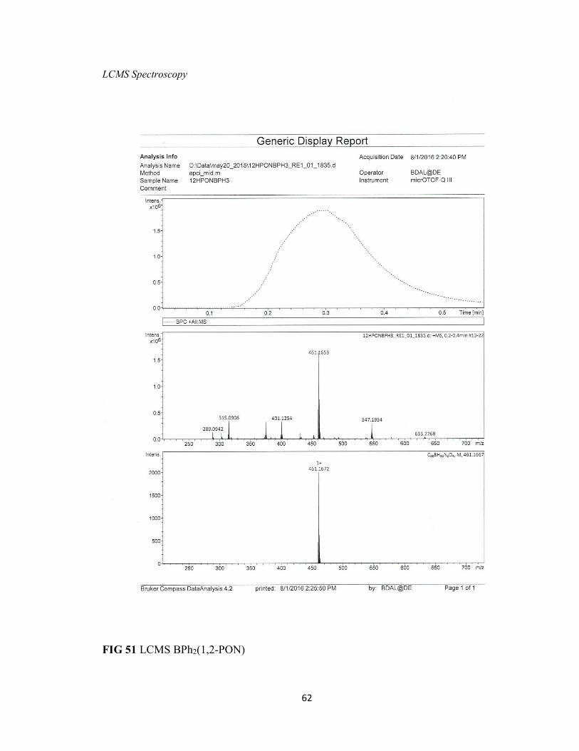
FIG 51 LCMS BPh2(1,2-PON)
63
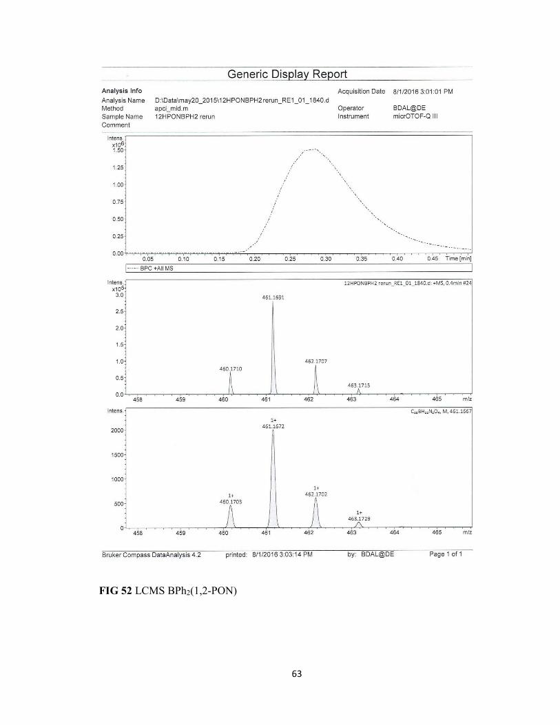
FIG 52 LCMS BPh2(1,2-PON)
64
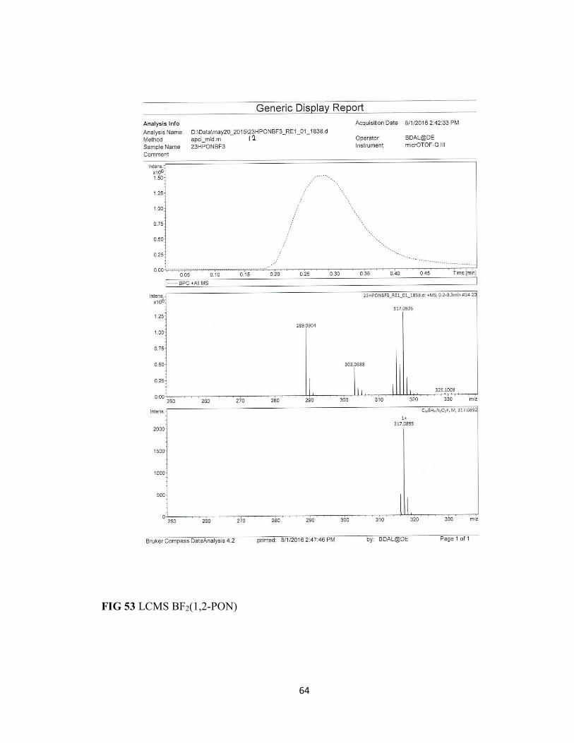
FIG 53 LCMS BF2(1,2-PON)

65
FIG 54 LCMS BF2(1,2-PON)

66
FIG 55 LCMS BPh2(2,3-PON)

67
FIG 56 LCMS BPh2(2,3-PON)

68
FIG FIG 57 LCMS BF2(2,3-PON)
69
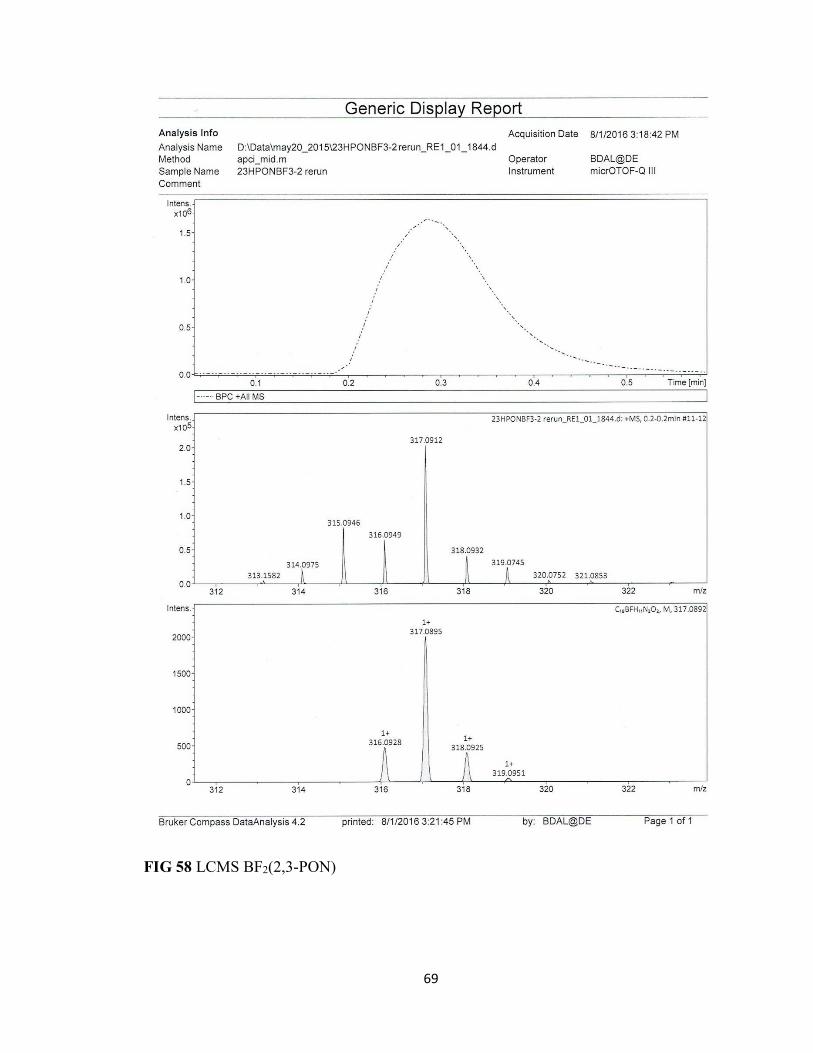
FIG 58 LCMS BF2(2,3-PON)


![Pyrazole-oxadiazole Conjugates: Synthesis, …Pyrazole-oxadiazole Conjugates: Synthesis, Antiproliferative Activity and Inhibition of Tubulin Polymerization Ahmed Kamal, *[a,d] Anver](https://img.dokumen.tips/doc/110x75/5e8c65afba3d737ddc66773e/pyrazole-oxadiazole-conjugates-synthesis-pyrazole-oxadiazole-conjugates-synthesis.jpg)