Embed Size (px)
Citation preview

STRANTROL® SET POINT CONTROLLER
INSTALLATION, OPERATION &
MAINTENANCE MANUAL


Table of Contents
General Guidelines ................................................................................................................... i
Warning Notifications............................................................................................................. ii
Mounting/Plumbing ............................................................................................................... 1 Mounting the Controller.......................................................................................................1 Wrapping the Fittings ...........................................................................................................1 Assembling the Flowcell ........................................................................................................1 Plumbing the Sample Stream ................................................................................................1 Opening the Sample Stream..................................................................................................2 Plugging in the Sensors .........................................................................................................2
Part I: Electrical .................................................................................................................... 3 Power Terminals ...................................................................................................................3 Connecting Power to the Power Cords .................................................................................3 Opening the Cover ...............................................................................................................4 Wiring Directly to the Unit ..................................................................................................4 Setting the Line Voltage Switch ............................................................................................5 Wiring Relays........................................................................................................................5 Wiring Relay 1......................................................................................................................6 Wiring Relay 2 (dry contact) .................................................................................................7 Wiring Relay 2 (powered) ....................................................................................................8 Placing the Power Jumper “CN15” ......................................................................................9 Wiring Relay 3......................................................................................................................9 Wiring a Flow Switch............................................................................................................9
Part II: DIP Switch and Jumper Settings ............................................................................ 10 Setting the DIP Switch........................................................................................................10 Setting the Jumpers .............................................................................................................10 Choosing Feed Up or Feed Down.......................................................................................10 Time-based Proportional Control .......................................................................................10 ON/OFF control ................................................................................................................11 Setting the Failsafe Timer Settings ......................................................................................11 Replacing the Cover ............................................................................................................11
Part III: Programming.......................................................................................................... 13 Entering the Program Menu ...............................................................................................13 Setting the pH High Alarm Point .......................................................................................13 Setting the pH Low Alarm Point.........................................................................................13 Setting HRR High Alarm Point ..........................................................................................13 Setting HRR Low Alarm Point ...........................................................................................14 Exiting the Menu ................................................................................................................14 Displaying Set Point............................................................................................................14 Modifying the Set Point ......................................................................................................14 Single Point Calibration......................................................................................................15 Resetting the Failsafe Alarm ................................................................................................15
Part IV: Maintenance ........................................................................................................... 17 Cleaning the Sensors ...........................................................................................................17
Appendix A Flow Switch Installation ....................................................................................... i
Appendix B Feed Charts and Typical Installations ................................................................... i


General Guidelines
i
How you choose to install and use your STRANTROL® Controller depends in part on your needs and specific applications. This manual offers a general guideline that is suitable for the majority of users. As an overview, we suggest that you first mount the components, i.e., the Controller, Flowcell, HRR sensor, and pH sensor. Then plumb the sample stream, open valves and test for leaks. Finally wire everything properly and program the controller. Your shipping package should contain these items: 1. The STRANTROL Set Point Controller and Warranty Registration Form. 2. HRR Sensor (P/N 7042002). 3. pH Sensor (P/N 7040004). 4. Flowcell Kit. CAUTION: Handle the HRR and pH Sensors carefully! They will break if dropped on a hard surface. The tips must be kept wet at all times, so leave the shipping caps in place until you are ready to install.

Warning Notifications
ii
NOTE: PLEASE PAY PARTICULAR ATTENTION TO THE WARNING NOTICES FOUND ON THE FOLLOWING PAGES AND THROUGHOUT THIS MANUAL. NEVER OVERRIDE SAMPLE FLOW SWITCH TEST FLOW SWITCH FUNCTION NEVER CONNECT FEEDER DIRECTLY TO POWER SOURCE
Flow switches are provided with allStrantrol controllers and are an integralsafety device to prevent theuncontrolled feed of chemicals, whichcould cause personal injury or death.The flow switch should NEVER bebypassed, even temporarily, as thiscritical safety device will not beavailable to protect the swimmers.
If flow switch does not initiate a No Flowalarm during backwash, no-flow, or very lowflow conditions, the controller cannot preventthe uncontrolled feed of chemicals, whichcould cause personal injury or death. Testing of the flow switch installation isessential to assure the flow switch andcontroller shows “NO-FLOW ALARM” within20 seconds, whenever filter is in backwash orcirculation flow stops. If the flow switch doesnot initiate a No Flow alarm, plumbingcorrections or the installation of additionalsafeguards will be necessary to avoiduncontrolled chemical feed.
If the chemical feeders are connected to awall outlet, the safety devices integral toyour Strantrol controller, and to the safefeeding of chemicals, will be bypassed. It isvery important that the chemical feeders areconnected to the controller and never to awall outlet. If the chemical feeders areconnected to a wall outlet and feedingcontinuously, when the flow of water to thepool stops due to filter backwash, thecirculation pump losing prime or othercauses, potentially hazardousconcentrations of chemicals can be fed intopool or spa.

Warning Notifications
iii
ALWAYS USE ANTI-SIPHON DEVICES ELECTRICAL SURGES CAN DAMAGE YOUR CONTROLLER
WARNING REGARDING CIRCULATION PUMP INTERLOCK
Strantrol controllers, like all modern electronic devices can be damaged by severe electrical spikes and surges (think ‘lightning’). Every effort has been made to harden your Strantrol controller against such surges, but no precautions are 100% effective. Additional surge protection can be installed at time of installation, but even that is not a guarantee that surge damage will not occur. If surge damage occurs, chemicals could be fed to your pool or spa continuously, with no safety controls. If you inspect your Strantrol after a possibly damaging power surge (thunderstorm or power outage) and suspect the controller is not operating properly, disconnect the chemical feeders at once, and contact your Strantrol dealer for service.
If concentrated Chlorine and Acid arecombined, chlorine gas is released. Chlorinegas causes severe irritation to lungs and can betoxic in certain situations. If water is not flowing in the return line to thepool, and both these concentrated chemicalsare allowed to combine in still water, a chlorinegas bubble will be created. When the floweventually resumes to the pool, the chlorinebubble would then be flushed into the pool andreleased into the air around the pool, beginningat the water surface. To help prevent thissituation, a chemical pump interlock must beinstalled. An interlock removes power from thechemical feed pumps whenever the power tothe recirculation pump power is switched off.
If a vacuum is created in the watercirculation line and no anti-siphon device isinstalled on the chemical feeders,potentially hazardous concentrations ofchemicals can be drawn into pool or spa.Always use injection check valves and anti-siphon valves in the chemical feed lines toprevent this situation from occurring.
Warning Notifications
iv
WARNING REGARDING DISCONNECTING POWER CONNECTION WARNING REGARDING CONNECTING pH & CHLORINE OR BROMINE FEEDERS
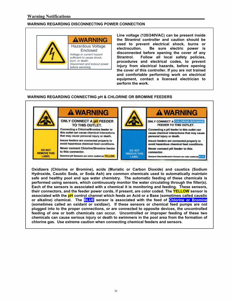
Line voltage (120/240VAC) can be present inside the Strantrol controller and caution should be used to prevent electrical shock, burns or electrocution. Be sure electric power is disconnected before opening the cover of any Strantrol. Follow all local safety policies, procedures and electrical codes, to prevent injury from electrical hazards, before opening the cover of this controller. If you are not trained and comfortable performing work on electrical equipment, contact a licensed electrician to perform the work.
Oxidizers (Chlorine or Bromine), acids (Muriatic or Carbon Dioxide) and caustics (SodiumHydroxide, Caustic Soda, or Soda Ash) are common chemicals used to automatically maintainsafe and healthy pool and spa water chemistry. The automatic feeding of these chemicals isperformed using sensors, which continuously monitor the water circulating through the filter(s).Each of the sensors is associated with a chemical it is monitoring and feeding. These sensors,their connectors, and the feeder power cords, if present, are color coded. The YELLOW sensor isassociated with the pH control channel which feeds an Acid or a Base (sometimes called causticor alkaline) chemical. The BLUE sensor is associated with the feed of Chlorine or Bromine(sometimes called an oxidant or oxidizer). If these sensors or chemical feed pumps are notplugged into to the proper connections, or are connected to opposite devices, the uncontrolledfeeding of one or both chemicals can occur. Uncontrolled or improper feeding of these twochemicals can cause serious injury or death to swimmers in the pool area from the formation ofchlorine gas. Use extreme caution when connecting chemical feeders and sensors.

Part I: Mounting/Plumbing
1
Mounting the Controller
Make sure that the Set Point controller and the flowcell are mounted in a location that is free from chemical fumes and excessive heat, isolated from electrical interference, and near a power source protected by a ground fault interrupter. Do not install Set Point controller out of doors. Wrapping the Fittings
If you are assembling a flowcell, first open the bag of flowcell fittings and wrap each fitting three times around clockwise with Teflon® tape.
Assembling the Sample Stream
The drawing below shows the flowcell parts that are provided with the Set Point controller. Once you have finished assembling the flowcell, close the valves and check for leaks.
NOTE: PARTS REPRESENTED BY DASHED LINES ARE NOT PROVIDED.
DESCRIPTION
SCREW, FLAT HD., #10-32 x 3/4" LG.
BUSHING, PVC, 1/2" x 1/4", TxT
BODY, FLOWCELL ASSY w/INSERTS
SCREW, PAN HD., #10-32 x 3/4" LG.
5O-RING, FLOWCELL
1312
1011
98
67
VALVE, 1/4" LABCOCKFLOWSWITCH
PLUG, PVC, 1/2"PLUG, PVC, 1/4"
PROBE, ORPPROBE, pH
KEY
4321
COVER, FLOWCELL
BRACKET, FLOWCELL
16091205
95760127821003
6720002
70400046720004
77722127042002
777251211
4411
12
PART NO.1570008
19300051690511
2961023 1
111
QTY
BUSHING, PVC, 3/4" x 1/2", SxT 1932010 2
14
Plumbing the Sample Stream (Refer to Appendix A)
Before installing the sensors, give them a light cleaning with a toothbrush and detergent (see Part V). Wrap the sensor threads six times around clockwise with Teflon tape. Also, before installing the pH sensor (yellow), shake it down like a thermometer to get air out of the tip.
Save the sensor caps for future sensor storage.
The flow switch is provided with two (2) slip x thread reducer bushings. Using the proper PVC primer and glue, assemble the flow switch with a reducer bushing on each end. Pay particular attention to the flow direction indicated on the switch, and install only in “Bottom to Top”, or horizontal direction; never the “Top to Bottom” orientation.

Part I: Mounting/Plumbing
2
Note: As soon as you install the sensor, move immediately on to the next step to ensure that it stays wet.
If flow switch does not initiate a No Flow alarm during backwash, no-flow, or very low flow conditions, the controller cannot prevent the uncontrolled feed of chemicals, which could cause personal injury or death. Opening the Sample Stream Valve
Open the sample stream valve and check for leaks. Once you have a positive and steady pressure, open the wet test valve and make sure it generates a vigorous stream. Plugging in the Sensors
Plug the pH sensor into the yellow-coded BNC jack and the HRR sensor into the blue-coded jack on the bottom of the Set Point by twisting them a quarter of a turn. Allow the sensors to rinse in the sample water while you do the wiring (Part II). (Flowcell parts represented with dashed lines are not provided.)
Oxidizers (Chlorine or Bromine), acids (Muriatic or Carbon Dioxide) and caustics (Sodium Hydroxide, Caustic Soda, or Soda Ash) are common chemicals used to automatically maintain safe and healthy pool and spa water chemistry. The automatic feeding of these chemicals is performed using sensors, which continuously monitor the water circulating through the filter(s). Each of the sensors is associated with a chemical it is monitoring and feeding. These sensors, their connectors, and the feeder power cords, if present, are color coded. The YELLOW sensor is associated with the pH control channel which feeds an Acid or a Base (sometimes called caustic or alkaline) chemical. The BLUE sensor is associated with the feed of Chlorine or Bromine (sometimes called an oxidant or oxidizer). If these sensors or chemical feed pumps are not plugged into to the proper connections, or are connected to opposite devices, the uncontrolled feeding of one or both chemicals can occur. Uncontrolled or improper feeding of these two chemicals can cause serious injury or death to swimmers in the pool area from the formation of chlorine gas. Use extreme caution when connecting chemical feeders and sensors.

Part II: Electrical
3
Power Terminal
There are two options to connect power to the unit:
1) Plug directly into a power source using the male power cord (see next paragraph);
OR
2) Open the unit and discard the power cords and wire directly to the unit. Option 2 will require that you provide insulated spade connectors to attach the power to the spade lugs on the Set Point controller.
NOTE: There is no need to open the cover to connect power and a chemical feeder as this may be done through the power cords provided (see next step). If you are using AC output and intend on using the controller to control one chemical feeder or act as a monitor and alarm, this is the easiest and fastest way to wire the unit. You must open the cover, however, to connect the Flow Switch.
Line voltage (120/240VAC) can be present inside the Strantrol controller and caution should be used to prevent electrical shock, burns or electrocution. Be sure electric power is disconnected before opening the cover of any Strantrol. Follow all local safety policies, procedures and electrical codes, to prevent injury from electrical hazards, before opening the cover of this controller. If you are not trained and comfortable performing work on electrical equipment, contact a licensed electrician to perform the work. Connecting Power to the Power Cords
If the chemical feeders are connected to a wall outlet, the safety devices integral to your Strantrol controller, and to the safe feeding of chemicals, will be bypassed. It is very important that the chemical feeders are connected to the controller and never to a wall outlet. If the chemical feeders are connected to a wall outlet and feeding continuously, when the flow of water to the pool stops due to filter backwash, the circulation pump losing prime or other causes, potentially hazardous concentrations of chemicals can be fed into pool or spa.

Part II: Electrical
4
The Set Point controller is protected by a fuse against a load in excess of .25 amps for electronics, and 3 amps for each relay. It must be plugged into an earth-grounded AC power source. If you choose this option, you may plug directly into a 110 volt power source and go to Step 11. NOTE: If you are using a 220 volt power source, you must go to Step 11 to change the line voltage switch before you plug in the unit. (Not normally needed in North America.) Opening the Cover
If you chose not to use the power cords to provide power to the unit, you must open the cover to connect power. Remove the cover by loosening the four screws at the corners with a screwdriver as shown. NOTE: The screws do not need to be totally removed, but only loosened. Once the screws are loosened, carefully lift the top cover off of the unit. For now set aside the moisture absorbent packet found inside. NOTE: Be sure to store the cover in a safe, dry place while you wire the unit. Wiring Directly to the Unit
If you choose to wire direct to the unit and discard the cords, you may use the two ½-inch holes in the casing enclosure to enable you to easily run conduit. Use insulated spade crimps provided. Connect the black wire to spade lug labeled “LINE - CN1”, connect the green wire to the spade lug labeled “EARTH - CN2”, and connect the white wire to the spade lug labeled “NEUTRAL - CN3” inside the base of the unit. Use the ½-inch cord grips provided and whatever holes are convenient, but when you are finished wiring the unit, be sure to plug any unused holes with a ½-inch NEMA 4 (IP65) plug.
Line voltage (120/240VAC) can be present inside the Strantrol controller and caution should be used to prevent electrical shock, burns or electrocution. Be sure electric power is disconnected before opening the cover of any Strantrol. Follow all local safety policies, procedures and electrical codes, to prevent injury from electrical hazards, before opening the cover of this controller. If you are not trained and comfortable performing work on electrical equipment, contact a licensed electrician to perform the work.
WARNING: MAKE SURE POWER IS DISCONNECTED WHILE YOU WIRE THE UNIT.

Part II: Electrical
5
Setting the Line Voltage Jumpers (Not normally necessary in North America)
Line Voltage Jumpers (LVJ) CN14 is set standard to 110 VAC but if you are using 220 VAC, then before you plug in the unit, set the LVJ in the base of the unit to 220 VAC. The LVJ is on bottom left of the bottom circuit board. Remove the lower jumper and place it on the two most bottom pins. Remove the upper jumper and place it on the 2nd and 3rd pins from the top. NOTE: If you are running the controller on 220 volt. You will have to use 220 volt feed devices.
Line voltage (120/240VAC) can be present inside the Strantrol controller and caution should be used to prevent electrical shock, burns or electrocution. Be sure electric power is disconnected before opening the cover of any Strantrol. Follow all local safety policies, procedures and electrical codes, to prevent injury from electrical hazards, before opening the cover of this controller. If you are not trained and comfortable performing work on electrical equipment, contact a licensed electrician to perform the work. Wiring Relays
The first two relays are factory wired with power cords. The relays are wired with spade connections. The third relay is not factory wired. If you plan on wiring the third relay, it is recommended that you use insulated spade crimps provided. This will help to protect people and the controller from the 110 VAC output of the relay.

Part II: Electrical
6
Wiring Relay 1
Relay 1 controls pH. You may wire the chemical feeder for Relay 1 two ways. The easiest is to plug the feeder into the female power line running from the second hole from the left (the cord is color-coded yellow). You may then go on to Step 14.
Oxidizers (Chlorine or Bromine), acids (Muriatic or Carbon Dioxide) and caustics (Sodium Hydroxide, Caustic Soda, or Soda Ash) are common chemicals used to automatically maintain safe and healthy pool and spa water chemistry. The automatic feeding of these chemicals is performed using sensors, which continuously monitor the water circulating through the filter(s). Each of the sensors is associated with a chemical it is monitoring and feeding. These sensors, their connectors, and the feeder power cords, if present, are color coded. The YELLOW sensor is associated with the pH control channel, which feeds an Acid or a Base (sometimes called caustic or alkaline) chemical. If these sensors or chemical feed pumps are not plugged into to the proper connections, or are connected to opposite devices, the uncontrolled feeding of one or both chemicals can occur. Uncontrolled or improper feeding of these two chemicals can cause serious injury or death to swimmers in the pool area from the formation of chlorine gas. Use extreme caution when connecting chemical feeders and sensors.
The second way to wire the chemical feeder (Relay 1) is to remove the cover (as explained in Step 9) and then wire to spade lugs in the base of the unit as follows. The feeder has three wires to it. Use insulated spade crimps provided. Connect the black wire to spade lug labeled “pH FEED – CN5”, connect the green wire to spade lug labeled “EARTH – CN7”, and connect the white wire to the spade lug labeled “NEUTRAL – CN6”. (Note: the black and white wires are colored brown and blue outside North America).
Part II: Electrical
7
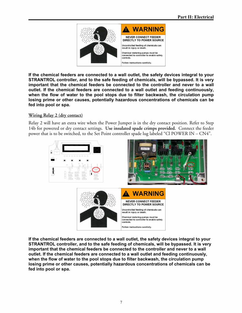
If the chemical feeders are connected to a wall outlet, the safety devices integral to your STRANTROL controller, and to the safe feeding of chemicals, will be bypassed. It is very important that the chemical feeders be connected to the controller and never to a wall outlet. If the chemical feeders are connected to a wall outlet and feeding continuously, when the flow of water to the pool stops due to filter backwash, the circulation pump losing prime or other causes, potentially hazardous concentrations of chemicals can be fed into pool or spa. Wiring Relay 2 (dry contact)
Relay 2 will have an extra wire when the Power Jumper is in the dry contact position. Refer to Step 14b for powered or dry contact settings. Use insulated spade crimps provided. Connect the feeder power that is to be switched, to the Set Point controller spade lug labeled “Cl POWER IN – CN4”.
If the chemical feeders are connected to a wall outlet, the safety devices integral to your STRANTROL controller, and to the safe feeding of chemicals, will be bypassed. It is very important that the chemical feeders be connected to the controller and never to a wall outlet. If the chemical feeders are connected to a wall outlet and feeding continuously, when the flow of water to the pool stops due to filter backwash, the circulation pump losing prime or other causes, potentially hazardous concentrations of chemicals can be fed into pool or spa.

Part II: Electrical
8
Wiring Relay 2 (powered)
Relay 2 controls chlorine. Refer to Step 14a for powered or dry contact settings. The feeder may be wired in two ways. The easiest is to plug the feeder into the female power line running from the hole on the right. You may then go on to Step 16. The second way to wire Relay 2 is to open the cover (as explained in Step 9) and then connect to spade lugs in the base of the unit as follows. Use insulated spade crimps provided. Connect the black (power) wire to the spade lug labeled “Cl Feed – CN8”, connect the green (earth ground) wire to the spade lug labeled “EARTH – CN10”, and connect the white (neutral) wire to the spade lug labeled “NEUTRAL – CN9” (Note: the black and white wires are colored brown and blue outside North America).
Oxidizers (Chlorine or Bromine), acids (Muriatic or Carbon Dioxide) and caustics (Sodium Hydroxide, Caustic Soda, or Soda Ash) are common chemicals used to automatically maintain safe and healthy pool and spa water chemistry. The automatic feeding of these chemicals is performed using sensors, which continuously monitor the water circulating through the filter(s). Each of the sensors is associated with a chemical it is monitoring and feeding. These sensors, their connectors, and the feeder power cords, if present, are color coded. The BLUE sensor is associated with the feed of Chlorine or Bromine (sometimes called an oxidant or oxidizer). If these sensors or chemical feed pumps are not plugged into to the proper connections, or are connected to opposite devices, the uncontrolled feeding of one or both chemicals can occur. Uncontrolled or improper feeding of these two chemicals can cause serious injury or death to swimmers in the pool area from the formation of chlorine gas. Use extreme caution when connecting chemical feeders and sensors.

Part II: Electrical
9
Placing the PowerJumper “CN15”
The power jumper enables you to have “Cl Feed – CN8” at the base of the unit function as a powered or dry (unpowered) contact (some Calcium Hypochlorite feeders require that the power for the relay come from the feeder). Placing the jumper on the left two pins causes the contact to be powered, while placing the jumper on the right two pins causes the contact to be dry. To change the position of the jumper, pull it out and then replace it in the other position.
If the chemical feeders are connected to a wall outlet, the safety devices integral to your Strantrol controller, and to the safe feeding of chemicals, will be bypassed. It is very important that the chemical feeders are connected to the controller and never to a wall outlet. If the chemical feeders are connected to a wall outlet and feeding continuously, when the flow of water to the pool stops due to filter backwash, the circulation pump losing prime or other causes, potentially hazardous concentrations of chemicals can be fed into pool or spa. Wiring Relay 3 Relay 3 is used for Alarms. Use insulated spade crimps provided. Connect the black (power) wire to the spade lug labeled “ALARM – CN11”, connect the green (earth ground) wire to the spade lug labeled “EARTH – CN13”, and connect the white (neutral) wire to the spade lug labeled “NEUTRAL – CN12” (Note: the black and white wires are colored brown and blue outside North America).
Wiring a Flow Switch (Refer to Appendix A)
Part III: DIP Switch and Jumper Settings
10
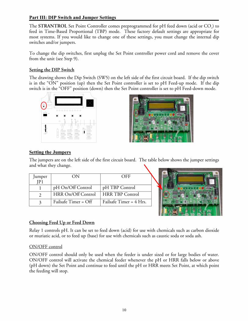
The STRANTROL Set Point Controller comes preprogrammed for pH feed down (acid or CO2) to feed in Time-Based Proportional (TBP) mode. These factory default settings are appropriate for most systems. If you would like to change one of these settings, you must change the internal dip switches and/or jumpers. To change the dip switches, first unplug the Set Point controller power cord and remove the cover from the unit (see Step 9). Setting the DIP Switch
The drawing shows the Dip Switch (SW5) on the left side of the first circuit board. If the dip switch is in the “ON” position (up) then the Set Point controller is set to pH Feed-up mode. If the dip switch is in the “OFF” position (down) then the Set Point controller is set to pH Feed-down mode.
Setting the Jumpers
The jumpers are on the left side of the first circuit board. The table below shows the jumper settings and what they change.
Jumper JP1
ON OFF
1 pH On/Off Control pH TBP Control
2 HRR On/Off Control HRR TBP Control
3 Failsafe Timer = Off Failsafe Timer = 4 Hrs.
Choosing Feed Up or Feed Down
Relay 1 controls pH. It can be set to feed down (acid) for use with chemicals such as carbon dioxide or muriatic acid, or to feed up (base) for use with chemicals such as caustic soda or soda ash. ON/OFF control
ON/OFF control should only be used when the feeder is under sized or for large bodies of water. ON/OFF control will activate the chemical feeder whenever the pH or HRR falls below or above (pH down) the Set Point and continue to feed until the pH or HRR meets Set Point, at which point the feeding will stop.

Part III: DIP Switch and Jumper Settings
11
Timed-Based Proportional control
In Time-Based Proportional (TBP) control the Set Point controller will cycle the feeder ON for a fraction of 30-seconds depending on the amount of deviation from Set Point. The smaller the deviation, the less time the feeder is ON. TBP feature helps to hold a Set Point and to minimize over-shoot by making a standard feeder mimic the action of more sophisticated modulating feeders. TBP has two changeable variables to fit specific applications, span and time base. The span sets the distance from the Set Point that TBP will be in control before the feeder is strictly ON. If overshoots are still experienced increase the span. If the Set Point is taking too long to attain set point, decrease the span. The time base is the total of ON and OFF time. After the time base exceeds the controller will adjust the time ON and OFF to fit the current reading. This time base can be increased to gain longer ON and OFF times. Typically for pools the time base would be set to 60 seconds and for spas 30 seconds. The determining factor for the change of the time base is turnover time of the body of water.\ Example: HRR Feed
HRR Span = 30 mV Time Base = 30 seconds HRR Set Point = 750 mV
HRR Display ON (sec) OFF (sec)
750 mV 0 30
740 mV 10 20
730 mV 20 10
720 mV and below 30 0
Setting the Failsafe Timer Settings
The most common failures of automated chemical feed systems are depletion of the chemical supply and/or chemical feeder failure. Both problems result in the controller being unable to reach Set Point in a reasonable period of time. The failsafe (overfeed) interval sets the maximum length of time the feeder can feed chemical. If the feeder has been trying to achieve Set Point without success for the selected time, the controller will cut power to the feeder, flash the feed light on the face panel and display a message to alert the operator. If unit goes into failsafe alarm, it can be reset by pressing and holding the Up and Down Arrow keys for 2 seconds. Replacing the Cover
Now it is time to put the cover back on the unit. Place the cover back on the unit and tighten the four screws at the corners to secure it in place.


Part IV: Programming
13
Entering the Program Menu
To enter the program menu, press and hold both the Cal and Up key for 3 seconds. When the LCD screen clears, release the keys and "Program" should appear on the display. Press the Up key to enter the menu and press the Down key to exit. Use the Up or Down Arrows to scroll to the setting you wish to change. Press the Cal key to select the setting, then use the Up or Down Arrows to modify the value. Press the Cal key again to enter the new value and return to the menu. To exit the program menu, scroll to the "Exit menu" option and depress the Cal key. NOTE: After two minutes of no programming activity, the Time-Out feature will automatically exit the programming menu.
Strantrol Set Point
Setting the pH High Alarm Point
Pressing the Down Arrow displays pH High followed by the current pH high alarm point. If you would like to change this setting, press the Cal key and then use the Up or Down Arrows to input the value you would like. Then press the Cal key again to enter the new value. Setting the pH Low Alarm Point
Pressing the Down Arrow displays pH Low followed by the current pH low alarm point. If you would like to change this setting, press the Cal key and then use the Up or Down Arrows to input the value you would like. Then press the Cal key again to enter the new value. Setting the HRR High Alarm Point
Pressing the Down Arrow displays HRR High followed by the current HRR high alarm point. If you would like to change this setting, press the Cal key and then use the Up or Down Arrows to input the value you would like. Then press the Cal key again to enter the new value.
pH High 7.8
pH Low 7.2
HRR High 900
Part IV: Programming
14
Setting the HRR Low Alarm Point
Pressing the Down Arrow displays HRR Low followed by the current HRR low alarm point. If you would like to change this setting, press the Cal key and then use the Up or Down Arrows to input the value you would like. Then press the Cal key again to enter the new value.
Exiting the Menu
Pressing the Down Arrow displays Exit menu. Pressing the Cal key exits the programming menu. Displaying Set Point
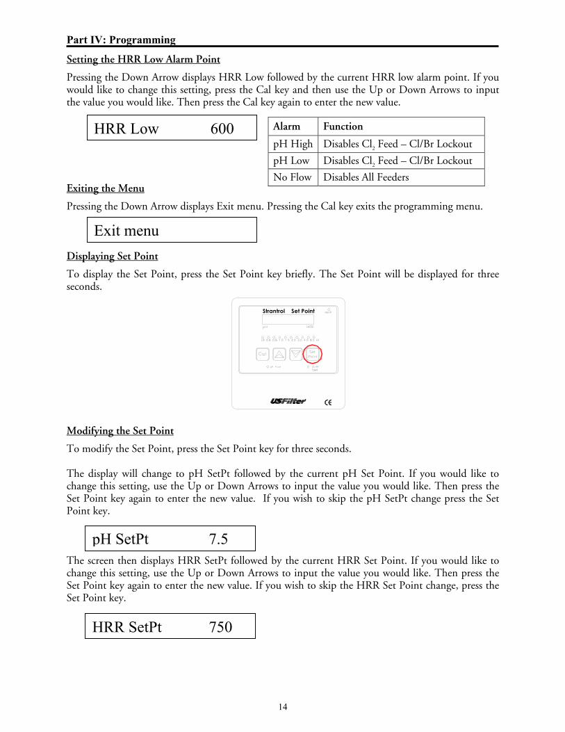
To display the Set Point, press the Set Point key briefly. The Set Point will be displayed for three seconds.
Strantrol Set Point
Modifying the Set Point
To modify the Set Point, press the Set Point key for three seconds. The display will change to pH SetPt followed by the current pH Set Point. If you would like to change this setting, use the Up or Down Arrows to input the value you would like. Then press the Set Point key again to enter the new value. If you wish to skip the pH SetPt change press the Set Point key. The screen then displays HRR SetPt followed by the current HRR Set Point. If you would like to change this setting, use the Up or Down Arrows to input the value you would like. Then press the Set Point key again to enter the new value. If you wish to skip the HRR Set Point change, press the Set Point key.
Alarm Function
pH High Disables Cl2 Feed – Cl/Br Lockout
pH Low Disables Cl2 Feed – Cl/Br Lockout
No Flow Disables All Feeders
HRR Low 600
Exit menu
pH SetPt 7.5
HRR SetPt 750

Part IV: Programming
15
Single Point Calibration
To enter the calibration menu, press and hold the Cal key for three seconds. After the display clears, release the Cal key. The display should now read Cal pH followed by the current pH calibration value.
Strantrol Set Point
Use your test kit to determine the actual pH and then use the arrow keys to adjust the displayed value to the real value and then press the Cal key to enter it.
The display should then read Cal ppm and the ppm LEDs will be flashing.
Once again, use your test kit to determine the actual ppm and then use the arrow keys to adjust this value shown on the LED bar graph to the correct reading and then press the Cal key to enter it. Resetting the Failsafe Alarm
To reset a failsafe alarm press and hold the Up and Down Arrow keys for two seconds.
Strantrol Set Point
Cal pH 7.4
Cal ppm

Part V: Maintenance
17
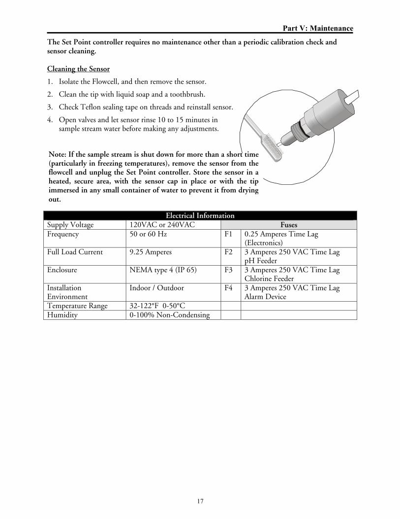
The Set Point controller requires no maintenance other than a periodic calibration check and sensor cleaning. Cleaning the Sensor
1. Isolate the Flowcell, and then remove the sensor.
2. Clean the tip with liquid soap and a toothbrush.
3. Check Teflon sealing tape on threads and reinstall sensor.
4. Open valves and let sensor rinse 10 to 15 minutes in sample stream water before making any adjustments.
Electrical Information Supply Voltage 120VAC or 240VAC Fuses Frequency 50 or 60 Hz F1 0.25 Amperes Time Lag
(Electronics) Full Load Current 9.25 Amperes F2 3 Amperes 250 VAC Time Lag
pH Feeder Enclosure NEMA type 4 (IP 65) F3 3 Amperes 250 VAC Time Lag
Chlorine Feeder Installation Environment
Indoor / Outdoor F4 3 Amperes 250 VAC Time Lag Alarm Device
Temperature Range 32-122°F 0-50°C Humidity 0-100% Non-Condensing
Note: If the sample stream is shut down for more than a short time(particularly in freezing temperatures), remove the sensor from theflowcell and unplug the Set Point controller. Store the sensor in aheated, secure area, with the sensor cap in place or with the tipimmersed in any small container of water to prevent it from dryingout.


Appendix A
i
Sample Stream General Recommendations and Precautions The Strantrol sample flow switch is provided solely for the sample flow “enable” signal to the Strantrol controller. The flow switch provided is for the protection of swimmers when the sample stream flow stops. In this situation, the Strantrol is designed to stop the feed of chemicals and indicate a “No-Flow” Alarm to alert the operator that the sample stream is not flowing and automatic control has been interrupted. Under normal conditions the flow switch, when closed, (in the “sample flow active” position) signals the Strantrol that the sample is flowing and that automatic control can resume.
Stranco recommends, and good facilities design dictates that an additional safety device also be installed. To avoid the formation of gaseous chlorine when concentrated Chlorine and acidic chemicals are combined in a stopped water line, a flow switch must be installed in the water line accepting the chemical injection. The filter circulation return piping is typically the place where this occurs. When this line slows or stops flowing at the normal rate, a flow switch must be installed and wired so that it will then interrupt the feed of chemicals. This safety device should be installed whether or not automated controls are connected to the chemical pumps.
In many cases, the Strantrol supplied sample flow switch is used as the only flow switch for the entire control system. If plumbed and connected properly, this arrangement can perform both tasks safely and reliably. If the water flow slows or stops in the water line where chemicals are being injected, all chemical feed must be prevented. Chemical feed must also be interrupted in the event of the sample stream being interrupted or slowed. It is the responsibility of the installer to assure the safe installation and operation of both the return line and sample stream flow switches.
The recommended installation diagrams on the following pages illustrate how a single flow switch can be plumbed to perform both tasks. If the recommended installation cannot be accomplished due to site specific or application limitations, an additional return line flow switch must be installed to protect the people in the pool area.
Particular care should be taken during equipment installation or replacement, to assure these devices are plumbed, wired and functioning properly. The safety of the swimmers is also dependent upon the regular testing of these devices to assure they are in good working order. A good time to test these devices is whenever a filter backwash or any probe or sample flowcell maintenance is performed.

Appendix A
ii
Installing the Sample Flowcell The flowcell can be mounted using two different techniques:
• Mount the flowcell next to the controller and run 1/2” tubing from the flowcell to the sampling point (after filter, before heater) and discharge (before recirculation pump) of the recirculation system (see diagram).
• Mount the flowcell next to the sampling point (after filter, before heater) of the recirculation system and run wires to the controller using a Signal Transmitter (refer to Signal Transmitter).
Installation with Reed Flow Switch
FLOWCELL INSTALLATION
DATE: 01/26/05 REV. # 3
WARNING: FAILURE TO INCORPORATE A FLOW SWITCH INTO THE SAMPLE STREAM AND A SYSTEM FLOW SWITCH IN YOUR CHEMICAL CONTROL SYSTEM CAN RESULT IN INJURY OR DEATH TO SWIMMERS IN OR AROUND THE POOL, IF THE RECIRCULATION PUMP SHOULD FAIL OR IS SHUT DOWN.
FLOW
RECIRCULATIONPUMP
BACKWASHTO WASTE
IN
OUT
IN
(4-12 lpm)
1/2" P.E. TUBING (12mm)1-3gpm
CAUTION: ANTI-SIPHON DEVICES MUST BE INSTALLED TO INSURE THAT UNCONTROLLED FEED OF CHEMICAL WILL NOT OCCUR IF A VACUUM IS CREATED IN THE RETURN LINE.
HEATER
pH FEED DEVICEINJECTION POINT
Cl/Br FEED DEVICEINJECTION POINT
WARNING: TO AVOID THE CREATION OF HAZARDOUS CHEMICAL CONCENTRATIONS, NEVER COMBINE CHEMICALS INTO A COMMON INJECTION LINE. ALWAYS SEPARATE THE INDIVIDUAL CHEMICAL INJECTION POINTS BY AT LEAST 12 INCHES. CHEMICAL INJECTION POINTS MUST BE DOWNSTREAM FROM ANY HEATERS AND THE LAST ITEMS IN THE RETURN LINE TO THE POOL OR SPA.
WARNING: INSURE SAMPLE STREAM IS INSTALLED TO ASSURE THE FLOW SWITCH AND SYSTEM FLOW SWITCH STOPS WHENEVER WATER IS NOT FLOWING PAST CHEMICAL INJECTION POINTS.THIS MUST INCLUDE FILTER BACKWASH AND LOSS OF PRIME IN THE MAIN WATER RECIRCULATION PUMP. BE SURE TO TEST THAT THE FLOW SWITCH STOPS WITHIN 20 SECONDS AND THE FLOW ALARM ACTIVATES, WHENEVER FLOW IS INTERRUPTED TO THE RETURN LINE. BOTH FLOW SWITCHES MUST BE CHECKED PERIODICALLY (AT LEAST MONTHLY).
OUT
FLOWTO POOL
SYSTEM FLOW SWITCH
SAMPLE STREAMFLOW SWITCH
POSITIVEPRESSURE
SAMPLECELL
Flow switches are provided with allStrantrol controllers and are an integralsafety device to prevent theuncontrolled feed of chemicals, whichcould cause personal injury or death.The flow switch should NEVER bebypassed, even temporarily, as thiscritical safety device will not beavailable to protect the swimmers.

Appendix A
iii
Installation with Reed Flow Switch
FLOWCELL INSTALLATION
DATE: 01/26/05 REV. # 3
WARNING: FAILURE TO INCORPORATE A FLOW SWITCH INTO THE SAMPLE STREAM AND A SYSTEM FLOW SWITCH IN YOUR CHEMICAL CONTROL SYSTEM CAN RESULT IN INJURY OR DEATH TO SWIMMERS IN OR AROUND THE POOL, IF THE RECIRCULATION PUMP SHOULD FAIL OR IS SHUT DOWN.
(4-12 lpm)
1/2" P.E. TUBING (12mm)1-3gpm
SAMPLE CELL
POSITIVE PRESSURE
CAUTION: ANTI-SIPHON DEVICES MUST BE INSTALLED TO INSURE THAT UNCONTROLLED FEED OF CHEMICAL WILL NOT OCCUR IF A VACUUM IS CREATED IN THE RETURN LINE.
pH FEED DEVICEINJECTION POINT
Cl/Br FEED DEVICEINJECTION POINT
WARNING: TO AVOID THE CREATION OF HAZARDOUS CHEMICAL CONCENTRATIONS, NEVER COMBINE CHEMICALS INTO A COMMON INJECTION LINE. ALWAYS SEPARATE THE INDIVIDUAL CHEMICAL INJECTION POINTS BY AT LEAST 12 INCHES. CHEMICAL INJECTION POINTS MUST BE DOWNSTREAM FROM ANY HEATERS AND THE LAST ITEMS IN THE RETURN LINE TO THE POOL OR SPA.
WARNING: INSURE SAMPLE STREAM IS INSTALLED TO ASSURE THE FLOW SWITCH AND SYSTEM FLOW SWITCH STOPS WHENEVER WATER IS NOT FLOWING PAST CHEMICAL INJECTION POINTS.THIS MUST INCLUDE FILTER BACKWASH AND LOSS OF PRIME IN THE MAIN WATER RECIRCULATION PUMP. BE SURE TO TEST THAT THE FLOW SWITCH STOPS WITHIN 20 SECONDS AND THE FLOW ALARM ACTIVATES, WHENEVER FLOW IS INTERRUPTED TO THE RETURN LINE. BOTH FLOW SWITCHES MUST BE CHECKED PERIODICALLY (AT LEAST MONTHLY).
FLOWTO POOL
SYSTEM FLOW SWITCH
HEATER
FILTER
FLOW
VACUUM
FLOW
RECIRCULATIONPUMP
SAMPLE STREAMFLOW SWITCH
Plumbing the Flowcell
• Half-inch tubing is recommended for sample stream pickup and return. We have included two connector fittings with the flowcell if needed.
• For the sampling point of the flowcell, tap downstream of (after) filter and upstream of heater (unheated sample) and prior to chemical injection points. (See drawing above) Installation of a valve is recommended at this point for maintenance and sample line isolation.
• For the discharge point of the flowcell, tap upstream of (before) recirculation pump. (See drawing above)
• Remove the cap to the pH and HRR sensors, clean tips with a toothbrush and dish soap and then a dilute acid.
• Screw pH, HRR and Temperature sensors into flowcell. (See drawing below)
If a vacuum is created in the watercirculation line and no anti-siphondevice is installed on the chemicalfeeders, potentially hazardousconcentrations of chemicals can bedrawn into the pool or spa. Alwaysuse injection check valves and anti-siphon valves in the chemical feedlines to prevent this situation fromoccurring.

Appendix A
iv
Sensor placement with a Reed Flow Switch
HRR SENSORpH SENSOR
TEMPERATURESENSOR
Appendix A
v
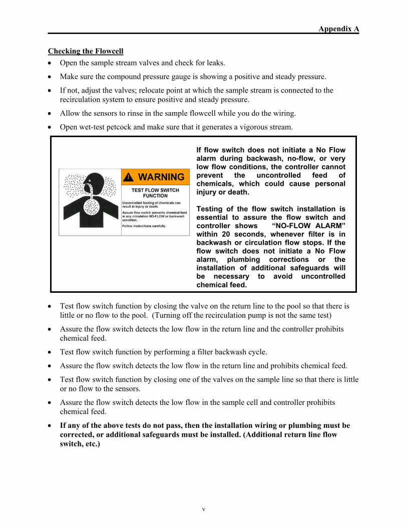
Checking the Flowcell • Open the sample stream valves and check for leaks.
• Make sure the compound pressure gauge is showing a positive and steady pressure.
• If not, adjust the valves; relocate point at which the sample stream is connected to the recirculation system to ensure positive and steady pressure.
• Allow the sensors to rinse in the sample flowcell while you do the wiring.
• Open wet-test petcock and make sure that it generates a vigorous stream.
• Test flow switch function by closing the valve on the return line to the pool so that there is
little or no flow to the pool. (Turning off the recirculation pump is not the same test)
• Assure the flow switch detects the low flow in the return line and the controller prohibits chemical feed.
• Test flow switch function by performing a filter backwash cycle.
• Assure the flow switch detects the low flow in the return line and prohibits chemical feed.
• Test flow switch function by closing one of the valves on the sample line so that there is little or no flow to the sensors.
• Assure the flow switch detects the low flow in the sample cell and controller prohibits chemical feed.
• If any of the above tests do not pass, then the installation wiring or plumbing must be corrected, or additional safeguards must be installed. (Additional return line flow switch, etc.)
If flow switch does not initiate a No Flowalarm during backwash, no-flow, or verylow flow conditions, the controller cannotprevent the uncontrolled feed ofchemicals, which could cause personalinjury or death. Testing of the flow switch installation isessential to assure the flow switch andcontroller shows “NO-FLOW ALARM”within 20 seconds, whenever filter is inbackwash or circulation flow stops. If theflow switch does not initiate a No Flowalarm, plumbing corrections or theinstallation of additional safeguards willbe necessary to avoid uncontrolledchemical feed.
Appendix A
vi
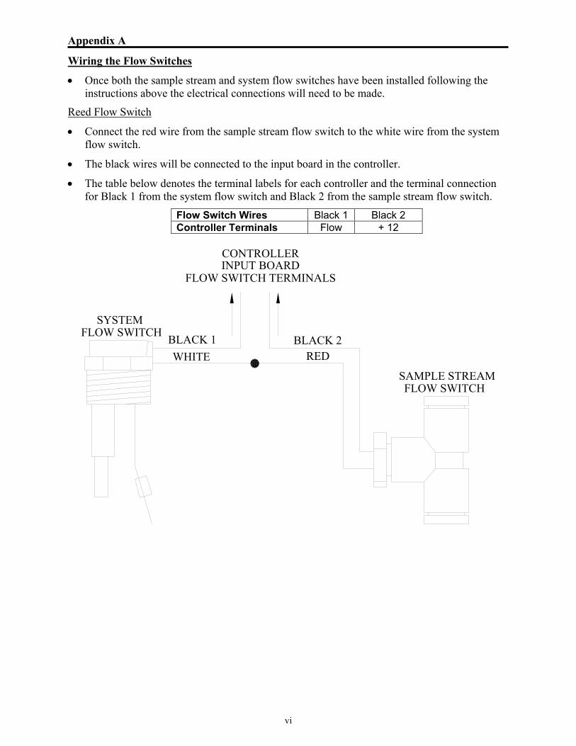
Wiring the Flow Switches
• Once both the sample stream and system flow switches have been installed following the instructions above the electrical connections will need to be made.
Reed Flow Switch
• Connect the red wire from the sample stream flow switch to the white wire from the system flow switch.
• The black wires will be connected to the input board in the controller.
• The table below denotes the terminal labels for each controller and the terminal connection for Black 1 from the system flow switch and Black 2 from the sample stream flow switch.
WHITEBLACK 2
REDBLACK 1
SYSTEMFLOW SWITCH
FLOW SWITCHSAMPLE STREAM
INPUT BOARDCONTROLLER
FLOW SWITCH TERMINALS
Flow Switch Wires Black 1 Black 2 Controller Terminals Flow + 12

Appendix B
i
Use the charts on the following pages to determine the correct amount of chemical to add to spa or pool water to achieve desired conditions. Choose which chart to use by the chemical indicated and the number of gallons to be treated.

Appendix B
ii


STRANTROL® SET POINT
Installation, Operations & Maintenance Manual
SALES/SERVICE
1.866.766.5987 Fax: 815.932.1760
www.strancoaquatics.com
E-mail: [email protected]
To find out more about how to put
USFilter to work for you, contact us at
Stranco Products Level 1, 6-10 Talavera Road Priory Works, Tonbridge P.O. Box 389 North Ryde, NSW 2113 Kent, TN11 0QL Bradley, IL 60915 U.S.A. Australia United Kingdom 815.932.8154 phone +61.(2)9850.2822 phone +44.(0)1732.354888 phone 815.932.1760 fax +61.(2)9850.2898 fax +44.(0)1732.354222 fax For more information, call 866.766.5987 or
visit our web site at
www.strancoaquatics.com
© 2005 USFilter Corporation
USFilter Corporation reserves the right to change the specifications referred to in this literature at any time without prior notice. Strantrol is a trademark of United States Filter Corporation and/or its affiliates. Teflon is a trademark of DuPont. ST-Set Point-MAN-0305