Embed Size (px)
DESCRIPTION
Strain wave gearing application notes
Citation preview

Page 1
Ordering Information
Design Guidelines
Assembly Tolerances
Minimum Casing Clearance
Flexspline Mounting
Assembly Sequence
Lubrication
Minimum Oil Volume
Application Notes & Handbook
T h r e e B a s i c C o m p o n e n t s
* Flexspline
* Circular Spline
* Wave Generator
K e y A d v a n t a g e s
* Low or Zero Backlash
* High Efficiencies
* Simple Support Requirements
* High Single-Stage Rations
* High Torque Output
* Excellent Positional Accurancy
and Repeatability
* Design Flexibility
* Long Life and High Reliability
B r i e f L i s t o f A p p l i c a t i o n s * Aerospace
* Industrial Robots
* Medical Equipment
* Machine Tools
* Measuring and Testing
Machines
* Printing Presses
* Semi-Conductor Equipment
Manufacturing
* Communiations Equipment
* Terminology
* Woodworking Machine
Engineering Data Common
Ordering Information
HDC - 80 - 100 - 2 - 6 / 6 - (SP)*1
*1 --- SP (Special order with custom design)*2 --- Transmission Error | --- Grade 6: ± 180 arc sec for industrial grade | --- Grade 3: ± 90 arc sec for robotics grade | --- Grade 1: ± 30 arc sec for robotics grade*3 --- Backlash | --- Grade 6: 6 (±3) arc min for industrial grade | --- Grade 3: 3 (±1.5) arc min for robotics grade | --- Grade 1: 1 (±0.5) arc min for robotics grade
||||||
|||||
||||
|||
||
| --- Transmission error: Grade 6 (*2)--- Backlash: Grade 6 (*3)
--- 2 - Three Basic Components 1 - Gearbox--- Transmission ratio 100:1
--- Size 80--- Model HDC (Cup Type Components)
SWG Solutions

Page 2
Strain Wave Gearing
Design Guidelines
Cup Style Components Design Sample:
The relative perpendicularity and concentricity of the three basic Strain Wave Gearing components have an important influence on accuracy and service life. Pay attention on the following points:
1) Input shaft, Circular spline and housing must be concentric.2) Oil input and assembly check.3) Air vent depending on the application.4) A clamping ring with corner radius increases torque transmission capacity and prevents damage to Flexspline diaphragm.5) The Flexspline pilot diameter must be concentric to Circular Spline.6) Pre-loaded and backlash-free double bearing support for output shaft.7) A radial shaft seal for oil lubrication.8) Axial location of Flexspline.9) Flexspline and Circular Spline must be located in parallel and perpendicular to the Output Shaft.10) Oil drain11) Double bearing support for Input Shaft.
T h r e e B a s i c C o m p o n e n t s
* Flexspline
* Circular Spline
* Wave Generator
K e y A d v a n t a g e s
* Low or Zero Backlash
* High Efficiencies
* Simple Support Requirements
* High Single-Stage Rations
* High Torque Output
* Excellent Positional Accurancy
and Repeatability
* Design Flexibility
* Long Life and High Reliability
B r i e f L i s t o f A p p l i c a t i o n s * Aerospace
* Industrial Robots
* Medical Equipment
* Machine Tools
* Measuring and Testing
Machines
* Printing Presses
* Semi-Conductor Equipment
Manufacturing
* Communiations Equipment
* Terminology
* Woodworking Machine
SWG Solutions

Page 3
Strain Wave Gearing
Pancake Style Components Design Sample:
T h r e e B a s i c C o m p o n e n t s
* Flexspline
* Circular Spline
* Wave Generator
K e y A d v a n t a g e s
* Low or Zero Backlash
* High Efficiencies
* Simple Support Requirements
* High Single-Stage Rations
* High Torque Output
* Excellent Positional Accurancy
and Repeatability
* Design Flexibility
* Long Life and High Reliability
B r i e f L i s t o f A p p l i c a t i o n s * Aerospace
* Industrial Robots
* Medical Equipment
* Machine Tools
* Measuring and Testing
Machines
* Printing Presses
* Semi-Conductor Equipment
Manufacturing
* Communiations Equipment
* Terminology
* Woodworking Machine
SWG Solutions

Page 4
Strain Wave Gearing
T h r e e B a s i c C o m p o n e n t s
* Flexspline
* Circular Spline
* Wave Generator
K e y A d v a n t a g e s
* Low or Zero Backlash
* High Efficiencies
* Simple Support Requirements
* High Single-Stage Rations
* High Torque Output
* Excellent Positional Accurancy
and Repeatability
* Design Flexibility
* Long Life and High Reliability
B r i e f L i s t o f A p p l i c a t i o n s * Aerospace
* Industrial Robots
* Medical Equipment
* Machine Tools
* Measuring and Testing
Machines
* Printing Presses
* Semi-Conductor Equipment
Manufacturing
* Communiations Equipment
* Terminology
* Woodworking Machine
Assembly Tolerances
Cup Style Components Assembly Tolerances:
For Industrial Grade Strain Wave Gearing
Dimensions: (mm)
Size a b c d e f g50 0.020 0.025 0.020 0.025 0.020 0.020 0.01560 0.020 0.025 0.020 0.025 0.020 0.025 0.01580 0.025 0.030 0.025 0.030 0.025 0.025 0.020
100 0.025 0.030 0.025 0.030 0.025 0.030 0.020120 0.030 0.030 0.025 0.035 0.025 0.035 0.020
SWG Solutions

Page 5
Strain Wave Gearing
T h r e e B a s i c C o m p o n e n t s
* Flexspline
* Circular Spline
* Wave Generator
K e y A d v a n t a g e s
* Low or Zero Backlash
* High Efficiencies
* Simple Support Requirements
* High Single-Stage Rations
* High Torque Output
* Excellent Positional Accurancy
and Repeatability
* Design Flexibility
* Long Life and High Reliability
B r i e f L i s t o f A p p l i c a t i o n s * Aerospace
* Industrial Robots
* Medical Equipment
* Machine Tools
* Measuring and Testing
Machines
* Printing Presses
* Semi-Conductor Equipment
Manufacturing
* Communiations Equipment
* Terminology
* Woodworking Machine
For Robotics Grade Strain Wave GearingDimensions: (mm)
Size a b c d e f g50 0.010 0.015 0.012 0.015 0.012 0.012 0.01060 0.010 0.015 0.012 0.015 0.012 0.015 0.01080 0.012 0.020 0.015 0.020 0.012 0.015 0.012
100 0.012 0.025 0.015 0.020 0.012 0.020 0.012120 0.015 0.025 0.015 0.025 0.015 0.020 0.012
Pancake Style Components Assembly Tolerances:
Size a b c d e f g50 0.020 0.020 0.020 0.025 0.020 0.020 0.01560 0.020 0.025 0.020 0.025 0.020 0.025 0.01580 0.025 0.025 0.025 0.030 0.025 0.025 0.020
100 0.025 0.030 0.025 0.030 0.025 0.030 0.020120 0.030 0.035 0.025 0.035 0.025 0.035 0.020
For Industrial Grade Strain Wave Gearing
Dimensions: (mm)
SWG Solutions

Page 6
Strain Wave Gearing
T h r e e B a s i c C o m p o n e n t s
* Flexspline
* Circular Spline
* Wave Generator
K e y A d v a n t a g e s
* Low or Zero Backlash
* High Efficiencies
* Simple Support Requirements
* High Single-Stage Rations
* High Torque Output
* Excellent Positional Accurancy
and Repeatability
* Design Flexibility
* Long Life and High Reliability
B r i e f L i s t o f A p p l i c a t i o n s * Aerospace
* Industrial Robots
* Medical Equipment
* Machine Tools
* Measuring and Testing
Machines
* Printing Presses
* Semi-Conductor Equipment
Manufacturing
* Communiations Equipment
* Terminology
* Woodworking Machine
Minimum Casing Clearance
In order to allow deflective motion of the Flexspline, a certain amount of clearance must be provided between the inner walls of the casing and the Flexspline, as illustrated. In the case of oil lubrication, larger clearances are recommended to provide a sufficient amount of lubricant.
Size a b c d e f g50 0.010 0.012 0.012 0.015 0.012 0.020 0.01560 0.010 0.015 0.012 0.015 0.012 0.025 0.01580 0.012 0.015 0.015 0.020 0.012 0.025 0.020
100 0.012 0.020 0.015 0.020 0.012 0.030 0.020120 0.015 0.020 0.015 0.025 0.015 0.035 0.020
For Robotics Grade Strain Wave Gearing
Dimensions: (mm)
Dimensions: (mm)
Size 50 60 80 100 120Øa (diameter) Ø54 Ø66 Ø84 Ø104 Ø130
b 2 2 3 3 4
SWG Solutions

Page 7
Strain Wave Gearing
T h r e e B a s i c C o m p o n e n t s
* Flexspline
* Circular Spline
* Wave Generator
K e y A d v a n t a g e s
* Low or Zero Backlash
* High Efficiencies
* Simple Support Requirements
* High Single-Stage Rations
* High Torque Output
* Excellent Positional Accurancy
and Repeatability
* Design Flexibility
* Long Life and High Reliability
B r i e f L i s t o f A p p l i c a t i o n s * Aerospace
* Industrial Robots
* Medical Equipment
* Machine Tools
* Measuring and Testing
Machines
* Printing Presses
* Semi-Conductor Equipment
Manufacturing
* Communiations Equipment
* Terminology
* Woodworking Machine
Flexspline Mounting
A clamp ring must be used as part of the assembly to attach the Flexspline to the out-put shaft. The outside diameter of the clamp ring must be less than the diameter of the Flexspline’s mounting boss. The outer diameter of the contact surface must have a radius to protect the Flexspline diaphragm from damage.
SWG Solutions

Page 8
Strain Wave Gearing
T h r e e B a s i c C o m p o n e n t s
* Flexspline
* Circular Spline
* Wave Generator
K e y A d v a n t a g e s
* Low or Zero Backlash
* High Efficiencies
* Simple Support Requirements
* High Single-Stage Rations
* High Torque Output
* Excellent Positional Accurancy
and Repeatability
* Design Flexibility
* Long Life and High Reliability
B r i e f L i s t o f A p p l i c a t i o n s * Aerospace
* Industrial Robots
* Medical Equipment
* Machine Tools
* Measuring and Testing
Machines
* Printing Presses
* Semi-Conductor Equipment
Manufacturing
* Communiations Equipment
* Terminology
* Woodworking Machine
Care must be taken that the heads of clamping bolts, nuts, washers, or clamp rings are kept within the diameter of the Flexspline hub, otherwise local flexing of the Flexspline will be hampered and eventual failure will result. The corner of the clamp ring must be rounded to allow local flexing.
Dimensions: (mm)
Size 50 60 80 100 120ØD (Max. clamp ring diameter) Ø32 Ø40 Ø52 Ø64 Ø80
R (Corner radius) 1 1 1.5 1.5 2
The Flexspline is rotationally connected to an output shaft by clamping bolts. The total clamping force required are shown below.
Dimensions: (mm)
Size 50 60 80 100 120No. of bolts 6 6 6 6 6Size of bolts M4 M5 M6 M8 M12
Clamp torque/bolt (N.m) 4.2 8.5 14.5 35.5 80
Assembly Sequence
SWG Solutions
Page 9
Strain Wave Gearing
T h r e e B a s i c C o m p o n e n t s
* Flexspline
* Circular Spline
* Wave Generator
K e y A d v a n t a g e s
* Low or Zero Backlash
* High Efficiencies
* Simple Support Requirements
* High Single-Stage Rations
* High Torque Output
* Excellent Positional Accurancy
and Repeatability
* Design Flexibility
* Long Life and High Reliability
B r i e f L i s t o f A p p l i c a t i o n s * Aerospace
* Industrial Robots
* Medical Equipment
* Machine Tools
* Measuring and Testing
Machines
* Printing Presses
* Semi-Conductor Equipment
Manufacturing
* Communiations Equipment
* Terminology
* Woodworking Machine
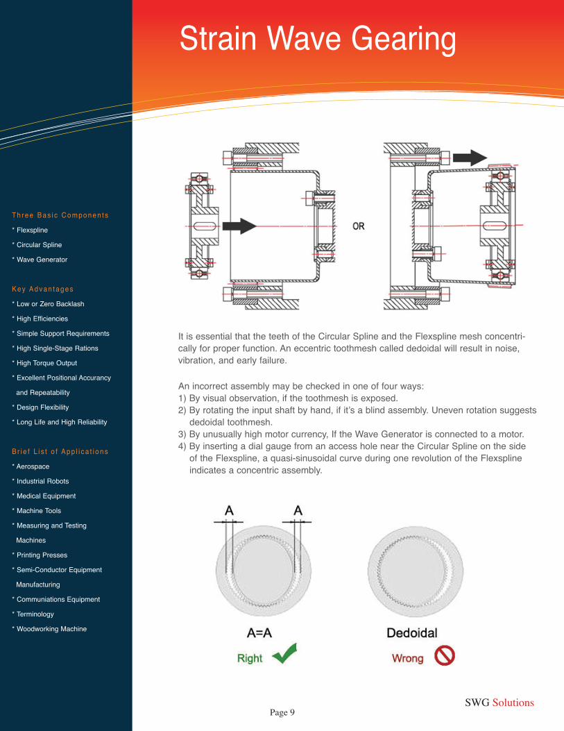
It is essential that the teeth of the Circular Spline and the Flexspline mesh concentri-cally for proper function. An eccentric toothmesh called dedoidal will result in noise, vibration, and early failure.
An incorrect assembly may be checked in one of four ways:1) By visual observation, if the toothmesh is exposed.2) By rotating the input shaft by hand, if it’s a blind assembly. Uneven rotation suggests dedoidal toothmesh.3) By unusually high motor currency, If the Wave Generator is connected to a motor.4) By inserting a dial gauge from an access hole near the Circular Spline on the side of the Flexspline, a quasi-sinusoidal curve during one revolution of the Flexspline indicates a concentric assembly.
SWG Solutions

Page 10
Strain Wave Gearing
T h r e e B a s i c C o m p o n e n t s
* Flexspline
* Circular Spline
* Wave Generator
K e y A d v a n t a g e s
* Low or Zero Backlash
* High Efficiencies
* Simple Support Requirements
* High Single-Stage Rations
* High Torque Output
* Excellent Positional Accurancy
and Repeatability
* Design Flexibility
* Long Life and High Reliability
B r i e f L i s t o f A p p l i c a t i o n s * Aerospace
* Industrial Robots
* Medical Equipment
* Machine Tools
* Measuring and Testing
Machines
* Printing Presses
* Semi-Conductor Equipment
Manufacturing
* Communiations Equipment
* Terminology
* Woodworking Machine
Oil ChangeThe first oil change should be performed after 100 hours of operation. The need to per-form subsequent oil changes will depend on operating conditions, but should take place at intervals of approximately 1000 running hours.
Grease ChangeWhen operating at rated torque, change grease after about 1000 running hours. Light-duty operation may permit longer service intervals. To change grease, Completely disassemble and clean units before regreasing. Apply grease generously inside the Flexspline, the Wave Generator bearing, the input coupling, and the teeth of the Circular Spline and the Flexspline.
Oil TemperatureThe Max. permissible temperature rise is 60°C, as oil loses its lubricating capability quickly above this limit.
Service Instructions1) Semi-fluid grease is used for SWG-C-25 to SWG-C-60. They were pre-lubricated with the grease prior to packaging in the factory.2) For SWG-C-80 to SWG-C-120, oil lubrication is used. ( If input speed is less than 2000rpm, grease lubrication may be used as well, but the requirement must be declared when ordering).3) All oil-lubricated reducers are delivered with dry case. Before operating, users have to fill in suitable oil themselves. For this purpose, a plug and an air-vent are provided on the top of the case. the oil used must be clean and free from impurities. Oil level needed is indicated by the middle-line in the oil indicator, i.e. to keep the oil surface 2 mm higher than the center of the ball lowest in position in the flexible ball bearing.4) The air-vent must always be on the vertical up position.
Lubrication
SizeAmblent temperature
0 ~ +55 -40 ~ +55 -50 ~ +10025
HDG-LO (Strain Wave Gearing semifluid grease #0)32405060 80 32 HDL
(HD. Lube)32HDL.L
(Low temp. HD Lube)
4109 (Synthetic oil) 100
120
SWG Solutions

Page 11
Strain Wave Gearing
T h r e e B a s i c C o m p o n e n t s
* Flexspline
* Circular Spline
* Wave Generator
K e y A d v a n t a g e s
* Low or Zero Backlash
* High Efficiencies
* Simple Support Requirements
* High Single-Stage Rations
* High Torque Output
* Excellent Positional Accurancy
and Repeatability
* Design Flexibility
* Long Life and High Reliability
B r i e f L i s t o f A p p l i c a t i o n s * Aerospace
* Industrial Robots
* Medical Equipment
* Machine Tools
* Measuring and Testing
Machines
* Printing Presses
* Semi-Conductor Equipment
Manufacturing
* Communiations Equipment
* Terminology
* Woodworking Machine
Vertical Installations
In vertical installations with the input shaft down, the oil level is set at the centerline of the Wave Generator bearing balls.If the input shaft is on top, a “lift cone” should be provided. This serves to pump oil onto the Wave generator, tooth mesh region, and coupling. For the lift cone to be effective, a minimum input speed of 960 rpm must be maintained, as lower speeds do not gener-ate enough liftforce. For lower input speeds, either fill oil up to the middle of the Wave Generator bearing or use grease lubrication. Note that lube holes are provided on the boss of the Flexspline to facilitate the flow of oil inside the Flexspline cup. The lube holes serve as breathers if the component set is used with input down.When the Strain Wave Gearing unit is to be used vertically with the Wave Generator placed at the bottom, special consideration must be given. If the Wave Generator assembly is completely submerged in oil, the heat generation caused by churning would be substantial and a loss of efficiency would result. It is recommended that the oil level be maintained in such a way that approximately one half of the Wave Generator bearing is submerged.To assure a sufficient amount of lubricant it may be necessary to extend the bottom area of the housing or to provide an external oil reservoir. A forced lubrication system may also be considered.
Minimum Oil Volume
Dimensions: (mm)
Size
HorizontalA (mm)
Vertical with WG up Vertical with WG downC (mm)B1 (mm) B (mm)
50 2 20 26 260 2 22 29 280 4 28 37 4100 4 35 47 4120 6 45 59 6
SWG Solutions

Page 12
Strain Wave Gearing
T h r e e B a s i c C o m p o n e n t s
* Flexspline
* Circular Spline
* Wave Generator
K e y A d v a n t a g e s
* Low or Zero Backlash
* High Efficiencies
* Simple Support Requirements
* High Single-Stage Rations
* High Torque Output
* Excellent Positional Accurancy
and Repeatability
* Design Flexibility
* Long Life and High Reliability
B r i e f L i s t o f A p p l i c a t i o n s * Aerospace
* Industrial Robots
* Medical Equipment
* Machine Tools
* Measuring and Testing
Machines
* Printing Presses
* Semi-Conductor Equipment
Manufacturing
* Communiations Equipment
* Terminology
* Woodworking Machine
For retention of grease within the tooth mesh areaand the ball bearing, it is recom-mended that the housing at least S dimension.
HDF Grease lubricated ratings
Dimensions: (mm)
Size 25 32 40 50 60 80 100 120ØS (diameter) Ø24 Ø31 Ø39 Ø47 Ø57 Ø75 Ø95 Ø115

Page 13
Strain Wave Gearing
T h r e e B a s i c C o m p o n e n t s
* Flexspline
* Circular Spline
* Wave Generator
K e y A d v a n t a g e s
* Low or Zero Backlash
* High Efficiencies
* Simple Support Requirements
* High Single-Stage Rations
* High Torque Output
* Excellent Positional Accurancy
and Repeatability
* Design Flexibility
* Long Life and High Reliability
B r i e f L i s t o f A p p l i c a t i o n s * Aerospace
* Industrial Robots
* Medical Equipment
* Machine Tools
* Measuring and Testing
Machines
* Printing Presses
* Semi-Conductor Equipment
Manufacturing
* Communiations Equipment
* Terminology
* Woodworking Machine
Transmission error is defined as the difference between the output shaft’s actual posi-tion and its theoretical output position. This is measured in a unidirectional rotation.
The alllowable values are: Grade 6 / Grade 3 / Grade 1
Grade 6 : ± 180 arc sec for industrial gradeGrade 3 : ± 90 arc sec for robotics gradeGrade 1 : ± 30 arc sec for robotics grade
Transmission Error
Lost Motion is defined as the lag of the output shaft’s rotational angle when the input shafts position is altered, under no-load conditions.
The alllowable values are: Grade 6 / Grade 3 / Grade 1
Grade 6 : 6 (±3) arc min for industrial gradeGrade 3 : 3 (±1.5) arc min for robotics gradeGrade 1 : 1 (±0.5) arc min for robotics grade
Backlash (Lost Motion)
No-Load Static Starting Torque
Size Starting Torque (g-cm) 25 30 ~ 80 32 45 ~ 16040 60 ~ 200 50 80 ~ 30060 120 ~ 50080 200 ~ 800100 400 ~ 1250120 650 ~ 1800

Page 14
89 Fawndale Cres.Toronto, ON, M1W 2X3 CanadaPhone 647-294-8847Web: www.swgearing.comEmail: [email protected]
About SWG SolutionsWe are specialized in Strain Wave Gearing products. Our advanced manufacturing capabilities provide high quality and preci-sion for your requirements.
Our customers represent the electronics, automotive, industrial, medical and food industries. We offer our customers high quality products with exceptional customer services.
We believe in satisfying our customers and respond quickly to their needs with prompt, effective and global solutions. With us you will deal with a highly specialized and professional experts.
SWG Solutions provide standard Strain Wave Gearing components and gearheads, and also provide custom design Strain Wave Gearing systems.
T h r e e B a s i c C o m p o n e n t s
* Flexspline
* Circular Spline
* Wave Generator
K e y A d v a n t a g e s
* Low or Zero Backlash
* High Efficiencies
* Simple Support Requirements
* High Single-Stage Rations
* High Torque Output
* Excellent Positional Accurancy
and Repeatability
* Design Flexibility
* Long Life and High Reliability
B r i e f L i s t o f A p p l i c a t i o n s * Aerospace
* Industrial Robots
* Medical Equipment
* Machine Tools
* Measuring and Testing
Machines
* Printing Presses
* Semi-Conductor Equipment
Manufacturing
* Communiations Equipment
* Terminology
* Woodworking Machine
Strain Wave Gearing
![Electromechanical wave imaging and electromechanical wave … · 2019-07-23 · motion and strain estimation based on Bmode [9] or radio-frequency (RF) ultrasound signals [10–13]](https://img.dokumen.tips/doc/110x75/5e9f95fa3886094c5e322e3d/electromechanical-wave-imaging-and-electromechanical-wave-2019-07-23-motion-and.jpg)


![[47] Strain wave gearing design system wave gearing...167 AMTEC [47] Strain wave gearing design system Fig.47.1 Strain wave gearing design system 47.1 Overview Strain wave gearing](https://img.dokumen.tips/doc/110x75/5e356487029e073cbd586fdc/47-strain-wave-gearing-design-wave-gearing-167-amtec-47-strain-wave-gearing.jpg)