Embed Size (px)
Citation preview

STR550Indicator - Indicatore
User manual - Manuale installatore


Summary1 Safety guide lines ...................................................................................................................62 Model identification ..............................................................................................................63 Technical Data ........................................................................................................................7 3.1 General data ..............................................................................................................74 Hardware data ........................................................................................................................7 4.1 Software data ............................................................................................................85 Dimensions and Installation ...............................................................................................96 Electrical wirings ................................................................................................................. 10 6.1 Wiring diagram ...................................................................................................... 107 Display and Key Functions .................................................................................................14 7.1 Keys .............................................................................................................................14 7.2 Display .......................................................................................................................158 Controller Functions ........................................................................................................... 16 8.1 Memory Card (optional) ...................................................................................... 16 8.2 Modifying alarm thresholds ................................................................................17 8.3 Latch on function....................................................................................................17 8.4 Digital input functions ..........................................................................................19 8.5 Peak values ...............................................................................................................19 8.6 Totalizer function ................................................................................................... 20 8.7 Sum function........................................................................................................... 20 8.8 Customizable linear input ................................................................................... 219 Alarm Intervention Modes ................................................................................................ 2110 Serial communication ....................................................................................................... 2311 Configuration ....................................................................................................................... 27 11.1 Modifying configuration parameters .............................................................. 27 11.2 Loading default values ......................................................................................... 2712 Table of configuration parameters ................................................................................ 28 12.1 Analogue input ...................................................................................................... 28 12.2 V/I custom ................................................................................................................ 32

12.3 Alarm 1 ..................................................................................................................... 36 12.4 Alarm 2 ..................................................................................................................... 39 12.5 Display ...................................................................................................................... 41 12.6 Digital input 1 ......................................................................................................... 42 12.7 Digital input 2 ......................................................................................................... 43 12.8 Graphic ..................................................................................................................... 44 12.9 Analogue output in mA ........................................................................................ 45 12.10 Analogue output in Volt ....................................................................................... 46 12.11 Comunication port ................................................................................................ 47
Sommario1 Norme di sicurezza ............................................................................................................. 492 Identificazione del modello .............................................................................................. 493 Dati tecnici ............................................................................................................................ 50 3.1 Caratteristiche generali ....................................................................................... 504 Caratteristiche hardware .................................................................................................. 50 4.1 Caratteristiche software ...................................................................................... 515 Dimensione e installazione .............................................................................................. 526 Collegamenti elettrici......................................................................................................... 53 6.1 Schema di collegamento ..................................................................................... 537 Funzione dei visualizzatori e tasti ................................................................................... 57 7.1 Tasti ........................................................................................................................... 57 7.2 Display ...................................................................................................................... 588 Funzioni del regolatore ..................................................................................................... 59 8.1 Memory Card (opzionale) .................................................................................... 59 8.2 Modifica soglie di allarme ................................................................................... 60 8.3 Funzione Latch on ................................................................................................. 60 8.4 Funzioni da Ingresso digitale.............................................................................. 62 8.5 Valori di picco .......................................................................................................... 62 8.6 Funzione totalizzatore. ........................................................................................ 63

8.7 Funzione somma ................................................................................................... 63 8.8 Linearizzazione personalizzata......................................................................... 64 8.9 Modi d’intervento allarmi ................................................................................... 64 8.10 Data logger ............................................................................................................. 669 Comunicazione Seriale ...................................................................................................... 6710 Configurazione .................................................................................................................... 72 10.1 Modifica parametro di configurazione ........................................................... 72 10.2 Caricamento valori di default ............................................................................ 7211 Tabella parametri di configurazione ............................................................................. 73 11.1 Ingresso analogico ................................................................................................ 73 11.2 V/I personalizzato .................................................................................................. 77 11.3 Allarme 1 .................................................................................................................. 81 11.4 Allarme 2 .................................................................................................................. 84 11.5 Display ...................................................................................................................... 86 11.6 Ingresso digitale 1 .................................................................................................. 87 11.7 Ingresso digitale 2 .................................................................................................. 88 11.8 Grafico ...................................................................................................................... 89 11.9 Uscita analogica in mA ........................................................................................ 90 11.10 Uscita analogica in Volt ....................................................................................... 91 11.11 Comunicazione seriale ......................................................................................... 92

6 STR550 - User manual
IntroductionThanks for choosing a device.STR550 is an indicator/panel meter for acquisition and retransmission of processes, also with fast transient. It is provided with relay outputs for alarm purpose, analogue outputs for retransmission of process/setpoints and programmable digital inputs.Available in standard format 96x48mm, the device can be configured both for horizontal and vertical mounting.Distinctive feature is the intuitive multilingual interface, supported by a graphic LCD display 128x64pixel with backlighting programmable for 7 colors. Visualization options include bargraph and process trend with programmable sampling time. Software features include mathematical functions related to process value like Totalizer and Sum.Serial connectivity relies on RS485 and Modbus-RTU protocol.
1 Safety guide linesRead carefully the safety guidelines and programming instructions contained inthis manual before using/connecting the device. Disconnect power supply before proceeding to hardware settings or electrical wirings.Only qualified personnel should be allowed to use the device and/or service it and in accordance to technical data and environmental conditions listed in this manual. Do not dispose electric tools together with household waste material. In observance European Directive 2002/96/EC on waste electrical and electronicequipment and its implementation in accordance with national law, electric toolsthat have reached the end of their life must be collected separately and returnedto an environmentally compatible recycling facility.
2 Model identificationModel 24..230 Vac/Vdc +/-15% 50/60 Hz – 6 VASTR550-12ABC-T 2 Relays 2 A + 1V + 1mA + 2D.I. + RS485

User manual - STR550 7
3 Technical Data
3.1 General dataDisplay Backlighting graphic LCD 2.7”Operatingtemperature
Temperature 0-45 °C Humidity 35..95 uR%
SealingIP54 front panel (with gasket)IP20 box and terminals
Material Box: Polycarbonate V0Weight Approx. 165 g
4 Hardware data
Power supplyExtended power supply 24..230 Vac/Vdc ±15% 50/60 Hz
Consumption: 6 VA.
Analogue input
1: AN1 Configurable via software. Thermocouple type K, S, R, J, T, E, N, B. Automatic compensation of cold junction from 0..50 °C.Thermoresistance: PT100, PT500, PT1000, Ni100, PTC1K, NTC10K (β 3435K).Input V/I (linear): 0-10 V, 0-20, 4-20 mA, 0-60 mV.Potentiometer input: 6 KΩ, 150 KΩ.
Tolerance (25 °C)+/-0.2% ±1 digit (F.s.) for thermocouple, thermoresi-stance and V / mA.Cold junction accuracy 0.1 °C/°C.
Impedance:0-10 V: Ri>110 KΩ0-20 mA: Ri<5 Ω4-20 mA: Ri<5 Ω0-60 mV: Ri>1 MΩ
Relay outputs 2 Relays Contacts 2 A - 250 V~.Resistive charge.

8 STR550 - User manual
Analogue output
1 tensionLinear 0..10 Volt.1 current Configurable as output 0..20mA or 4..20mA.
All 16bit +/-0.2% (F.s.)
4.1 Software dataRegulationalgorithms
ON/OFF with hysteresis
Alarm modeAbsolute / Threshold, Band with instantaneous/delayed/retentive action/by digital input activation, Sensor failure / Activation by serial line
Sum FunctionBy digital input or by keyboard it is possible to sum different process measurements over time
Totalizer FunctionVisualisation of instant process value and total value since last reset
Trend visualization
Trend visualisation with selectable time basis 1 to 3600s
Analogue retransmission
Process values / Setpoints
Digital transmission
Process values / Setpoint / Parameters via RS485
Latch-on functionSemi-automatic setting of limits/ calibration values for analogue input
Data logging function
Selectable time basis 1s to 3600s, tot. memory 2,5K Word
Text menus English/Italian/Deutsch/French/Spanish

User manual - STR550 9
5 Dimensions and Installation

10 STR550 - User manual
6 Electrical wirings Although this controller has been designed to resist noises in an industrial environment, please notice the following safety guidelines:• Separate control lines from the power wires.
• Avoid the proximity of remote control switches, electromagnetic meters,powerful engines.• Avoid the proximity of power groups, especially those with phase control.
6.1 Wiring diagram
+-
T C
1812
1711
1610
159
148
137
R S 485
P T CN T C
P T 100-N I100
V /I+-
+-
0V
A O 10/4. . . 20m A
+-
+-
A O 20. . . 10V
S U P P LY24. . . 230VA C /D C6
5
4
3
2
1
Q 12A 2 30VR e s is tiv e1/8H P
Q 22A 2 30VR e s is tiv e1/8H P
+24V dc
D I . 1
D I . 2
Power supply5
SUPPLY24..230VAC/DC
6
Switching supply with extended range 24…230 Vac/dc ±15% 50/60Hz – 6VA (galvanic isolated)

User manual - STR550 11
AN1 analogue imput
13
AI1 TC
14
For thermocouples K, S, R, J, T, E, N, B. • Comply with polarity.• For possible extensions, use a compensated wire
and terminals suitable for the thermocouples used (compensated).
• When shielded cable is used, it should be grounded at one side only.
13AI1
14
PT/N
i100
Shield/Schermo
White/Bianco
Red/Rosso
Red/Rosso 15
For thermoresistances PT100, NI100.• For the three-wire connection use wires with the same
section.• For the two-wire connection short-circuit terminals 14 and
15.• When shielded cable is used, it should be grounded at one
side only.13
14Red/Rosso
White/Bianco
Red/Rosso 15
14AI1
15
PTC/
NTC
Shield/Schermo For thermoresistances NTC, PTC, PT500, PT1000 andlinear potentiometers.When shielded cable is used, it should be grounded atone side only to avoid ground loop currents.
13V/I
+24Vdc14
10
Shield/Schermo
For linear signals V / mA.• Comply with polarity.• When shielded cable is used, it should be grounded at one side only.

12 STR550 - User manual
Example of connection for linear input Volt and mAPRESSURE TRANSMITTER /SENSORE DI PRESSIONE
P :0
...10
0mba
rP
max
:3ba
rT
:0..7
0°C
OU
T : 4
...20
mA
IN
:9.
..33V
DC
14
13
10B
C
A
4..20mA
For linear signals 0/4..20 mA with three-wire sensor.Comply with polarity:A= Sensor outputB= Sensor groundC= Sensor power supply (+24Vdc / 35mA)
External supply /A l imentaz ione esterna
P :0
...10
0mba
rP
max
:3ba
rT
:0..7
0°C
OU
T : 4
...20
mA
IN
:9.
..33V
DC
PRESSURE TRANSMITTER /SENSORE DI PRESSIONE
1413
A
B
4...20mAFor linear signals 0/4..20 mA with external power of sensor.Comply with polarity:A= Sensor outputB= Sensor ground
P :0
...10
0mba
rP
max
:3ba
rT
:0..7
0°C
OU
T : 4
...20
mA
IN
:9.
..33V
DC
10
14
C
A
PRESSURE TRANSMITTER /SENSORE DI PRESSIONE
4..20mAFor linear signals 0/4..20 mA with two-wire sensor.Comply with polarity:A= Sensor outputC= Sensor power supply (+24Vdc / 35mA)
Serial input
16RS485
17
18
Shield/Schermo
RS485 Modbus RTU communication

User manual - STR550 13
Relay Q1 output3
Q12A230V1/8Hp
4
Capacity:2 A / 250 V~ for resistive loads.NB: see picture below
Relay Q2 output1
Q22A230V1/8Hp
2
Capacity:2A/250 V~ for resistive loads.NB: see picture below
Electrical endurance Q1 / Q2.2 A, 250 Vac, resistive load, 105 operations.20/2 A, 250 Vac, cosφ = 0.3, 105 operations.
mA / Volt output7
AO10/4..20mA
8
Pins 7-8: linear output in mA configurable using parameters as retransmission of process or alarm setpoints (see par. 112-116).
8AO20..10V
9
Pins 8-9: linear output in Volt configurable using parameters as retransmission of process or alarm setpoints (vedi par. 119-123).

14 STR550 - User manual
Digital Input 1
10
11
+24VdcDI1(PnP)
PNP digital inputDigital input according to parameter 95
Short-circuit pins 10 and 11 to activate the digital input 1
Digital input 2
10
12
+24Vdc
DI2(PnP)
PNP digital inputDigital input according to parameter 100
Short-circuit pins 10 and 12 to activate the digital input 2
7 Display and Key Functions
7.1 Keys
Keys are multifunction: in correspondence of each key its meaning is displayed.If no description is showed, press a key to visualize it.

User manual - STR550 15
7.2 DisplayIt visualizes the process, the setpoints and all configuration parameters. The programming/ operation interface with text menus in 5 languages makes the navigation intuitive.
This page displays the process, the relays status and the serial communication (if available).
This page displays the process, the relays status and a graph representing the process trend.
This page displays the process and its graphic representation as bargraph.

16 STR550 - User manual
8 Controller Functions
8.1 Memory Card (optional)Parameters and setpoint values can be duplicated from one controller to another using the Memory card.2 modes are available:• With the controller connected to the power supply::Insert memory card when the controller is off. On activation the LCD visualizes
Load data and Esc in correspondence of the relative keys (only if the correct values are saved in the memory card). Pressing Load data the controller loads the new values. Pressing Esc the device keeps the old values.• With the controller not connected to the power supply:The memory card is equipped with an internal battery with an autonomy of about 1000 uses (2032 button battery, replaceable).Insert the memory card and press the programming button. When writing the parameters, led turns red and on completing the procedure it changes to green. It is possible to repeat the procedure without any particular attention.NB: it is not possible to transfer the parameters of a device to one with different code: the LED lights red.
Updating Memory Card.To update the memory card values, follow the procedure described on first mode, pressing Esc so as not to load the parameters on controller.
Enter configuration and change at least one parameter. Exit configuration. Changes are stored automatically.
User manual - STR550 17
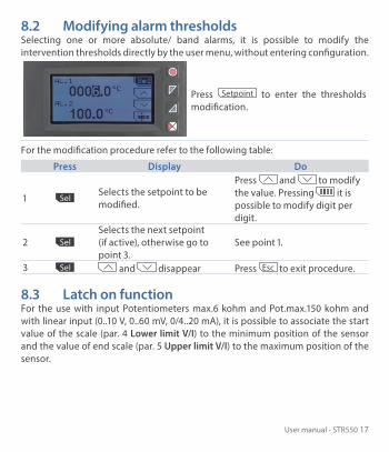
8.2 Modifying alarm thresholdsSelecting one or more absolute/ band alarms, it is possible to modify the intervention thresholds directly by the user menu, without entering configuration.
Press Setpoint to enter the thresholds modification.
For the modification procedure refer to the following table:
Press Display Do
1 Sel Selects the setpoint to be modified.
Press and to modify the value. Pressing it is possible to modify digit per digit.
2 Sel Selects the next setpoint (if active), otherwise go to point 3.
See point 1.
3 Sel and disappear Press Esc to exit procedure.
8.3 Latch on functionFor the use with input Potentiometers max.6 kohm and Pot.max.150 kohm and with linear input (0..10 V, 0..60 mV, 0/4..20 mA), it is possible to associate the start value of the scale (par. 4 Lower limit V/I) to the minimum position of the sensor and the value of end scale (par. 5 Upper limit V/I) to the maximum position of the sensor.

18 STR550 - User manual
To use the LATCH ON function: enter confi guration, select Setting on par. 8 Latch on and press Sel (STR550 shows the page in the picture).
For the calibration procedure refer to the following table:
Press Display Do
1Place the sensor on minimum operating value (associated with Lower limit V/I).
2 Set the value on minimum.Place the sensor on maximum operating value (associated with Upper limit V/I).
3 Set the value to maximum.
To exit standard procedurepress Esc .For zero settings place the sensor on the zero point
4 0 Set the virtual zero value. Press Esc to exit procedure.
MaxMin Zero

User manual - STR550 19
8.4 Digital input functionsOn the STR550 model, digital inputs can be enabled by configuring the par. 95 Digital input 1 and the par. 100 Digital Input 2.
• Run: allows the action of relays and linear output.• Hold: locks the conversion.• Tare zero (AI): selects to zero the process value (tare function).• Alarm reset: if one or more alarms are selected with manual reset and alarm
conditions are no longer present, closing the digital input it is possible to restore the alarm output.
• Totalizer reset: if the totalizer function is active, using the digital input it is possible to reset the counter.
• Peaks reset: min. peak/max. peak/peak-to-peak values are reset. • Sum total: if the sum function is active, using the digital input it is possible to
increase the “sum” counter as indicated by the process value. • Sum reset: if the sum function is active, using the digital input it is possible to
reset the “sum” counter.• Config. lock: if the digital input is active it is not possible to enter configuration
or to modify the setpoints.
Selecting Digital input 1 or Digital input 2 on the alarm parameters, the related relays will activate togheter with the digital input; functions selected on parameters 95 and 100 will continue to work.
8.5 Peak valuesThe STR550 is provided with a page for the visualization of peak values: max. peak, min. peak and peak-to-peak of analogue input. Keeping pressed Rst it is possible to reset the visualized values.

20 STR550 - User manual
8.6 Totalizer functionThe totalizer function, which can be enable by par. 9 Totalizer, performs an instant measurement of the process and sums it on a time basis to the previously totalized value.
On the dedicated page it is possible to see the instant process value and the totalized value: keeping pressed Rst it is possible to reset this value.
Ex.: if a sensor 4..20mA with F.s. 9000m3/hour is connected, it is necessary to select Hour on par. 9 Totalizer. The device will increase the totalized value considering the m3 flowing each second (2.5m3).
8.7 Sum functionThe sum function, which can be enabled by par. 10 Sum function, allows to increase a counter adding the process value on command. It is an application typical for weighing systems and allows to know the total weighed value.
Press Sum Function to enter the function page. Pressing + the Process value is added to the counter. It is possible to reset the total value keeping pressed Rst and to fix “tare zero” of the process pressing Tar .
Functions tare, sum and reset can be managed also by digital input if enabled on par. 95 Digital Input 1 and par. 100 Digital Input 2.

User manual - STR550 21
8.8 Customizable linear inputSelecting 16 steps on par. 17 V/I custom and connecting a linear sensor it is possible to customize the linear input for a max. of 16 steps. On parameters xx-Input value it is necessary to enter the value of the input to which the value selected on the corresponding parameter xx-Custom value will be related.Example: sensor 0-10V.01-Input value => 0.000V 01-Custom value=>0mBar02-Input value => 2.000V 02-Custom value=>100mBar03-Input value => 5.000V 03-Custom value=>500mBar04-Input value => 10.000V 04-Custom value=>1000mBar
At each value in volt (input) it is related a value in mBar (customized): if the sensor supplies 2V the device visualizes 100mBar, if it supplies 5V the device visualizes 500mBar. For intermediate tension values the value in mBar is calculated linearly between the entered values containing it: 1V = 50mBar, 3.5V=300mBar and 7V=700mBar.
9 Alarm Intervention Modes
Absolute alarm (absolute selection)
1
Alarm Spv
Pv
O�On On
O�
Hysteresispar. > 0
Time
Alarmoutput
Absolute alarm and hysteresis value greater than “0” (Par. 58 hysteresis > 0).N.B. The example refers to alarm 1; the function can also be enabled for alarms 2

22 STR550 - User manual
2
Alarm Spv
Pv
O�On On
O�
Hysteresispar. < 0
Time
Alarmoutput
Absolute alarm and hysteresis value less than “0” (Par. 58 hysteresis < 0).N.B. The example refers to alarm 1; the function can also be enabled for alarms 2.
Band alarm (band selection)
1
Alarm Spv
Pv
Dev. Spv
Dev. Spv
O� O� O�On On On
Hysteresispar. > 0
Time
Alarmoutput
Dev. Spv
Dev. Spv
Band alarm and hysteresis value greater than “0” (Par. 58 hysteresis > 0).N.B. The example refers to alarm 1; the function can also be enabled for alarms 2.
2
Pv
Dev. Spv
O� O� O�On On On
Hysteresispar. < 0
Hysteresispar. < 0
Time
Alarmoutput
Dev. SpvAlarm Spv
Band alarm and hysteresis value less than “0” (Par. 58 hysteresis < 0).N.B. The example refers to alarm 1; the function can also be enabled for alarms 2.

User manual - STR550 23
Digital input alarm (selection “Digital input 1” or “Digital input 2”)Alarm related to digital input: the relay activates with digital input active.
Loop Break Alarm (selection“L.B.A.”)Sensor alarm breakage: the relay activates in case of sensor breakage or sensor out of range.
Remote control alarm (selection “remote Ctrl ”)The relay activates writing 1 on word modbus 1015 for the alarm 1 and on word modbus 1016 for the alarm 2. Writing 0 the relay deactivates.
10 Serial communicationSTR550-12ABC-T equipped with RS485 can receive and broadcast data via serial communication using MODBUS RTU protocol. The device can be configured only as a Slave. This function enables the control of multiple controllers connected to a supervisory system. Each controller responds to a master query only if the query contains the same address as that in the parameter par. 126 Slave address.The permitted addresses range from 1 to 254 and there must not be controllers with the same address on the same line.Address 255 can be used by the master to communicate with all the connected equipment (broadcast mode), while with 0 all the devices receive the command, but no response is expected. STR550 can introduce a delay (in milliseconds) in the response to the master request. This delay must be set on parameter 129 Serial Delay.Each parameter change is saved by the controller on EEPROM memory (100000 writing cycles).

24 STR550 - User manual
NB: changes made to Words that are different from those reported in the followingtable can lead to malfunction.
Modbus RTU protocol features
Baud-rate
Selection on par. 127 Baud Rate:1.200 baud 28.800 baud2.400 baud 38.400 baud4.800 baud 57.600 baud9.600 baud 115.200 baud19.200 baud
Format
Selection on par. 128 Serial format:8, N, 1 (8 bit, no parity, 1 stop)8, E, 1 (8 bit, even parity, 1 stop)8, O, 1 (8 bit, odd parity, 1 stop)8, N, 2 (8 bit, no parity, 2 stop)8, E, 2(8 bit, even parity, 2 stop)8, O, 2 (8 bit, odd parity, 2 stop)
Supportedfunctions
WORD READING (max 20 word) (0x03, 0x04)SINGLE WORD WRITING (0x06)MULTIPLE WORDS WRITING (max 20 word) (0x10)
Looking at the table here below it is possible to find all available addresses andfunctions:
RO Read Only R/W Read / Write WO Write Only
ModbusAddress Description Read
OnlyReset value
0 Device type RO EEPROM1 Software version RO EEPROM5 Slave address R/W EEPROM6 Boot version RO EEPROM
1000Process (degrees.tenths for temperature sensors; digit for linear sensors)
RO 0

User manual - STR550 25
ModbusAddress Description Read
OnlyReset value
1001Min. peak (degrees.tenths for temperature sensors; digit for linear sensors)
RO 0
1002Max. peak (degrees.tenths for temperature sensors; digit for linear sensors)
RO 0
1003Peak-to-peak (degrees.tenths for temperature sensors; digit for linear sensorsati)
RO 0
1004 Totalizer value (H) RO EEPROM1005 Totalizer value (L) RO EEPROM1006 Sum value (H) RO EEPROM1007 Sum value (L) RO EEPROM1008 Cold junction temperature (degrees.tenths) RO EEPROM
1009Relays status (0 = Off, 1 = On):Bit 0 = Relay Q1Bit 1 = Relay Q2
RO 0
1010Digital inputs status (0 = Off, 1 = Active):Bit 0 = D.I.1Bit 1 = D.I.2
RO -
1011
Keys status (0 = released, 1 = pressed):Bit 0 = Bit 1 = Bit 2 = Bit 3 =
RO 0
1012
Error flagsBit 0 = Cold junction errorBit 1 = Process error (sensor)Bit 2 = Eeprom writing errorBit 3 = Eeprom reading errorBit 4 = Missing calibration data errorBit 5 = Generic errorBit 6 = Hardware error
RO 0

26 STR550 - User manual
ModbusAddress Description Read
OnlyReset value
1013Alarms status (0 = None, 1 = Active)Bit 0 = Alarm 1Bit 1 = Alarm 2
RO 0
1014
Manual reset: write 0 to reset all alarms. In reading (0 = Not resettable, 1 = Resettable)Bit 0 = Alarm 1Bit 1 = Alarm 2
R/W 0
1015 Alarm 1 status (remote control) R/W 01016 Alarm 2 status (remote control) R/W 01017 mA analogue output value (remote control) R/W 01018 Volt analogue output value (remote control) R/W 0
1019Run by serial0 = Inhibited outputs1 = Active outputs
R/W 1
1020Hold by serial0 = Active analogue input1 = Analogue input in Hold
R/W 0
1021 Tare zero AI (write 1) R/W 01022 Totalizer reset (write 1) R/W 01023 Peaks reset (write 1) R/W 01024 Sum total (write 1) R/W 01025 “Total sum” reset (write 1) R/W 02001 Parameter 1 R/W EEPROM2002 Parameter 2 R/W EEPROM2150 Parameter 150 R/W EEPROM4001 Parameter 1* R/W EEPROM4002 Parameter 2* R/W EEPROM4150 Parameter 150* R/W EEPROM
* Parameters modified using serial address 4001 to 4150, will be stored on eeprom only after 10s since last writing of one parameter.

User manual - STR550 27
11 Configuration
11.1 Modifying configuration parametersFor configuration parameters see par. 11
Press Display Do
1 ConfigurationShows 0000 with the 1st digit selected.
2 and Changes the selected digitand moves to the next oneusing .
Enter password 1234
3Sel
to confirmShows the names of the parameter groups.
4 and Scroll up / down theparameter groups.
5
Sel to enter the parameter
group
Shows the parameters of the selected group.
Press and to select parameter to be modified.
6
Sel to enter
the parameter
modification
Shows all parameter possible selections or the parameter numeric value.
Press and to modify parameter. For numeric parameters, pressing it is possible to modify digit-to-digit. Press Sel to confirm modification. Press to exit without modify.
11.2 Loading default valuesEnter password 9999 to restore factory settings of the device.

28 STR550 - User manual
12 Table of configuration parametersThe following table includes all parameters. Some of them will not be visible onthe models which are not provided with relevant Hardware data.
12.1 Analogue inputParameters to configure the analogue input.
1 Sensor type Analogue input configuration/sensor selectionThermocouple K (Default) -260 °C..1360 °CThermocouple S -40 °C..1760 °CThermocouple R -40 °C..1760 °CThermocouple J -200 °C..1200 °CThermocouple T -260 °C..400 °CThermocouple E -260 °C..1000 °CThermocouple N -260 °C..1280 °CThermocouple B +80 °C..1820 °CPt100 -200 °C..600 °CNi100 -60 °C..180 °CNTC 10kOhm -40 °C..125 °CPTC 1kOhm -50 °C..150 °CPt500 -100 °C..600 °CPt1000 -100 °C..600 °C0..10 V0..20 mA4..20 mA0..60 mVPot. max. 6 kOhmPot. max. 150 kOhm

User manual - STR550 29
2 Decimal PointSelects type of the visualized decimal point0 No decimals. Default0.0 1 Decimal0.00 2 Decimals0.000 3 Decimals
3 Measure unitSelects the visualized measure unit°C (Default)°FKVmVAmABarmBarpsiPamm
cmdmmkmingkgqtozlbm/s
m/mm/hl/sl/ml/hm3/sm3/mm3/hrpm%rhph
4 Lower limit V/IRange AN1 lower limit only for linear input. Ex: with input 4..20 mA this para-meter takes value associated to 4 mA-32767 + 32767 [digit1], Default: 0.
5 Upper limit V/I Range AN1 upper limit only for linear input. Ex: with input 4..20 mA thisparameter takes value associated to 20 mA-32767 + 32767 [digit1], Default: 1000.

30 STR550 - User manual
6 Offset calibrationValue added / subtracted to the process visualization (usually correcting thevalue of environmental temperature)-1000..+1000 [digit1] for linear sensors and potentiometers.-100.0..+100.0 (degrees.tenths for temperature sensors). Default 0.0.
7 Gain calibrationPercentage value that is multiplied for the process value (allows to calibratedthe working point)-100.0%..+100.0%, Default: 0.0ex: to correct the range from 0..1000°C showing 0..1010°C, set the parameter to -1.0.
8 Latch OnAutomatic setting of limits for linear inputs and potentiometers Disabled (Default)EnabledSetting
9 TotalizerVisualizes the total “fluid” volume considering the sensor signal as unit/time value (ex. if the connected sensor has an output 4..20mA with F.s. 2000m³/hour, the parameter 9 Totalizer has to be selected as “Hour” and the display will visualize the total fluid volume from the last RESET/START signal). Disabled Display visualizes the process (Default)Second Display visualizes the flow in unit/sMinute Display visualizes the flow in unit/minHour Display visualizes the flow in unit/hour
10 Sum functionEnables the sum function and its dedicated page. Allows to sum the process value to a variable .Disabled (Default)Enabled

User manual - STR550 31
11 StoreEnables to store in eeprom the values of peak, totalizer, sum function and tare zero. If disabled, at starting the above-mentioned values start from 0. The storing is done automatically every 5 minutes. Disabled (Default)Enabled
12 Filter samplesADC Filter: number of input sensor readings to calculate the mean that defines process value. NB: when readings increase, control loop speed slows down.1..15 means Default: 10.
13 Sampling frequencySampling frequency of analogue / digital converter.NB: Increasing the conversion speed will slow down reading stability (ex: forfast transients, as pressure, it is advisable to increase sampling frequency)242 Hz 4.2ms (Maximum speed conversion)123 Hz 8.2ms62 Hz 16.1ms50 Hz 20ms39 Hz 25.6ms33.2 Hz 30.1ms19.6 Hz 51ms16.7 Hz (Default) 59.9ms Ideal for filtering noises 50 / 60 Hz12.5 Hz 80ms10 Hz 100ms8.33 Hz 120ms6.25 Hz 160ms4.17 Hz 240ms (Minimum speed conversion)

32 STR550 - User manual
12.2 V/I customParameters to configure the customizable linear input.
17 V/I customSelects the linearization type for the analogue input if selected as linear.Lower and upper limits. The input will be linearized by parameters 4
and 5 (Default)16 spezzate The input will be linearized by parameter 18-49
18 01-Input valueDefines the input value to which the 1st customized value is assigned0..20000 Default: 0.
19 01-Custom valueDefines the 1st customized value assigned to the input-32767..32767 [Digit1] Default: 0.
20 02-Input valueDefines the input value to which the 2nd customized value is assigned0..20000 Default: 2000.
21 02-Custom valueDefines the 2nd customized value assigned to the input-32767..32767 [Digit1] Default: 1000.
22 03-Input valueDefines the input value to which the 3rd customized value is assigned0..20000 Default: 0.
23 03-Custom valueDefines the 3rd customized value assigned to the input-32767..32767 [Digit1] Default: 0.

User manual - STR550 33
24 04-Input valueDefines the input value to which the 4th customized value is assigned
0..20000 Default: 0.
25 04-Custom valueDefines the 4th customized value assigned to the input-32767..32767 [Digit1] Default: 0.
26 05-Input valueDefines the input value to which the 5th customized value is assigned0..20000 Default: 0.
27 05-Custom valueDefines the 5th customized value assigned to the input-32767..32767 [Digit1] Default: 0.
28 06-Input valueDefines the input value to which the 6th customized value is assigned0..20000 Default: 0.
29 06-Custom valueDefines the 6th customized value assigned to the input-32767..32767 [Digit1] Default: 0.
30 07-Input valueDefines the input value to which the 7th customized value is assigned0..20000 Default: 0.
31 07-Custom valueDefines the 7th customized value assigned to the input-32767..32767 [Digit1] Default: 0.

34 STR550 - User manual
32 08-Input valueDefines the input value to which the 8th customized value is assigned0..20000 Default: 0.
33 08-Custom valueDefines the 8th customized value assigned to the input-32767..32767 [Digit1] Default: 0.
34 09-Input valueDefines the input value to which the 9th customized value is assigned0..20000 Default: 0.
35 09-Custom valueDefines the 9th customized value assigned to the input-32767..32767 [Digit1] Default: 0.
36 10-Input valueDefines the input value to which the 10th customized value is assigned0..20000 Default: 0.
37 10-Custom valueDefines the 10th customized value assigned to the input-32767..32767 [Digit1] Default: 0.
38 11-Input valueDefines the input value to which the 11th customized value is assigned0..20000 Default: 0.
39 11-Custom valueDefines the 11th customized value assigned to the input-32767..32767 [Digit1] Default: 0.

User manual - STR550 35
40 12-Input valueDefines the input value to which the 12th customized value is assigned0..20000 Default: 0.
41 12-Custom valueDefines the 12th customized value assigned to the input-32767..32767 [Digit1] Default: 0.
42 13-Input valueDefines the input value to which the 13th customized value is assigned0..20000 Default: 0.
43 13-Custom valueDefines the 13th customized value assigned to the input-32767..32767 [Digit1] Default: 0.
44 14-Input valueDefines the input value to which the 14th customized value is assigned0..20000 Default: 0.
45 14-Custom valueDefines the 14th customized value assigned to the input-32767..32767 [Digit1] Default: 0.
46 15-Input valueDefines the input value to which the 15th customized value is assigned0..20000 Default: 0.
47 15-Custom valueDefines the 15th customized value assigned to the input-32767..32767 [Digit1] Default: 0.

36 STR550 - User manual
48 16-Input valueDefines the input value to which the 16th customized value is assigned0..20000 Default: 0.
49 16-Custom valueDefines the 16th customized value assigned to the input-32767..32767 [Digit1] Default: 0.
12.3 Alarm 1Parameters to configure the Alarm 1
54 Alarm typeAlarm 1 selectionDisabled (Default)Absolute alarmBand alarmDigital input 1Digital input 2L.B.A.Remote control
55 Contact typeSelects the alarm 1 output contact and intervention typeNormally open (Default)Normally closedN.O. - C.B.A.N.C. - C.B.A.
56 Alarm thresholdSelects the alarm 1 setpoint-32767..+32767 [Digit1] (degrees.tenths for temperature sensors), Default: 0.0.

User manual - STR550 37
57 Deviation thresholdSelects the deviation from alarm 1 setpoint for the band alarm0..+32767 [Digit1] (degrees.tenths for temperature sensors), Default: 0.0.
58 HysteresisAlarm 1 hysteresis-1000..+1000 [Digit1] (degrees.tenths for temperature sensors), Default: 0.0.
59 Reset typeAlarm 1 contact reset typeAutomatic (Default)Manual Manual reset by keyboardManual stored Keeps relay status also after an eventual power failure
60 Error contactState of contact for alarm 1 output in case of errorOpen (Default)Closed
61 Alarm displayDefines the backlighting color during alarm 1None (Default)RedGreenYellowBlueVioletAzureWhite

38 STR550 - User manual
62 Actuation delayAlarm 1 delay.-3600..+3600 seconds. Default: 0Negative: delay in alarm output phase.Positive: delay in alarm entry phase.
63 Lower limitLower limit for alarm 1 setpoint. -32767..+32767 [Digit1] (degrees.tenths for temperature sensors). Default: 0.
64 Upper limitUpper limit for alarm 1 setpoint-32767..+32767 [Digit1] (degrees.tenths for temperature sensors). Default: 1000.
65 ProtectionAlarm 1 set protection. Does not allow user to modify setpointFree Modification allowed (Default)Lock ProtectedHide Protected and not visualized

User manual - STR550 39
12.4 Alarm 2Parameters to configure the Alarm 2
69 Alarm typeAlarm 2 selectionDisabled (Default)Absolute alarmBand alarmDigital input 1Digital input 2L.B.A.Remote control
70 Contact typeSelects the alarm 2 output contact and intervention typeNormally open (Default)Normally closedN.O. - C.B.A.N.C. - C.B.A.
71 Alarm thresholdSelects the alarm 2 setpoint-32767..+32767 [Digit1] (degrees.tenths for temperature sensors), Default: 0.0.
72 Deviation thresholdSelects the deviation from alarm 2 setpoint for the band alarm0..+32767 [Digit1] (degrees.tenths for temperature sensors), Default: 0.0.
73 HysteresisAlarm 2 hysteresis-1000..+1000 [Digit1] (degrees.tenths for temperature sensors), Default: 0.0.

40 STR550 - User manual
74 Reset typeAlarm 2 contact reset typeAutomatic (Default)Manual Manual reset by keyboardManual stored Keeps relay status also after an eventual power failure
75 Error contactState of contact for alarm 2 output in case of errorOpen (Default)Closed
76 Alarm displayDefines the backlighting color during alarm 2None (Default)RedGreenYellowBlueVioletAzureWhite
77 Actuation delayAlarm 2 delay.-3600..+3600 seconds. Default: 0Negative: delay in alarm output phase.Positive: delay in alarm entry phase.
78 Lower limitLower limit for alarm 2 setpoint. -32767..+32767 [Digit1] (degrees.tenths for temperature sensors). Default: 0.

User manual - STR550 41
79 Upper limitUpper limit for alarm 2 setpoint-32767..+32767 [Digit1] (degrees.tenths for temperature sensors). Default: 1000.
80 ProtectionAlarm 2 set protection. Does not allow user to modify setpointFree Modification allowed (Default)Lock ProtectedHide Protected and not visualized
12.5 Display
84 LanguageSelects the languageEnglish (Default)ItalianoDeutschFrançaisEspañol
85 ColorSelects the backlighting colorWhite (Default)AzureVioletBlueYellowGreenRed

42 STR550 - User manual
86 ContrastSelects the contrast value for the LCD0%..100%, Default: 35%.
87 ReverseEnables the LCD reverse visualizationDisabled (Default)Enabled
88 Screen timeoutSelects the LCD backlighting durationAlways on (Default)15 seconds30 seconds1 minute
2 minutes5 minutes10 minutes
30 minutes1 hour
89 Display directionSelects the LCD visualization direction. Horizontal (Default)Vertical
90 Starting pageSelects the page visualized at starting after the initial splash screenProcess (Default)GraphicPeak valuesTotalizerSum function
12.6 Digital input 1Parameters to configure the digital input 1.

User manual - STR550 43
95 Digital input functionSelects the digital input 1 functionDisabled (Default)RunHoldTare zero (AI) (impulse functioning)Alarm resetTotalizer reset (impulse functioning)Peaks resetSum total (impulse functioning)Sum reset (impulse functioning)Config. lock
96 Contact typeSelects the digital input 1 inactive contact. Normally open (Default) Executes function with closed contactNormally closed Executes function with open contact
12.7 Digital input 2Parameters to configure the digital input 2.
100 Input functionSelects the digital input 2 functionDisabled (Default)RunHoldTare zero (AI) (impulse functioning)Alarm resetTotalizer reset (impulse functioning)Peaks resetSum total (impulse functioning)Sum reset (impulse functioning)Config. lock

44 STR550 - User manual
101 Contact typeSelects the digital input 2 inactive contact.Normally open (Default) Executes function with closed contactNormally closed Executes function with open contact
12.8 GraphicParameters to configure the trend and bar graph management.
105 Graphic typeSelects the type of graph to be visualized on the relevant page.Trend (Default)Bar graph
106 Lower limitTrend or bar graph lower limit. -32767 + 32767 [Digit1], Default: 0.
107 Upper limitTrend or bar graph upper limit. -32767 + 32767 [Digit1], Default: 1000.
108 Trend timeSelects the trend sampling time. 1..3600 seconds, Default: 60s.
109 Data loggerEnables the over time registration of the process in eepromThe sampling time is equal to the trend upgrading time.Disabled (Default)Enabled

User manual - STR550 45
12.9 Analogue output in mAParameters to configure the analogue output in mA112 Retransmission
Enables analogue outputDisabled (Default)ProcessAlarm 1Alarm 2Remote control
113 Signal typeSelects the signal for the analogue output in mA0..20 mA4..20 mA (Default)
114 Lower limitAnalogue output mA lower limit range-32767..+32767 [Digit1] (degrees.tenths for temperature sensors), Default: 0
115 Upper limitAnalogue output mA upper limit range-32767..+32767 [Digit1] (degrees.tenths for temperature sensors) Default: 1000
116 Error valueSelects the value of the analogue output in mA in case of error0 mA (Default)4 mA20 mA

46 STR550 - User manual
12.10 Analogue output in VoltParameters to configure the analogue output in Volt119 Retransmission
Enables analogue outputDisabled (Default)ProcessAlarm 1Alarm 2Remote control
120 Signal typeSelects the signal for the analogue output in Volt0..10 V (Default)
121 Lower limitAnalogue output Volt lower limit range-32767..+32767 [Digit1] (degrees.tenths for temperature sensors), Default: 0
122 Upper limitAnalogue output Volt upper limit range-32767..+32767 [Digit1] (degrees.tenths for temperature sensors) Default: 1000
123 Error valueSelects the value of the analogue output in Volt in case of error0 V (Default)10 V
1 The decimal point visualization depends on the “Sensor type” and “Decimal point” selection.

User manual - STR550 47
12.11 Comunication portParameters to configure the serial communication port.
126 Slave addressSelects the slave address for serial communication1..254. Default: 240
127 Baud rateSelects the baud rate for serial communication1.200 baud2.400 baud4.800 baud9.600 baud19.200 baud (Default)28.800 baud39.400 baud57.600 baud115.200 baud
128 ComPort settingSelects the format for the serial communication8,N,1 8bit, No parity, 1 Stop bit (Default)8,E,1 8bit, Even parity, 1 Stop bit8,O,1 8bit, Odd parity, 1 Stop bit8,N,2 8bit, No parity, 2 Stop bit8,E,2 8bit, Even parity, 2 Stop bit8,O,2 8bit, Odd parity, 2 Stop bit
129 Serial delaySelects the serial delay..0..100 milliseconds. Default: 10

48 STR550 - User manual
Notes / Updates

Manuale d’uso - STR550 49
IntroduzioneGrazie per aver scelto uno strumento STR550 è un indicatore/intercettore per l’acquisizione e la ritrasmissione di processi anche con transitorio veloce, dotato di uscite relè con funzione di allarme, uscite analogiche di ritrasmissione processo/setpoint e ingressi digitali programmabili.In formato 96x48mm, è dotato di display LCD grafico 128x64pixel con retroillu-minazione programmabile a 7 colori e caratterizzato da un’intuitiva interfaccia multilingua, con possibilità di configurare lo strumento per l’installazione orizzontale o verticale.Le opzioni di visualizzazione includono Bargraph e trend di processo con tempo di campionamento impostabile.Sono implementate anche alcune funzioni matematiche legate al processo, quali Totalizzatore e Somma.La connettività è garantita dalla seriale RS485 con protocollo Modbus-RTU.
1 Norme di sicurezzaPrima di utilizzare il dispositivo, leggere con attenzione le istruzioni e le misure di sicurezza contenute in questo manuale. Disconnettere l’alimentazione prima di qualsiasi intervento sulle connessioni elettriche o settaggi hardware.L’utilizzo/manutenzione è riservato a personale qualificato ed è da intendersi esclusivamente nel rispetto dei dati tecnici e delle condizioni ambientali dichiarate.Non gettare le apparecchiature elettriche tra i rifiuti domestici.Secondo la Direttiva Europea 2002/96/CE, le apparecchiature elettriche esauste devono essere raccolte separatamente al fine di essere reimpiegate o riciclate in modo eco-compatibile.
2 Identificazione del modelloModello 24..230 Vac/Vdc +/-15% 50/60 Hz – 6 VASTR550-12ABC-T 2 Relè 2 A + 1V + 1mA + 2D.I. + RS485

50 STR550 - Manuale d’uso
3 Dati tecnici
3.1 Caratteristiche generaliVisualizzatore LCD grafico retroilluminato 2.7 polliciTemperatura di esercizio
Temperatura funzionamento 0-45 °C Umidità 35..95 uR%
ProtezioneIP54 (su Frontale) con guarnizione - IP20 (Contenitore e Morsetti)
Materiale Contenitore: Policarbonato V0Peso Circa 165 g
4 Caratteristiche hardware
AlimentazioneAlimentazione a range esteso 24..230 Vac/Vdc ±15% 50/60 Hz
Consumo: 6 VA.
Ingresso analogico
1: AN1 Configurabile via software. Ingresso: Termocoppie tipo K, S, R, J, T, E, N, B. Compensazione automatica del giunto freddo da 0..50 °C.Termoresistenze: PT100, PT500, PT1000, Ni100, PTC1K, NTC10K (β 3435K).Ingresso V/I: 0-10 V, 0-20, 4-20 mA, 0-60 mV.Ingresso Pot: 6 KΩ, 150 KΩ.
Tolleranza (25 °C)+/-0.2% ±1 digit (su F.s.) per termocoppia, termoresisten-za e V / mA.Precisione giunto freddo 0.1 °C/°C.
Impedenza:0-10 V: Ri>110 KΩ0-20 mA: Ri<5 Ω4-20 mA: Ri<5 Ω0-60 mV: Ri>1 MΩ
Uscite relè 2 Relè Contatti 2 A - 250 V~.Carico resistivo.

Manuale d’uso - STR550 51
Uscite analogiche
1 tensioneNormalizzata 0..10 Volt.1 correnteConfigurabili come uscita 0..20mA o 4..20mA.
Tutte a 16bit +/-0.2% (su F.s.)
4.1 Caratteristiche softwareRegolazione Allarmi
ON/OFF con isteresi
Modalità di allarme
Assoluto/Soglia, Banda con azione istantanea/ritardata/ritentiva e da ingresso digitale / Rottura sonda / attivazione da seriale
Funzione SommaDa ingresso digitale o da tastiera, somma differenti misure di processo nel tempo
Funzione Totalizzatore
Visualizzazione processo istantaneo e misura totale da ultimo reset
Funzione TracciaVisualizzazione Trend con base tempi impostabile da 1s a 3600s
Ritrasmissione analogica
Valori di Processo / Setpoint su uscite continue
Trasmissione Digitale
Valori di Processo / Setpoint / Parametrizzazione su uscita seriale RS485
Funzione Latch-onProcedura semi-automatica di apprendimento dei limiti su ingressi lineari
Data loggerFunzione di data logger con base tempi impostabile da 1s a 3600s: memoria totale 2500 word.
Menù multilingua Inglese/Italiano/Tedesco/Francese/Spagnolo

52 STR550 - Manuale d’uso
5 Dimensione e installazione

Manuale d’uso - STR550 53
6 Collegamenti elettriciBenché questo regolatore sia stato progettato per resistere ai più gravosi disturbi presenti in ambienti industriali è buona norma seguire la seguenti precauzioni:
• Distinguere la linea di alimentazioni da quelle di potenza.• Evitare la vicinanza di gruppi di teleruttori, contattori elettromagnetici, motori di grossa potenza e comunque usare gli appositi filtri.• Evitare la vicinanza di gruppi di potenza, in particolare se a controllo di fase.
6.1 Schema di collegamento
+-
T C
1812
1711
1610
159
148
137
R S 485
P T CN T C
P T 100-N I100
V /I+-
+-
0V
A O 10/4. . . 20m A
+-
+-
A O 20. . . 10V
S U P P LY24. . . 230VA C /D C6
5
4
3
2
1
Q 12A 2 30VR e s is tiv e1/8H P
Q 22A 2 30VR e s is tiv e1/8H P
+24V dc
D I . 1
D I . 2
Alimentazione5
SUPPLY24..230VAC/DC
6
Alimentazione switching a range esteso 24..230 Vac/dc ±15% 50/60 Hz – 6 VA (con isolamento galvanico).

54 STR550 - Manuale d’uso
Ingresso analogico AN1
13
AI1 TC
14
Per termocoppie K, S, R, J, T, E, N, B.• Rispettare la polarità.• Per eventuali prolunghe utilizzare cavo compensato e
morsetti adatti alla termocoppia utilizzata (compensati).• Quando si usa cavo schermato, lo schermo deve essere
collegato a terra ad una sola estremità.
13AI1
14
PT/N
i100
Shield/Schermo
White/Bianco
Red/Rosso
Red/Rosso 15
Per termoresistenze PT100, NI100.• Per il collegamento a tre fi li usare cavi della stessa sezione.• Per il collegamento a due fi li cortocircuitare i morsetti 14 e 15.• Quando si usa cavo schermato, lo schermo deve essere
collegato a terra ad una sola estremità.13
14Red/Rosso
White/Bianco
Red/Rosso 15
14AI1
15
PTC/
NTC
Shield/Schermo Per termoresistenze NTC, PTC, PT500, PT1000 e potenziometri lineari.Quando si usa cavo schermato, lo schermo deve essere collegato a terra ad una sola estremità.
13V/I
+24Vdc14
10
Shield/Schermo
Per segnali normalizzati in corrente e tensione.Rispettare la polarità. Quando si usa cavo schermato, lo schermo deve essere collegato a terra ad una sola estremità.

Manuale d’uso - STR550 55
Esempi di collegamento per ingressi Volt e mAPRESSURE TRANSMITTER /SENSORE DI PRESSIONE
P :0
...10
0mba
rP
max
:3ba
rT
:0..7
0°C
OU
T : 4
...20
mA
IN
:9.
..33V
DC
14
13
10B
C
A
4..20mA
Per segnali normalizzati in corrente 0/4..20 mA con sensore a tre fili.Rispettare le polarità:A= Uscita sensoreB= Massa sensoreC= Alimentazione sensore (+24Vdc / 35mA)
External supply /A l imentaz ione esterna
P :0
...10
0mba
rP
max
:3ba
rT
:0..7
0°C
OU
T : 4
...20
mA
IN
:9.
..33V
DC
PRESSURE TRANSMITTER /SENSORE DI PRESSIONE
1413
A
B
4...20mA
Per segnali normalizzati in corrente 0/4..20 mA con sensore ad alimentazione esterna.Rispettare le polarità:A= Uscita sensoreB= Massa sensore
P :0
...10
0mba
rP
max
:3ba
rT
:0..7
0°C
OU
T : 4
...20
mA
IN
:9.
..33V
DC
10
14
C
A
PRESSURE TRANSMITTER /SENSORE DI PRESSIONE
4..20mAPer segnali normalizzati in corrente 0/4..20 mA con sensore a due fili.Rispettare le polarità:A= Uscita sensoreC= Alimentazione sensore (+24Vdc / 35mA)
Ingresso seriale
16RS485
17
18
Shield/Schermo
Comunicazione RS485 Modbus RTU.

56 STR550 - Manuale d’uso
Uscita Relè Q13
Q12A230V1/8Hp
4
Portata contatti 2 A / 250 V~ per carichi resistivi.NB: vedi grafico sottostante
Uscita Relè Q21
Q22A230V1/8Hp
2
Portata contatti 2A/250 V~ per carichi resistivi.NB: vedi grafico sottostante
Electrical endurance Q1 / Q2.2 A, 250 Vac, carico resistivo, 105 operazioni.20/2 A, 250 Vac, cosφ = 0.3, 105 operazioni.
Uscita mA / Volt 7
AO10/4..20mA
8
Morsetti 7-8: uscita continua in mA configurabile da parametri come ritrasmissione del processo o dei setpoint di allarme (vedi par. 112-116).
8AO20..10V
9
Morsetti 8-9: uscita continua in Volt configurabile da parametri come ritrasmissione del processo o dei setpoint di allarme (vedi par. 119-123).

Manuale d’uso - STR550 57
Ingresso digitale 1
10
11
+24VdcDI1(PnP)
Ingresso digitale PNPIngresso digitale da parametro 95
Per attivare l’ingresso digitale 1 cortocircuitare i morsetti 11 e 10.
Ingresso digitale 2
10
12
+24Vdc
DI2(PnP)
Ingresso digitale PNPIngresso digitale da parametro 100
Per attivare l’ingresso digitale 2 cortocircuitare i morsetti 12 e 10.
7 Funzione dei visualizzatori e tasti
7.1 TastiI tasti sono multifunzione: lo strumento visualizza sul display, in corrispondenza del relativo tasto, il significato dei vari pulsanti. Nel caso non fosse presente alcuna scritta relativa ai tasti, premere un pulsante qualsiasi per farle apparire.

58 STR550 - Manuale d’uso
7.2 DisplayVisualizza il processo, i setpoint e tutti i parametri di configurazione. L’interfaccia multilingua rende la navigazione e l’accesso alle varie funzionalità intuitiva.
Questa schermata mostra il processo, lo stato dei relè e se è presente la comunicazione seriale.
Questa schermata mostra il processo, lo stato dei relè e un grafico rappresentante lo storico della variabile di processo.
Questa schermata mostra il processo e la rappresentazione grafica del processo sottoforma di bar graph.

Manuale d’uso - STR550 59
8 Funzioni del regolatore
8.1 Memory Card (opzionale)È possibile duplicare parametri e setpoint da un regolatore ad un altro mediante l’uso della Memory Card. Sono previste due modalità:• Con regolatore connesso all’alimentazione:Inserire la Memory Card con regolatore spento. All’accensione, dopo lo startup, l’LCD visualizza Carica dati e Esc in corrispondenza dei relativi tasti (solo se nella Memory sono salvati valori corretti). Premendo il tasto Carica dati il regolatore carica i nuovi valori. Premendo Esc lo strumento mantiene i vecchi valori.
• Con regolatore non connesso all’alimentazione:La Memory Card è dotata di batteria interna con autonomia per circa 1000 utilizzi (batteria a bottone 2032, sostituibile).Inserire la Memory Card e premere il tasto di programmazione. Durante la scrittura dei parametri il led si accende rosso, al termine della procedura si accende verde. è possibile ripetere la procedura senza particolari attenzioni.
NB: non è possibile trasferire i parametri di uno strumento ad uno con codice differente: il LED rimane acceso rosso.
Aggiornamento Memory Card.Per aggiornare i valori della Memory seguire il procedimento descritto nella prima modalità, premendo Esc in modo da non caricare i parametri
sul regolatore. Entrare in configurazione e variare almeno un parametro. Uscendo dalla configurazione il salvataggio sarà automatico.

60 STR550 - Manuale d’uso
8.2 Modifica soglie di allarmeImpostando uno o più allarmi assoluti o di banda, è possibile modificare le soglie di intervento, senza dover entrare in configurazione, direttamente dal menù utente.
Premendo Setpoint si entra nella pagina di modifica delle soglie.
Fare riferimento alla tabella sottostante per la procedura.
Premere Effetto Eseguire
1 Sel Seleziona il setpoint da modificare
e per modificare il valore. Con il tasto è possibile modificare cifra per cifra.
2 Sel Se attivo, viene selezionato il setpoint successivo, altrimenti passare al punto 3.
Vedi punto 1.
3 Sel Scompaiono e Esc per uscire dalla pagina di modifica setpoint.
8.3 Funzione Latch onPer l’impiego con ingresso Pot.max.6 kohm e Pot.max.150 kohm e con ingressinormalizzati (0..10 V, 0..60 mV, 0/4..20 mA), è possibile associare il valore diinizio scala (par. 4 Lim. Inf. V/I) alla posizione di minimo del sensore e quello di fine scala (par. 5 Lim. Sup. V/I) alla posizione di massimo del sensore.

Manuale d’uso - STR550 61
Per utilizzare la funzione LATCH ON, entare in confi gurazione, impostare Acquisizione nel par. 8 Latch on e premere Sel : appare la schermata a lato.
Fare riferimento alla seguente tabella per la procedura.
Premere Eff etto Eseguire
1
Posizionare il sensore sulvalore minimo di funzionamento(associato a Lim. Inf. V/I).
2 Fissa il valore sul minimo.
Posizionare il sensore sulvalore massimo di funzionamento(associato a Lim. Sup. V/I).
3 Fissa il valore sul massimo
Per uscire dalla procedura standard premere Esc .Nel caso si volesse impostare anche lo 0 posizionare il sensore nel punto di zero.
4 0 Fissa il valore di zero virtuale. Premere Esc per uscire dalla procedura.
MaxMin Zero

62 STR550 - Manuale d’uso
8.4 Funzioni da Ingresso digitaleL’STR550 integra alcune funzionalità relative agli ingressi digitali: è possibile abilitarle configurando il par. 95 Ingr. digitale 1 e il par. 100 Ingr. digitale 2.
• Abilita uscite: permette l’azione di relè e uscite continue.• Hold: blocca la conversione.• Tara zero (AI): imposta a zero il valore del processo (funzione tara).• Riarmo allarmi: nel caso uno o più allarmi siano impostati con riarmo manuale e
le condizioni di allarme non siano più presenti, chiudendo l’ingresso digitale è possibile ripristinare l’uscita relativa all’allarme.
• Reset totalizzatore: nel caso sia abilitata la funzione totalizzatore è possibile, agendo sull’ingresso digitale, azzerare il contatore.
• Reset picchi: vengono azzerati i valori di picco minimo, picco massimo e picco-picco.
• Somma totale: nel caso sia abilitata la funzione somma, agendo sull’ingresso digitale, è possibile incrementare del valore di processo, il contatore “somma”.
• Reset somma: nel caso sia abilitata la funzione somma, agendo sull’ingresso digitale, è possibile azzerare il contatore “somma”.
• Blocco config.: con ingresso digitale attivo non è permesso entrare in configu-razione ne variare i setpoint.
Impostando Ingr. digitale 1 o Ingr. digitale 2 sui parametri di allarme, i relativi relè si azioneranno in contemporanea all’ingresso digitale; le funzionalità impostate sui parametri 95 e 100 continueranno a funzionare.
8.5 Valori di piccoSTR550 prevede una pagina di visualizza-zione dei valori di picco: picco massimo, minimo e picco-picco relativi all’ingresso analogico. Tenedo premuto il tasto Rst è possibile azzerare i valori visualizzati.

Manuale d’uso - STR550 63
8.6 Funzione totalizzatore.La funzione totalizzatore, abilitabile dal par. 9 Totalizzatore, esegue una misura istantanea della grandezza in esame e la somma a tempo al valore precedente-mente totalizzato.
Nella pagina dedicata a questa funzione è possibile vedere il valore istantaneo di processo e il valore totalizzato: tenendo premuto il tasto Rst è possibile azzerare tale valore.
Esempio: se viene collegato un sensore 4..20mA con fondoscala 9000m3/ora, si dovrà impostare Ora sul par. 9 Totalizzatore. STR500 incrementerà il valore totalizzato tenendo conto dei m3 che passano ogni secondo (2.5m3).
8.7 Funzione sommaLa funziona somma, abilitabile da par. 10 Funzione somma permette di incrementare un contatore sommando il valore di processo a comando. È un’ap-plicazione tipica nelle bilance e consente di conoscere il valore totale pesato in un intervallo di tempo.
Premendo Funzione somma si entra nella pagina dedicata. Premendo + si somma il valore Processo al contatore. È possibile azzerare il valore totale tenendo premuto il tasto Rst e fare la tara di zero del processo premendo il tasto Tar .
Le funzioni di tara, somma e reset sono gestibili anche da ingresso digitale se abilitate dai par. 95 Ingr. digitale 1 e par. 100 Ingr. digitale 2.

64 STR550 - Manuale d’uso
8.8 Linearizzazione personalizzataImpostando 16 spezzate su par. 17 V/I personalizz. e collegando un sensore di tipo normalizzato è possibile personalizzare la linearizzazione dell’ingresso per un massimo di 16 step. Nei parametri xx-Valore ingr. si deve inserire il valore dell’ingresso a cui verrà associato il valore impostato sul corrispondente parametro xx-Valore pers..Esempio: sensore 0-10V.01-Valore ingr. => 0.000V 01-Valore pers.=>0mBar02-Valore ingr. => 2.000V 02-Valore pers.=>100mBar03-Valore ingr. => 5.000V 03-Valore pers.=>500mBar04-Valore ingr. => 10.000V 04-Valore pers.=>1000mBarAd ogni valore in volt (ingresso) è associato un valore in mBar (personalizzato): se il sensore eroga 2V lo strumento visualizza 100mBar, se eroga 5V visualizza 500mBar. Per valori intermedi di tensione il valore in mBar viene calcolato in modo lineare tra i valori inseriti che lo contengono: 1V = 50mBar, 3.5V=300mBar e 7V=700mBar.
8.9 Modi d’intervento allarmiSTR550 implementa varie modalità di allarme, descritte di seguito.
Allarme assoluto (selezione “Assoluto”)
1
Alarm Spv
Pv
O�On On
O�
Hysteresispar. > 0
Time
Alarmoutput
Allarme assoluto e valore di isteresi maggiore di “0” (Par.58 Isteresi> 0).N.B. L’esempio è riferito all’allarme 1; la funzione è abilitabile anche per l’allarme 2.

Manuale d’uso - STR550 65
2
Alarm Spv
Pv
O�On On
O�
Hysteresispar. < 0
Time
Alarmoutput
Allarme assoluto e valore di isteresi minore di “0” (Par.58 Isteresi < 0).N.B. L’esempio è riferito all’allarme 1; la funzione è abilitabile anche per l’allarme 2.
Allarme di Banda (selezione Banda)
1
Alarm Spv
Pv
Dev. Spv
Dev. Spv
O� O� O�On On On
Hysteresispar. > 0
Time
Alarmoutput
Dev. Spv
Dev. Spv
Allarme di banda valore di isteresi maggiore di “0” (Par.58 Isteresi > 0).N.B. L’esempio è riferito all’allarme 1; la funzione è abilitabile anche per l’allarme 2.
2
Pv
Dev. Spv
O� O� O�On On On
Hysteresispar. < 0
Hysteresispar. < 0
Time
Alarmoutput
Dev. SpvAlarm Spv
Allarme di banda valore di isteresi minore di “0” (Par.58 Isteresi < 0).N.B. L’esempio è riferito all’allarme 1; la funzione è abilitabile anche per l’allarme 2.

66 STR550 - Manuale d’uso
Allarme ingresso digitale (selezione “Ingr. digitale 1” o “Ingr. digitale 2”)Allarme correlato all’ingresso digitale: il relè si attiva con ingresso digitale attivo.
Allarme Loop Break Alarm (selezione “L.B.A.”)Allarme rottura sonda: il relè si attiva in caso di rottura sonda o sonda fuori range.
Allarme controllo remoto (selezione “Ctrl remoto”)Il relè si attiva scrivendo 1 sulla word modbus 1015 per l’allarme 1 e sulla word modbus 1016 per l’allarme 2. Scrivendo 0 il relè si disattiva.
8.10 Data loggerSTR550 implementa una semplice funzione di data logger abilitabile da par. 109 Data logger. All’accensione, dopo lo startup, lo strumento comincia a salvare, a tempo, i dati del processo in eeprom: il tempo di campionamento va impostato sul par. 108 Tempo grafico. I dati possono essere letti da modbus a partire dall’in-dirizzo 5001 (vedi paragrafo successivo) o via wireless leggendo direttamente la memoria RFId dall’indirizzo 0x600 (1536). I primi dati danno un riferimento sulla tipologia dei valori del processo salvati: fare riferimento alla seguente tabella per la descrizione dei dati salvati.
0x600 1536 Data logger: versione firmware0x601 1537 Data logger: tipo sensore0x602 1538 Data logger: punto decimale0x603 1539 Data logger: unità di misura
0x6041540 Data logger: tempo di campionamento in
secondi
0x605
1541 Data logger: flag fine memoria. 0 indica che c’è ancora memoria disponibile. 1 indica che la memoria è terminata e lo strumento ha ricominciato a salvare i dati dall’indirizzo 5017
0x610 1552 Primo valore dell’ingresso analogico salvato.

Manuale d’uso - STR550 67
0x611 1553 Secondo valore dell’ingresso analogico salvato.... ... ...
0xFFF 4095 Ultimo valore dell’ingresso analogico salvato.La lettura del valore 0x8000 (-32768) indica la fine dei dati salvati: i dati letti di seguito sono da ritenere non validi.
9 Comunicazione SerialeL’STR550-12ABC-T con RS485 può ricevere e trasmettere dati via seriale tramite protocollo MODBUS RTU. Il dispositivo può essere configurato solo come Slave. Questa funzione permette il controllo di più regolatori collegati ad un sistema di supervisione. Ciascuno strumento risponderà ad un’interrogazione del Master solo se questa contiene l’indirizzo uguale a quello contenuto nel par. 126 Indirizzo slave.Gli indirizzi permessi vanno da 1 a 254 e non devono esserci regolatori con lo stesso indirizzo sulla stessa linea.L’indirizzo 255 può essere usato dal Master per comunicare con tutte le apparec-chiature collegate (modalità broadcast), mentre con 0 tutti i dispositivi ricevono il comando, ma non è prevista alcuna risposta.L’STR550 può introdurre un ritardo (in millisecondi) della risposta alla richiesta del Master. Tale ritardo deve essere impostato sul par. 129 Ritardo seriale.Ad ogni variazione dei parametri lo strumento salva il valore in memoria EEPROM (100000 cicli di scrittura).

68 STR550 - Manuale d’uso
NB: modifiche apportate a Word diverse da quelle riportate nella tabella seguente possono causare mal funzionamenti dello strumento.
Caratteristiche protocollo Modbus RTU
Baud-rate
Selezionabile da par. 127 Baud Rate:1.200 baud 28.800 baud2.400 baud 38.400 baud4.800 baud 57.600 baud9.600 baud 115.200 baud19.200 baud
Formato
Selezionabile da par. 128 Formato seriale:8, N, 1 (8 bit, no parità, 1 stop)8, E, 1 (8 bit, parità even, 1 stop)8, O, 1 (8 bit, parità odd, 1 stop)8, N, 2 (8 bit, no parità, 2 stop)8, E, 2(8 bit, parità even, 2 stop)8, O, 2 (8 bit, parità odd, 2 stop)
Funzioni supportati
WORD READING (max 20 word) (0x03, 0x04)SINGLE WORD WRITING (0x06)MULTIPLE WORDS WRITING (max 20 word) (0x10)
Si riporta di seguito l’elenco di tutti gli indirizzi disponibili e le funzioni supportate:
RO Read Only R/W Read / Write WO Write Only
ModbusAddress Descrizione Read
OnlyReset value
0 Tipo dispositivo RO EEPROM1 Versione software RO EEPROM5 Address slave R/W EEPROM6 Versione boot RO EEPROM
1000Processo (gradi con decimo per sensori di temperatura; digit per sensori normalizzati)
RO 0

Manuale d’uso - STR550 69
ModbusAddress Descrizione Read
OnlyReset value
1001Picco minimo (gradi con decimo per sensori di temperatura; digit per sensori normalizzati)
RO 0
1002Picco massimo (gradi con decimo per sensori di temperatura; digit per sensori normalizzati)
RO 0
1003Picco-picco (gradi con decimo per sensori di temperatura; digit per sensori normalizzati)
RO 0
1004 Valore totalizzatore (H) RO EEPROM1005 Valore totalizzatore (L) RO EEPROM1006 Valore somma (H) RO EEPROM1007 Valore somma (L) RO EEPROM1008 emperatura giunto freddo (gradi con decimo) RO EEPROM
1009Stato relè (0 = Off, 1 = On):Bit 0 = Relè Q1Bit 1 = Relè Q2
RO 0
1010Stato ingressi digitali (0 = Off, 1 = Attivo):Bit 0 = D.I.1Bit 1 = D.I.2
RO -
1011
Stato tasti (0 = rilasciato, 1 = premuto):Bit 0 = Bit 1 = Bit 2 = Bit 3 =
RO 0
1012
Flags erroriBit 0 = Errore giunto freddoBit 1 = Errore processo (sonda)Bit 2 = Errore scrittura eepromBit 3 = Errore lettura eeprom.Bit 4 = Errore tarature mancantiBit 5 = Errore genericoBit 6 = Errore hardware
RO 0
70 STR550 - Manuale d’uso
ModbusAddress Descrizione Read
OnlyReset value
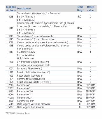
1013Stato allarmi (0 = Assente, 1 = Presente)Bit 0 = Allarme 1Bit 1 = Allarme 2
RO 0
1014
Riarmo manuale: scrivere 0 per riarmare tutti gli allarmi.In lettura (0 = Non riarmabile, 1 = Riarmabile)Bit 0 = Allarme 1Bit 1 = Allarme 2
R/W 0
1015 Stato allarme 1 (controllo remoto) R/W 01016 Stato allarme 2 (controllo remoto) R/W 01017 Valore uscita analogica mA (controllo remoto) R/W 01018 Valore uscita analogica Volt (controllo remoto) R/W 0
1019Run da seriale0 = Uscite inibite1 = Uscite attive
R/W 1
1020Hold da seriale0 = Ingresso analogito attivo1 = Ingresso analogico in Hold
R/W 0
1021 Tara zero AI (scrivere 1) R/W 01022 Reset totalizzatore (scrivere 1) R/W 01023 Reset picchi (scrivere 1) R/W 01024 Somma totale (scrivere 1) R/W 01025 Reset somma totale (scrivere 1) R/W 02001 Parametro 1 R/W EEPROM2002 Parametro 2 R/W EEPROM2150 Parametro 150 R/W EEPROM4001 Parametro 1* R/W EEPROM4002 Parametro 2* R/W EEPROM4150 Parametro 150* R/W EEPROM5001 Data logger: versione firmware R EEPROM5002 Data logger: tipo sensore R EEPROM

Manuale d’uso - STR550 71
ModbusAddress Descrizione Read
OnlyReset value
5003 Data logger: punto decimale R EEPROM5004 Data logger: unità di misura R EEPROM5005 Data logger: tempo di campionamento in secondi R EEPROM
5006
Data logger: flag fine memoria. 0 indica che c’è ancora memoria disponibile. 1 indica che la memoria è terminata e lo strumento ha ricominciato a salvare i dati dall’indirizzo 5017
R EEPROM
5017 Primo valore dell’ingresso analogico salvato. R EEPROM5018 Secondo valore dell’ingresso analogico salvato. R EEPROM
... ... R EEPROM7561 Ultimo valore dell’ingresso analogico salvato. R EEPROM
* I parametri modificati usando gli indirizzi seriali dal 4001 al 4150, vengono salvati in eeprom solamente dopo 10” dall’ultima scrittura di uno dei parametri.

72 STR550 - Manuale d’uso
10 Configurazione
10.1 Modifica parametro di configurazionePer parametri di configurazione vedi par. 11
Premere Effetto Eseguire
1 ConfigurazioneSu display compare password 0000 con la 1a cifra selezionata
2 e Si modifica la cifra selezionata e si passa alla successiva con il tasto
Inserire la password 1234
3Sel
per confermaSul display compaiono i nomi dei gruppi di parametri
4 e Scorre i gruppi di parametri
5
Sel entra nel
gruppo di paramentri
Sul display compare la lista dei parametri apparteneti al gruppo selezionato
e per selezionare il parametro da modificare
6
Sel entra nella modalità
di modifica parametro
Sul display compare la lista di selezioni possibili del parametro o il valore numerico del parametro
e per modificare il parametro. Per parametri di tipo numerico con il tasto è possibile modificare cifra per cifra. Sel per confermare la modifica. per uscire senza modificare.
10.2 Caricamento valori di defaultInserendo la password 9999 si caricano le impostazioni di fabbrica dello strumento.

Manuale d’uso - STR550 73
11 Tabella parametri di configurazioneL’elenco dei parametri sotto riportato è completo; alcuni di questi non appariranno sui modelli che non dispongono delle relative risorse Hardware.
11.1 Ingresso analogicoParametri per la configurazione dell’ingresso analogico
1 Tipo sensoreConfigurazione ingresso analogico/selezione sensoreTermocoppia K (Default) -260 °C..1360 °CTermocoppia S -40 °C..1760 °CTermocoppia R -40 °C..1760 °CTermocoppia J -200 °C..1200 °CTermocoppia T -260 °C..400 °CTermocoppia E -260 °C..1000 °CTermocoppia N -260 °C..1280 °CTermocoppia B +80 °C..1820 °CPT100 -200 °C..600 °CNI100 -60 °C..180 °CNTC 10Kohm -40 °C..125 °CPTC 1Kohm -50 °C..150 °CPT500 -100 °C..600 °CPT1000 -100 °C..600 °C0..10 V0..20 mA4..20 mA0..60 mVPot. max. 6 KOhmPot. max. 150 KOhm

74 STR550 - Manuale d’uso
2 Punto decimaleSeleziona il tipo di decimale visualizzato0 Default0.0 1 Decimale0.00 2 Decimali0.000 3 Decimali
3 Unità di misura Determina l’unità di misura visualizzata°C (Default)°FKVmVAmABarmBarpsiPamm
cmdmmkmingkgqtozlbm/s
m/mm/hl/sl/ml/hm3/sm3/mm3/hrpm%rhph
4 Limite inferiore V/ILimite inferiore range AN1 solo per normalizzati. Es: con ingresso 4..20 mA questo parametro assume il valore associato a 4 mA-32767 + 32767 [digit1], Default: 0.
5 Limite superiore V/I Limite superiore range AN1 solo per normalizzati. Es: con ingresso 4..20 mA questo parametro assume il valore associato a 20 mA-32767 + 32767 [digit1], Default: 1000.

Manuale d’uso - STR550 75
6 Calibrazione offsetCalibrazione offset. Valore che si somma o sottrae al processo visualizzato (es: normalmente corregge il valore di temperatura ambiente)-1000..+1000 [digit1] per sensori normalizzati e potenziometri.-100.0..+100.0 (gradi.decimi per sensori di temperatura). Default 0.0.
7 Calibrazione guadagnoCalibrazione guadagno AI1. Valore che si moltiplica al processo per eseguire calibrazione sul punto di lavoro-100.0%..+100.0%, Default: 0.0es: per correggere la scala di lavoro da 0..1000°C che visualizza 0..1010°C, fissare il parametro a -1.0
8 Latch OnImpostazione automatica dei limiti per ingressi normalizzati e potenziometri. Disabilitato (Default)AbilitatoAcquisizione
9 TotalizzatoreVisualizza, nella corrispondente pagina, il volume di fluido complessivo considerando il segnale del sensore come valore unità/tempo. (esempio: se il sensore collegato ha un’uscita 4..20mA con fondoscala 2000m³/ora, si dovrà impostare il parametro 8 “Totalizzatore“ come , “Ora” ed il display visualizzerà il volume di fluido complessivo dall’ultimo segnale di RESET/START all’istante correnteDisabilitato Il display visualizza il processo (Default)Secondo Il display visualizza la portata in unità/sMinuto Il display visualizza la portata in unità/minOra Il display visualizza la portata in unità/ora

76 STR550 - Manuale d’uso
10 Funzione sommaAbilita la funzione somma e la corrispondente pagina. Permette di sommare ad una variabile il valore del processoDisabilitata (Default)Abilitata
11 SalvataggioAbilita il salvataggio in eeprom dei valori di picco, del totalizzatore, della funzione somma e della tara di zero. Se disabilitato, all’accensione, i valori menzionati partono dal valore 0. Il salvataggio avviene in maniera automatica ogni 5 minutiDisabilitato (Default)Abilitato
12 Filtro conversioneFiltro ADC: numero di letture del sensore di ingresso per il calcolo della media che definisce il valore del processo. NB: con l’aumento delle medie rallenta la velocità del loop di controllo1..15 medie Default: 10.
13 Frequenza conversioneFrequenza di campionamento del convertitore analogico-digitale.NB: Aumentando la velocità di conversione diminuisce la stabilità di lettura (es: per transitori veloci come la pressione consigliabile aumentare la frequenza di campionamento)242 Hz 4.2ms (Massima velocità di conversione)123 Hz 8.2ms62 Hz 16.1ms50 Hz 20ms39 Hz 25.6ms33.2 Hz 30.1ms19.6 Hz 51ms

Manuale d’uso - STR550 77
16.7 Hz (Default) 59.9ms Ideale per filtraggio disturbi 50 / 60 Hz12.5 Hz 80ms10 Hz 100ms8.33 Hz 120ms6.25 Hz 160ms4.17 Hz 240ms (Minima velocità di conversione)
11.2 V/I personalizzatoParametri per la configurazione dell’ingresso personalizzabile.
17 V/I personalizzatoSeleziona il tipo di linearizzazione per l’ingresso analogico se impostato come normalizzatoLim. inf e sup. L’ingresso verrà linearizzato dai parametri 4 e 5 (Default)16 spezzate L‘ingresso verrà linearizzato dai valori dei parametri 18-49
18 01-Valore ingressoDefinisce il valore dell’ingresso a cui assegnare il 1° valore personalizzato0..20000 Default: 0.
19 01-Valore personalizzatoDefinisce il 1° valore personalizzato assegnato all’ingresso-32767..32767 [Digit2] Default: 0.
20 02-Valore ingressoDefinisce il valore dell’ingresso a cui assegnare il 2° valore personalizzato0..20000 Default: 2000.
21 02-Valore personalizzatoDefinisce il 2° valore personalizzato assegnato all’ingresso-32767..32767 [Digit2] Default: 1000.

78 STR550 - Manuale d’uso
22 03-Valore ingressoDefinisce il valore dell’ingresso a cui assegnare il 3° valore personalizzato0..20000 Default: 0.
23 03-Valore personalizzatoDefinisce il 3° valore personalizzato assegnato all’ingresso-32767..32767 [Digit2] Default: 0.
24 04-Valore ingressoDefinisce il valore dell’ingresso a cui assegnare il 4° valore personalizzato0..20000 Default: 0.
25 04-Valore personalizzatoDefinisce il 4° valore personalizzato assegnato all’ingresso-32767..32767 [Digit2] Default: 0.
26 05-Valore ingressoDefinisce il valore dell’ingresso a cui assegnare il 5° valore personalizzato0..20000 Default: 0.
27 05-Valore personalizzatoDefinisce il 5° valore personalizzato assegnato all’ingresso-32767..32767 [Digit2] Default: 0.
28 06-Valore ingressoDefinisce il valore dell’ingresso a cui assegnare il 6° valore personalizzato0..20000 Default: 0.
29 06-Valore personalizzatoDefinisce il 6° valore personalizzato assegnato all’ingresso-32767..32767 [Digit2] Default: 0.

Manuale d’uso - STR550 79
30 07-Valore ingressoDefinisce il valore dell’ingresso a cui assegnare il 7° valore personalizzato0..20000 Default: 0.
31 07-Valore personalizzatoDefinisce il 7° valore personalizzato assegnato all’ingresso-32767..32767 [Digit2] Default: 0.
32 08-Valore ingressoDefinisce il valore dell’ingresso a cui assegnare il 8° valore personalizzato0..20000 Default: 0.
33 08-Valore personalizzatoDefinisce il 8° valore personalizzato assegnato all’ingresso-32767..32767 [Digit2] Default: 0.
34 09-Valore ingressoDefinisce il valore dell’ingresso a cui assegnare il 9° valore personalizzato0..20000 Default: 0.
35 09-Valore personalizzatoDefinisce il 9° valore personalizzato assegnato all’ingresso-32767..32767 [Digit2] Default: 0.
36 10-Valore ingressoDefinisce il valore dell’ingresso a cui assegnare il 10° valore personalizzato0..20000 Default: 0.
37 10-Valore personalizzatoDefinisce il 10° valore personalizzato assegnato all’ingresso-32767..32767 [Digit2] Default: 0.

80 STR550 - Manuale d’uso
38 11-Valore ingressoDefinisce il valore dell’ingresso a cui assegnare il 11° valore personalizzato0..20000 Default: 0.
39 11-Valore personalizzatoDefinisce il 11° valore personalizzato assegnato all’ingresso-32767..32767 [Digit2] Default: 0.
40 12-Valore ingressoDefinisce il valore dell’ingresso a cui assegnare il 12° valore personalizzato0..20000 Default: 0.
41 12-Valore personalizzatoDefinisce il 12° valore personalizzato assegnato all’ingresso-32767..32767 [Digit2] Default: 0.
42 13-Valore ingressoDefinisce il valore dell’ingresso a cui assegnare il 13° valore personalizzato0..20000 Default: 0.
43 13-Valore personalizzatoDefinisce il 13° valore personalizzato assegnato all’ingresso-32767..32767 [Digit2] Default: 0.
44 14-Valore ingressoDefinisce il valore dell’ingresso a cui assegnare il 14° valore personalizzato0..20000 Default: 0.
45 14-Valore personalizzatoDefinisce il 14° valore personalizzato assegnato all’ingresso-32767..32767 [Digit2] Default: 0.

Manuale d’uso - STR550 81
46 15-Valore ingressoDefinisce il valore dell’ingresso a cui assegnare il 15° valore personalizzato0..20000 Default: 0.
47 15-Valore personalizzatoDefinisce il 15° valore personalizzato assegnato all’ingresso-32767..32767 [Digit2] Default: 0.
48 16-Valore ingressoDefinisce il valore dell’ingresso a cui assegnare il 16° valore personalizzato0..20000 Default: 0.
49 16-Valore personalizzatoDefinisce il 16° valore personalizzato assegnato all’ingresso-32767..32767 [Digit2] Default: 0.
11.3 Allarme 1Parametri per la configurazione dell’allarme 1
54 Tipo di allarmeSelezione del tipo di allarme 1Disabilitato (Default)AssolutoBandaIngr. digitale 1Ingr. digitale 2L.B.A.Ctrl remoto

82 STR550 - Manuale d’uso
55 Tipo contattoSeleziona il tipo di contatto per l’uscita allarme 1 e il tipo interventoNorm. aperto (Default)Norm. chiusoN.A. - C.B.A.N.C. - C.B.A.
56 Soglia allarmeDetermina il setpoint dell’allarme 1-32767..+32767 [Digit2] (gradi.decimi per sensori di temperatura), Default: 0.0.
57 Soglia deviazioneDetermina la deviazione dal setpoint di allarme 1 per l’allarme di banda 0..+32767 [Digit2] (gradi.decimi per sensori di temperatura), Default: 0.0.
58 IsteresiIsteresi allarme 1-1000..+1000 [Digit2] (gradi.decimi per sensori di temperatura), Default: 0.0.
59 Tipo di riarmoTipo di reset del contatto dell’allarme 1Automatico (Default)Manuale Riarmo/reset manuale da tastieraMan. memorizzato Mantiene lo stato del relè anche dopo un’eventuale
mancanza di alimentazione
60 Contatto erroreStato del contatto per l’uscita di allarme 1 in caso di erroreAperto (Default)Chiuso

Manuale d’uso - STR550 83
61 SegnalazioneDetermina lo stato della retroilluminazione durante l’allarme 1Nessuna (Default)RossoVerdeGialloBluViolaAzzurroBianco
62 Ritardo interventoRitardo allarme 1.-3600..+3600 secondi. Default: 0Negativo: ritardo in fase di uscita dall’allarme.Positivo: ritardo in fase di entrata dell’allarme.
63 Limite inferioreLimite inferiore impostabile per il setpoint dell’allarme 1 -32767..+32767 [Digit2] (gradi.decimi per sensori di temperatura). Default: 0.
64 Limite superioreLimite superiore impostabile per il setpoint dell’allarme 1-32767..+32767 [Digit2] (gradi.decimi per sensori di temperatura). Default: 1000.
65 ProtezioneProtezione set allarme 1. Non consente all’utente di variare il setpointLibero Modificabile dall’utente (Default)Bloccato ProtettoNascosto Protetto e non visualizzato

84 STR550 - Manuale d’uso
11.4 Allarme 2Parametri per la configurazione dell’allarme 2.
69 Tipo di allarmeSelezione del tipo di allarme 2Disabilitato (Default)AssolutoBandaIngr. digitale 1Ingr. digitale 2L.B.A.Ctrl remoto
70 Tipo contattoSeleziona il tipo di contatto per l’uscita allarme 2 e il tipo interventoNorm. aperto (Default)Norm. chiusoN.A. - C.B.A.N.C. - C.B.A.
71 Soglia allarmeDetermina il setpoint dell’allarme 2-32767..+32767 [Digit2] (gradi.decimi per sensori di temperatura), Default: 0.0.
72 Soglia deviazioneDetermina la deviazione dal setpoint di allarme 2 per l’allarme di banda0..+32767 [Digit2] (gradi.decimi per sensori di temperatura), Default: 0.0.
73 IsteresiIsteresi allarme 2-1000..+1000 [Digit2] (gradi.decimi per sensori di temperatura), Default: 0.0.

Manuale d’uso - STR550 85
74 Tipo di riarmoTipo di reset del contatto dell’allarme 2Automatico (Default)Manuale Riarmo/reset manuale da tastieraMan.memorizzato Mantiene lo stato del relè anche dopo un’eventuale
mancanza di alimentazione
75 Contatto erroreStato del contatto per l’uscita di allarme 2 in caso di erroreAperto (Default)Chiuso
76 SegnalazioneDetermina lo stato della retroilluminazione durante l’allarme 2Nessuna (Default)RossoVerdeGialloBluViolaAzzurroBianco
77 Ritardo interventoRitardo allarme 2. -3600..+3600 secondi. Default: 0Negativo: ritardo in fase di uscita dall’allarme.Positivo: ritardo in fase di entrata dell’allarme.
78 Limite inferioreLimite inferiore impostabile per il setpoint dell’allarme 2 -32767..+32767 [Digit2] (gradi.decimi per sensori di temperatura). Default: 0.

86 STR550 - Manuale d’uso
79 Limite superioreLimite superiore impostabile per il setpoint dell’allarme 2-32767..+32767 [Digit2] (gradi.decimi per sensori di temperatura). Default: 1000.
80 ProtezioneProtezione set allarme 2. Non consente all’utente di variare il setpointLibero Modificabile dall’utente (Default)Bloccato ProtettoNascosto Protetto e non visualizzato
11.5 Display
84 LinguaSeleziona la linguaEnglish (Default)ItalianoDeutschFrancaisEspañol
85 ColoreSeleziona il colore della retroilluminazioneBianco (Default)AzzurroViolaBluGialloVerdeRosso

Manuale d’uso - STR550 87
86 ContrastoDetermina il valore del contrasto per l’LCD0%..100%, Default: 35%.
87 ReverseAbilita il reverse dell’LCDDisabilitato (Default)Abilitato
88 Timeout displayDetermina il tempo di accensione della retroilluminazione dell’LCDSempre acceso (Default)15 secondi30 secondi1 minuto
2 minuti5 minuti10 minuti
30 minuti1 ora
89 Verso displayDetermina l’orientamento di visualizzazione dell’LCDOrizzontale (Default)Verticale
90 Pagina inizialeDetermina la pagina visualizzata all’accensione dopo lo splash screenProcesso (Default)GraficoValori di piccoTotalizzatoreFunzione somma
11.6 Ingresso digitale 1Parametri per la configurazione dell’ingresso digitale 1.

88 STR550 - Manuale d’uso
95 Funzione ingressoSeleziona il tipo di funzione eseguita dall’ingresso digitale 1Disabilitato (Default)Abilita usciteHoldTara zero (AI) (funzionamento ad impulso)Riarmo allarmiReset totalizz. (funzionamento ad impulso)Reset picchiSomma totale (funzionamento ad impulso)Reset somma (funzionamento ad impulso)Blocco config.
96 Tipo contattoSeleziona il contatto a riposo dell’ingresso digitale 1Norm. aperto (Default) Esegue la funzione con contatto chiusoNorm. chiuso Esegue la funzione con contatto aperto
11.7 Ingresso digitale 2Parametri per la configurazione dell’ingresso digitale 2.
100 Funzione ingressoSeleziona il tipo di funzione eseguita dall’ingresso digitale 2Disabilitato (Default)Abilita usciteHoldTara zero (AI) (funzionamento ad impulso)Riarmo allarmiReset totalizz. (funzionamento ad impulso)Reset picchiSomma totale (funzionamento ad impulso)Reset somma (funzionamento ad impulso)Blocco config.

Manuale d’uso - STR550 89
101 Tipo contattoSeleziona il contatto a riposo dell’ingresso digitale 2Norm. aperto (Default) Esegue la funzione con contatto chiusoNorm. chiuso Esegue la funzione con contatto aperto
11.8 GraficoParametri per la configurazione della gestione trend e bar graph.
105 Tipo graficoDetermina il tipo di grafico visualizzato sulla pagina dedicataTrend (Default)Bar graph
106 Limite inferiore graficoLimite inferiore trend o bar graph-32767 + 32767 [Digit2], Default: 0.
107 Limite superiore graficoLimite superiore trend o bar graph-32767 + 32767 [Digit2], Default: 1000.
108 Tempo graficoSeleziona il tempo di campionamento del trend1..3600 secondi, Default: 60s.
109 Data loggerAbilita la registrazione del processo a tempo in eepromIl tempo di campionamento equivale al tempo di aggiornamento del trendDisabilitato (Default)Abilitato

90 STR550 - Manuale d’uso
11.9 Uscita analogica in mAParametri per la configurazione delle uscita analogica in mA
112 RitrasmissioneAbilita l’uscita analogicaDisabilitata (Default)ProcessoAllarme 1Allarme 2Ctrl remoto
113 Tipo di segnaleDetermina il tipo di segnale per l’uscita analogica in mA0..20 mA4..20 mA (Default)
114 Limite inferioreLimite inferiore range uscita analogica in mA-32767..+32767 [Digit2] (gradi.decimi per sensori di temperatura), Default: 0
115 Limite superioreLimite superiore range uscita analogica in mA-32767..+32767 [Digit2] (gradi.decimi per sensori di temperatura) Default: 1000
116 Valore erroreDetermina il valore dell’uscita analogica in mA in caso di errore0 mA (Default)4 mA20 mA

Manuale d’uso - STR550 91
11.10 Uscita analogica in VoltParametri per la configurazione delle uscita analogica in mA
119 RitrasmissioneAbilita l’uscita analogicaDisabilitata (Default)ProcessoAllarme 1Allarme 2Ctrl remoto
120 Tipo di segnaleDetermina il tipo di segnale per l’uscita analogica in Volt0..10 V (Default)
121 Limite inferioreLimite inferiore range uscita analogica in Volt-32767..+32767 [Digit2] (gradi.decimi per sensori di temperatura), Default: 0.
122 Limite superioreLimite superiore range uscita analogica in Volt-32767..+32767 [digit2] (gradi.decimi per sensori di temperatura) Default: 1000
123 Valore erroreDetermina il valore dell’uscita analogica in Volt in caso di errore0 V (Default)10 V
2 La visualizzazione del punto decimale dipende dall’impostazione del parametro “Tipo sensore” e del parametro “Punto decimale”.

92 STR550 - Manuale d’uso
11.11 Comunicazione serialeParametri per la configurazione della porta di comunicazione seriale.
126 Indirizzo SlaveSeleziona l’indirizzo dello slave per la comunicazione seriale1..254. Default: 240
127 Baud RateSeleziona il baud rate per la comunicazione seriale1.200 baud2.400 baud4.800 baud9.600 baud19.200 baud (Default)28.800 baud39.400 baud57.600 baud115.200 baud
128 Formato serialeSeleziona il formato per la comunicazione seriale8,N,1 8bit, No parity, 1 Stop bit (Default)8,E,1 8bit, Even parity, 1 Stop bit8,O,1 8bit, Odd parity, 1 Stop bit8,N,2 8bit, No parity, 2 Stop bit8,E,2 8bit, Even parity, 2 Stop bit8,O,2 8bit, Odd parity, 2 Stop bit
129 Ritardo serialeSeleziona il ritardo seriale.0..100 millisecondi. Default: 10

Manuale d’uso - STR550 93
Note / Aggiornamenti

94 STR550 - Manuale d’uso