Embed Size (px)
Citation preview

Stormy PhillipsBASICS OF LEASE AUTOMATIC
CUSTODY TRANSFER (LACT) SYSTEMS

Why is Stormy Walking Funny??

Introduction
What is a LACT system?
A LACT unit is a group of equipment designed specifically for the
unattended custody transfer between a lease and the method of
transportation to remove the liquids from the lease. In doing this the
unit must be able to provide volume and quality of the liquids, provide
for fail-safe and tamper proof operation, and meet the requirements
of accuracy deemed necessary by both parties.

Requirements for All LACT Units
When the liquid is transferred, it should be in a stable state
Volume, temperature, and pressure must be recorded in accordance with all regulations
A representative sample must be taken of the transferred liquid
Means to stop the transfer of un-merchantable liquids must be provided for
The flow rate must be controllable
Fail-safes must be provided for in the case of power loss or system failure
All parts that require calibration must be accessible for inspection be all parties
The system can have no by-pass to allow liquid to flow around the meter
The unit must be tamper-proof
Sediment and water content and density measurements shall be made by automatic samplers

Basic Layout and Major Components for
LACT Units

Major Components
• The skid – Designed to make the unit portable, stable, and serve
as a containment system
• The strainer – Should be located upstream of the meter and
charge pump. Ideally with pressure gauges on each side of the
strainer to identify blockage
• Charge pump – Ideally a centrifugal pump, design to keep the
discharge pressure to a minimum of 20 psig. Must be able to
maintain fluid pressure throughout the system in excess of the
product bubble point to prevent the formation of vapor
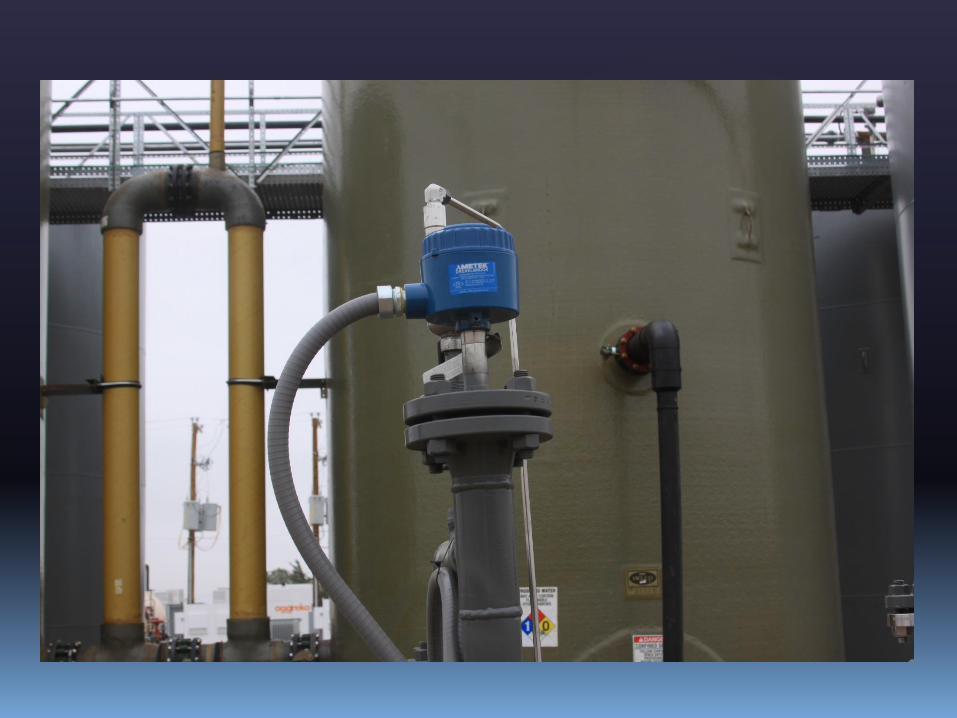
• Sediment and Water Monitor – Is used in a vertical section of the
piping, upstream of the divert valve, to identify when liquids are
not suitable for custody transfer. Controls the divert valve, and the
time-delay
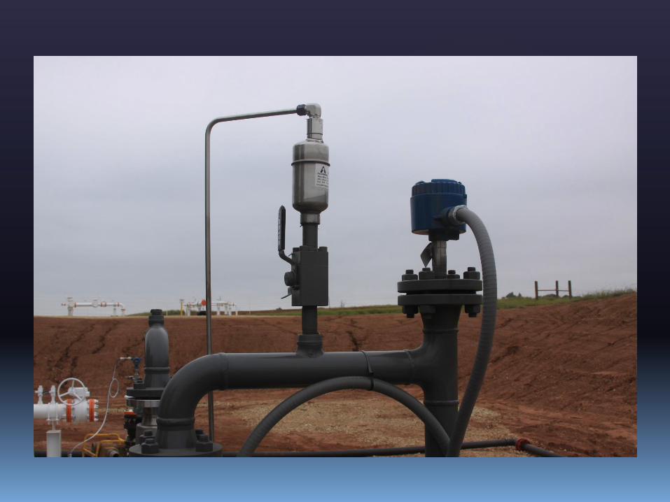
• Air/Vapor Eliminator – Located at the highest point in the piping,
upstream of the meter. Designed for the removal of small
amounts of vapor in the liquid, which is diverted off-skid
• Sampling system – Controlled via the meter


Grounding and Containment

Cathodic Protection
Vs
Stability
Pros
And
Cons
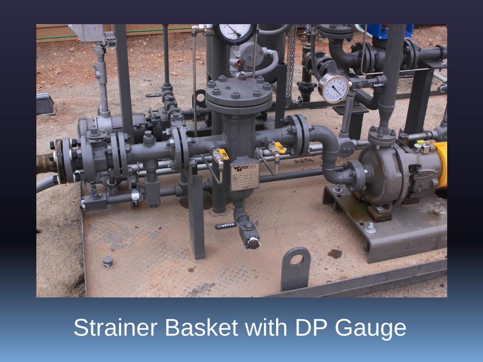
Strainer Basket with DP Gauge

Strainer Basket with DP Alarm
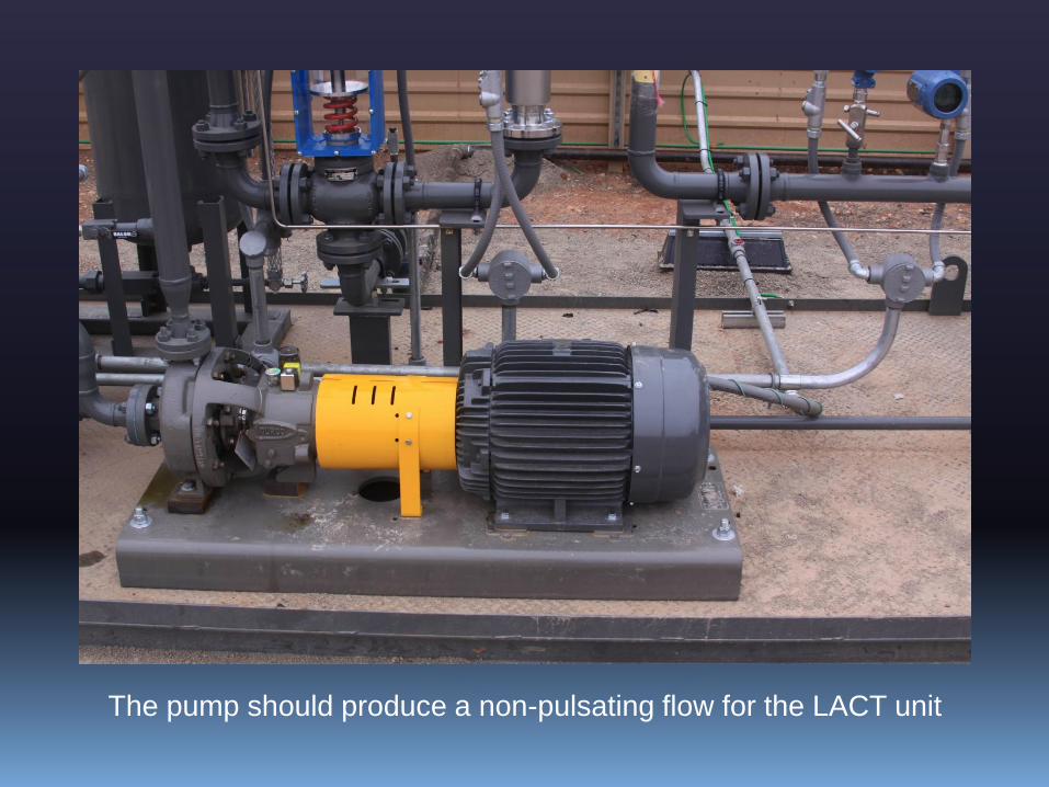
The pump should produce a non-pulsating flow for the LACT unit

S&W Detector Probe and Monitor

Accounting for a liquid run is determined on the basis
of net standard volume, which includes corrections for
meter factor, temperature, pressure, and sediment and
water content. Therefore the composite sample that is
collected during any run, must represent all liquid
delivered during that run.
Means to eliminate stratification and to assure
homogeneity of the flow stream at the point of
sampling must be part of the design.
Sampling should be proportioned to the flow rate
through the meter
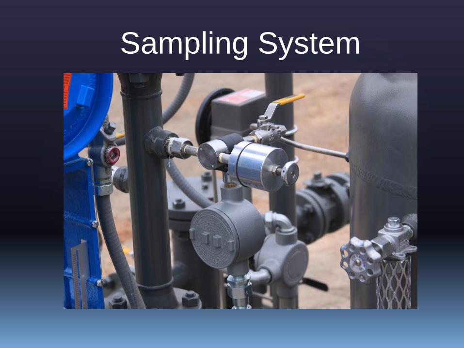
Sampling System

Insuring that the sample is representative of the fluid flow.
Sampling System

The droplet size should range between 200 -1,200 microns
(Before passing through
the static mixer)
(After passing through
the static mixer)

FLOW
- Probe cut at a 45° Degree Angle
- Probe should be in the center 1/3 of the line
Extraction Methods
Probe should be designed to resist the stresses
resulting from stream velocity conditions
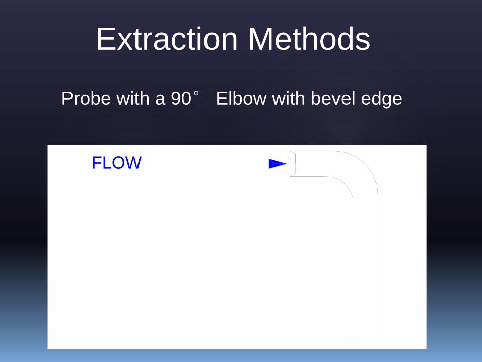
FLOW
Extraction Methods
Probe with a 90° Elbow with bevel edge
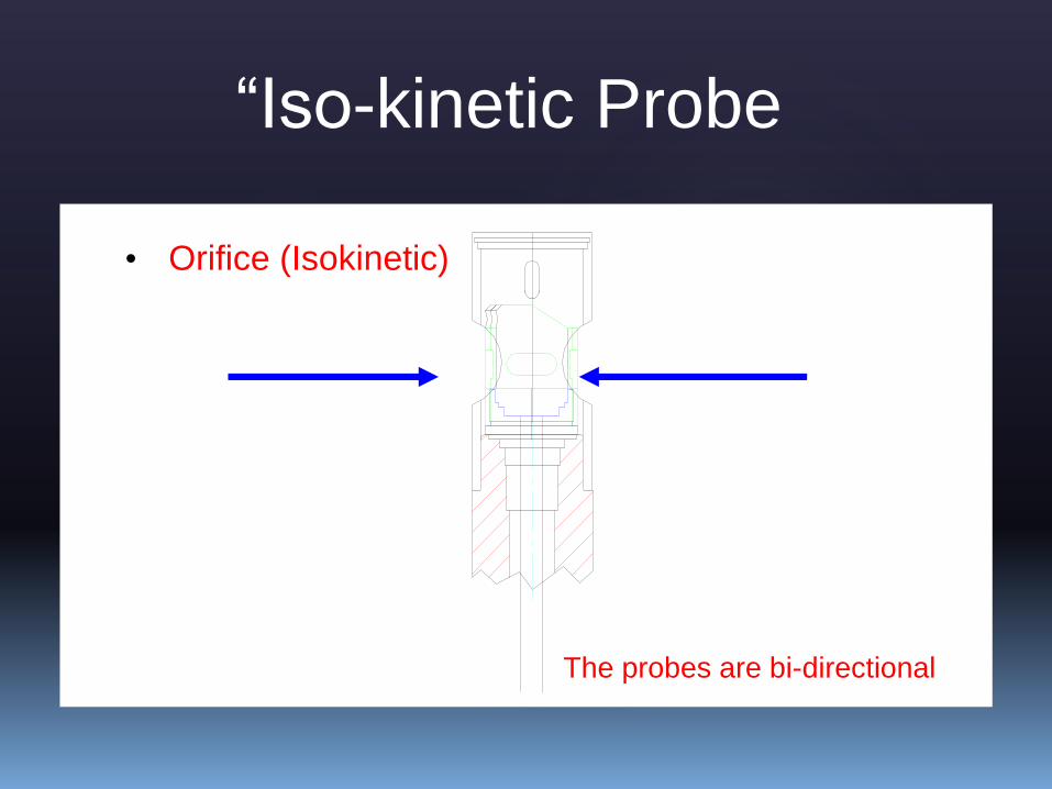
“Iso-kinetic Probe
• Orifice (Isokinetic)
The probes are bi-directional
Flow Flow
Sampling System

Sampling System

Sampling System

Sampling System

Major Components
• Divert Valve – Controlled by the S&W Monitor, it prevents
the delivery of liquids that does not conform to the contract
terms of the lease
• Fluid Meter – records the volume of product delivered
through the unit, with corrections for temperature, pressure,
and meter factor
• Proving Loop – Used to test the accuracy of the meter. All
three valves in the loop are of full open design and no
smaller than the meter. The valve on the line should be a
double block and bleed valve
• Back Pressure Valve – Used to maintain the pressure in the
system, to prevent the formation of vapor and surging
• Check Valve – To prevent the back flow of fluids in the
system

3-Way Divert Valve
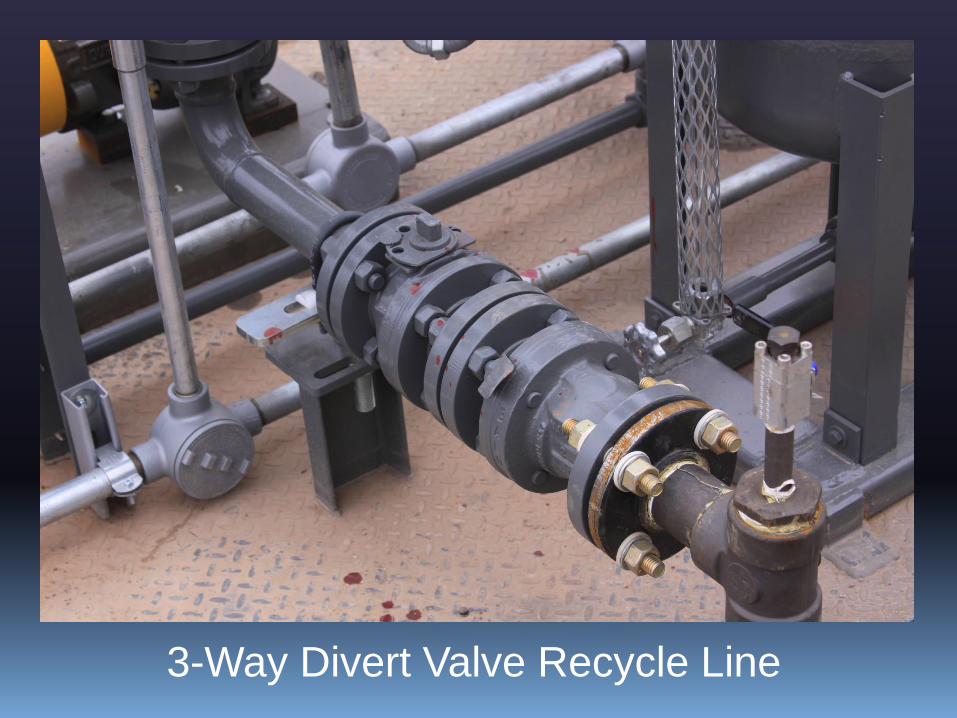
3-Way Divert Valve Recycle Line

3-Way Divert Valve Backpressure Valve

Proving Loop

Proving Loop

Double Block and Bleed Valve

Sump Box
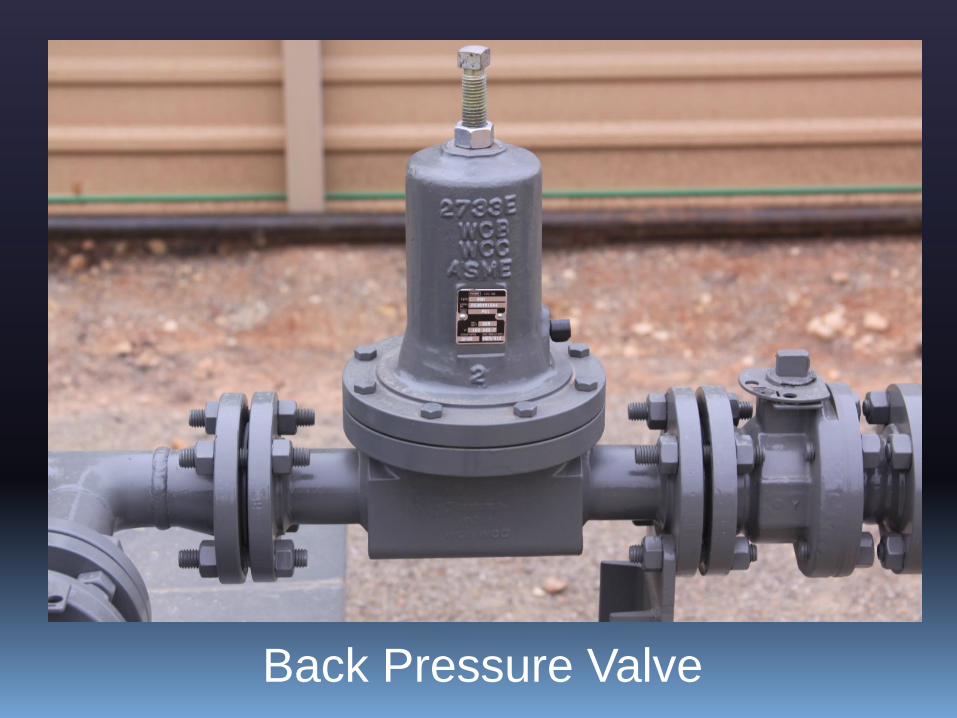
Back Pressure Valve

Conventional Turbine Meter

StrengthsWell Understood
Economical
Easy to Prove
Weaknesses
Easily Fouled or Damaged
Cavitation – Low Line Pressure or High Vapor Pressure
Flow Conditioning Uncertainties
Limited to Lower Viscosity Oils
Strengths and Weaknesses of Turbine
Meters

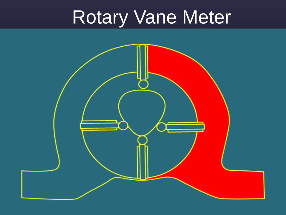
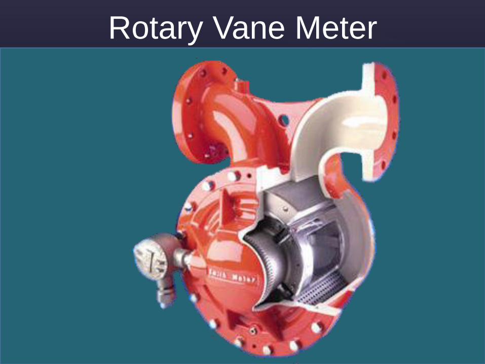
Rotary Vane Meter
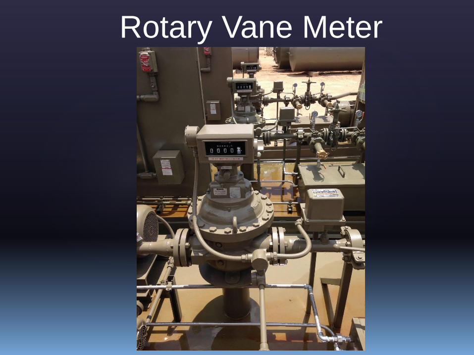
Rotary Vane Meter

Rotary Vane Meter
Rotary Vane Meter

Rotary Vane Meter
Rotary Vane Meter

Rotary Vane Meter
Rotary Vane Meter
Rotary Vane Meter
Rotary Vane Meter

Rotary Vane Meter
Rotary Vane Meter

Rotary Vane Meter
Rotary Vane Meter
Rotary Vane Meter
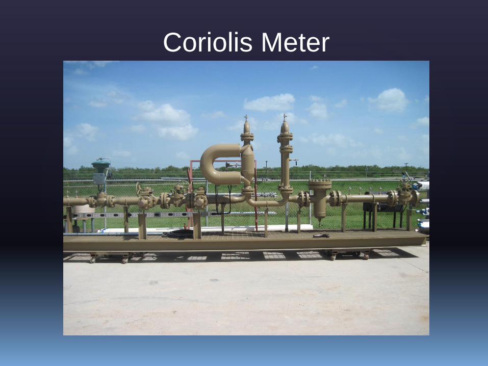
Coriolis Meter

Coriolis Meter
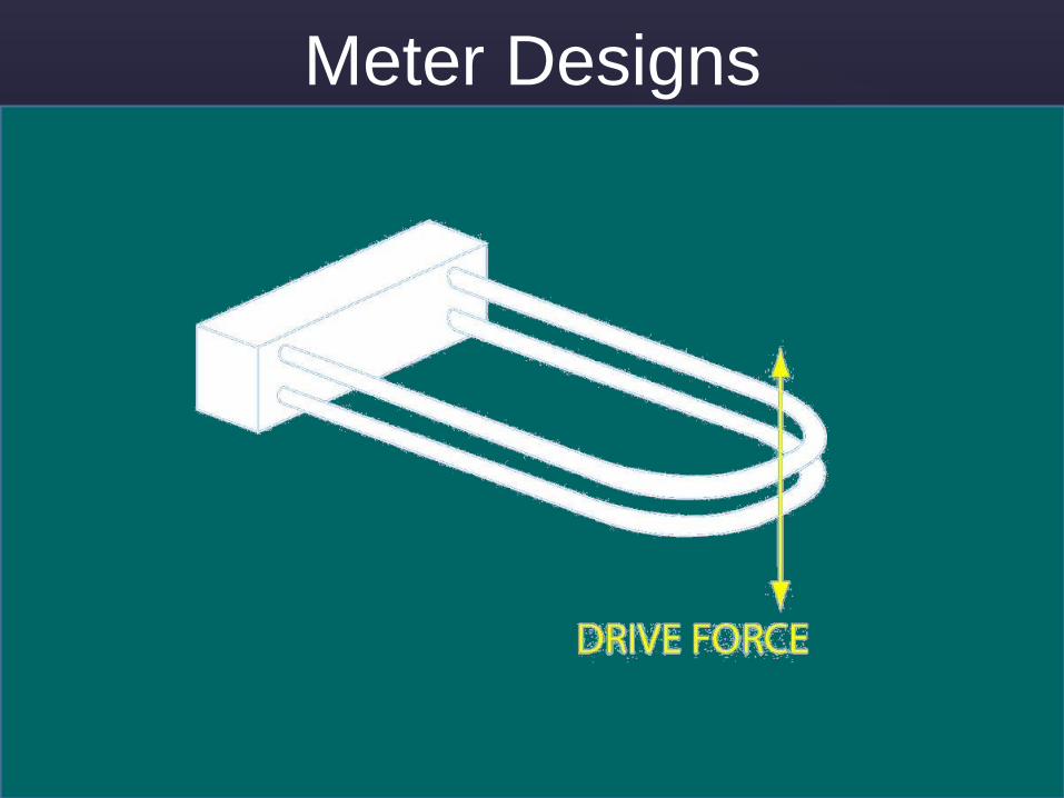
Meter Designs

Components of a Coriolis MeterDrive Coil
Sense Coil
Sense Coil

Coil Details
Sense Coil
Drive Coil

Coriolis Meter