Embed Size (px)
Citation preview
Stormwater Management
Guidebook
Prepared for:
District Department of the Environment
Watershed Protection Division
District of Columbia
Prepared by:
Center for Watershed Protection
8390 Main Street
Ellicott City, MD 21043
July 2013


iii
Acknowledgements
A major undertaking such as this requires the dedication and cooperative efforts of many individuals. Dr. Hamid
Karimi, Director of Natural Resources; Sheila Besse, Associate Director of Watershed Protection; Jeff Seltzer,
Associate Director of Stormwater Management; and Timothy Karikari, Branch Chief of Technical Services deserve
credit for their overall leadership and support for this project. Their willingness to allow staff to pursue ideas to their
fullest and provide necessary time, resources, and managerial support laid the foundation for much innovation.
Project Manger
Rebecca C. Stack, DDOE-Technical Services
Lead Authors
Greg Hoffmann, P.E., Center for Watershed Protection
Rebecca C. Stack, DDOE-Technical Services
Brian Van Wye, DDOE-Stormwater Management
Editor
Sherry Schwechten, DDOE-Stormwater Management
Contributors and Peer Reviewers
Joseph Battiata, P.E., Center for Watershed Protection
Evan Branosky, DDOE-Stormwater Management
Gerald Brock, Ph.D., George Washington University
Josh Burch, DDOE-Planning and Restoration
Collin R. Burrell, DDOE-Water Quality
Walter Caldwell, DDOE-Inspection and Enforcement
Jonathan Champion, DDOE-Stormwater Management
Reid Christianson P.E., Ph.D., Center for Watershed Protection
Laine Cidlowski, Office of Planning
Richard DeGrandchamp, Ph.D., University of Colorado/Scientia Veritas
Elias Demessie, DDOE-Technical Services
Diane Douglas, DDOE-Water Quality
Matthew Espie, DDOE-Stormwater Management
Alex Forasté, Williamsburg Environmental Group, Inc.
Laura Gardner, Center for Watershed Protection
Timothy Karikari, P.E., CPESC, CFM, DDOE-Technical Services
Melissa Keeley, Ph.D., George Washington University
Tim Klien, DDOE-Inspection and Enforcement
Sarah Lawson, Ph.D., Rainwater Management Solutions
Leah Lemoine, DDOE-Planning and Restoration
Susan Libes, Ph.D., Coastal Carolina University, Conway, SC
Kelly (Collins) Lindow, P.E., (Center for Watershed Protection)/RK&K
Dennis Lye, Ph.D., US EPA
Massoud Massoumi, DDOE-Technical Services
Abdi Musse, P.E., DDOE-Technical Services
Phetmano Phannavong, P.E., C.F.M., DDOE-Technical Services
Philip C. Reidy, P.E., Geosyntec Consultants
Stephen Reiling, DDOE-Planning and Restoration
Emily Rice, DDOE-Stormwater Management
Tom Schueler, Chesapeake Bay Stormwater Network
Jeff Seltzer, P.E., DDOE-Stormwater Management
Tanya Spano, MWCOG-Water Resources
Bill Stack, P.E., Center for Watershed Protection
Meredith Upchurch, DDOT-Stormwater
June M. Weintraub, ScD, San Francisco Department of Public Health


v
Preface
Technical information regarding future updates to the District of Columbia Stormwater
Management Guidebook will be available at http://ddoe.dc.gov/publication/stormwater-
guidebook. Notices regarding future versions of the manual will be posted on this website.
Future versions are expected to occur, at most, once a year.


vii
Contents
Acknowledgements .................................................................................................................................... iii
Preface .......................................................................................................................................................... v
List of Tables ............................................................................................................................................ xvi
List of Figures ......................................................................................................................................... xviii
List of Equations ....................................................................................................................................... xx
Chapter 1 Introduction to the Stormwater Management Guidebook ............................................. 1
1.1 Introduction .................................................................................................................................. 1
1.2 Purpose and Scope ........................................................................................................................ 1
1.3 Impacts of Urban Runoff .............................................................................................................. 2
1.3.1 Hydrologic Impacts ............................................................................................................... 2
1.3.2 Water Quality Impacts .......................................................................................................... 4
1.4 References .................................................................................................................................... 6
Chapter 2 Minimum Control Requirements ...................................................................................... 7
2.1 District of Columbia Stormwater Management Performance Requirements ............................... 7
2.2 Stormwater Retention Volume ..................................................................................................... 9
2.3 Water Quality Treatment Volume .............................................................................................. 13
2.4 Extreme Flood Requirements ..................................................................................................... 20
2.5 Minimum Criteria for Determining Extreme Flood Requirements ............................................ 20
2.6 Additional Stormwater Management Requirements ................................................................... 22
2.7 Hydrology Methods .................................................................................................................... 22
2.8 Acceptable Urban BMP Options ................................................................................................ 23
Chapter 3 Stormwater Best Management Practices (BMPs) ......................................................... 27
3.1 Standard Best Management Practice Design Guidance Format ................................................. 27
3.2 Green Roofs ................................................................................................................................ 29
3.2.1 Green Roof Feasibility Criteria ........................................................................................... 29
3.2.2 Green Roof Conveyance Criteria ........................................................................................ 30
3.2.3 Green Roof Pretreatment Criteria ....................................................................................... 31
3.2.4 Green Roof Design Criteria ................................................................................................ 31
3.2.5 Green Roof Landscaping Criteria ....................................................................................... 35
3.2.6 Green Roof Construction Sequence .................................................................................... 37
3.2.7 Green Roof Maintenance Criteria ....................................................................................... 39
3.2.8 Green Roof Stormwater Compliance Calculations ............................................................. 40
3.2.9 References ........................................................................................................................... 40
3.3 Rainwater Harvesting ................................................................................................................. 43

viii
3.3.1 Rainwater Harvesting Feasibility Criteria ........................................................................... 45
3.3.2 Rainwater Harvesting Conveyance Criteria ........................................................................ 47
3.3.3 Rainwater Harvesting Pretreatment Criteria ....................................................................... 48
3.3.4 Rainwater Harvesting Design Criteria ................................................................................ 50
3.3.5 Rainwater Harvesting Landscaping Criteria ....................................................................... 62
3.3.6 Rainwater Harvesting Construction Sequence .................................................................... 62
3.3.7 Rainwater Harvesting Maintenance Criteria ....................................................................... 63
3.3.8 Rainwater Harvesting: Stormwater Compliance Calculations ............................................ 65
3.3.9 References ........................................................................................................................... 65
3.4 Impervious Surface Disconnection ............................................................................................. 67
3.4.1 Impervious Surface Disconnection Feasibility Criteria ...................................................... 69
3.4.2 Impervious Surface Disconnection Conveyance Criteria ................................................... 70
3.4.3 Impervious Surface Disconnection Pretreatment Criteria ................................................... 70
3.4.4 Impervious Surface Disconnection Design Criteria ............................................................ 70
3.4.5 Impervious Surface Disconnection Landscaping Criteria ................................................... 74
3.4.6 Impervious Surface Disconnection Construction Sequence ............................................... 74
3.4.7 Impervious Surface Disconnection Maintenance Criteria .................................................. 75
3.4.8 Disconnection Stormwater Compliance Calculations ......................................................... 76
3.4.9 References ........................................................................................................................... 77
3.5 Permeable Pavement Systems .................................................................................................... 79
3.5.1 Permeable Pavement Feasibility Criteria ............................................................................ 80
3.5.2 Permeable Pavement Conveyance Criteria ......................................................................... 82
3.5.3 Permeable Pavement Pretreatment Criteria ........................................................................ 83
3.5.4 Permeable Pavement Design Criteria.................................................................................. 83
3.5.5 Permeable Pavement Landscaping Criteria ........................................................................ 90
3.5.6 Permeable Pavement Construction Sequence ..................................................................... 90
3.5.7 Permeable Pavement Maintenance Criteria ........................................................................ 95
3.5.8 Permeable Pavement Stormwater Compliance Calculations .............................................. 97
3.5.9 References ........................................................................................................................... 98
3.6 Bioretention ................................................................................................................................ 99
3.6.1 Bioretention Feasibility Criteria ........................................................................................ 101
3.6.2 Bioretention Conveyance Criteria ..................................................................................... 104
3.6.3 Bioretention Pretreatment Criteria .................................................................................... 105
ix
3.6.4 Bioretention Design Criteria ............................................................................................. 106
3.6.5 Bioretention Landscaping Criteria .................................................................................... 118
3.6.6 Bioretention Construction Sequence ................................................................................. 122
3.6.7 Bioretention Maintenance Criteria .................................................................................... 124
3.6.8 Bioretention Stormwater Compliance Calculations .......................................................... 126
3.6.9 References ......................................................................................................................... 127
3.7 Filtering Systems ...................................................................................................................... 129
3.7.1 Filtering Feasibility Criteria .............................................................................................. 138
3.7.2 Filtering Conveyance Criteria ........................................................................................... 139
3.7.3 Filtering Pretreatment Criteria .......................................................................................... 139
3.7.4 Filtering Design Criteria ................................................................................................... 140
3.7.5 Filtering Landscaping Criteria .......................................................................................... 144
3.7.6 Filter Construction Sequence ............................................................................................ 144
3.7.7 Filtering Maintenance Criteria .......................................................................................... 146
3.7.8 Filtering Volume Compliance Calculations ...................................................................... 148
3.7.9 References ......................................................................................................................... 148
3.8 Infiltration ................................................................................................................................. 149
3.8.1 Infiltration Feasibility Criteria .......................................................................................... 152
3.8.2 Infiltration Conveyance Criteria ....................................................................................... 154
3.8.3 Infiltration Pretreatment Criteria ....................................................................................... 154
3.8.4 Infiltration Design Criteria ................................................................................................ 155
3.8.5 Infiltration Landscaping Criteria ....................................................................................... 159
3.8.6 Infiltration Construction Sequence ................................................................................... 159
3.8.7 Infiltration Maintenance Criteria....................................................................................... 161
3.8.8 Infiltration Stormwater Compliance Calculations ............................................................ 162
3.8.9 References ......................................................................................................................... 163
3.9 Open Channel Systems ............................................................................................................. 165
3.9.1 Open Channel Feasibility Criteria ..................................................................................... 168
3.9.2 Open Channel Conveyance Criteria .................................................................................. 171
3.9.3 Open Channel Pretreatment Criteria ................................................................................. 171
3.9.4 Open Channel Design Criteria .......................................................................................... 172
3.9.5 Open Channel Landscaping Criteria ................................................................................. 180
3.9.6 Open Channel Construction Sequence .............................................................................. 181

x
3.9.7 Open Channel Maintenance Criteria ................................................................................. 183
3.9.8 Open Channel Stormwater Compliance Calculations ....................................................... 184
3.9.9 References ......................................................................................................................... 185
3.10 Ponds ........................................................................................................................................ 187
3.10.1 Pond Feasibility Criteria ................................................................................................... 189
3.10.2 Pond Conveyance Criteria ................................................................................................ 192
3.10.3 Pond Pretreatment Criteria ................................................................................................ 193
3.10.4 Pond Design Criteria ......................................................................................................... 193
3.10.5 Pond Landscaping Criteria ................................................................................................ 198
3.10.6 Pond Construction Sequence ............................................................................................ 199
3.10.7 Pond Maintenance Criteria ................................................................................................ 201
3.10.8 Pond Stormwater Compliance Calculations ...................................................................... 203
3.10.9 References ......................................................................................................................... 203
3.11 Wetlands ................................................................................................................................... 205
3.11.1 Wetland Feasibility Criteria .............................................................................................. 207
3.11.2 Wetland Conveyance Criteria ........................................................................................... 209
3.11.3 Wetland Pretreatment Criteria .......................................................................................... 210
3.11.4 Wetland Design Criteria .................................................................................................... 210
3.11.5 Wetland Construction Sequence ....................................................................................... 213
3.11.6 Wetland Landscaping Criteria .......................................................................................... 216
3.11.7 Wetland Maintenance Criteria .......................................................................................... 220
3.11.8 Wetland Stormwater Compliance Calculations ................................................................ 221
3.11.9 References ......................................................................................................................... 222
3.12 Storage Practices ....................................................................................................................... 223
3.12.1 Storage Feasibility Criteria ............................................................................................... 225
3.12.2 Storage Conveyance Criteria ............................................................................................ 227
3.12.3 Storage Pretreatment Criteria ............................................................................................ 228
3.12.4 Storage Design Criteria ..................................................................................................... 229
3.12.5 Storage Landscaping Criteria ............................................................................................ 231
3.12.6 Storage Construction Sequence ........................................................................................ 231
3.12.7 Storage Maintenance Criteria ............................................................................................ 233
3.12.8 Storage Volume Compliance Calculations ....................................................................... 234
3.12.9 References ......................................................................................................................... 234
xi
3.13 Proprietary Practices ................................................................................................................. 237
3.13.1 Proprietary Practice Feasibility Criteria ............................................................................ 237
3.13.2 Proprietary Practice Conveyance Criteria ......................................................................... 237
3.13.3 Proprietary Practice Pretreatment Criteria ........................................................................ 237
3.13.4 Proprietary Practice Design Criteria ................................................................................. 237
3.13.5 Proprietary Practice Landscaping Criteria ........................................................................ 238
3.13.6 Proprietary Practice Construction Sequence ..................................................................... 238
3.13.7 Proprietary Practice Maintenance Criteria ........................................................................ 238
3.13.8 Proprietary Practice Stormwater Compliance Calculations .............................................. 239
3.14 Tree Planting and Preservation ................................................................................................. 241
3.14.1 Preserving Existing Trees During Construction ............................................................... 241
3.14.2 Planting Trees ................................................................................................................... 243
3.14.3 Tree Inspection Criteria .................................................................................................... 248
3.14.4 Tree Maintenance Criteria ................................................................................................ 248
3.14.5 Tree Stormwater Compliance Calculations ...................................................................... 249
3.14.6 References ......................................................................................................................... 250
Chapter 4 Selecting and Locating the Most Effective Stormwater Best Management Practice System .......................................................................................................................................... 253
4.1 Choosing Stormwater Management Best Practices (BMPs) .................................................... 253
4.2 Regulatory Compliance ............................................................................................................ 254
4.3 Land Use Factors ...................................................................................................................... 255
4.4 Physical Feasibility Factors ...................................................................................................... 257
4.5 Community and Environmental Factors ................................................................................... 259
4.6 Location and Permitting Considerations .................................................................................. 263
4.7 References ................................................................................................................................ 265
Chapter 5 Administration of Stormwater Management Rules .................................................... 267
5.1 Stormwater Management Plans ................................................................................................ 267
5.1.1 Submittal and Review Process of Stormwater Management Plans ................................... 267
5.1.2 Resubmission of Stormwater Management Plans ............................................................. 273
5.2 Administration .......................................................................................................................... 274
5.2.1 Approval Requirements .................................................................................................... 274
5.2.2 Fees ................................................................................................................................... 274
5.3 Inspection Requirements .......................................................................................................... 274
5.3.1 Inspection Schedule and Reports ...................................................................................... 274
5.3.2 Inspection Requirements Before and During Construction .............................................. 275

xii
5.3.3 Final Construction Inspection Reports .............................................................................. 277
5.3.4 Inspection for Preventive Maintenance ............................................................................. 277
5.4 Maintenance .............................................................................................................................. 277
5.4.1 Maintenance Responsibility .............................................................................................. 277
5.4.2 Maintenance Agreement ................................................................................................... 278
5.5 Exemptions ............................................................................................................................... 278
5.6 Supporting Forms ..................................................................................................................... 279
5.7 Flow Diagram of Plan Review Process .................................................................................... 289
Chapter 6 Use of Off-Site Retention by Regulated Sites ............................................................... 295
6.1 Off-Site Retention Overview .................................................................................................... 295
6.2 Off-Site Retention via Stormwater Retention Credits .............................................................. 296
6.3 Off-Site Retention via In-Lieu Fee ........................................................................................... 297
6.4 Forms for Use of Off-site Retention ......................................................................................... 297
Chapter 7 Generation, Certification, Trading, and Retirement of Stormwater Retention Credits .......................................................................................................................................... 299
7.1 Stormwater Retention Credits Overview .................................................................................. 299
7.2 Eligibility Requirements ........................................................................................................... 299
7.2.1 Eligibility Requirements: Retention Volume .................................................................... 300
7.2.2 Eligibility Requirements: Design and Installation ............................................................ 301
7.2.3 Eligibility Requirements: Inspection................................................................................. 302
7.2.4 Eligibility Requirements: Maintenance ............................................................................. 302
7.3 Certification of Stormwater Retention Credits ......................................................................... 302
7.4 Format of SRC Serial Numbers ................................................................................................ 304
7.5 Failure to Maintain Retention after Certification of Stormwater Retention Credits................. 304
7.6 Buying and Selling Stormwater Retention Credits ................................................................... 304
7.7 Voluntary Retirement of Stormwater Retention Credits .......................................................... 305
7.8 Quitting the Obligation to Maintain Retention for Stormwater Retention Credits ................... 305
7.9 Calculation of Stormwater Retention Credits ........................................................................... 305
7.10 Stormwater Retention Credit Calculation Scenarios ................................................................ 309
7.11 Forms for Stormwater Retention Credits .................................................................................. 315
Appendix A Compliance Calculations and Design Examples .......................................................... A-1
A.1 General Retention Compliance Calculator ............................................................................... A-1
A.2 Instructions for Compliance Calculations ................................................................................ A-1
A.3 Design Examples .................................................................................................................... A-10
Appendix B Maximum Extent Practicable Process for Existing Public Right-of-Way................. B-1
B.1 Maximum Extent Practicable: Overview .................................................................................. B-1

xiii
B.2 Public Right-of-Way Projects ................................................................................................... B-1
B.3 Codes ........................................................................................................................................ B-4
B.4 PROW Design Considerations ................................................................................................. B-5
B.4.1 Considerations in the Planning Process (limited to Type 1). ............................................ B-5
B.4.2 Site Assessment Considerations for the Retention Standard in PROW Projects .............. B-5
B.4.3 Fundamental Tenets of MEP for PROW ........................................................................ B-10
B.5 Design Process for PROW...................................................................................................... B-10
B.6 Summary of MEP Type 1 Submission Process ...................................................................... B-15
B.7 References .............................................................................................................................. B-16
Appendix C Off-Site Retention Forms for Regulated Sites ............................................................. C-1
Appendix D Stormwater Retention Credit Forms (Certification, Trading, and Retirement) ...... D-1
Appendix E Relief for Extraordinarily Difficult Site Conditions .................................................... E-1
E.1 Relief from Extraordinarily Difficult Site Conditions .............................................................. E-1
E.2 Submission requirements for Relief from Extraordinarily Difficult Site Conditions ............... E-2
E.3 Review of Requests for Relief from Extraordinarily Difficult Site Conditions ....................... E-3
Appendix F Stormwater Conveyance System Design ...................................................................... F-1
F.1 Introduction .............................................................................................................................. F-1
F.2 Clearance with Other Utilities .................................................................................................. F-1
F.3 Design of Stormwater Conveyance Systems ............................................................................ F-1
F.4 Gutters ...................................................................................................................................... F-2
F.5 Inlets ......................................................................................................................................... F-3
F.6 Street Capacity (Spread) ........................................................................................................... F-3
F.7 Manhole and Inlet Energy Losses............................................................................................. F-3
F.8 Open Channels .......................................................................................................................... F-4
F.9 Pipe Systems ............................................................................................................................. F-5
F.10 Culverts ..................................................................................................................................... F-5
F.11 Hydraulic Grade Line ............................................................................................................... F-6
F.12 Manholes and Inlets .................................................................................................................. F-7
Appendix G Design of Flow Control Structures................................................................................ G-1
G.1 Design of Flow Control Structures ........................................................................................... G-1
G.1.1 Circular Orifices ................................................................................................................ G-1
G.1.2 Flow Under Gates ............................................................................................................. G-1
G.1.3 Weirs ................................................................................................................................. G-2
Appendix H Acceptable Hydrological Methods and Models ........................................................... H-1
H.1 Acceptable Hydrologic Methods and Models .......................................................................... H-1
H.2 Urban Hydrology for Small Watersheds TR-55 ....................................................................... H-2

xiv
H.3 Storage-Indication Routing ....................................................................................................... H-5
H.4 HEC-1, WinTR-55, TR-20, and SWMM Computer Models ................................................... H-5
H.5 Rational Method ....................................................................................................................... H-5
H.6 Stormwater Retention Volume Peak Discharge ....................................................................... H-6
H.7 References ................................................................................................................................ H-8
Appendix I Rooftop Storage Design Guidance and Criteria ........................................................... I-1
I.1 Rooftop Storage Design Guidance and Criteria ........................................................................ I-1
Appendix J Soil Compost Amendment Requirements ..................................................................... J-1
J.1 Introduction ............................................................................................................................... J-1
J.2 Physical Feasibility and Design Applications ........................................................................... J-1
J.3 Design Criteria ........................................................................................................................... J-1
J.4 Construction Sequence .............................................................................................................. J-3
J.5 Maintenance ............................................................................................................................... J-4
J.6 References ................................................................................................................................. J-5
Appendix K Construction Inspection Checklists .............................................................................. K-1
Appendix L Maintenance Inspection Checklists ............................................................................... L-1
Appendix M Tiered Risk Assessment Management: Water Quality End Use Standards ............ M-1
M.1 Tiered Risk Assessment Management (TRAM): Water Quality End Use Standards for
Harvested Stormwater for Non-Potable Uses .......................................................................... M-1
M.2 Health Risks ............................................................................................................................. M-1
M.3 Evaluating the Threat to Public Health .................................................................................... M-3
M.4 Applying the Tiered Risk Assessment-Management Approach .............................................. M-4
Appendix N Land Cover Designations ............................................................................................... N-1
N.1 General Notes ........................................................................................................................... N-1
N.2 Existing Natural Cover Requirements ...................................................................................... N-1
N.3 Planting Requirements for the Creation of Natural Cover ....................................................... N-1
N.4 Stormwater Management Plans and Natural Cover .................................................................. N-2
N.5 Construction Requirements for Natural Cover Designation ..................................................... N-3
N.6 Maintenance Requirements for Natural Cover Designation ..................................................... N-3
N.7 Compacted Cover Designation ................................................................................................. N-4
Appendix O Geotechnical Information Requirements for Underground BMPs ........................... O-1
O.1 General Notes Pertinent to All Geotechnical Testing ............................................................... O-1
O.2 Initial Feasibility Assessment ................................................................................................... O-1
O.3 Test Pit/Boring Requirements for Infiltration Tests ................................................................. O-2
O.4 Infiltration Testing Requirements ............................................................................................. O-3
O.5 Infiltration Restrictions ............................................................................................................. O-3
Appendix P Stormwater Hotspots...................................................................................................... P-1

xv
P.1 Stormwater Hotspots ................................................................................................................ P-1
P.2 Stormwater Hotspot Cover Sheet ............................................................................................. P-2
P.3 Stormwater Hotspot Checklist .................................................................................................. P-3
P.4 Hotspot Operation Pollution Prevention Profile Sheets ......................................................... P-11
Appendix Q Pollution Prevention Through Good Housekeeping .................................................... Q-1
Q.1 Pollution Prevention ................................................................................................................. Q-1
Q.2 Stormwater Management Plan (SWMP) Good Housekeeping Stamp Notes ........................... Q-1
Appendix R Integrated Pest Management ......................................................................................... R-1
R.1 Integrated Pest Management ..................................................................................................... R-1
R.2 Components of an Integrated Pest Management Plan .............................................................. R-1
R.3 Sample Form for an Integrated Pest Management Plan ........................................................... R-2
Appendix S Proprietary Practices Approval Process ...................................................................... S-1
S.1 Proprietary Practice Consideration Overview .......................................................................... S-1
S.2 Types of Manufactured Treatment Devices ............................................................................. S-1
S.3 Proprietary Practice Approval Process – Background .............................................................. S-2
S.4 MTD Current Approval Status ................................................................................................. S-3
S.5 MTD Approval Status Renewal................................................................................................ S-4
S.6 MTD Application Fees ............................................................................................................. S-4
S.7 References ................................................................................................................................ S-4
Appendix T Resources ......................................................................................................................... T-1
Appendix U Definitions ....................................................................................................................... U-1

xvi
List of Tables
Table 1.1 Common Pollutants in Urban Stormwater Runoff and Their Sources (SWQTF, 1993) .............. 5
Table 2.1 Sizing Criteria for Stormwater Management Performance Requirements .................................. 8
Table 3.1 Extensive Green Roof Material Specifications .......................................................................... 34
Table 3.2 Ground Covers Appropriate for Green Roofs in the District of Columbia ................................ 36
Table 3.3 Typical Maintenance Activities Associated with Green Roofs ................................................. 39
Table 3.4 Green Roof Design Performance ............................................................................................... 40
Table 3.5 Advantages and Disadvantages of Typical Cistern Materials (Source: Cabell Brand Center,
2007; Cabell Brand Center, 2009) ............................................................................................ 51
Table 3.6 Design Specifications for Rainwater Harvesting Systems ......................................................... 53
Table 3.7 Typical Maintenance Tasks for Rainwater Harvesting Systems ................................................ 64
Table 3.8 Feasibility Criteria for Simple Disconnection ........................................................................... 70
Table 3.9 Design Criteria for Disconnection to Small-Scale Infiltration ................................................... 72
Table 3.10 Design Criteria for Disconnection to Small-scale Bioretention (D-5) ..................................... 73
Table 3.11 Recommended Vegetation for Pervious Disconnection Areas ................................................ 74
Table 3.12 Disconnection Retention Value and Pollutant Removal .......................................................... 77
Table 3.13 Permeable Pavement Specifications for a Variety of Typical Surface Materials .................... 86
Table 3.14 Material Specifications for Typical Layers Beneath the Pavement Surface ............................ 86
Table 3.15 Typical Maintenance Tasks for Permeable Pavement Practices .............................................. 96
Table 3.16 Enhanced Permeable Pavement Retention Value and Pollutant Removal ............................... 97
Table 3.17 Standard Permeable Pavement Retention Value and Pollutant Removal ................................ 98
Table 3.18 Maximum Contributing Drainage Area to Bioretention ........................................................ 102
Table 3.19 Sand Sizing Criteria ............................................................................................................... 108
Table 3.20 Filter Media Criteria for Bioretention .................................................................................... 110
Table 3.21 Determining Maximum Filter Media Depth (feet) ................................................................ 111
Table 3.22 Bioretention Material Specifications ..................................................................................... 113
Table 3.23 Herbaceous Plants Appropriate for Bioretention Areas in the District .................................. 119
Table 3.24 Woody Plants Appropriate for Bioretention Areas in the District ......................................... 120
Table 3.25 Typical Maintenance Tasks for Bioretention Practices ......................................................... 125
Table 3.26 Enhanced Bioretention Retention Value and Pollutant Removal .......................................... 127
Table 3.27 Standard Bioretention Design Retention Value and Pollutant Removal ............................... 127
Table 3.28 Filtering Practice Material Specifications .............................................................................. 143
Table 3.29 Typical Annual Maintenance Activities for Filtering Practices ............................................. 147
Table 3.30 Filter Retention Value and Pollutant Removal ...................................................................... 148
Table 3.31 Infiltration Material Specifications ........................................................................................ 156
Table 3.32 Maximum Facility Depth for Infiltration Practices ................................................................ 157
Table 3.33 Typical Maintenance Activities for Infiltration Practices ...................................................... 162
Table 3.34 Infiltration Retention Value and Pollutant Removal .............................................................. 163
Table 3.35 Typical Check Dam Spacing to Achieve Effective Channel Slope ....................................... 173
Table 3.36 Grass Channel Material Specifications .................................................................................. 175
Table 3.37 Dry Swale Material Specifications ........................................................................................ 175
Table 3.38 Recommended Vegetation for Open Channels ...................................................................... 180
Table 3.39 Typical Maintenance Activities and Schedule for Open Channels ........................................ 183
Table 3.40 Grass Channel Retention Value and Pollutant Removal ....................................................... 184
Table 3.41 Grass Channel on Amended Soils Retention Value and Pollutant Removal ......................... 184
Table 3.42 Dry Swale Retention Value and Pollutant Removal .............................................................. 185
Table 3.43 Wet Swale Retention Value and Pollutant Removal ............................................................. 185
Table 3.44 Clay Liner Specifications ....................................................................................................... 195
Table 3.45 Pond Maintenance Tasks and Frequency ............................................................................... 202
Table 3.46 Pond Retention Value and Pollutant Removal ....................................................................... 203

xvii
Table 3.47 Popular, Versatile, and Available Native Trees and Shrubs for Constructed Wetlands ........ 217
Table 3.48 Popular, Versatile, and Available Native Emergent and Submergent Vegetation for
Constructed Wetlands ............................................................................................................. 218
Table 3.49 Wetland Retention Value and Pollutant Removal ................................................................. 221
Table 3.50 Typical Maintenance Activities for Storage Practices ........................................................... 233
Table 3.51 Storage Retention Value and Pollutant Removal ................................................................... 234
Table 3.52 Selecting Priority Trees and Forests for Preservation ............................................................ 242
Table 3.53 Methods for Addressing Urban Planting Constraints ............................................................ 244
Table 3.54 Tree Planting Techniques ...................................................................................................... 245
Table 3.55 Preserved Tree Retention Value and Pollutant Removal ....................................................... 249
Table 3.56 Planted Tree Retention Value and Pollutant Removal ........................................................... 250
Table 4.1 BMP Selection Based on Regulatory Criteria.......................................................................... 254
Table 4.2 BMP Selection Based on Land Use Screening Factors ........................................................... 256
Table 4.3 BMP Selection Based on Physical Feasibility Screening Factors ........................................... 258
Table 4.4 Selection of Infiltration BMPs Based on Measured Infiltration Rate* .................................... 259
Table 4.5 BMP Selection Based on Community and Environmental Factors ......................................... 261
Table 4.6 Location and Permitting Considerations .................................................................................. 263
Table A.1 Land Cover Guidance for General Retention Compliance Calculator, consult Appendix N for
more details. ............................................................................................................................ A-4
Table B.1 Roadway Classification and Extent Relative to Total Roadway System ................................ B-4 Table B.2 Potential BMPs for Green Streets Projects (modified US EPA) ........................................... B-14 Table B.3 MEP Type 1Submission Elements and Review Points ......................................................... B-15 Table F.1 Manning’s Roughness Coefficient (n) Values for Various Channel Materials ....................... F-2
Table F.2 Minimum Structure Loss to Use in Hydraulic Grade Line Calculation .................................. F-4
Table H.1 Runoff Coefficient Factors for Typical District of Columbia Land Uses ............................... H-6
Table J.1 Method to Determine Compost and Incorporation Depths ....................................................... J-2
Table M.1 Likelihood Exposure will Occur ........................................................................................... M-4
Table M.2 Magnitude of Health Risk ..................................................................................................... M-4
Table M.3 Characterizing Threat to Public Health ................................................................................. M-4
Table M.4 Chemicals of Interest for Baseline Investigations ............................................................... M-11
Table M.5 Types of Stormwater Use and Routes of Exposure ............................................................. M-12
Table M.6 Exposure Assumptions Based on Stormwater Use and Exposure Conditions .................... M-13
Table M.7 Categorizing Exposures Based on Stormwater Use: Severe, High, Medium, and Low ...... M-14
Table M.8 Risk-based Chemical Concentrations for Sites Categorized as Severe, High, Medium, and
Low Exposures ..................................................................................................................... M-16
Table M.9 Risk-Based Microbial Levels for Sites Categorized As Severe, High, Medium, and Low
Exposures ............................................................................................................................. M-18
Table O.1 Number of Infiltration Tests Required per BMP .................................................................... O-2

xviii
List of Figures
Figure 1.1 Changes in the water balance resulting from urbanization (FISRWG, 1998). ........................... 3
Figure 1.2 Changes in streamflow resulting from urbanization (Schueler, 1987). ...................................... 4
Figure 2.1 Map of Anacostia Waterfront Development Zone. .................................................................... 9
Figure 2.2 Map of District of Columbia MS4 and CSS areas. ................................................................... 12
Figure 2.3 Determining the regulatory event used to calculate the SWRv. ............................................... 15
Figure 2.4 Determining if overall retention requirements have been met, outside the AWDZ. ................ 16
Figure 2.5 Determining if overall retention and water quality treatment requirements have been met,
inside the AWDZ for regulated activity governed by the Anacostia Waterfront Environmental
Standards Amendment Act of 2012. ....................................................................................... 17
Figure 2.6 Determining if minimum retention and water quality treatment requirements have been met. 18
Figure 2.7 Determining retention and water quality requirements for projects in the existing public right-
of-way (PROW). ..................................................................................................................... 19
Figure 3.1 Typical layers for a green roof. Note: the relative placement of various layers may vary
depending on the type and design of the green roof system. ................................................... 31
Figure 3.2 Example of a rainwater harvesting system detail. .................................................................... 44
Figure 3.3 Diagram of a first flush diverter. (Texas Water Development Board, 2005) ........................... 49
Figure 3.4 Diagram of a roof washer. (Texas Water Development Board, 2005) .................................... 49
Figure 3.5 Cistern Design 1: Storage associated with the design storm volume only. .............................. 54
Figure 3.6 Cistern Design 2: Storage associated with design storm, channel protection, and flood volume.
................................................................................................................................................. 55
Figure 3.7 Cistern Design 3: Constant drawdown version where storage is associated with design storm,
channel protection, and flood volume. .................................................................................... 56
Figure 3.8 Incremental design volumes associated with cistern sizing...................................................... 58
Figure 3.9 Example of percent demand met versus cistern storage. .......................................................... 60
Figure 3.10 Example of retention value percentage achieved versus storage for non-potable uses. ......... 61
Figure 3.11 Roof disconnection with alternative retention practices ......................................................... 68
Figure 3.12 Demonstration sites exist throughout the District to promote downspout disconnection,
removing impervious pavement, and promoting native plants. ............................................... 73
Figure 3.13 Cross section of a standard permeable pavement design. ....................................................... 79
Figure 3.14 Cross section of an enhanced permeable pavement design with an underdrain. .................... 80
Figure 3.15 Cross section of an enhanced standard permeable pavement design without an underdrain. 80
Figure 3.16 Use of flow barriers to encourage infiltration on sloped sites. ............................................... 83
Figure 3.17 Example of standard bioretention design. ............................................................................ 100
Figure 3.18 Example of an enhanced bioretention design with an underdrain and infiltration sump/storage
layer. ...................................................................................................................................... 100
Figure 3.19 Example of enhanced bioretention design without an underdrain. ....................................... 101
Figure 3.20 Example of a stormwater planter (B-4). ............................................................................... 116
Figure 3.21 Typical schematic for a surface sand filter (F-2). ................................................................. 130
Figure 3.22 Part A – Example of a three-chamber underground sand filter (F-3) for separate sewer areas.
Note: Material specifications are indicated in Table 3.28. .................................................... 131
Figure 3.23 Part B – Example of a three-chamber underground sand filter (F-3) for separate sewer areas.
Note: Material specifications are indicated in Table 3.28. .................................................... 132
Figure 3.24 Part C – Example of a three-chamber underground sand filter (F-3) for separate sewer areas.
Note: Material specifications are indicated in Table 3.28. .................................................... 133
Figure 3.25 Part A – Example of a three-chamber underground sand filter (F-3) for combined sewer
areas. Note: Material specifications are indicated in Table 3.28. .......................................... 134
Figure 3.26 Part B – Example of a three-chamber underground sand filter (F-3) for combined sewer
areas. Note: Material specifications are indicated in Table 3.28. .......................................... 135

xix
Figure 3.27 Part C – Example of a three-chamber underground sand filter (F-3) for combined sewer
areas. Note: Material specifications are indicated in Table 3.28. .......................................... 136
Figure 3.28 Example of a perimeter sand filter (F-4). Note: Material specifications are indicated in Table
3.28. ....................................................................................................................................... 137
Figure 3.29 Example of an infiltration trench. ......................................................................................... 149
Figure 3.30 Infiltration section with supplemental pipe storage. ............................................................. 150
Figure 3.31 Example of an infiltration basin. .......................................................................................... 151
Figure 3.32 Grass channel typical plan, profile, and section views (O-1). .............................................. 166
Figure 3.33 Example of a dry swale (O-2). .............................................................................................. 167
Figure 3.34 Example of a wet swale (O-3). ............................................................................................. 168
Figure 3.35 Design schematics for a wet pond (P-2). .............................................................................. 188
Figure 3.36 Typical extended detention pond (P-3) details. .................................................................... 189
Figure 3.37 Example of extended detention shallow wetland. ................................................................ 206
Figure 3.38 Cross section of a typical stormwater wetland. .................................................................... 207
Figure 3.39 Interior wetland zones: (I) Deep Pool (depth -48 to -18 inches), (II) Transition Zone (depth -
18 to -6 inches), (III and IV) High Marsh Zone (depth -6 to +6 inches), (IV) Temporary
Inundation Area, and (V) Upper Bank (adapted from Hunt et al, 2007). .............................. 207
Figure 3.40 Example of an underground detention vault and/or tank (S-1). ........................................... 224
Figure 3.41 Example of a dry detention pond (S-2)................................................................................. 225
Figure 3.42 Tree planting guidelines. (Adapted from Flott, 2004 and ISA, 2003b). ............................... 246
Figure 3.43 The specifications for planting on a steep slope, require creating a level planting surface. . 247
Figure 5.1 Site Development Submittal Information form. ..................................................................... 280
Figure 5.2 DC Water DDOE WPD storm sewer verification form. ........................................................ 281
Figure 5.3 As-built certification stamp. ................................................................................................... 282
Figure 5.4 Declaration of Covenants template. ........................................................................................ 283
Figure 5.5 Stormwater Management and Soil Erosion and Sediment Control Plan Review, Steps 1 and 2.
............................................................................................................................................... 290
Figure 5.6 Stormwater Management and Soil Erosion and Sediment Control Plan Review, Step 3. ...... 291
Figure 5.7 Stormwater Management and Soil Erosion and Sediment Control Plan Review, Step 4. ...... 292
Figure 5.8 Stormwater Management and Soil Erosion and Sediment Control Plan Review, Step 5. ...... 293
Figure 7.1 Retention volume eligible to earn SRCs. ................................................................................ 301
Figure B.1 Diagram of typical residential public right-of-way in the District of Columbia (DDOT Public
Realm Design Manual 2011). ................................................................................................ B-2
Figure C.1 Application to Use Stormwater Retention Credits for Off-Site Retention Volume. .............. C-2
Figure C.2 Notification of In-Lieu Fee Payment to Meet Off-Site Retention Volume............................ C-5
Figure D.1 Application for Certification of Stormwater Retention Credits. ............................................ D-2
Figure D.2 Application for Transfer of Stormwater Retention Credit Ownership. ................................. D-7
Figure D.3 Application to Retire Stormwater Retention Credits. .......................................................... D-10
Figure F.1 Typical nomograph for culverts under outlet control. ............................................................ F-8
Figure G.1 Absolute downstream control of flow under gate. ................................................................. G-2
Figure H.1 Approximate detention basin routing for rainfall types I, IA, II and III. ............................... H-3
Figure I.1 Rooftop stormwater detention. ................................................................................................. I-3
Figure I.2 Typical rainfall ponding ring sections. ..................................................................................... I-4
Figure R.1 Sample form for an Integrated Pest Management Plan. ......................................................... R-3

xx
List of Equations
Equation 2.1 Stormwater Retention Volume ............................................................................................. 10 Equation 2.2 Water Quality Treatment Volume ........................................................................................ 13 Equation 3.1 Storage Volume for Green Roofs ......................................................................................... 35 Equation 3.2 Reservoir Layer or Infiltration Sump Depth ......................................................................... 88 Equation 3.3 Drawdown Time ................................................................................................................... 89 Equation 3.4 Permeable Pavement Storage Volume.................................................................................. 89 Equation 3.5 Bioretention Storage Volume ............................................................................................. 117 Equation 3.6 Minimum Filter Surface Area for Filtering Practices ......................................................... 143 Equation 3.7 Required Ponding Volume for Filtering Practices .............................................................. 144 Equation 3.8 Storage Volume for Filtering Practices .............................................................................. 144 Equation 3.9 Maximum Surface Basin Depth for Infiltration Basins ...................................................... 156 Equation 3.10 Maximum Underground Reservoir Depth for Infiltration Trenches ................................ 157 Equation 3.11 Surface Basin Surface Area for Infiltration Basins .......................................................... 158 Equation 3.12 Underground Reservoir Surface Area for Infiltration Trenches ....................................... 158 Equation 3.13 Storage Volume Calculation for Surface Basin Area for Infiltration Basins .................... 158 Equation 3.14 Storage Volume Calculation for Underground Reservoir Surface Area for Infiltration
Trenches ............................................................................................................................. 158 Equation 3.15 Manning’s Equation ......................................................................................................... 177 Equation 3.16 Continuity Equation .......................................................................................................... 178 Equation 3.17 Minimum Width ............................................................................................................... 178 Equation 3.18 Corresponding Velocity .................................................................................................... 178 Equation 3.19 Grass Channel Length for Hydraulic Residence Time of 9 minutes (540 seconds) ......... 178 Equation 3.20 Grass Channel Storage Volume ........................................................................................ 179 Equation 3.21 Dry Swale Storage Volume .............................................................................................. 179 Equation 3.22 Wet Swale Storage Volume .............................................................................................. 180 Equation 3.23 Pond Storage Volume ....................................................................................................... 197 Equation 3.24 Water Balance Equation for Acceptable Water Depth in a Wet Pond ............................. 198 Equation 3.25 Baseflow Conversion ........................................................................................................ 198 Equation 3.26 Wetland Storage Volume .................................................................................................. 212 Equation 3.27 Water Balance for Acceptable Water Depth in a Stormwater Wetland............................ 212 Equation 3.28 Minimum Depth of the Permanent Pool ........................................................................... 213
1
Chapter 1 Introduction to the Stormwater
Management Guidebook
1.1 Introduction
The District of Columbia (District), like most ultra-urban areas, experiences increased
stormwater runoff that results from development. This runoff places a burden on sewer systems
and degrades aquatic resources when it is not managed adequately. Unmanaged stormwater
runoff overloads the capacity of streams and storm sewers and is responsible for increased
combined sewer overflow events and adverse downstream impacts, such as flash flooding,
channel erosion, surface and groundwater pollution, and habitat degradation.
Recognizing this issue, the District first adopted stormwater management regulations in 1988.
These regulations (Chapter 5 of Title 21 of the District of Columbia Municipal Regulations)
established requirements to manage both stormwater quality and quantity. Quality control
focused on the removal of pollutants from up to the first 0.5 inches of stormwater runoff, often
referred to as the ―first flush.‖ Quantity control was mandated through detention requirements
based on the 2-year, 24-hour storm event for stream bank protection (widely accepted as the
channel shaping flow) and the 15-year, 24-hour storm event for flood protection (the typical
design capacity of the District’s sewer conveyance system).
This Stormwater Management Guidebook (SWMG) provides technical guidance on the 2013
revisions to the 1988 regulations. The detention requirements have not changed significantly, but
the focus on water-quality treatment has shifted to a standard for volume retention. Major land-
disturbing activities must retain the volume from a 1.2-inch storm event, and major substantial
improvement activities must retain the volume from a 0.8-inch storm event. By keeping
stormwater on site, retention practices effectively provide both treatment and additional volume
control, significantly improving protection for District waterbodies. This Stormwater Retention
Volume (SWRv) can be managed through runoff prevention (e.g., conservation of pervious
cover or reforestation), runoff reduction (e.g., infiltration or water reuse), and runoff treatment
(e.g., plant/soil filter systems or permeable pavement).
1.2 Purpose and Scope
The purpose of the SWMG is to provide the technical guidance required to comply with the
District’s stormwater management regulations, including the criteria and specifications engineers
and planners use to plan, design, and construct regulated sites and stormwater best management
practices (BMPs).
It is the responsibility of the design engineer to review, verify, and select the appropriate BMPs
and materials for a specific project and submit to DDOE, as required, all reports, design
computations, worksheets, geotechnical studies, surveys, rights-of-way determinations, etc. Each
Chapter 1 Introduction to the Stormwater Management Guidebook
2
such required submittal will bear the seal and signature of the professional engineer licensed to
practice in the District who is responsible for that portion of the project.
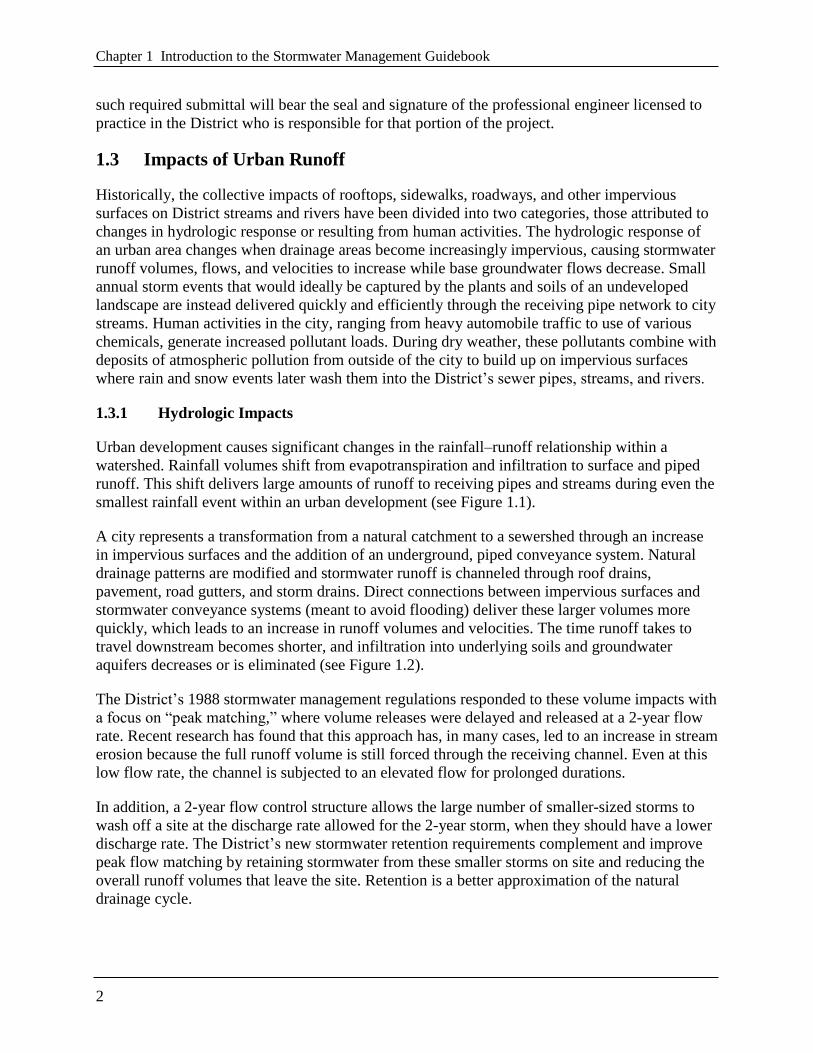
1.3 Impacts of Urban Runoff
Historically, the collective impacts of rooftops, sidewalks, roadways, and other impervious
surfaces on District streams and rivers have been divided into two categories, those attributed to
changes in hydrologic response or resulting from human activities. The hydrologic response of
an urban area changes when drainage areas become increasingly impervious, causing stormwater
runoff volumes, flows, and velocities to increase while base groundwater flows decrease. Small
annual storm events that would ideally be captured by the plants and soils of an undeveloped
landscape are instead delivered quickly and efficiently through the receiving pipe network to city
streams. Human activities in the city, ranging from heavy automobile traffic to use of various
chemicals, generate increased pollutant loads. During dry weather, these pollutants combine with
deposits of atmospheric pollution from outside of the city to build up on impervious surfaces
where rain and snow events later wash them into the District’s sewer pipes, streams, and rivers.
1.3.1 Hydrologic Impacts
Urban development causes significant changes in the rainfall–runoff relationship within a
watershed. Rainfall volumes shift from evapotranspiration and infiltration to surface and piped
runoff. This shift delivers large amounts of runoff to receiving pipes and streams during even the
smallest rainfall event within an urban development (see Figure 1.1).
A city represents a transformation from a natural catchment to a sewershed through an increase
in impervious surfaces and the addition of an underground, piped conveyance system. Natural
drainage patterns are modified and stormwater runoff is channeled through roof drains,
pavement, road gutters, and storm drains. Direct connections between impervious surfaces and
stormwater conveyance systems (meant to avoid flooding) deliver these larger volumes more
quickly, which leads to an increase in runoff volumes and velocities. The time runoff takes to
travel downstream becomes shorter, and infiltration into underlying soils and groundwater
aquifers decreases or is eliminated (see Figure 1.2).
The District’s 1988 stormwater management regulations responded to these volume impacts with
a focus on ―peak matching,‖ where volume releases were delayed and released at a 2-year flow
rate. Recent research has found that this approach has, in many cases, led to an increase in stream
erosion because the full runoff volume is still forced through the receiving channel. Even at this
low flow rate, the channel is subjected to an elevated flow for prolonged durations.
In addition, a 2-year flow control structure allows the large number of smaller-sized storms to
wash off a site at the discharge rate allowed for the 2-year storm, when they should have a lower
discharge rate. The District’s new stormwater retention requirements complement and improve
peak flow matching by retaining stormwater from these smaller storms on site and reducing the
overall runoff volumes that leave the site. Retention is a better approximation of the natural
drainage cycle.

Chapter 1 Introduction to the Stormwater Management Guidebook
3
Figure 1.1 Changes in the water balance resulting from urbanization (FISRWG, 1998).

Chapter 1 Introduction to the Stormwater Management Guidebook
4
Figure 1.2 Changes in streamflow resulting from urbanization (Schueler, 1987).
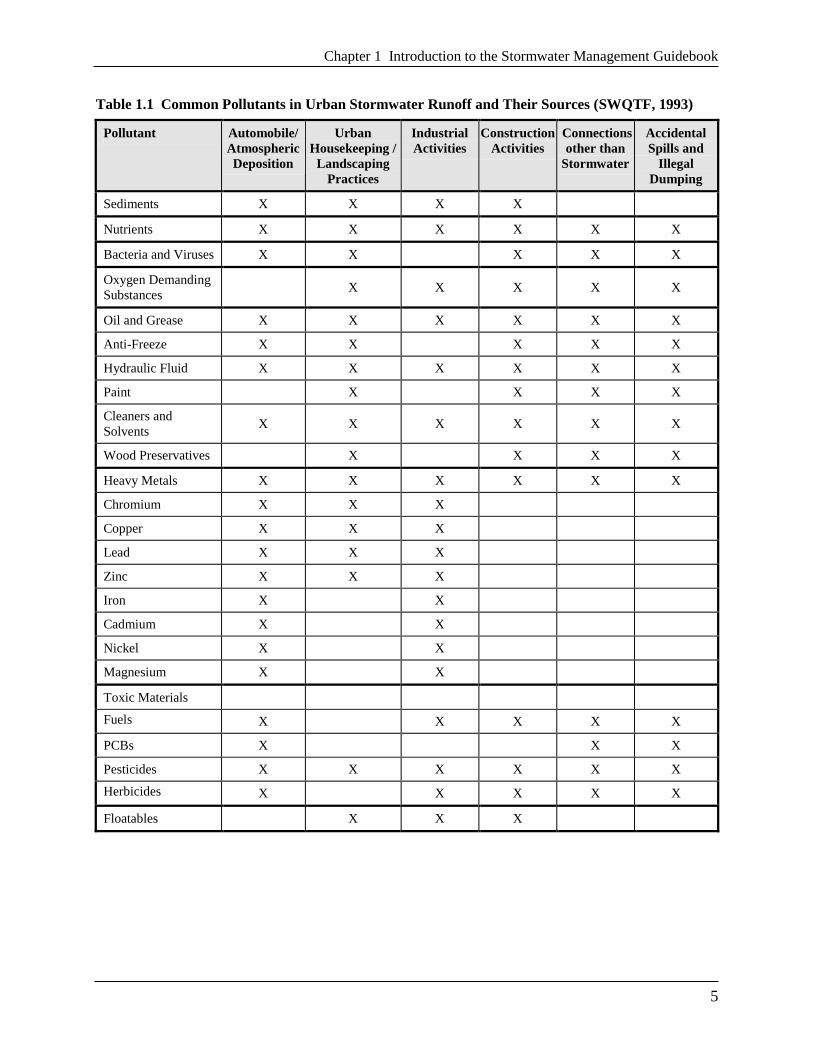
1.3.2 Water Quality Impacts
As land is developed, impervious surfaces replace naturally vegetated areas that once allowed
water to infiltrate and become purified by the soil. Approximately 43 percent of the District’s
natural groundcover has been replaced with impervious surfaces, which accumulate pollutants
deposited from the atmosphere, leaked from vehicles, or windblown from adjacent areas. During
storm events, these pollutants quickly wash off impervious surfaces and are delivered rapidly to
downstream waters. Table 1.1 profiles common pollutants found in urban stormwater runoff and
their sources.
Chapter 1 Introduction to the Stormwater Management Guidebook
5
Table 1.1 Common Pollutants in Urban Stormwater Runoff and Their Sources (SWQTF, 1993) Pollutant
Automobile/
Atmospheric
Deposition
Urban
Housekeeping /
Landscaping
Practices
Industrial
Activities
Construction
Activities
Connections
other than
Stormwater
Accidental
Spills and
Illegal
Dumping Sediments
X
X
X
X
Nutrients
X
X
X
X
X
X
Bacteria and Viruses
X
X
X
X
X
Oxygen Demanding
Substances
X
X
X
X
X
Oil and Grease
X
X
X
X
X
X
Anti-Freeze
X
X
X
X
X
Hydraulic Fluid
X
X
X
X
X
X
Paint
X
X
X
X
Cleaners and
Solvents
X
X
X
X
X
X
Wood Preservatives
X
X
X
X
Heavy Metals
X
X
X
X
X
X
Chromium
X
X
X
Copper
X
X
X
Lead
X
X
X
Zinc
X
X
X
Iron
X
X
Cadmium
X
X
Nickel
X
X
Magnesium
X
X
Toxic Materials
Fuels
X
X
X
X
X
PCBs
X
X
X
Pesticides
X
X
X
X
X
X
Herbicides
X
X
X
X
X
Floatables
X
X
X
Chapter 1 Introduction to the Stormwater Management Guidebook
6
1.4 References
Bannerman, R., D. Owens, R. Dodds, and N. Hornewer. 1993. Sources of Pollutants in
Wisconsin Stormwater. Water Science and Technology. 28(3-5):241-259.
California Stormwater Quality Taskforce (SWQTF). 1993. California Stormwater Best Practices
Handbook.
The Federal Interagency Stream Restoration Working Group (FISRWG).1998. Stream Corridor
Restoration: Principles, Processes, and Practices. GPO Item No. 0120-A; SuDocs No. A
57.6/2:EN 3/PT.653. ISBN-0-934213-59-3
Schueler, Thomas R. 1987. Controlling Urban Runoff: A Practice Manual for Planning and
Designing Urban BMPs. Department of Environmental Programs. Metropolitan Washington
Council of Governments. Prepared for: Washington Metropolitan Water Resources Planning
Board. Washington, DC.
U.S. Environmental Protection Agency. 1983. Results of the Nationwide Urban Runoff Program.
Volume I. Final Report. U.S. Environmental Protection Agency, Water Planning Division.
Washington, DC.
Waschbusch et al. 2000. Sources of phosphorus in stormwater and street dirt from two urban
residential basins in Madison, Wisconsin, 1994-1995. In: National Conference on Tools for
Urban Water Resource Management and Protection. US EPA February 2000: pp. 15-55.

7
Chapter 2 Minimum Control Requirements
2.1 District of Columbia Stormwater Management Performance
Requirements
This chapter presents a unified approach for sizing stormwater best management practices
(BMPs) in the District of Columbia (District) to meet pollutant removal goals, reduce peak
discharges, and pass extreme floods. Table 2.1 presents a summary of the sizing criteria used to
achieve the stormwater management performance requirements for regulated activity.
Those portions of regulated activity that involve the reconstruction of the existing public right-
of-way are governed by a ―maximum extent practicable‖ approach, detailed in Appendix B.
There are notes throughout this chapter that identify special conditions for regulated activity
located in the Anacostia Waterfront Development Zone (AWDZ) that are governed by the
Anacostia Waterfront Environmental Standards Amendment Act of 2012 (see D.C. Official Code
§§ 2-1226.36(c)(1)). Figure 2.1 provides a map that outlines the boundaries of the AWDZ and
the exact boundaries are provided in definitions found in Appendix U.
This chapter describes the seven sizing criteria in detail and provides guidance on how to
properly compute and manage the required volumes. This chapter also presents an overview of
acceptable BMP options that can be used to comply with the sizing criteria. Appendix A
provides a line-by-line review of the accompanying calculator spreadsheets.
Note: 2-year post-development peak discharge requirements do not apply to projects when three
conditions can be established: (1) site discharges flow directly to, or through the separate sewer
system, into the main stem of the tidal Potomac or Anacostia Rivers, the Washington Channel, or
the Chesapeake and Ohio Canal; (2) site discharges do not flow into or through a tributary to
those waterbodies that runs above ground or that the District Department of the Environment
(DDOE) expects to be daylighted to run above ground; and (3) site discharges will not cause
erosion of land or transport of sediment.

Chapter 2 Minimum Control Requirements
8
Table 2.1 Sizing Criteria for Stormwater Management Performance Requirements Sizing Criteria
Description of Stormwater Sizing Criteria
Stormwater Retention
Volume
(SWRv) (gal)
SWRv = [P × [(RvI × %I) + (RvC × %C) + (RvN × %N)] × SA] × 7.48/12
where:
SWRv = volume required to be retained on site (gal)
P = variable percentile rainfall event for the District dependent on
regulatory trigger (see next criterion)
RvI = 0.95 (runoff coefficient for impervious cover)
RvC = 0.25 (runoff coefficient for compacted cover)
RvN = 0.00 (runoff coefficient for natural cover)
%I = percent of site in impervious cover (decimal)
%C = percent of site in compacted cover (decimal)
%N = percent of site in natural cover (decimal)
SA = surface area (ft2)
7.48 = conversion factor, converting cubic feet to gallons
12 = conversion factor, converting inches to feet Precipitation value
selected based on
Regulatory Trigger (P)
Major Land-Disturbing Activity (AWDZ and District-wide): 90th percentile event
(1.2 inches)
Major Substantial Improvement Activity (AWDZ): 85th percentile event (1.0 inches)
Major Substantial Improvement Activity (District-wide): 80th percentile event (0.8
inches)
Reconstruction of public
right-of-way
Consult Appendix B
Maximum Extent Practicable Process for Existing Public Right-of-Way
Water Quality Treatment
Volume (WQTv) (gal)
(applies only to regulated
activity in the AWDZ
area governed by the
Anacostia Waterfront
Environmental Standards
Amendment Act of 2012)
WQTv = (P × [(RvI × %I) + (RvC × %C) + (RvN × %N) × SA] × 7.48/12) - SWRv
where:
WQTv = volume required to be retained or treated, above and beyond the
SWRv (gal)
SWRv = volume required to be retained on site (gal)
P = 95th percentile rain event for the District (1.7 inches)
RvI = 0.95 (runoff coefficient for impervious cover)
RvC = 0.25 (runoff coefficient for compacted cover)
RvN = 0.00 (runoff coefficient for natural cover)
%I = percent of site in impervious cover (decimal)
%C = percent of site in compacted cover (decimal)
%N = percent of site in natural cover (decimal)
SA = surface area (ft2)
7.48 = conversion factor, converting cubic feet to gallons
12 = conversion factor, converting inches to feet 2-Year Storm Control
(Qp2)
The peak discharge rate from the 2-year, 24-hour storm event controlled to the
predevelopment peak discharge rate. 15-Year Storm Control
(Qp15)
The peak discharge rate from the 15-year, 24-hour storm event controlled to the
preproject peak discharge rate.
Extreme Flood
Requirements (Qf)
The peak discharge rate from the 100-year storm event controlled to the preproject
peak discharge rate if the site:
1) Increases the size of a Special Flood Hazard Area (SFHA) as delineated on the
effective Flood Insurance Rate Maps (FIRM) or
2) Meets the following two conditions:
(a) Does not discharge to the sewer system and
(b) Has a post-development peak discharge rate for a 100-year frequency storm
event that will cause flooding to a building.

Chapter 2 Minimum Control Requirements
9
Figure 2.1 Map of Anacostia Waterfront Development Zone.
2.2 Stormwater Retention Volume
Regulated sites that undergo a major land-disturbing activity or a major substantial improvement
activity must employ BMPs and post-development land cover necessary to achieve the
stormwater retention volume (SWRv) equal to the post-development runoff from the applicable
rainfall event, as measured for a 24-hour storm with a 72-hour antecedent dry period. For a major
substantial improvement activity located in the AWDZ, governed by the Anacostia Waterfront
Environmental Standards Amendment Act of 2012, the applicable rainfall event is the 85th
percentile rainfall event (1.0 inches). For all other major substantial improvement activities
throughout the District, the applicable rainfall event is the 80th percentile rainfall event (0.8
inches). The SWRv is calculated as follows for the entire site and for each drainage area:

Chapter 2 Minimum Control Requirements
10
Equation 2.1 Stormwater Retention Volume
12
48.7%+%+%
SANRvCRvIRvPSWRv NCI
where:
SWRv = volume required to be retained on site (gal)
P = selection of District rainfall event varies based on regulatory trigger; 90th
percentile (1.2 inches) for major land-disturbing activity, 85th percentile (1.0
inches) for major substantial improvement activity in the AWDZ and
governed by the Anacostia Waterfront Environmental Standards Amendment
Act of 2012, 80th percentile (0.8 inches) for other major substantial
improvement activities
RvI = runoff coefficient for impervious cover (0.95)
%I = percent of site in impervious cover
RvC = runoff coefficient for compacted cover (0.25)
%C = percent of site in compacted cover
RvN = runoff coefficient for natural cover (0.00)
%N = percent of site in natural cover
SA = surface area (ft2)
7.48 = conversion factor, converting cubic feet to gallons
12 = conversion factor, converting inches to feet
where the surface area under a BMP shall be calculated as part of the impervious cover (%I); and
A site may achieve on-site retention by directly conveying volume from the regulated site to a
shared BMP with available retention capacity. A site may achieve the SWRv on site or through a
combination of on-site retention and off-site retention under the following conditions:
The site shall retain on site a minimum of 50 percent of the SWRv calculated for the entire
site, unless DDOE approves an application for relief from extraordinarily difficult site
conditions (Appendix E).
The site shall use off-site retention for the portion of the SWRv that is not retained on site
(See Chapter 6 and Appendix C).
Regulated activity in the AWDZ, governed by the Anacostia Waterfront Environmental
Standards Amendment Act of 2012, must have all off-site retention approved by DDOE even
if the minimum 50 percent on-site requirement has been achieved. These projects may apply
to achieve retention compliance with off-site retention based on considerations of technical
infeasibility and environmental harm as well as the limited appropriateness of on-site
compliance in terms of impact on surrounding landowners or overall benefit to District
waterbodies.
Projects requesting relief from compliance with the minimum on-site retention obligation
(50% of the SWRv) and claiming ―extraordinarily difficult site conditions‖ will follow the
submission and evaluation process detailed in Appendix E. Sites approved for ―relief from

Chapter 2 Minimum Control Requirements
11
extraordinarily difficult site conditions‖ are still responsible for the entire SWRv but will be
allowed to use off-site retention to achieve more than 50percent of the SWRv.
An individual drainage area is defined as the area that drains to a single discharge point from the
site. A site may achieve on-site retention by retaining more than the SWRv in an individual
drainage area, subject to the following conditions:
For each drainage area, as well as for all vehicular access areas within each drainage area, at
least 50 percent of the SWRv must be retained or treated with an accepted practice to remove
80 percent of total suspended solids (TSS), unless it drains into the combined sewer system.
For vehicular access areas that are part of a submission following the maximum extent
practicable (MEP) process, the MEP narrative must address the placement and sizing
opportunities and the restrictions of a retention practice where these minimums are not
achieved. Figure 2.2 provides a map that outlines the boundaries of the District’s Combined
Sewer System (CSS) and Municipal Separate Storm Sewer System (MS4).
Retention in excess of the SWRv for one drainage area may be applied to the retention
volume required for another drainage area;
Retention of volume greater than that from a 1.7-inch rainfall event, calculated using the
SWRv equation with a P equal to 1.7 inches, shall not be counted toward on-site retention.

Chapter 2 Minimum Control Requirements
12
Figure 2.2 Map of District of Columbia MS4 and CSS areas.

Chapter 2 Minimum Control Requirements
13
The following are ―Accepted Practices‖ by DDOE for treatment to remove 80 percent of TSS:
Permeable Pavement Systems
Bioretention
Stormwater Filtering Systems
Stormwater Ponds
Wetlands
Dry Swales
Wet Swales
Proprietary practices that have been demonstrated to achieve an 80 percent reduction in TSS
in accordance with the requirements of Appendix S.
Major land-disturbing activities in the existing public right-of-way, including activities
associated with a major land-disturbing activity on private property, must achieve the SWRv to
the MEP. The MEP design and review process is detailed in Appendix B.
2.3 Water Quality Treatment Volume
In addition to the SWRv requirements above, sites located in the AWDZ and governed by the
Anacostia Waterfront Environmental Standards Amendment Act of 2012 shall employ BMPs
and post-development land cover necessary to achieve a water quality treatment volume (WQTv)
equal to the difference between the post-development runoff from the 95th percentile rainfall
event (1.7 inches), measured for a 24-hour rainfall event with a 72-hour antecedent dry period,
and the SWRv. The WQTv is calculated as follows, for the entire site, and each individual
drainage area:
Equation 2.2 Water Quality Treatment Volume
SWRvSANRvCRvIRvPWQTv NCI 48.7%+%+%
where:
WQTv = volume, in gallons, required to be retained or treated, above and beyond the
Stormwater Retention Volume (SWRv).
SWRv = volume, in gallons, required to be retained, as described in Section 2.2
P = 95th percentile rainfall event for the District (1.7 inches)
RvI = 0.95 (runoff coefficient for impervious cover)
RvC = 0.25 (runoff coefficient for compacted cover)
RvN = 0.00 (runoff coefficient for natural cover)
%I = percent of site in impervious cover
%C = percent of site in compacted cover
%N = percent of site in natural cover
SA = surface area in square feet,

Chapter 2 Minimum Control Requirements
14
where, the surface area under a BMP shall be calculated as part of the impervious cover (%I);
and
A site in the AWDZ that is governed by the Anacostia Waterfront Environmental Standards
Amendment Act of 2012 may achieve on-site treatment for WQTv with:
On-site treatment with an accepted treatment practice designed to remove 80 percent of TSS;
On-site retention; or
Direct conveyance of stormwater from the site to an approved shared BMP with sufficient
available treatment or retention capacity.
An AWDZ site that is governed by the Anacostia Waterfront Environmental Standards
Amendment Act of 2012 may achieve part of the WQTv by using off-site retention if site
conditions make compliance technically infeasible or environmentally harmful and DDOE
approves an application for ―relief from extraordinarily difficult site conditions.‖
An AWDZ site governed by the Anacostia Waterfront Environmental Standards Amendment Act
of 2012 that achieves 1 gallon of off-Site retention volume (Offv) by using Stormwater Retention
Credits (SRCs) certified for retention capacity located outside of the Anacostia watershed shall
use 1.25 SRCs for that gallon of Offv.
Figures 2.3–2.7 describe the relationship between a variety of project types, the SWRv, and the
WQTv.
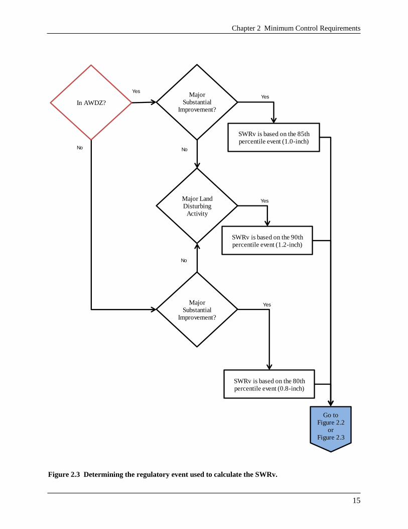
Chapter 2 Minimum Control Requirements
15
Figure 2.3 Determining the regulatory event used to calculate the SWRv.
Yes
Yes
No
Yes
No
In AWDZ?
Major Substantial
Improvement?
Major Substantial
Improvement?
No
Major Land Disturbing
Activity
SWRv is based on the 85th percentile event (1.0-inch)
Yes
SWRv is based on the 90th percentile event (1.2-inch)
SWRv is based on the 80th percentile event (0.8-inch)
Go to Figure 2.2
or Figure 2.3

Chapter 2 Minimum Control Requirements
16
Figure 2.4 Determining if overall retention requirements have been met, outside the AWDZ.
Yes
100%
SWRvretained
on-site?
No
Yes Overall Requirements met.
Go to Figure 2.4 to check minimum requirements.
No
Yes
Yes
No
SWRv calculated,
project not in the
AWDZ.
50%
SWRvretained
on-site?
Use off-site
retention for the
balance.
Yes
OptionalExceed the
SWRvfor SRCs.
DDOE provide
"relief for extraordinarily
difficult site conditions".

Chapter 2 Minimum Control Requirements
17
Figure 2.5 Determining if overall retention and water quality treatment requirements have been
met, inside the AWDZ for regulated activity governed by the Anacostia Waterfront Environmental
Standards Amendment Act of 2012.
SWRvcalculated,
project is in the AWDZ.
100%
SWRvretained
on-site?
No
DDOE
provide"relief for
extraordinarilydifficult site conditions".
No
Yes
100%
WQTvretained or
treatedon-site?
YesOverall Requirements
met. Go to Figure 2.4 to check minimum
Yes
No
Yes
Use off-site
retention for the SWRv
balance.
Use off-site
retention for the WQTv
balance.
Yes
DDOE
provide"relief for
extraordinarilydifficult site conditions".
Yes
Yes
No

Chapter 2 Minimum Control Requirements
18
Figure 2.6 Determining if minimum retention and water quality treatment requirements have been
met.
Yes
No
Yes
NoIn CSS?
Are there Vehicular
Access Area(s) within the site?
Treat or Retain 50% of SWRv for each drainage area within the
limits of disturbance.
Retain 50% of SWRv for entire
site. No treatment required.
No
Treat or Retain 50% of SWRv flowing from entire
vehicular area.*
* Existing Public right-of-way (PROW) sites follow these guidelines to the maximum
extent practicable (MEP). The MEP design and review process is detailed in Appendix B.
Overall SWRv and WQTv
requirements met on-site, or with a
combination of on-site and
off-site approaches.
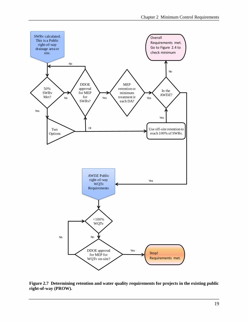
Chapter 2 Minimum Control Requirements
19
Figure 2.7 Determining retention and water quality requirements for projects in the existing public
right-of-way (PROW).
Yes
No
Yes
No
Yes
No
No
Yes
No
50% SWRv Met?
DDOE approval for MEP
for SWRv?
Overall
Requirements met.Go to Figure 2.4 to
check minimum
Use off-site retention to reach 100% of SWRv.
Two Options
Yes
SWRv calculated. This is a Public
right-of-way drainage area or
site.
<100% WQTv
DDOE approval for MEP for
WQTv on-site?
In the AWDZ?
AWDZ Public right-of-way
WQTv Requirements
Stop!
Requirements met.
Yes
MEP retention or minimum
treatment in each DA?
Yes
Or

Chapter 2 Minimum Control Requirements
20
2.4 Extreme Flood Requirements
To meet the extreme flood requirements (Qf), a site shall maintain the peak discharge rate from
the 100-year storm event controlled to the preproject peak discharge rate if the site:
1. Increases the size of a Special Flood Hazard Area (SFHA) as delineated on the effective
Flood Insurance Rate Maps (FIRM) or
2. Meets the following two conditions:
(a) Does not discharge to the sewer system and
(b) Has a post-development peak discharge rate for a 100-year-frequency storm event that
will cause flooding to a building.
The intent of the extreme flood criteria is to (a) prevent flood damage from large storm events,
and (b) maintain the boundaries of the 100-year Federal Emergency Management Agency
(FEMA) floodplain.
In general, stormwater runoff leaving a development site shall be discharged directly into an
adequate natural or man-made receiving channel, pipe, or storm sewer system, or the applicant
shall provide a drainage system satisfactory to DDOE to preclude an adverse impact (e.g., soil
erosion, sedimentation, flooding, duration of ponding water, inadequate overland relief) on
downstream properties and receiving systems. If the applicant chooses to install a drainage
system, the system shall be designed in accordance with established, applicable criteria for such
systems.
Stormwater runoff leaving a development site where it does not discharge directly to the sewer
system shall not aggravate or create a condition where an existing building is flooded from the
100-year storm event. If such a condition exists, on-site detention for the 100-year storm event
shall be provided.
In situations where the size of the Special Flood Hazard Area (SFHA) as delineated on the
effective Flood Insurance Rate Map (FIRM) by the Federal Emergency Management Agency
(FEMA) will be increased based on the increased post-development 100-year discharge, the
post-development 100-year peak discharge shall be maintained at a level that is equal to or less
than the preproject 100-year peak discharge.
2.5 Minimum Criteria for Determining Extreme Flood Requirements
It is recommended that an applicant use the District’s online Flood Zone Determination Tool
(available at http://ddoe.dc.gov/floodplainmap) as an initial screening for this section.
An applicant shall use the following minimum criteria to determine whether extreme flood
requirements are applicable:

Chapter 2 Minimum Control Requirements
21
Downstream Analysis:
1. Consult DDOE to initially determine whether or not the downstream analysis is needed. A
site visit is necessary for the determination. This analysis is used to determine the impact of
the 100-year post-development discharge on a building.
2. If the analysis is needed, the analysis shall contain supporting computations as justification
for the conclusions contained in the analysis. For consistency, the following items are to be
included, at a minimum:
(a) Site-specific narrative with a description of the elements of the storm drainage system,
overland relief paths and adjoining properties;
(b) A drainage plan showing outfall location(s) with the contributing drainage areas for each
outfall. Digital pictures of the outfall shall be included;
(c) A profile for each outfall channel and overland relief path;
(d) Two cross sections, at a minimum, at each critical location to verify the outfall and
overland relief adequacy. Cross sections shall be based on a 2-foot contour interval and
additional spot elevations in the vicinity. The cross sections shall have the same vertical
and horizontal scales and shall identify the top of banks for the channel;
(e) Description of the outfall channel and permissible velocity. The Manning’s roughness
coefficient shall be supported by soil classification, cover material, and channel’s or flow
path’s lining. The description of physical characteristics may include the amount of flow
meandering, material classification of the flow path and its banks, vegetation, obstruction
to flow, variations in cross sections and surface irregularity;
(f) Detailed hydrologic and hydraulic (H & H) calculations to obtain the 100-year water
surface elevation (WSE). The acceptable methodologies and models are specified in
Appendix H;
(g) Delineation of the 100-year WSE on the project drainage plan to show the location and
approximate extent of the overland relief path and areas that may be affected by the
surface storage for the 100-year storm event. Overlaying arrows, shading or other suitable
see-through graphics are suggested for this purpose; and
(h) Certification by the District professional engineer that no buildings will be subject to
increased flooding by the 100-year post-development discharge from the development
site.
3. If buildings will be flooded based on the analysis, then the design engineer must perform
more precise hydrologic and hydraulic computations. In addition to the on-site 100-year
detention, the applicant shall design the outfall drainage system, overland relief swales,
and/or surface storage in such a way that no building will be damaged by flooding.
4. If the protection measures for the outfall drainage system or overland relief path are
provided, necessary design details shall be shown and supported by calculations and
submitted to DDOE for review.
Chapter 2 Minimum Control Requirements
22
Hydrologic and Hydraulic Analysis:
1. Consult DDOE to initially determine whether or not the H&H analysis is needed. This
analysis is used to determine the impact on SFHA by considering the entire watershed.
2. The acceptable methodologies and models for H&H analysis are specified in Section 2.7 and
further described in Appendix H.
3. H&H investigations may be required to demonstrate that downstream roads, bridges, and
public utilities are adequately protected from the Qf storm. These investigations typically
extend to the first downstream tributary of equal or greater drainage area or to any
downstream dam, highway, or natural point of restricted stream flow.
2.6 Additional Stormwater Management Requirements
Any BMP that may receive stormwater runoff from areas that are potential sources of oil and
grease contamination (concentrations exceeding 10 milligrams per liter) shall include a baffle,
skimmer, oil separator, grease trap, or other mechanism that prevents oil and grease from
escaping the BMP in concentrations exceeding 10 milligrams per liter.
Any BMP that receives stormwater runoff from areas used to confine animals may be required
connect to a sanitary or combined sewer and to meet DC Water’s pretreatment requirements.
2.7 Hydrology Methods
The following are the acceptable methodologies and computer models for estimating runoff
hydrographs before and after development. These methods are used to predict the runoff
response from given rainfall information and site surface characteristic conditions. The design
storm frequencies used in all of the hydrologic engineering calculations will be based on design
storms required in this guidebook unless circumstances make consideration of another storm
intensity criteria appropriate.
Urban Hydrology for Small Watersheds TR-55
Storage-Indication Routing
HEC-HMS, WinTR-55, TR-20, and SWMM Computer Models
Rational Method (limited to sites under 5 acres)
These methods are given as valid in principle, and are applicable to most stormwater
management design situations in the District. Other methods may be used when the District
reviewing authority approves their application.
The use of the Natural Resource Conservation Service’s (NRCS’s) Storage Indication Routing
method or an equivalent acceptable method may be required to route the design storms through
stormwater facilities. A modified version of the NRCS Curve Number method is provided for
computing the peak discharge for the SWRv 1.2-inch rain event. See Appendix H for further
details and guidance on both computation procedures.

Chapter 2 Minimum Control Requirements
23
2.8 Acceptable Urban BMP Options
This section sets forth 13 acceptable groups of BMPs that can be used to meet the SWRv and/or
peak flow (Qp2, Qp15, Qf) criteria.
The dozens of different BMP designs currently used in the District are assigned to 13 general
categories for stormwater quality control:
BMP Group 1 Green Roofs
BMP Group 2 Rainwater Harvesting
BMP Group 3 Impervious Surface Disconnection
BMP Group 4 Permeable Pavement Systems
BMP Group 5 Bioretention
BMP Group 6 Filtering Systems
BMP Group 7 Infiltration
BMP Group 8 Open Channel Systems
BMP Group 9 Ponds
BMP Group 10 Wetlands
BMP Group 11 Storage Practices
BMP Group 12 Proprietary Practices
BMP Group 13 Tree Planting and Preservation
Within each BMP group, detailed performance criteria are presented that govern feasibility,
conveyance, pretreatment, treatment, landscaping, construction sequence, maintenance, and
stormwater retention calculations (see Chapter 3).
Guidance on selecting the most appropriate combination of BMPs is provided in Chapter 4.
BMP Group 1 Green Roofs
Green roofs are BMPs that capture and store rainfall, which would otherwise land on an
impervious rooftop, in an engineered growing media that is designed to support plant growth. A
portion of the captured rainfall evaporates or is taken up by plants, which helps reduce runoff
volumes, peak runoff rates, and pollutant loads. Design variants include:
G-1 Extensive green roofs have a much shallower growing media layer that typically ranges
from 3 to 6 inches thick.
G-2 Intensive green roofs have a growing media layer that ranges from 6 inches to 4 feet
thick.

Chapter 2 Minimum Control Requirements
24
BMP Group 2 Rainwater Harvesting
Rain water harvesting systems intercept, divert, store, and release rainfall for future use.
Rainwater that falls on a rooftop is collected and conveyed into an above- or below-ground
storage tank (also referred to as a cistern or rain tank), where it can be used for non-potable water
uses and on-site stormwater disposal/infiltration.
BMP Group 3 Impervious Surface Disconnection
This strategy involves managing runoff close to its source by intercepting, infiltrating, filtering,
treating, or reusing it as it moves from the impervious surface to the drainage system. Simple
disconnection variants include:
D-1 Simple disconnection to a pervious compacted cover area
D-2 Simple disconnection to a conserved natural cover area
D-3 Simple disconnection to a soil compost amended filter path
Disconnection can also be employed as part of infiltration, bioretention, and rainwater harvesting
systems.
BMP Group 4 Permeable Pavement Systems
Permeable pavement is an alternative paving surface that captures and temporarily stores the
design volume by filtering runoff through voids in the pavement surface into an underlying stone
reservoir. Filtered runoff may be collected and returned to the conveyance system, or allowed to
partially infiltrate into the soil. Design variants include:
P-1 Porous asphalt (PA)
P-2 Pervious concrete (PC)
P-3 Permeable pavers (PP)
BMP Group 5 Bioretention
Bioretention facilities are BMPs that capture and store stormwater runoff and pass it through a
filter bed of engineered soil media comosed of sand, soil, and organic matter. Filtered runoff may
be collected and returned to the conveyance system, or allowed to infiltrate into the soil. Design
variants include:
B-1 Traditional bioretention
B-2 Streetscape bioretention
B-3 Engineered tree pits
B-4 Stormwater planters
B-5 Residential rain gardens

Chapter 2 Minimum Control Requirements
25
BMP Group 6 Filtering Systems
Filtering systems are BMPs that capture and temporarily store the design volume and pass it
through a filter bed of sand, organic matter, soil or other filtering media. Filtered runoff may be
collected and returned to the conveyance system. Design variants include:
F-1 Non-structural sand filter
F-2 Surface sand filter
F-3 Three-chamber underground sand filter
F-4 Perimeter sand filter
BMP Group 7 Infiltration BMPs
Infiltration BMPs capture and store the design volume before allowing it to infiltrate into the soil
over a 48-hour period. Design variants include:
I-1 Infiltration trench
I-2 Infiltration basin
BMP Group 8 Open Channel BMPs
Open channel BMPs are vegetated open channels that are designed to capture and treat or convey
the design storm volume. Design variants include:
O-1 Grass channels
O-2 Dry swale
O-3 Wet swale
BMP Group 9 Ponds
Stormwater ponds are stormwater storage BMPs that consist of a combination of a permanent
pool, micropool, or shallow marsh that promote a good environment for gravitational settling,
biological uptake, and microbial activity. Design variants include:
P-1 Micropool extended detention pond
P-2 Wet pond
P-3 Wet extended detention (ED) pond
BMP Group 10 Wetlands
Stormwater wetlands are BMPs that create shallow marsh areas to treat urban stormwater which
often incorporate small permanent pools and/or extended detention storage. Stormwater wetlands
are explicitly designed to provide stormwater detention for larger storms (2-year, 15-year or
flood control events) above the SWRv. Design variants include:

Chapter 2 Minimum Control Requirements
26
W-1 Shallow wetland
W-2 Extended detention (ED) shallow wetland
BMP Group 11 Storage Practices
Storage practices are explicitly designed to provide stormwater detention (2-year, 15-year, and/or
flood control). Storage practices alone are not considered acceptable practices to meet the SWRv
or TSS removal requirements. Design variants include:
S-1 Underground vault
S-2 Dry pond
S-3 Rooftop storage
S-4 Stone storage under permeable pavement or other BMPs
Design guidance and criteria for the practice of rooftop storage is provided in Appendix I.
BMP Group 12 Proprietary Practices
Proprietary practices are manufactured stormwater BMPs that utilize settling, filtration,
absorptive/adsorptive materials, vortex separation, vegetative components, and/or other
appropriate technology to manage the impacts of stormwater runoff.
Proprietary practices may meet the SWRv value as well as the TSS removal value, provided they
have been approved by DDOE through the process detailed in Appendix S.
BMP Group 13 Tree Planting and Preservation
Trees can significantly reduce stormwater runoff by canopy interception and uptake of water
from the soil. Trees are well documented in their ability to reduce stormwater runoff, particularly
when the tree canopy covers impervious surface, such as in the case of street trees.

27
Chapter 3 Stormwater Best Management
Practices (BMPs)
3.1 Standard Best Management Practice Design Guidance Format
This chapter outlines performance criteria for 13 stormwater best management practice (BMP)
categories that include green roofs, rainwater harvesting, impermeable surface disconnection,
permeable pavement, bioretention, filtering systems, infiltration practices, storage practices,
ponds, wetlands, open channels, proprietary practices, and tree planting.
BMP performance criteria are based on several critical design factors to ensure effective and
long-lived BMPs. Design components that differ from these specifications but meet their intent
may be included at the District Department of the Environment’s (DDOE’s) discretion. In this
chapter, and throughout the guidebook, the terms ―must‖ or ―shall‖ denote required aspects of
BMPs or their design and implementation, while the term ―should‖ denotes a recommendation.
However, justification may be necessary for design or implementation that does not correspond
to certain recommendations.
For each BMP, the following factors are discussed:
General Feasibility
Conveyance
Pretreatment
Design and Sizing
Landscaping
Construction Sequencing
Maintenance
Stormwater Compliance Calculations


3.2 Green Roofs
29
3.2 Green Roofs
Definition. Practices that capture and store rainfall in an engineered growing media that is
designed to support plant growth. A portion of the captured rainfall evaporates or is taken up by
plants, which helps reduce runoff volumes, peak runoff rates, and pollutant loads on
development sites. Green roofs typically contain a layered system of roofing, which is designed
to support plant growth and retain water for plant uptake while preventing ponding on the roof
surface. The roofs are designed so that water drains vertically through the media and then
horizontally along a waterproofing layer towards the outlet. Extensive green roofs are designed
to have minimal maintenance requirements. Plant species are selected so that the roof does not
need supplemental irrigation and requires minimal, infrequent fertilization after vegetation is
initially established.
Design variants include extensive and intensive green roofs.
G-1 Extensive green roofs have a much shallower growing media layer that typically ranges
from 3 to 6 inches thick.
G-2 Intensive green roofs have a growing media layer that ranges from 6 to 48 inches thick.
Green roofs are typically not designed to provide stormwater detention of larger storms (e.g., 2-
year, 15-year) although some intensive green roof systems may be designed to meet these
criteria. Most green roof designs shall generally be combined with a separate facility to provide
large storm controls.
This specification is intended for situations where the primary design objective of the green roof
is stormwater management and, unless specified otherwise, addresses the design of extensive
roof systems. While rooftop practices such as urban agriculture may provide some retention,
their primary design objective is not stormwater management and is not addressed in this
specification.
3.2.1 Green Roof Feasibility Criteria
Green roofs are ideal for use on commercial, institutional, municipal, and multi-family
residential buildings. They are particularly well-suited for use on ultra-urban development and
redevelopment sites. Key constraints with green roofs include the following:
Structural Capacity of the Roof. When designing a green roof, designers must not only
consider the stormwater storage capacity of the green roof but also its structural capacity to
support the weight of the additional water. A conventional rooftop should typically be designed
to support an additional 15 to 30 pounds per square foot (psf) for an extensive green roof. As a
result, a structural engineer, architect, or other qualified professional should be involved with all
green roof designs to ensure that the building has enough structural capacity to support a green
roof. See Section 3.2.4 Green Roof Design Criteria for more information on structural design
considerations.
Roof Pitch. Green roof storage volume is maximized on relatively flat roofs (a pitch of 1 to 2
percent). Some pitch is needed to promote positive drainage and prevent ponding and/or

Chapter 3 Stormwater Best Management Practices (BMPs)
30
saturation of the growing media. Green roofs can be installed on rooftops with slopes up to 30
percent if baffles, grids, or strips are used to prevent slippage of the media. These baffles must be
designed to ensure the roof provides adequate storage for the design storm. Slopes greater than
30 percent would be considered a green wall, which is not specifically identified as a stormwater
best management practice (BMP). Green walls can be used to receive cistern discharge
(calculations are necessary to determine demand) and can be used to comply with Green Area
Ratio Requirements.
Roof Access. Adequate access to the roof must be available to deliver construction materials and
perform routine maintenance. Roof access can be achieved either by an interior stairway through
a penthouse or by an alternating tread device with a roof hatch or trap door not less than 16
square feet in area and with a minimum dimension of 24 inches (NVRC, 2007). Designers
should also consider how they will get construction materials up to the roof (e.g., by elevator or
crane) and how the roof structure can accommodate material stockpiles and equipment loads. If
material and equipment storage is required, rooftop storage areas must be identified and clearly
marked based on structural load capacity of the roof.
Roof Type. Green roofs can be applied to most roof surfaces. Certain roof materials, such as
exposed treated wood and uncoated galvanized metal, may not be appropriate for green rooftops
due to pollutant leaching through the media (Clark et al, 2008).
Setbacks. Green roofs should not be located near rooftop electrical and HVAC systems. A 2-foot
wide vegetation-free zone is recommended along the perimeter of the roof with a 1-foot
vegetation-free zone around all roof penetrations, to act as a firebreak. The 2-foot setback may
be relaxed for small or low green roof applications where parapets have been properly designed.
Contributing Drainage Area. It is recommended that the entire contributing drainage area to a
green roof (including the green roof itself) be no more than 25 percent larger than the area of the
green roof. In cases where the area exceeds this threshold, the designer must provide supporting
documentation of rooftop loading, sufficient design to distribute runoff throughout the green roof
and prevent erosion of the roof surface, and justification for incorporating a sizable external
drainage area to the green roof.
District Building Codes. The green roof design must comply with the District’s building codes
with respect to roof drains and emergency overflow devices. Additionally, a District of Columbia
registered structural engineer must certify that the design complies with District Building
structural codes. This is true for new construction as well as retrofit projects.
3.2.2 Green Roof Conveyance Criteria
The green roof drainage layer (refer to Section 3.2.4) must convey flow from under the growing
media directly to an outlet or overflow system such as a traditional rooftop downspout drainage
system. The green roof drainage layer must be adequate to convey the volume of stormwater
equal to the flow capacity of the overflow or downspout system without backing water up onto
the rooftop or into the green roof media. Roof drains immediately adjacent to the growing media
should be boxed and protected by flashing extending at least 3 inches above the growing media
to prevent clogging. However, an adequate number of roof drains that are not immediately

3.2 Green Roofs
31
adjacent to the growing media must be provided so as to allow the roof to drain without 3 inches
of ponding above the growing media.
3.2.3 Green Roof Pretreatment Criteria
Pretreatment is not necessary for green roofs.
3.2.4 Green Roof Design Criteria
Structural Capacity of the Roof. Green roofs can be limited by the additional weight of the
fully saturated soil and plants, in terms of the physical capacity of the roof to bear structural
loads. The designer shall consult with a licensed structural engineer to ensure that the building
will be able to support the additional live and dead structural load and to determine the maximum
depth of the green roof system and any needed structural reinforcement. Typically, the green roof
manufacturer can provide specific background specifications and information on their product
for planning and design.
In most cases, fully saturated extensive green roofs have loads of about 15 to 30 pounds per
square foot, which is fairly similar to traditional new rooftops (12 to 15 pounds per square foot)
that have a waterproofing layer anchored with stone ballast. For a discussion of green roof
structural design issues, consult Chapter 9 in Weiler and Scholz-Barth (2009) and ASTM E-
2397, Standard Practice for Determination of Dead Loads and Live Loads Associated with
Vegetative (Green) Roof Systems.
Functional Elements of a Green Roof System. A green roof is composed of up to nine
different systems or layers that combine to protect the roof and maintain a vigorous cover (see
Figure 3.1).
Figure 3.1 Typical layers for a green roof. Note: the relative placement of various layers may vary
depending on the type and design of the green roof system.

Chapter 3 Stormwater Best Management Practices (BMPs)
32
The design layers include the following:
1. Deck Layer. The roof deck layer is the foundation of a green roof. It may be composed of
concrete, wood, metal, plastic, gypsum, or a composite material. The type of deck material
determines the strength, load bearing capacity, longevity, and potential need for insulation in
the green roof system.
2. Leak Detection System (optional). Leak detection systems are often installed above the
deck layer to identify leaks, minimize leak damage through timely detection, and locate leak
locations.
3. Waterproofing Layer. All green roof systems must include an effective and reliable
waterproofing layer to prevent water damage through the deck layer. A wide range of
waterproofing materials can be used, including hot applied rubberized asphalt, built up
bitumen, modified bitumen, thermoplastic membranes, polyvinyl chloride (PVC),
thermoplastic olefin membrane (TPO), and elastomeric membranes (EPDM) (see Weiler and
Scholz-Barth, 2009, and Snodgrass and Snodgrass, 2006). The waterproofing layer must be
100 percent waterproof and have an expected life span as long as any other element of the
green roof system. The waterproofing material may be loose laid or bonded (recommended).
If loose laid, overlapping and additional construction techniques should be used to avoid
water migration.
4. Insulation Layer. Many green rooftops contain an insulation layer, usually located above,
but sometimes below, the waterproofing layer. The insulation increases the energy efficiency
of the building and/or protects the roof deck (particularly for metal roofs). According to
Snodgrass and Snodgrass (2006), the trend is to install insulation on the outside of the
building, in part to avoid mildew problems. The designer should consider the use of open or
closed cell insulation depending on whether the insulation layer is above or below the
waterproofing layer (and thus exposed to wetness), with closed cell insulation recommended
for use above the waterproofing layer.
5. Root Barrier. Another layer of a green roof system, which can be either above or below the
insulation layer depending on the system, is a root barrier that protects the waterproofing
membrane from root penetration. A wide range of root barrier options are described in
Weiler and Scholz-Barth (2009). Chemical root barriers or physical root barriers which have
been impregnated with pesticides, metals, or other chemicals that could leach into stormwater
runoff, must be avoided in systems where the root barrier layer will come in contact with
water or allow water to pass through the barrier.
6. Drainage Layer and Drainage System. A drainage layer is then placed between the root
barrier and the growing media to quickly remove excess water from the vegetation root zone.
The selection and thickness of the drainage layer type is an important design decision that is
governed by the desired stormwater storage capacity, the required conveyance capacity, and
the structural capacity of the rooftop. The effective depth of the drainage layer is generally
0.25 to 1.5 inches thick for extensive green roof system and increases for intensive designs.
The drainage layer should consist of synthetic or inorganic materials (e.g., 1-2 inch layer of
clean, washed granular material (ASTM D448 size No. 8 stone or lightweight granular mix),
high density polyethylene (HDPE)) that are capable of retaining water and providing efficient
drainage. A wide range of prefabricated water cups or plastic modules can be used, as well as

3.2 Green Roofs
33
a traditional system of protected roof drains, conductors, and roof leaders. ASTM E2396 and
E2398 can be used to evaluate alternative material specifications.
7. Root-Permeable Filter Fabric. A semi-permeable needled polypropylene filter fabric is
normally placed between the drainage layer and the growing media to prevent the media
from migrating into the drainage layer and clogging it. The filter fabric must not impede the
downward migration of water into the drainage layer.
8. Growing Media. The next layer in an extensive green roof is the growing media, which is
typically 3 to 6 inches deep (minimum 3 inches). The recommended growing media for
extensive green roofs is typically composed of approximately 70 to 80 percent lightweight
inorganic materials, such as expanded slates, shales or clays; pumice; scoria; or other similar
materials. The remaining media must contain no more than 30 percent organic matter,
normally well-aged compost (see Appendix J). The percentage of organic matter should be
limited, since it can leach nutrients into the runoff from the roof and clog the permeable filter
fabric. The growing media typically has a maximum water retention of approximately 30
percent. Proof of growing media maximum water retention must be provided by the
manufacturer. It is advisable to mix the media in a batch facility prior to delivery to the roof.
As there are many different types of proprietary growing medias and roof systems, the values
provided here are recommendations only. Manufacturer’s specifications should be followed
for all proprietary roof systems. More information on growing media can be found in Weiler
and Scholz-Barth (2009) and Snodgrass and Snodgrass (2006).
The composition of growing media for intensive green roofs may be different, and it is often
much greater in depth (e.g., 6 to 48 inches). If trees are included in the green roof planting
plan, the growing media must be sufficient to provide enough soil volume for the root
structure of mature trees.
9. Plant Cover. The top layer of an extensive green roof typically consists of plants that are
non-native, slow-growing, shallow-rooted, perennial, and succulent. These plants are chosen
for their ability to withstand harsh conditions at the roof surface. Guidance on selecting the
appropriate green roof plants can often be provided by green roof manufacturers and can also
be found in Snodgrass and Snodgrass (2006). A mix of base ground covers (usually Sedum
species) and accent plants can be used to enhance the visual amenity value of a green roof.
See Section 3.2.4 Green Roof Design Criteria for additional plant information. The design
must provide for temporary, manual, and/or permanent irrigation or watering systems,
depending on the green roof system and types of plants. For most application, some type of
watering system should be accessible for initial establishment or drought periods. The use of
water efficient designs and/or use of non-potable sources are strongly encouraged.
Material Specifications. Standard specifications for North American green roofs continue to
evolve, and no universal material specifications exist that cover the wide range of roof types and
system components currently available. The ASTM has recently issued several overarching
green roof standards, which are described and referenced in Table 3.1 below.
Designers and reviewers should also fully understand manufacturer specifications for each
system component, particularly if they choose to install proprietary ―complete‖ green roof
systems or modules.
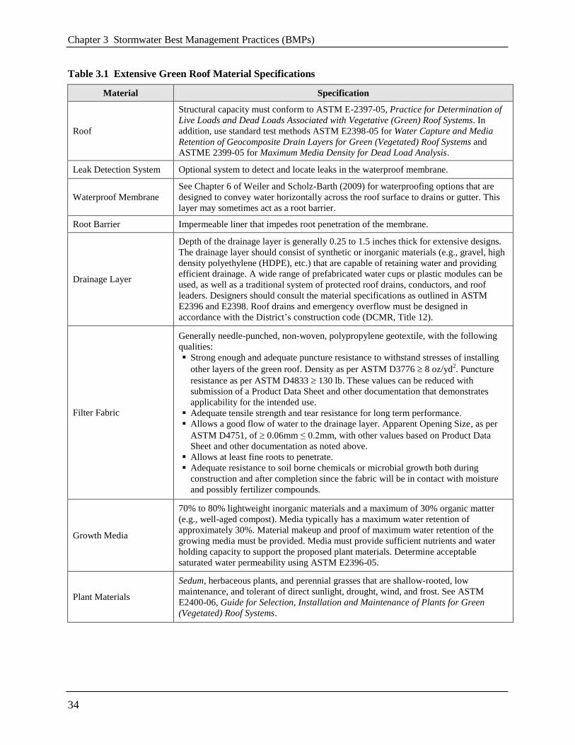
Chapter 3 Stormwater Best Management Practices (BMPs)
34
Table 3.1 Extensive Green Roof Material Specifications
Material Specification
Roof
Structural capacity must conform to ASTM E-2397-05, Practice for Determination of
Live Loads and Dead Loads Associated with Vegetative (Green) Roof Systems. In
addition, use standard test methods ASTM E2398-05 for Water Capture and Media
Retention of Geocomposite Drain Layers for Green (Vegetated) Roof Systems and
ASTME 2399-05 for Maximum Media Density for Dead Load Analysis.
Leak Detection System Optional system to detect and locate leaks in the waterproof membrane.
Waterproof Membrane
See Chapter 6 of Weiler and Scholz-Barth (2009) for waterproofing options that are
designed to convey water horizontally across the roof surface to drains or gutter. This
layer may sometimes act as a root barrier.
Root Barrier Impermeable liner that impedes root penetration of the membrane.
Drainage Layer
Depth of the drainage layer is generally 0.25 to 1.5 inches thick for extensive designs.
The drainage layer should consist of synthetic or inorganic materials (e.g., gravel, high
density polyethylene (HDPE), etc.) that are capable of retaining water and providing
efficient drainage. A wide range of prefabricated water cups or plastic modules can be
used, as well as a traditional system of protected roof drains, conductors, and roof
leaders. Designers should consult the material specifications as outlined in ASTM
E2396 and E2398. Roof drains and emergency overflow must be designed in
accordance with the District’s construction code (DCMR, Title 12).
Filter Fabric
Generally needle-punched, non-woven, polypropylene geotextile, with the following
qualities:
Strong enough and adequate puncture resistance to withstand stresses of installing
other layers of the green roof. Density as per ASTM D3776 8 oz/yd2. Puncture
resistance as per ASTM D4833 130 lb. These values can be reduced with
submission of a Product Data Sheet and other documentation that demonstrates
applicability for the intended use.
Adequate tensile strength and tear resistance for long term performance.
Allows a good flow of water to the drainage layer. Apparent Opening Size, as per
ASTM D4751, of 0.06mm ≤ 0.2mm, with other values based on Product Data
Sheet and other documentation as noted above.
Allows at least fine roots to penetrate.
Adequate resistance to soil borne chemicals or microbial growth both during
construction and after completion since the fabric will be in contact with moisture
and possibly fertilizer compounds.
Growth Media
70% to 80% lightweight inorganic materials and a maximum of 30% organic matter
(e.g., well-aged compost). Media typically has a maximum water retention of
approximately 30%. Material makeup and proof of maximum water retention of the
growing media must be provided. Media must provide sufficient nutrients and water
holding capacity to support the proposed plant materials. Determine acceptable
saturated water permeability using ASTM E2396-05.
Plant Materials
Sedum, herbaceous plants, and perennial grasses that are shallow-rooted, low
maintenance, and tolerant of direct sunlight, drought, wind, and frost. See ASTM
E2400-06, Guide for Selection, Installation and Maintenance of Plants for Green
(Vegetated) Roof Systems.

3.2 Green Roofs
35
Green Roof Sizing. Green roof areas can be designed to capture the entire Stormwater Retention
Volume (SWRv). In some cases, they could be designed to capture larger design storm volumes
as well. The required size of a green roof will depend on several factors, including maximum
water retention of the growing media and the underlying drainage and storage layer materials
(e.g., prefabricated water cups or plastic modules). As maximum water retention can vary
significantly between green roof products, verification of this value must be included with the
Stormwater Management Plan (SWMP). ASTM tests E2396, E2397, E2398, or E2399, as
appropriate, and performed by an ASTM-certified lab are considered acceptable verification. In
the absence of ASTM test results the baseline default values must be used. Site designers and
planners should consult with green roof manufacturers and material suppliers as they can often
provide specific sizing information and hydrology design tools for their products. Equation 3.1
below shall be used to determine the storage volume retained by a green roof.
Equation 3.1 Storage Volume for Green Roofs
12
+ 21
DLdSASv
where:
Sv = storage volume (ft3)
SA = green roof area (ft2)
d = media depth (in.) (minimum 3 in.)
1 = verified media maximum water retention (use 0.15 as a baseline default in the
absence of verification data)
DL = drainage layer depth (in.)
2 = verified drainage layer maximum water retention (use 0.15 as a baseline
default in the absence of verification data)
The appropriate Sv can then be compared to the required SWRv for the entire rooftop area
(including all conventional roof areas) to determine the portion of the design storm captured.
Green roofs can have dramatic rate attenuation effects on larger storm events and may be used,
in part, to manage a portion of the 2-year and 15-year events. Designers can model various
approaches by factoring in storage within the drainage layer. Routing calculations can also be
used to provide a more accurate solution of the peak discharge and required storage volume.
3.2.5 Green Roof Landscaping Criteria
Plant selection, landscaping, and maintenance are critical to the performance and function of
green roofs. Therefore, a landscaping plan shall be provided for green roofs.
A planting plan must be prepared for a green roof by a landscape architect, botanist, or other
professional experienced with green roofs and submitted with the SWMP.
Plant selection for green roofs is an integral design consideration, which is governed by local
climate and design objectives. The primary ground cover for most green roof installations is a

Chapter 3 Stormwater Best Management Practices (BMPs)
36
hardy, low-growing succulent, such as Sedum, Delosperma, Talinum, Semperivum, or Hieracium
that is matched to the local climate conditions and can tolerate the difficult growing conditions
found on building rooftops (Snodgrass and Snodgrass, 2006).
A list of some common green roof plant species that work well in the Chesapeake Bay watershed
can be found in Table 3.2 below.
Table 3.2 Ground Covers Appropriate for Green Roofs in the District of Columbia
Plant Light Moisture
Requirement
Notes
Delosperma cooperii Full Sun Dry Pink flowers; grows rapidly
Delosperma 'Kelaidis' Full Sun Dry Salmon flowers; grows rapidly
Delosperma nubigenum 'Basutoland' Full Sun Moist-Dry Yellow flowers; very hardy
Sedum album Full Sun Dry White flowers; hardy
Sedum lanceolatum Full Sun Dry Yellow flowers; native to U.S.
Sedum oreganum Part Shade Moist Yellow flowers; native to U.S.
Sedum stoloniferum Sun Moist Pink flowers; drought tolerant
Sedum telephiodes Sun Dry Blue green foliage; native to region
Sedum ternatum Part Shade Dry-Moist White flowers; grows in shade
Talinum calycinum Sun Dry Pink flowers; self-sows
Note: Designers should choose species based on shade tolerance, ability to sow or not, foliage height, and
spreading rate. See Snodgrass and Snodgrass (2006) for a definitive list of green roof plants, including accent
plants.
Plant choices can be much more diverse for deeper intensive green roof systems. Herbs,
forbs, grasses, shrubs, and even trees can be used, but designers should understand they may
have higher watering, weeding, and landscape maintenance requirements.
The species and layout of the planting plan must reflect the location of the building, in terms
of its height, exposure to wind, snow loading, heat stress, orientation to the sun, and impacts
from surrounding buildings. (Wind scour and solar burning have been observed on green roof
installations that failed to adequately account for neighboring building heights and
surrounding window reflectivity.) In addition, plants must be selected that are fire resistant
and able to withstand heat, cold, and high winds.
Designers should also match species to the expected rooting depth of the growing media,
which can also provide enough lateral growth to stabilize the growing media surface. The
planting plan should usually include several accent plants to provide diversity and seasonal
color. For a comprehensive resource on green roof plant selection, consult Snodgrass and
Snodgrass (2006).

3.2 Green Roofs
37
It is also important to note that most green roof plant species will not be native to the
Chesapeake Bay watershed (which contrasts with native plant recommendations for other
stormwater practices, such as bioretention and constructed wetlands).
Given the limited number of green roof plant nurseries in the region, it may be necessary for
designers to order plants 6 to 12 months prior to the expected planting date. It is also
advisable to have plant materials contract grown.
When appropriate species are selected, most green roofs will not require supplemental
irrigation, except for temporary irrigation during drought or initial establishment. The design
must provide for temporary, manual, and/or permanent irrigation or watering systems, and
the use of water efficient designs and/or use of non-potable sources is strongly encouraged.
The planting window extends from the spring to early fall; although, it is important to allow
plants to root thoroughly before the first killing frost. Green roof manufacturers and plant
suppliers may provide guidance on planting windows as well as winter care. Proper planting
and care may also be required for plant warranty eligibility.
Plants can be established using cuttings, plugs, mats, and, more rarely, seeding or containers.
Several vendors also sell mats, rolls, or proprietary green roof planting modules. For the pros
and cons of each method, see Snodgrass and Snodgrass (2006).
The goal for green roof systems designed for stormwater management is to establish a full
and vigorous cover of low-maintenance vegetation that is self-sustaining (not requiring
fertilizer inputs) and requires minimal mowing, trimming, and weeding.
The green roof design should include non-vegetated walkways (e.g., paver blocks) to allow for
easy access to the roof for weeding and making spot repairs (see Section 3.2.4 Green Roof
Design Criteria).
3.2.6 Green Roof Construction Sequence
Green Roof Installation. Given the diversity of extensive vegetated roof designs, there is no
typical step-by-step construction sequence for proper installation. The following general
construction considerations are noted:
Construct the roof deck with the appropriate slope and material.
Install the waterproofing method, according to manufacturer’s specifications.
Conduct a flood test to ensure the system is watertight by placing at least 2 inches of water
over the membrane for 48 hours to confirm the integrity of the waterproofing system.
Alternately, electric field vector mapping (EFVM) can be done to test for the presence of
leaks; however, not all impermeable membranes are testable with this method. Problems
have been noted with the use of EFVM on black EPDM and with aluminized protective
coatings commonly used in conjunction with modified bituminous membranes.
Add additional system components (e.g., insulation, root barrier, drainage layer and interior
drainage system, and filter fabric) per the manufacturer’s specifications, taking care not to
damage the waterproofing. Any damage occurring must be reported immediately. Drain
collars and protective flashing should be installed to ensure free flow of excess stormwater.

Chapter 3 Stormwater Best Management Practices (BMPs)
38
The growing media should be mixed prior to delivery to the site. Media must be spread
evenly over the filter fabric surface as required by the manufacturer. If a delay between the
installation of the growing media and the plants is required, adequate efforts must be taken to
secure the growing media from erosion and the seeding of weeds. The growing media must
be covered and anchored in place until planting. Sheets of exterior grade plywood can also be
laid over the growing media to accommodate foot or wheelbarrow traffic. Foot traffic and
equipment traffic should be limited over the growing media to reduce compaction beyond
manufacturer’s recommendations.
The growing media should be moistened prior to planting, and then planted with the ground
cover and other plant materials, per the planting plan or in accordance with ASTM E2400.
Plants should be watered immediately after installation and routinely during establishment.
It generally takes 2 to 3 growing seasons to fully establish the vegetated roof. The growing
medium should contain enough organic matter to support plants for the first growing season,
so initial fertilization is not required. Extensive green roofs may require supplemental
irrigation during the first few months of establishment. Hand weeding is also critical in the
first two years (see Table 10.1 of Weiler and Scholz-Barth (2009) for a photo guide of
common rooftop weeds).
Most construction contracts should contain a Care and Replacement Warranty that specifies
at least 50 percent coverage after one year and 80 percent coverage after two years for plugs
and cuttings, and 90 percent coverage after one year for Sedum carpet/tile.
Construction Supervision. Supervision during construction is recommended to ensure that the
vegetated roof is built in accordance with these specifications. Inspection checklists should be
used that include sign-offs by qualified individuals at critical stages of construction and confirm
that the contractor’s interpretation of the plan is consistent with the intent of the designer and/or
manufacturer.
An experienced installer should be retained to construct the vegetated roof system. The vegetated
roof should be constructed in sections for easier inspection and maintenance access to the
membrane and roof drains. Careful construction supervision/inspection is needed throughout the
installation of a vegetated roof, as follows:
During placement of the waterproofing layer, to ensure that it is properly installed and
watertight.
During placement of the drainage layer and drainage system.
During placement of the growing media, to confirm that it meets the specifications and is
applied to the correct depth (certification for vendor or source should be provided).
Upon installation of plants, to ensure they conform to the planting plan (certification from
vendor or source should be provided).
Before issuing use and occupancy approvals.
At the end of the first or second growing season to ensure desired surface cover specified in
the Care and Replacement Warranty has been achieved.

3.2 Green Roofs
39
DDOE’s construction phase inspection checklist for green roof practices can be found in
Appendix K.
3.2.7 Green Roof Maintenance Criteria
Maintenance Inspections. A green roof should be inspected by a qualified professional twice a
year during the growing season to assess vegetative cover and to look for leaks, drainage
problems, and any rooftop structural concerns (see Table 3.3). In addition, the green roof should
be hand weeded to remove invasive or volunteer plants, and plants and/or media should be added
to repair bare areas (refer to ASTM E2400 (ASTM, 2006)).
If a roof leak is suspected, it is advisable to perform an electric leak survey (e.g., EVFM), if
applicable, to pinpoint the exact location, make localized repairs, and then reestablish system
components and ground cover.
The use of herbicides, insecticides, and fungicides should be avoided, since their presence could
hasten degradation of some waterproofing membranes. Check with the membrane manufacturer
for approval and warranty information. Also, power washing and other exterior maintenance
operations should be avoided so that cleaning agents and other chemicals do not harm the green
roof plant communities.
Fertilization is generally not recommended due to the potential for leaching of nutrients from the
green roof. Supplemental fertilization may be required following the first growing season, but
only if plants show signs of nutrient deficiencies and a media test indicates a specific deficiency.
Addressing this issue with the holder of the vegetation warranty is recommended. If fertilizer is
to be applied, it must be a slow-release type, rather than liquid or gaseous form.
DDOE’s maintenance inspection checklist for green roofs and the Maintenance Service
Completion Inspection form can be found in Appendix L.
Table 3.3 Typical Maintenance Activities Associated with Green Roofs
Schedule
(following construction) Activity
As needed
or
as required by manufacturer
Water to promote plant growth and survival.
Inspect the green roof and replace any dead or dying vegetation.
Semi-annually
Inspect the waterproof membrane for leaks and cracks.
Weed to remove invasive plants (do not dig or use pointed tools where
there is potential to harm the root barrier or waterproof membrane).
Inspect roof drains, scuppers, and gutters to ensure they are not overgrown
and have not accumulated organic matter deposits. Remove any
accumulated organic matter or debris.
Inspect the green roof for dead, dying, or invasive vegetation. Plant
replacement vegetation as needed.

Chapter 3 Stormwater Best Management Practices (BMPs)
40
Declaration of Covenants. A declaration of covenants that includes all maintenance
responsibilities to ensure the continued stormwater performance for the BMP is required. The
declaration of covenants specifies the property owner’s primary maintenance responsibilities,
and authorizes DDOE staff to access the property for inspection or corrective action in the event
the proper maintenance is not performed. The declaration of covenants is attached to the deed of
the property. A template form is provided at the end of Chapter 5 (see Figure 5.4), although
variations will exist for scenarios where stormwater crosses property lines. The covenant is
between the property and the Government of the District of Columbia. It is submitted through the
Office of the Attorney General. All SWMPs have a maintenance agreement stamp that must be
signed for a building permit to proceed. A maintenance schedule must appear on the SWMP.
Additionally, a maintenance schedule is required in Exhibit C of the declaration of covenants.
Covenants are not required on government properties, but maintenance responsibilities must be
defined through a partnership agreement or a memorandum of understanding.
Waste Materials. Waste material from the repair, maintenance, or removal of a BMP or land
cover shall be removed and disposed of in compliance with applicable federal and District law.
3.2.8 Green Roof Stormwater Compliance Calculations
Green roofs receive 100 percent retention value for the amount of storage volume (Sv) provided
by the practice (see Table 3.4). Since the practice gets 100 percent retention value, it is not
considered an accepted total suspended solids (TSS) treatment practice.
Table 3.4 Green Roof Design Performance
Retention Value = Sv
Accepted TSS Treatment Practice N/A
The practice must be designed using the guidance detailed in Section 3.2.4.
Green roofs also contribute to peak flow reduction. This contribution can be determined in
several ways. One method is to subtract the Sv from the total runoff volume for the 2-year, 15-
year, and 100-year storms. The resulting reduced runoff volumes can then be used to calculate a
Reduced Natural Resource Conservation Service Curve Number for the site or drainage area.
The Reduced Curve Number can then be used to calculate peak flow rates for the various storm
events. Other hydrologic modeling tools that employ different procedures may be used as well.
3.2.9 References
ASTM International. 2006. Standard Guide for Selection, Installation and Maintenance of Plants
for Green (Vegetated) Roof Systems. Standard E2400-06. ASTM, International. West
Conshohocken, PA. available online: http://www.astm.org/Standards/ E2400.htm.
Clark, S., B. Long, C. Siu, J. Spicher and K. Steele. 2008. ―Early-life runoff quality: green versus
traditional roofs.‖ Low Impact Development 2008. Seattle, WA. American Society of Civil
Engineers.

3.2 Green Roofs
41
Dunnett, N. and N. Kingsbury. 2004. Planting Green Roofs and Living Walls. Timber Press.
Portland, Oregon.
Green Roof Infrastructure: Plants and Growing Medium 401. Participant Manual.
www.greenroofs.org
Luckett, K. 2009. Green Roof Construction and Maintenance. McGraw-Hill Companies, Inc.
Northern Virginia Regional Commission (NVRC). 2007. Low Impact Development Manual.
―Vegetated Roofs.‖ Fairfax, VA.
Snodgrass, E. and L. Snodgrass. 2006. Green Roof Plants: a resource and planting guide. Timber
Press. Portland, OR.
Weiler, S. and K. Scholz-Barth. 2009. Green Roof Systems: A Guide to the Planning, Design,
and Construction of Landscapes over Structure. Wiley Press. New York, NY.
Virginia DCR Stormwater Design Specification No. 5: Vegetated Roof Version 2.2. 2010.

3.3 Rainwater Harvesting
43
3.3 Rainwater Harvesting
Definition. Rainwater harvesting systems store rainfall and release it for future use. Rainwater
that falls on a rooftop or other impervious surface is collected and conveyed into an above- or
below-ground tank (also referred to as a cistern), where it is stored for non-potable uses or for
on-site disposal or infiltration as stormwater. Cisterns can be sized for commercial as well as
residential purposes. Residential cisterns are commonly called rain barrels.
Non-potable uses of harvested rainwater may include the following:
Landscape irrigation,
Exterior washing (e.g., car washes, building facades, sidewalks, street sweepers, and fire
trucks),
Flushing of toilets and urinals,
Fire suppression (i.e., sprinkler systems),
Supply for cooling towers, evaporative coolers, fluid coolers, and chillers,
Supplemental water for closed loop systems and steam boilers,
Replenishment of water features and water fountains,
Distribution to a green wall or living wall system,
Laundry, and
Delayed discharge to the combined sewer system.
In many instances, rainwater harvesting can be combined with a secondary (down-gradient)
stormwater practice to enhance stormwater retention and/or provide treatment of overflow from
the rainwater harvesting system. Some candidate secondary practices include the following:
Disconnection to a pervious area (compacted cover) or conservation area (natural cover) or
soil amended filter path (see Section 3.4 Impervious Surface Disconnection)
Overflow to bioretention practices (see Section 3.6 Bioretention)
Overflow to infiltration practices (see Section 3.8 Stormwater Infiltration)
Overflow to grass channels or dry swales (see Section 3.12 Storage Practices)
By providing a reliable and renewable source of water to end users, rainwater harvesting systems
can also have environmental and economic benefits beyond stormwater management (e.g.,
increased water conservation, water supply during drought and mandatory municipal water
supply restrictions, decreased demand on municipal water supply, decreased water costs for the
end user, and potential for increased groundwater recharge).

Chapter 3 Stormwater Best Management Practices (BMPs)
44
The seven primary components of a rainwater harvesting system are discussed in detail in
Section 3.3.4. Some are depicted in Figure 3.2. The components include the following:
Contributing drainage area (CDA) surface,
Collection and conveyance system (e.g., gutter and downspouts) (number 1 in Figure 3.2)
Pretreatment, including prescreening and first flush diverters (number 2 in Figure 3.2)
Cistern (no number, but depicted in Figure 3.2)
Water quality treatment (as required by Tiered Risk Assessment Management (TRAM))
Distribution system
Overflow, filter path or secondary stormwater retention practice (number 8 in Figure 3.2)
Figure 3.2 Example of a rainwater harvesting system detail.

3.3 Rainwater Harvesting
45
3.3.1 Rainwater Harvesting Feasibility Criteria
A number of site-specific features influence how rainwater harvesting systems are designed
and/or utilized. The following are key considerations for rainwater harvesting feasibility. They
are not comprehensive or conclusive; rather, they are recommendations to consider during the
planning process to incorporate rainwater harvesting systems into the site design.
Plumbing Code. This specification does not address indoor plumbing or disinfection issues.
Designers and plan reviewers should consult the District’s construction codes (DCMR, Title 12)
to determine the allowable indoor uses and required treatment for harvested rainwater. In cases
where a municipal backup supply is used, rainwater harvesting systems must have backflow
preventers or air gaps to keep harvested water separate from the main water supply. Distribution
and waste pipes, internal to the building, must be stamped non-potable and colored purple
consistent with the District’s building codes. Pipes and spigots using rainwater must be clearly
labeled as non-potable with an accompanying pictograph sign.
Mechanical, Electrical, Plumbing (MEP). For systems that call for indoor use of harvested
rainwater, the seal of an MEP engineer is required.
Water Use. When rainwater harvesting will be used, a TRAM (see Appendix M) must be
completed and the appropriate form submitted to DDOE. This will outline the design
assumptions, outline water quality risks and provide water quality end use standards.
Available Space. Adequate space is needed to house the cistern and any overflow. Space
limitations are rarely a concern with rainwater harvesting systems if they are considered during
the initial building design and site layout of a residential or commercial development. Cisterns
can be placed underground, indoors, adjacent to buildings, and on rooftops that are structurally
designed to support the added weight. Designers can work with architects and landscape
architects to creatively site the cisterns. Underground utilities or other obstructions should
always be identified prior to final determination of the cistern location.
Site Topography. Site topography and cistern location should be considered as they relate to all
of the inlet and outlet invert elevations in the rainwater harvesting system.
The final invert of the cistern outlet pipe at the discharge point must match the invert of the
receiving mechanism (e.g., natural channel, storm drain system) and be sufficiently sloped to
adequately convey this overflow. The elevation drops associated with the various components of
a rainwater harvesting system and the resulting invert elevations should be considered early in
the design, in order to ensure that the rainwater harvesting system is feasible for the particular
site.
Site topography and cistern location will also affect pumping requirements. Locating cisterns in
low areas will make it easier to get water into the cisterns; however, it will increase the amount
of pumping needed to distribute the harvested rainwater back into the building or to irrigated
areas situated on higher ground. Conversely, placing cisterns at higher elevations may require
larger diameter pipes with smaller slopes but will generally reduce the amount of pumping
needed for distribution. It is often best to locate a cistern close to the building or drainage area, to
limit the amount of pipe needed.

Chapter 3 Stormwater Best Management Practices (BMPs)
46
Available Hydraulic Head. The required hydraulic head depends on the intended use of the
water. For residential landscaping uses, the cistern may be sited up-gradient of the landscaping
areas or on a raised stand. Pumps are commonly used to convey stored rainwater to the end use
in order to provide the required head. When the water is being routed from the cistern to the
inside of a building for non-potable use, often a pump is used to feed a much smaller pressure
tank inside the building, which then serves the internal water demands. Cisterns can also use
gravity to accomplish indoor residential uses (e.g., laundry) that do not require high water
pressure.
Water Table. Underground storage tanks are most appropriate in areas where the tank can be
buried above the water table. The tank should be located in a manner that is not subject it to
flooding. In areas where the tank is to be buried partially below the water table, special design
features must be employed, such as sufficiently securing the tank (to keep it from floating), and
conducting buoyancy calculations when the tank is empty. The tank may need to be secured
appropriately with fasteners or weighted to avoid uplift buoyancy. The combined weight of the
tank and hold-down ballast must meet or exceed the buoyancy force of the cistern. The cistern
must also be installed according to the cistern manufacturer’s specifications.
Soils. Cisterns should only be placed on native soils or on fill in accordance with the
manufacturer's guidelines. The bearing capacity of the soil upon which the cistern will be placed
must be considered, as full cisterns can be very heavy. This is particularly important for above-
ground cisterns, as significant settling could cause the cistern to lean or in some cases to
potentially topple. A sufficient aggregate, or concrete foundation, may be appropriate depending
on the soils and cistern characteristics. Where the installation requires a foundation, the
foundation must be designed to support the cistern’s weight when the cistern is full consistent
with the bearing capacity of the soil and good engineering practice. The pH of the soil should
also be considered in relation to its interaction with the cistern material.
Proximity of Underground Utilities. All underground utilities must be taken into consideration
during the design of underground rainwater harvesting systems, treating all of the rainwater
harvesting system components and storm drains as typical stormwater facilities and pipes. The
underground utilities must be marked and avoided during the installation of underground cisterns
and piping associated with the system.
Contributing Drainage Area. The contributing drainage area (CDA) to the cistern is the
impervious area draining to the cistern. Rooftop surfaces are what typically make up the CDA,
but paved areas can be used with appropriate treatment (oil/water separators and/or debris
excluders). Areas of any size, including portions of roofs, can be used based on the sizing
guidelines in this design specification. Runoff should be routed directly from the drainage area to
rainwater harvesting systems in closed roof drain systems or storm drain pipes, avoiding surface
drainage, which could allow for increased contamination of the water.
Contributing Drainage Area Material. The quality of the harvested rainwater will vary
according to the roof material or drainage area over which it flows. Water harvested from certain
types of rooftops and CDAs, such as asphalt sealcoats, tar and gravel, painted roofs, galvanized
metal roofs, sheet metal, or any material that may contain asbestos may leach trace metals and
other toxic compounds. In general, harvesting rainwater from such surfaces should be avoided. If

3.3 Rainwater Harvesting
47
harvesting from a sealed or painted roof surface is desired, it is recommended that the sealant or
paint be certified for such purposes by the National Sanitation Foundation (ANSI/NSF standard).
Water Quality of Rainwater. Designers should also note that the pH of rainfall in the District
tends to be acidic (ranging from 4.5 to 5.0), which may result in leaching of metals from roof
surfaces, cistern lining or water laterals, to interior connections. Once rainfall leaves rooftop
surfaces, pH levels tend to be slightly higher, ranging from 5.5 to 6.0. Limestone or other
materials may be added in the cistern to buffer acidity, if desired.
Hotspot Land Uses. Harvesting rainwater can be an effective method to prevent contamination
of rooftop runoff that would result from mixing it with ground-level runoff from a stormwater
hotspot operation.
Setbacks from Buildings. Cistern overflow devices must be designed to avoid causing ponding
or soil saturation within 10 feet of building foundations. While most systems are generally sited
underground and more than ten feet laterally from the building foundation wall, some cisterns
are incorporated into the basement of a building or underground parking areas. In any case,
cisterns must be designed to be watertight to prevent water damage when placed near building
foundations.
Vehicle Loading. Whenever possible, underground rainwater harvesting systems should be
placed in areas without vehicle traffic or other heavy loading, such as deep earth fill. If site
constraints dictate otherwise, systems must be designed to support the loads to which they will
be subjected.
3.3.2 Rainwater Harvesting Conveyance Criteria
Collection and Conveyance. The collection and conveyance system consists of the gutters,
downspouts, and pipes that channel rainfall into cisterns. Gutters and downspouts should be
designed as they would for a building without a rainwater harvesting system. Aluminum, round-
bottom gutters and round downspouts are generally recommended for rainwater harvesting.
Typically, gutters should be hung at a minimum of 0.5 percent for 2/3 of the length and at 1
percent for the remaining 1/3 of the length in order to adequately convey the design storm (i.e..,
Stormwater Retention Volume (SWRv)). If the system will be used for management of the 2-
year and 15-year storms, the gutters must be designed to convey the appropriate 2-year and 15-
year storm intensities.
Pipes, which connect downspouts to the cistern, should be at a minimum slope of 1.5 percent and
sized/designed to convey the intended design storm, as specified above. In some cases, a steeper
slope and larger sizes may be recommended and/or necessary to convey the required runoff,
depending on the design objective and design storm intensity. Gutters and downspouts should be
kept clean and free of debris and rust.
Overflow. An overflow mechanism must be included in the rainwater harvesting system design
in order to handle an individual storm event or multiple storms in succession that exceed the
capacity of the cistern. Overflow pipe(s) must have a capacity equal to or greater than the inflow
pipe(s) and have a diameter and slope sufficient to drain the cistern while maintaining an
adequate freeboard height. The overflow pipe(s) must be screened to prevent access to the cistern
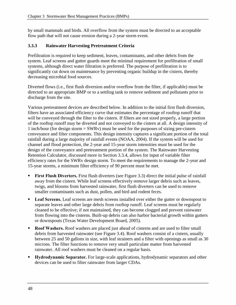
Chapter 3 Stormwater Best Management Practices (BMPs)
48
by small mammals and birds. All overflow from the system must be directed to an acceptable
flow path that will not cause erosion during a 2-year storm event.
3.3.3 Rainwater Harvesting Pretreatment Criteria
Prefiltration is required to keep sediment, leaves, contaminants, and other debris from the
system. Leaf screens and gutter guards meet the minimal requirement for prefiltration of small
systems, although direct water filtration is preferred. The purpose of prefiltration is to
significantly cut down on maintenance by preventing organic buildup in the cistern, thereby
decreasing microbial food sources.
Diverted flows (i.e., first flush diversion and/or overflow from the filter, if applicable) must be
directed to an appropriate BMP or to a settling tank to remove sediment and pollutants prior to
discharge from the site.
Various pretreatment devices are described below. In addition to the initial first flush diversion,
filters have an associated efficiency curve that estimates the percentage of rooftop runoff that
will be conveyed through the filter to the cistern. If filters are not sized properly, a large portion
of the rooftop runoff may be diverted and not conveyed to the cistern at all. A design intensity of
1 inch/hour (for design storm = SWRv) must be used for the purposes of sizing pre-cistern
conveyance and filter components. This design intensity captures a significant portion of the total
rainfall during a large majority of rainfall events (NOAA, 2004). If the system will be used for
channel and flood protection, the 2-year and 15-year storm intensities must be used for the
design of the conveyance and pretreatment portion of the system. The Rainwater Harvesting
Retention Calculator, discussed more in Section 3.3.4, allows for input of variable filter
efficiency rates for the SWRv design storm. To meet the requirements to manage the 2-year and
15-year storms, a minimum filter efficiency of 90 percent must be met.
First Flush Diverters. First flush diverters (see Figure 3.3) direct the initial pulse of rainfall
away from the cistern. While leaf screens effectively remove larger debris such as leaves,
twigs, and blooms from harvested rainwater, first flush diverters can be used to remove
smaller contaminants such as dust, pollen, and bird and rodent feces.
Leaf Screens. Leaf screens are mesh screens installed over either the gutter or downspout to
separate leaves and other large debris from rooftop runoff. Leaf screens must be regularly
cleaned to be effective; if not maintained, they can become clogged and prevent rainwater
from flowing into the cisterns. Built-up debris can also harbor bacterial growth within gutters
or downspouts (Texas Water Development Board, 2005).
Roof Washers. Roof washers are placed just ahead of cisterns and are used to filter small
debris from harvested rainwater (see Figure 3.4). Roof washers consist of a cistern, usually
between 25 and 50 gallons in size, with leaf strainers and a filter with openings as small as 30
microns. The filter functions to remove very small particulate matter from harvested
rainwater. All roof washers must be cleaned on a regular basis.
Hydrodynamic Separator. For large-scale applications, hydrodynamic separators and other
devices can be used to filter rainwater from larger CDAs.
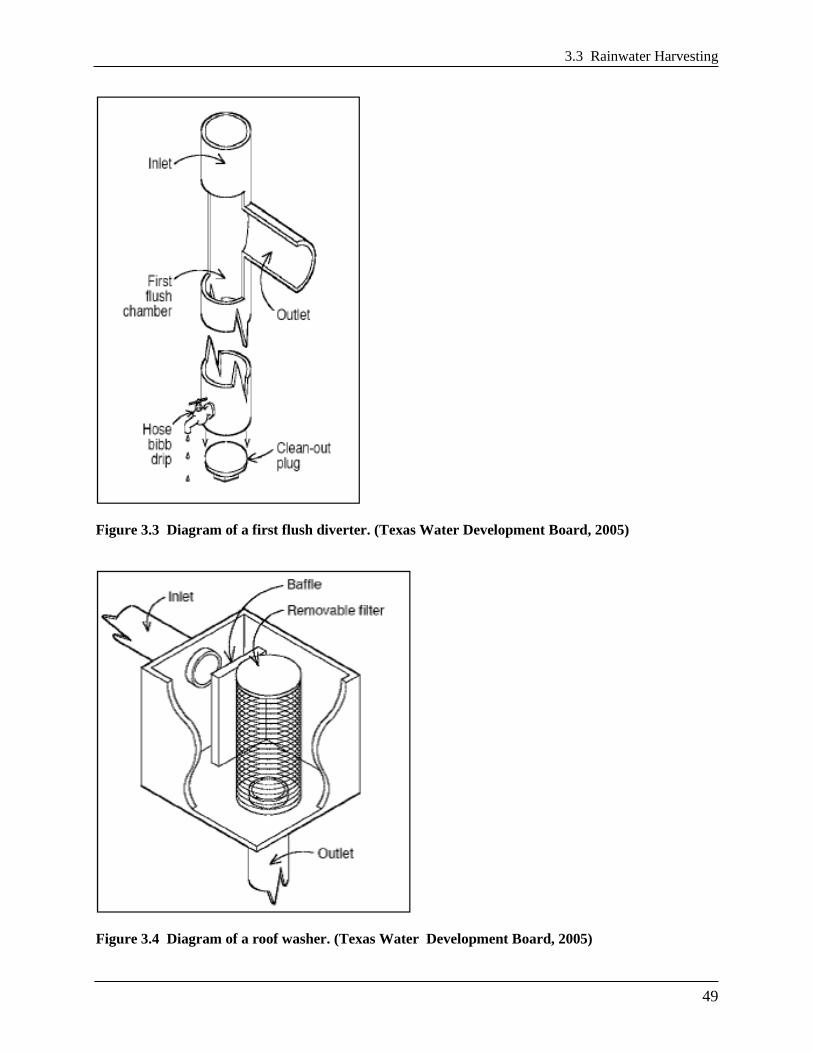
3.3 Rainwater Harvesting
49
Figure 3.3 Diagram of a first flush diverter. (Texas Water Development Board, 2005)
Figure 3.4 Diagram of a roof washer. (Texas Water Development Board, 2005)

Chapter 3 Stormwater Best Management Practices (BMPs)
50
3.3.4 Rainwater Harvesting Design Criteria
System Components: Seven primary components of a rainwater harvesting system require
special considerations (some of these are depicted in Figure 3.2):
CDA or CDA surface
Collection and conveyance system (i.e., gutter and downspouts)
Cisterns
Pretreatment, including prescreening and first flush diverters
Water quality treatment (as required by TRAM)
Distribution systems
Overflow, filter path or secondary stormwater retention practice
The system components are discussed below:
CDA Surface. When considering CDA surfaces, note smooth, non-porous materials will
drain more efficiently. Slow drainage of the CDA leads to poor rinsing and a prolonged first
flush, which can decrease water quality. If the harvested rainwater will be directed towards
uses with significant human exposure (e.g., pool filling, public sprinkler fountain), care
should be taken in the choice of CDA materials. Some materials may leach toxic chemicals
making the water unsafe for humans. In all cases, follow the advice of the TRAM found in
Appendix M.
Rainwater can also be harvested from other impervious surfaces, such as parking lots and
driveways; however, this practice requires more extensive pretreatment and treatment prior to
reuse.
Collection and Conveyance System. See Section 3.3.2 Rainwater Harvesting Conveyance
Criteria.
Pretreatment. See Section 3.3.3 Rainwater Harvesting Pretreatment Criteria.
Cisterns. The cistern is the most important and typically the most expensive component of a
rainwater harvesting system. Cistern capacities generally range from 250 to 30,000 gallons,
but they can be as large as 100,000 gallons or more for larger projects. Multiple cisterns can
be placed adjacent to each other and connected with pipes to balance water levels and to
tailor the storage volume needed. Typical rainwater harvesting system capacities for
residential use range from 1,500 to 5,000 gallons. Cistern volumes are calculated to meet the
water demand and stormwater storage volume retention objectives, as described further
below in this specification.
While many of the graphics and photos in this specification depict cisterns with a cylindrical
shape, the cisterns can be made of many materials and configured in various shapes,
depending on the type used and the site conditions where the cisterns will be installed. For
example, configurations can be rectangular, L-shaped, or step vertically to match the
topography of a site. The following factors should be considered when designing a rainwater
harvesting system and selecting a cistern:

3.3 Rainwater Harvesting
51
Aboveground cisterns should be ultraviolet and impact resistant.
Underground cisterns must be designed to support the overlying sediment and any other
anticipated loads (e.g., vehicles, pedestrian traffic).
Underground rainwater harvesting systems must have a standard size manhole or
equivalent opening to allow access for cleaning, inspection, and maintenance purposes.
The access opening must be installed in such a way as to prevent surface- or groundwater
from entering through the top of any fittings, and it must be secured/locked to prevent
unwanted entry. Confined space safety precautions/requirements should be observed
during cleaning, inspection, and maintenance.
All rainwater harvesting systems must be sealed using a water-safe, non-toxic substance.
Rainwater harvesting systems may be ordered from a manufacturer or can be constructed
on site from a variety of materials. Table 3.5 below compares the advantages and
disadvantages of different cistern materials.
Cisterns must be opaque or otherwise protected from direct sunlight to inhibit growth of
algae, and they must be screened to discourage mosquito breeding.
Dead storage below the outlet to the distribution system and an air gap at the top of the
cistern must be included in the total cistern volume. For gravity-fed systems, a minimum
of 6 inches of dead storage must be provided. For systems using a pump, the dead storage
depth will be based on the pump specifications.
Any hookup to a municipal backup water supply must have a backflow prevention device
to keep municipal water separate from stored rainwater; this may include incorporating
an air gap to separate the two supplies.
Table 3.5 Advantages and Disadvantages of Typical Cistern Materials (Source: Cabell Brand
Center, 2007; Cabell Brand Center, 2009)
Cistern Material Advantages Disadvantages
Fiberglass Commercially available, alterable and
moveable; durable with little maintenance;
light weight; integral fittings (no leaks);
broad application
Must be installed on smooth, solid, level
footing; pressure proof for below-ground
installation; expensive in smaller sizes
Polyethylene Commercially available, alterable,
moveable, affordable; available in wide
range of sizes; can install above or below
ground; little maintenance; broad application
Can be UV-degradable; must be painted or
tinted for above-ground installations;
pressure-proof for below- ground
installation
Modular Storage Can modify to topography; can alter
footprint and create various shapes to fit site;
relatively inexpensive
Longevity may be less than other materials;
higher risk of puncturing of watertight
membrane during construction
Plastic Barrels Commercially available; inexpensive Low storage capacity (20 to 50 gallons);
limited application
Galvanized Steel Commercially available, alterable, and
moveable; available in a range of sizes; film
develops inside to prevent corrosion
Possible external corrosion and rust;
must be lined for potable use; can only
install above ground; soil pH may limit
underground applications
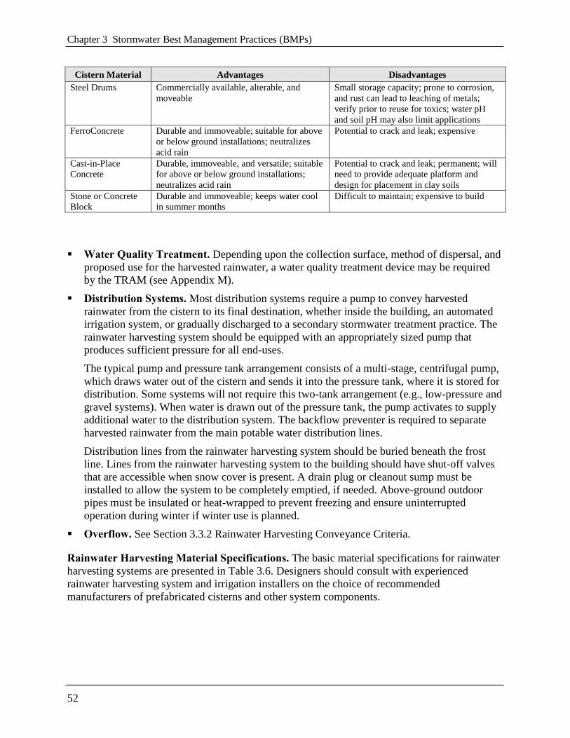
Chapter 3 Stormwater Best Management Practices (BMPs)
52
Cistern Material Advantages Disadvantages
Steel Drums Commercially available, alterable, and
moveable
Small storage capacity; prone to corrosion,
and rust can lead to leaching of metals;
verify prior to reuse for toxics; water pH
and soil pH may also limit applications
FerroConcrete Durable and immoveable; suitable for above
or below ground installations; neutralizes
acid rain
Potential to crack and leak; expensive
Cast-in-Place
Concrete
Durable, immoveable, and versatile; suitable
for above or below ground installations;
neutralizes acid rain
Potential to crack and leak; permanent; will
need to provide adequate platform and
design for placement in clay soils
Stone or Concrete
Block
Durable and immoveable; keeps water cool
in summer months
Difficult to maintain; expensive to build
Water Quality Treatment. Depending upon the collection surface, method of dispersal, and
proposed use for the harvested rainwater, a water quality treatment device may be required
by the TRAM (see Appendix M).
Distribution Systems. Most distribution systems require a pump to convey harvested
rainwater from the cistern to its final destination, whether inside the building, an automated
irrigation system, or gradually discharged to a secondary stormwater treatment practice. The
rainwater harvesting system should be equipped with an appropriately sized pump that
produces sufficient pressure for all end-uses.
The typical pump and pressure tank arrangement consists of a multi-stage, centrifugal pump,
which draws water out of the cistern and sends it into the pressure tank, where it is stored for
distribution. Some systems will not require this two-tank arrangement (e.g., low-pressure and
gravel systems). When water is drawn out of the pressure tank, the pump activates to supply
additional water to the distribution system. The backflow preventer is required to separate
harvested rainwater from the main potable water distribution lines.
Distribution lines from the rainwater harvesting system should be buried beneath the frost
line. Lines from the rainwater harvesting system to the building should have shut-off valves
that are accessible when snow cover is present. A drain plug or cleanout sump must be
installed to allow the system to be completely emptied, if needed. Above-ground outdoor
pipes must be insulated or heat-wrapped to prevent freezing and ensure uninterrupted
operation during winter if winter use is planned.
Overflow. See Section 3.3.2 Rainwater Harvesting Conveyance Criteria.
Rainwater Harvesting Material Specifications. The basic material specifications for rainwater
harvesting systems are presented in Table 3.6. Designers should consult with experienced
rainwater harvesting system and irrigation installers on the choice of recommended
manufacturers of prefabricated cisterns and other system components.

3.3 Rainwater Harvesting
53
Table 3.6 Design Specifications for Rainwater Harvesting Systems
Item Specification
Gutters
and
Downspouts
Materials commonly used for gutters and downspouts include polyvinylchloride (PVC) pipe,
vinyl, aluminum, and galvanized steel. Lead must not be used as gutter and downspout solder,
since rainwater can dissolve the lead and contaminate the water supply.
The length of gutters and downspouts is determined by the size and layout of the catchment
and the location of the cisterns.
Be sure to include needed bends and tees.
Pretreatment
At least one of the following (all rainwater to pass through pretreatment):
First flush diverter
Hydrodynamic separator
Roof washer
Leaf and mosquito screen (1 mm mesh size)
Cisterns
Materials used to construct cisterns must be structurally sound.
Cisterns should be constructed in areas of the site where soils can support the load associated
with stored water.
Cisterns must be watertight and sealed using a water-safe, non-toxic substance.
Cisterns must be opaque or otherwise shielded to prevent the growth of algae.
The size of the rainwater harvesting system(s) is determined through design calculations.
Note: This table does not address indoor systems or pumps.
Design Objectives and System Configuration. Rainwater harvesting systems can have many
design variations that meet user demand and stormwater objectives. This specification provides a
design framework to achieve the SWRv objectives that are required to comply with the
regulations, and it adheres to the following concepts:
Give preference to use of rainwater as a resource to meet on-site demand or in conjunction
with other stormwater retention practices.
Reduce peak flow by achieving volume reduction and temporary storage of runoff.
Based on these concepts, this specification focuses on system design configurations that harvest
rainwater for internal building uses, seasonal irrigation, and other activities, such as cooling
tower use and vehicle washing. While harvested rainwater will be in year-round demand for
many internal building uses, some other uses will have varied demand depending on the time of
year (e.g., cooling towers and seasonal irrigation). Thus, a lower retention value is assigned to a
type of use that has reduced demand.
Design Objectives and Cistern Design Set-Ups. Prefabricated rainwater harvesting cisterns
typically range in size from 250 to over 30,000 gallons. Three basic cistern designs meet the
various rainwater harvesting system configurations in this section.

Chapter 3 Stormwater Best Management Practices (BMPs)
54
Cistern Design 1. The first cistern set-up (Figure 3.5) maximizes the available storage
volume associated with the SWRv to meet the desired level of stormwater retention. This
layout also maximizes the storage that can be used to meet a demand. An emergency
overflow exists near the top of the cistern as the only gravity release outlet device (not
including the pump, manway, or inlets). It should be noted that it is possible to address 2-
year and 15-year storm volumes with this cistern configuration, but the primary purpose is to
address the smaller SWRv design storm.
Figure 3.5 Cistern Design 1: Storage associated with the design storm volume only.

3.3 Rainwater Harvesting
55
Cistern Design 2. The second cistern set-up (Figure 3.6) uses cistern storage to meet the
SWRv storage objectives and also uses additional detention volume to meet some or all of
the 2-year and 15-year storm volume requirements. An orifice outlet is provided at the top of
the design storage for the SWRv level, and an emergency overflow is located at the top of the
detention volume level.
Figure 3.6 Cistern Design 2: Storage associated with design storm, channel protection, and flood
volume.
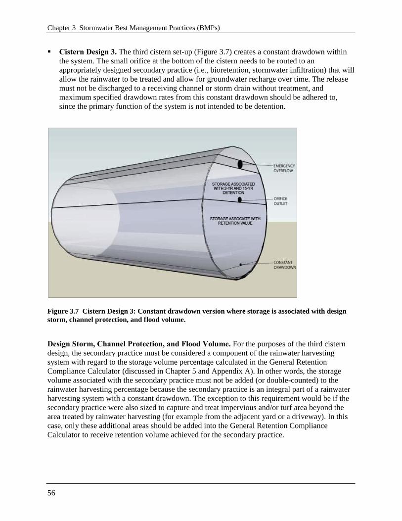
Chapter 3 Stormwater Best Management Practices (BMPs)
56
Cistern Design 3. The third cistern set-up (Figure 3.7) creates a constant drawdown within
the system. The small orifice at the bottom of the cistern needs to be routed to an
appropriately designed secondary practice (i.e., bioretention, stormwater infiltration) that will
allow the rainwater to be treated and allow for groundwater recharge over time. The release
must not be discharged to a receiving channel or storm drain without treatment, and
maximum specified drawdown rates from this constant drawdown should be adhered to,
since the primary function of the system is not intended to be detention.
Figure 3.7 Cistern Design 3: Constant drawdown version where storage is associated with design
storm, channel protection, and flood volume.
Design Storm, Channel Protection, and Flood Volume. For the purposes of the third cistern
design, the secondary practice must be considered a component of the rainwater harvesting
system with regard to the storage volume percentage calculated in the General Retention
Compliance Calculator (discussed in Chapter 5 and Appendix A). In other words, the storage
volume associated with the secondary practice must not be added (or double-counted) to the
rainwater harvesting percentage because the secondary practice is an integral part of a rainwater
harvesting system with a constant drawdown. The exception to this requirement would be if the
secondary practice were also sized to capture and treat impervious and/or turf area beyond the
area treated by rainwater harvesting (for example from the adjacent yard or a driveway). In this
case, only these additional areas should be added into the General Retention Compliance
Calculator to receive retention volume achieved for the secondary practice.

3.3 Rainwater Harvesting
57
While a small orifice is shown at the bottom of the cistern in Figure 3.7, the orifice could be
replaced with a pump that would serve the same purpose, conveying a limited amount of water to
a secondary practice on a routine basis.
Sizing of Rainwater Harvesting Systems. The rainwater harvesting cistern sizing criteria
presented in this section were developed using a spreadsheet model that used best estimates of
indoor and outdoor water demand, long-term rainfall data, and CDA capture area data
(Forasté2011). The Rainwater Harvesting Retention Calculator is for cistern sizing guidance and
to quantify the retention value for storage volume achieved. This retention value is required for
input into the General Retention Compliance Calculator and is part of the submission of a
Stormwater Management Plan (SWMP) using rainwater harvesting systems for compliance. A
secondary objective of the spreadsheet is to increase the beneficial uses of the stored stormwater,
treating it as a valuable natural resource. More information on the Rainwater Harvesting
Retention Calculator can be found later in this section. The spreadsheet can be found on DDOE’s
website at http://ddoe.dc.gov/swregs.
Rainwater Harvesting Retention Calculator. The design specification provided in this section
(Rainwater Harvesting) is linked with the Rainwater Harvesting Retention Calculator. The
spreadsheet uses daily rainfall data from September 1, 1977 to September 30, 2007 to model
performance parameters of the cistern under varying CDAs, demands on the system, and cistern
size.
The runoff that reaches the cistern each day is added to the water level that existed in the cistern
the previous day, with all of the total demands subtracted on a daily basis. If any overflow is
realized, the volume is quantified and recorded. If the cistern runs dry (reaches the cut-off
volume level), then the volume in the cistern is fixed at the low level, and a dry-frequency day is
recorded. The full or partial demand met in both cases is quantified and recorded. A summary of
the water balance for the system is provided below.
Incremental Design Volumes within Cistern. Rainwater cistern sizing is determined by
accounting for varying precipitation levels, captured CDA runoff, first flush diversion (through
filters) and filter efficiency, low water cut-off volume, dynamic water levels at the beginning of
various storms, storage needed for the design storm (permanent storage), storage needed for 2-
year or 15-year volume (temporary detention storage), seasonal and year-round demand use and
objectives, overflow volume, and freeboard volumes above high water levels during very large
storms. See Figure 3.8 for a graphical representation of these various incremental design
volumes.
The design specification described in this section (Rainwater Harvesting) does not provide
guidance for sizing larger storms (e.g., Qp2, Qp15, and Qf), but rather provides guidance on sizing
for the SWRv design storms.

Chapter 3 Stormwater Best Management Practices (BMPs)
58
Figure 3.8 Incremental design volumes associated with cistern sizing.
The ―Storage Associated with the Retention Value‖ is the storage within the cistern that is
modeled and available for reuse. While the SWRv will remain the same for a specific CDA, the
―Storage Associated with the Retention Value‖ may vary depending on demand and storage
volume retention objectives. It includes the variable water level at the beginning of a storm and
the low water cut-off volume that is necessary to satisfy pumping requirements.
Water Contribution
Precipitation. The volume of water contributing to the rainwater harvesting system is a
function of the rainfall and CDA, as defined by the designer.
Municipal Backup (optional). In some cases, the designer may choose to install a municipal
backup water supply to supplement cistern levels. Note that municipal backups may also be
connected post-cistern (i.e., a connection is made to the non-potable water line that is used
for pumping water from the cistern for reuse), thereby not contributing any additional volume
to the cistern. Municipal backup designs that supply water directly to the cistern are not
accounted for in the Rainwater Harvesting Retention Calculator.

3.3 Rainwater Harvesting
59
Water Losses
Drainage Area Runoff Coefficient. The CDA is assumed to convey 95 percent of the
rainfall that lands on its surface (i.e., Rv = 0.95).
First Flush Diversion. The first 0.02 to 0.06 inches of rainfall that is directed to filters is
diverted from the system in order to prevent clogging it with debris. This value is assumed to
be contained within the filter efficiency rate.
Filter Efficiency. It is assumed that, after the first flush diversion and loss of water due to
filter inefficiencies, the remainder of the SWRv storm will be successfully captured. For the
1.2-inch storm, a minimum of 95 percent of the runoff should be conveyed into the cistern.
For the 3.2-inch storm, a minimum of 90 percent of the runoff should be conveyed. These
minimum values are included as the filter efficiencies in the Rainwater Harvesting Retention
Calculator, although they can be altered (increased) if appropriate. The Rainwater Harvesting
Retention Calculator applies these filter efficiencies, or interpolated values, to the daily
rainfall record to determine the volume of runoff that reaches the cistern. For the purposes of
selecting an appropriately sized filter, a rainfall intensity of 1 inch per hour shall be used for
the SWRv. The appropriate rainfall intensity values for the 2-year (3.2-inch) and 15-year
storms shall be used when designing for larger storm events.
Drawdown (Storage Volume). This is the stored water within the cistern that is reused or
directed to a secondary stormwater practice. It is the volume of runoff that is reduced from
the CDA. This is the water loss that translates into the achievable storage volume retention.
Overflow. For the purposes of addressing the SWRv (not for addressing larger storm
volumes), orifice outlets for both detention and emergency overflows are treated the same.
This is the volume of water that may be lost during large storm events or successive
precipitation events.
Results for all Precipitation Events. The performance results of the rainwater harvesting
system for all days during the entire period modeled, including the full spectrum of precipitation
events, is included in the ―Results‖ tab. This tab is not associated with determining the storage
volume achieved, but instead may be a useful tool in assisting the user to realize the performance
of the various rainwater harvesting system sizes with the design parameters and demands
specified.
Percentage of Demand Met. This is where the percentage of demand met for various size
cisterns and CDA/demand scenarios is reported. A graph displaying the percentage of
demand met versus the percentage of overflow frequency for various cistern sizes is provided
in this tab. Normally, this graph assists the user in understanding the relationship between
cistern sizes and optimal/diminishing returns. An example is provided below in Figure 3.9.
At some point, larger cisterns no longer provide significant increases in percentages of
demand met. Conversely, the curve informs the user when a small increase in cistern size can
yield a significant increase in the percentage of time that demand is met.

Chapter 3 Stormwater Best Management Practices (BMPs)
60
Figure 3.9 Example of percent demand met versus cistern storage.
Dry Frequency. Another useful measure is the dry frequency. If the cistern is dry a
substantial portion of the time, this measure can inform the user that he/she may want to
decrease the size of the cistern, decrease the demand on the system, or explore capturing
more CDA to provide a larger supply, if feasible. It can also provide useful insight for the
designer to determine whether he/she should incorporate a municipal backup supply to
ensure sufficient water supply through the system at all times.
Overflow Frequency. This is a metric of both overflow frequency and average volume per
year for the full spectrum of rainfall events. This metric will inform the user regarding the
design parameters, magnitude of demand, and associated performance of the system. If the
system overflows at a high frequency, then the designer may want to increase the size of the
cistern, decrease the CDA captured, or consider other mechanisms that could increase
drawdown (e.g., increase the area to be irrigated, incorporate or increase on-site infiltration,
etc.).
Inter-relationships and Curves of Diminishing Returns. Plotting various performance
metrics against one another can be very informative and reveal relationships that are not
evident otherwise. An example of this usefulness is demonstrated when the plot of
―percentage-of-demand-met versus cistern size‖ is compared against the plot of ―the
percentage-of-overflow-frequency versus cistern size.‖ By depicting these plots on the same
graph, a range of optimum cistern sizes emerges. This informs the designer where a small
increase or decrease in cistern size will have a significant impact on dry frequency and
overflow frequency. Looking outside this range will indicate where changes in cistern sizes

3.3 Rainwater Harvesting
61
will not have significant influence over dry frequency and overflow frequency, but may offer
a large trade-off compared to the cost of the rainwater harvesting system.
Results for Retention Value. The retention value percentage of CDA runoff volume that the
cistern can capture for a 1.7-inch storm on an average daily basis given the water demands by the
user is presented on the ―Results-Retention Value‖ tab. This information is used to calculate the
retention value percentage, which is used as an input to the General Retention Compliance
Calculator.
Retention Value Percentage Achieved. The percentage of retention value achieved is
calculated for multiple sizes of cisterns. A trade-off curve plots these results, which allows
for a comparison of the retention achieved versus cistern size. While larger cisterns yield
more retention, they are more costly. The curve helps the user to choose the appropriate
cistern size, based on the design objectives and site needs, and to understand the rate of
diminishing returns.
Overflow Volume. The volume of the overflows resulting from a 1.7-inch precipitation
event is also reported in this tab. A chart of the retention value and overflow frequency
versus the storage volume is provided. An example is shown in Figure 3.10.
These plotted results establish a trade-off relationship between these two performance
metrics. In the example in Figure 3.10, a 13,000 gallon cistern optimizes the storage volume
achieved and the overflow frequency (near the inflection point of both curves).
Figure 3.10 Example of retention value percentage achieved versus storage for non-potable uses.

Chapter 3 Stormwater Best Management Practices (BMPs)
62
Results from the Rainwater Harvesting Retention Calculator to be Transferred to the
General Retention Compliance Calculator. There are two results from the Rainwater
Harvesting Retention Calculator that are to be transferred to the General Retention Compliance
Calculator, as follows:
Contributing Drainage Area (CDA). Enter the CDA that was used in the Rainwater
Harvesting Retention Calculator in the same row into the Drainage Area columns in the blue
cell (cell B26-D31).
Retention Value. Once the cistern storage volume associated with the retention value has
been selected, transfer that achieved percentage into the General Retention Compliance
Calculator column called ―% Retention Value‖ in the ―Rainwater Harvesting‖ row (cell I33).
Completing the Sizing Design of the Cistern. The total size of the cistern is the sum of the
following four volume components:
Low Water Cutoff Volume (Included). A dead storage area must be included so the pump
will not run the cistern dry. This volume is included in the Rainwater Harvesting Retention
Calculator’s modeled volume.
Cistern Storage Associated with Design Volume (Included). This is the design volume
from the Rainwater Harvesting Retention Calculator.
Adding Channel Protection and Flood Volumes (Optional). Additional detention volume
may be added above and beyond the cistern storage associated with the design storm volumes
for the 2-year or 15-year events. Typical routing software programs may be used to design
for this additional volume.
Adding Overflow and Freeboard Volumes (Required). An additional volume above the
emergency overflow must be provided in order for the cistern to allow very large storms to
pass. Above this overflow water level, there will be an associated freeboard volume that
should account for at least 5 percent of the overall cistern size. Sufficient freeboard must be
verified for large storms, and these volumes must be included in the overall size of the
cistern.
3.3.5 Rainwater Harvesting Landscaping Criteria
If the harvested water is to be used for irrigation, the design plan elements must include the
proposed delineation of planting areas to be irrigated, the planting plan, and quantification of the
expected water demand. The default water demand for irrigation is 1.0 inches per week over the
area to be irrigated. Justification must be provided if larger volumes are to be used.
3.3.6 Rainwater Harvesting Construction Sequence
Installation. It is advisable to have a single contractor to install the rainwater harvesting system,
outdoor irrigation system, and secondary retention practices. The contractor should be familiar
with rainwater harvesting system sizing, installation, and placement. A licensed plumber is
required to install the rainwater harvesting system components to the plumbing system.

3.3 Rainwater Harvesting
63
A standard construction sequence for proper rainwater harvesting system installation is provided
below. This can be modified to reflect different rainwater harvesting system applications or
expected site conditions.
1. Choose the cistern location on the site
2. Route all downspouts or pipes to prescreening devices and first flush diverters
3. Properly install the cistern
4. Install the pump (if needed) and piping to end uses (indoor, outdoor irrigation, or cistern
dewatering release)
5. Route all pipes to the cistern
6. Stormwater must not be diverted to the rainwater harvesting system until the overflow filter
path has been stabilized with vegetation.
Construction Supervision. The following items should be inspected by a qualified professional
prior to final sign-off and acceptance of a rainwater harvesting system:
Rooftop area matches plans
Diversion system is properly sized and installed
Pretreatment system is installed
Mosquito screens are installed on all openings
Overflow device is directed as shown on plans
Rainwater harvesting system foundation is constructed as shown on plans
Catchment area and overflow area are stabilized
Secondary stormwater treatment practice(s) is installed as shown on plans
DDOE’s construction phase inspection checklist for rainwater harvesting practices and the
Stormwater Facility Leak Test form can be found in Appendix K.
3.3.7 Rainwater Harvesting Maintenance Criteria
Maintenance Inspections. Periodic inspections and maintenance shall be conducted for each
system by a qualified professional.
DDOE’s maintenance inspection checklists for rainwater harvesting systems and the
Maintenance Service Completion Inspection form can be found in Appendix L.
Maintenance Schedule. Maintenance requirements for rainwater harvesting systems vary
according to use. Systems that are used to provide supplemental irrigation water have relatively
low maintenance requirements, while systems designed for indoor uses have much higher
maintenance requirements. Table 3.7 describes routine maintenance tasks necessary to keep
rainwater harvesting systems in working condition. Maintenance tasks must be performed by an
―Inspector Specialist,‖ certified by the American Rainwater Catchment Association.

Chapter 3 Stormwater Best Management Practices (BMPs)
64
Maintenance tasks must be documented and substantially comply with the maintenance
responsibilities outlined in the declaration of covenants.
Table 3.7 Typical Maintenance Tasks for Rainwater Harvesting Systems
Responsible
Person
Frequency Activity
Owner
Four times a year Inspect and clean prescreening devices and first flush diverters
Twice a year Keep gutters and downspouts free of leaves and other debris
Once a year
Inspect and clean storage cistern lids, paying special attention to
vents and screens on inflow and outflow spigots. Check mosquito
screens and patch holes or gaps immediately
Inspect condition of overflow pipes, overflow filter path, and/or
secondary stormwater treatment practices
Every third year Clear overhanging vegetation and trees over roof surface
Qualified
Third Party
Inspector
According to Manufacturer Inspect water quality devices
As indicated in TRAM Provide water quality analysis to DDOE
Every third year
Inspect cistern for sediment buildup
Check integrity of backflow preventer
Inspect structural integrity of cistern, pump, pipe and electrical
system
Replace damaged or defective system components
Mosquitoes. In some situations, poorly designed rainwater harvesting systems can create habitat
suitable for mosquito breeding. Designers must provide screens on above- and below-ground
cisterns to prevent mosquitoes and other insects from entering the cisterns. If screening is not
sufficient in deterring mosquitoes, dunks or pellets containing larvicide can be added to cisterns
when water is intended for landscaping use.
Cold Climate Considerations. Rainwater harvesting systems have a number of components that
can be impacted by freezing temperatures. Designers should give careful consideration to these
conditions to prevent system damage and costly repairs.
For above-ground systems, wintertime operation may be more challenging, depending on cistern
size and whether heat tape is used on piping. If not protected from freezing, these rainwater
harvesting systems must be taken offline for the winter and stormwater treatment values may not
be granted for the practice during that off-line period. At the start of the winter season,
vulnerable above-ground systems that have not been designed to incorporate special precautions
should be disconnected and drained. It may be possible to reconnect former roof leader systems
for the winter.
For underground and indoor systems, downspouts and overflow components should be checked
for ice blockages during snowmelt events.
Declaration of Covenants. A declaration of covenants that includes all maintenance
responsibilities to ensure the continued stormwater performance for the BMP is required. The
declaration of covenants specifies the property owner’s primary maintenance responsibilities,

3.3 Rainwater Harvesting
65
and authorizes DDOE staff to access the property for inspection or corrective action in the event
the proper maintenance is not performed. The declaration of covenants is attached to the deed of
the property. A template form is provided at the end of Chapter 5 (see Figure 5.4), although
variations will exist for scenarios where stormwater crosses property lines. The covenant is
between the property and the Government of the District of Columbia. It is submitted through the
Office of the Attorney General. All SWMPs have a maintenance agreement stamp that must be
signed for a building permit to proceed. A maintenance schedule must appear on the SWMP.
Additionally, a maintenance schedule is required in Exhibit C of the declaration of covenants.
Covenants are not required on government properties, but maintenance responsibilities must be
defined through a partnership agreement or a memorandum of understanding.
Waste Material. Waste material from the repair, maintenance, or removal of a BMP or land
cover shall be removed and disposed of in compliance with applicable federal and District law.
3.3.8 Rainwater Harvesting: Stormwater Compliance Calculations
Rainwater harvesting practices receive a partial retention value for the SWRv that is equivalent
to the percent retention achieved determined by using the Rainwater Harvesting Retention
Calculator, as described in Section 3.3.4. Rainwater harvesting is not an accepted total suspended
solids treatment practice.
3.3.9 References
Cabell Brand Center. 2007. Virginia Rainwater Harvesting Manual. Salem, VA.
http://www.cabellbrandcenter.org
Cabell Brand Center. 2009. Virginia Rainwater Harvesting Manual, Version 2.0. Salem, VA.
http://www.cabellbrandcenter.org/Downloads/RWH_Manual2009.pdf
Forasté, J. Alex. 2011. District of Columbia Cistern Design Spreadsheet. Center for Watershed
Protection, Inc.
National Oceanic and Atmospheric Administration (NOAA). 2004. NOAA Atlas 14
Precipitation-Frequency Atlas of the United States, Volume 2, Version 3.0. Revised 2006.
Silver Spring, MD.
Texas Water Development Board (TWDB). 2005. The Texas Manual on Rainwater Harvesting.
Third Ed. Austin, TX.


3.4 Impervious Surface Disconnection
67
3.4 Impervious Surface Disconnection
Definition. This strategy involves managing runoff close to its source by intercepting,
infiltrating, filtering, treating or reusing it as it moves from an impervious surface to the drainage
system. Disconnection practices can be used to reduce the volume of runoff that enters the
combined or separate sewer systems. Two kinds of disconnection are allowed: (1) simple
disconnection, whereby rooftops and/or on-lot residential impervious surfaces are directed to
pervious areas (compacted cover) or conservation areas (natural cover) or soil amended filter
paths, and (2) disconnection leading to an alternative retention practice(s) adjacent to the roof
(see Figure 3.11). Alternative practices can use less space than simple disconnection and can
enhance retention. Applicable practices include:
D-1 Simple disconnection to pervious areas with the compacted cover designation
D-2 Simple disconnection to conservation areas with the natural cover designation
D-3 Simple disconnection to a soil compost amended filter path
D-4 Infiltration by small infiltration practices (dry wells or French drains) (see Section 3.8
Stormwater Infiltration)
D-5 Filtration by rain gardens or stormwater planters (see Section 3.6 Bioretention)
D-6 Storage and reuse with a cistern or other vessel (rainwater harvesting) (see Section 3.3
Rainwater Harvesting)
Disconnection practices reduce a portion of the Stormwater Retention Volume (SWRv). In order
to meet requirements for larger storm events, disconnection practices must be combined with
additional practices.

Chapter 3 Stormwater Best Management Practices (BMPs)
68
Figure 3.11 Roof disconnection with alternative retention practices

3.4 Impervious Surface Disconnection
69
3.4.1 Impervious Surface Disconnection Feasibility Criteria
Impervious surface disconnections are ideal for use on commercial, institutional, municipal,
multi-family residential and single-family residential buildings. Key constraints with impervious
surface disconnections include available space, soil permeability, and soil compaction.
For disconnection to alternative practices (D-4, D-5, and D-6) consult Sections 3.8, 3.6, and 3.3,
respectively. For simple disconnection to compacted cover (D-1) or natural cover (D-2) or soils
compost amended filter paths (D-3) the following feasibility criteria exist (also see Table 3.8):
Contributing Drainage Area. For rooftop impervious areas, the maximum impervious area
treated cannot exceed 1,000 square feet per disconnection. For impervious areas other than
rooftop, the longest contributing impervious area flow path cannot exceed 75 feet.
Required Space. Minimum 150 square feet of disconnection area.
Sizing. The available disconnection area must be at least 10 feet wide and 15 feet long. The
disconnection width is limited to 25 feet unless the contributing runoff is conveyed via
sheetflow or a level spreader. The disconnection length can be extended up to 100 feet to
increase the retention value.
Site Topography. Simple disconnection is best applied when the grade of the receiving
pervious area is less than 2 percent, or less than 5 percent with turf reinforcement. The slope
of the receiving areas must be graded away from any building foundations. Turf
reinforcement may include erosion control matting or other appropriate reinforcing materials
that are confirmed by the designer to be erosion resistant for the specific characteristics and
flow rates anticipated at each individual application, and acceptable to the plan approving
authority.
Soils. Impervious surface disconnection can be used on any post-construction Hydrologic
Soil Group. The disconnection area must be kept well-vegetated with minimal bare spots—at
least 95 percent soil cover (Section J – Vegetative Stabilization of DDOE’s Soil Erosion and
Sediment Control Handbook).
Building Setbacks. If the grade of the receiving area is less than 1 percent, downspouts must
be extended 5 feet away from building. Note that the downspout extension of 5 feet is
intended for simple foundations. The use of a dry well or French drain adjacent to an in-
ground basement or finished floor area requires an effective water-proofing system (e.g.,
foundation drains).

Chapter 3 Stormwater Best Management Practices (BMPs)
70
Table 3.8 Feasibility Criteria for Simple Disconnection
Design Factor Disconnection Design
Contributing Drainage Area
1,000 square feet per rooftop disconnection. For impervious areas other
than rooftop, the longest contributing impervious area flow path cannot
exceed 75 feet.
Required Space Minimum 150 square feet of disconnection area.
Sizing
The available disconnection area must be at least 10 feet wide and 15 feet
long. Maximum disconnection width is 25 feet unless the contributing
runoff is conveyed via sheetflow or a level spreader. Maximum
disconnection length is 100 feet.
Site Topography
Grade of the receiving pervious area is less than 2%, or less than 5% with
turf reinforcement. The slope of the receiving areas must be graded away
from any building foundations.
Soils
Impervious surface disconnection can be used on any post-construction
Hydrologic Soil Group. The disconnection area must be kept well-
vegetated with minimal bare spots.
Building Setbacks 5 feet away from building if the grade of the receiving area is less than
1%
3.4.2 Impervious Surface Disconnection Conveyance Criteria
Receiving areas in simple disconnection practices (D-1, D-2, and D-3) require a design that
safely conveys the 2-year and 15-year storm events over the receiving area without causing
erosion. In some applications, erosion control matting or other appropriate reinforcing materials
may be needed to control flow rates anticipated for these larger design storms.
For disconnection to alternative practices, consult the appropriate specifications for information
on ensuring proper conveyance of the 2-year and 15-year storm events through the practices.
3.4.3 Impervious Surface Disconnection Pretreatment Criteria
Pretreatment is not needed for simple impervious surface disconnection. For disconnection to
alternative practices, external downspout pretreatment is recommended (e.g., leaf screens).
3.4.4 Impervious Surface Disconnection Design Criteria
The following design criteria apply to each disconnection practice:
(D-1) Simple Disconnection to a Pervious Area with the Compacted Cover Designation. Disconnection to pervious areas with the compacted cover designation is required to meet the
feasibility criteria presented above in Section 3.4.1.
During site construction, care must be taken not to compact the receiving pervious area. To
prevent soil compaction, heavy vehicular and foot traffic must be kept out of the receiving
pervious area both during and after construction. This can be accomplished by clearly delineating
the receiving pervious areas on all development plans and protecting them with temporary
fencing prior to the start of land-disturbing activities (see Appendix N for guidance on protecting

3.4 Impervious Surface Disconnection
71
natural and compacted cover designations during construction). If compaction occurs, soil
amendments or post-construction aeration will be required (see Appendix J on soil amendments).
(D-2) Simple Disconnection to a Conservation Area with Natural Cover Designation. Disconnection to conservation areas is required to meet the feasibility criteria presented in
Section 3.4.1, with the following additional additions/exceptions:
Minimum disconnection length is 40 feet.
Maximum slope of the receiving area is 6 percent. (2 percent for the first 10 feet).
Inflow must be conveyed via sheet flow or via a level spreader.
If inflow is conveyed via sheet flow, the maximum flow path is 75 feet when the runoff is
conveyed from an impervious area and 150 feet when the runoff is conveyed from a pervious
area.
If inflow is conveyed via a level spreader, the maximum flow path is 150 feet, and the level
spreader must be designed with an appropriate width as specified below.
Retention value applies only to areas directly receiving sheet flow or directly perpendicular
to the level spreader.
A level spreader can be used to disperse or ―spread‖ concentrated flow thinly over a vegetated or
forested area to promote greater runoff infiltration in the receiving area. A level spreader consists
of a permanent linear structure constructed at a 0 percent grade that transects the slope. The
influent concentrated runoff must be spread over an area wide enough area so that erosion of the
receiving area does not result. Detailed information on the design and function of level spreaders
can be found in Hathaway and Hunt, 2006 and NCDWQ, 2010.
The minimum required width of the level spreader is
13 linear feet per each 1 cubic foot/second of inflow if the receiving conservation area
(natural cover designation) has a minimum 90 percent ground cover
40 linear feet per 1 cubic foot/second of inflow if the receiving conservation area (natural
cover designation) is forested
(D-3) Simple Disconnection to a Soil Compost-Amended Filter Path. Consult Appendix J for
detailed information on the design and function of soil compost amendments. The incorporation
of compost amendments must meet the design criteria in the specification and include the
following design elements:
Flow from the downspout must spread over a 10-foot wide strip extending down-gradient
along the flow path from the building to the street or conveyance system.
The filter path must be a minimum 15 feet in length.
Installation of a pea gravel or river stone diaphragm, or other accepted flow spreading device
is required at the downspout outlet to distribute flows evenly across the filter path.

Chapter 3 Stormwater Best Management Practices (BMPs)
72
The strip requires adequate freeboard so that flow remains within the strip and is not diverted
away from the strip. In general, this means that the strip should be lower than the surrounding
land area in order to keep flow in the filter path. Similarly, the flow area of the filter strip
must be level to discourage concentrating the flow down the middle of the filter path.
Use 2 to 4 inches of compost and till to a depth of 6 to 10 inches within the filter path.
(D-4) Infiltration by Small Infiltration Practices. Depending on soil properties, roof runoff
may be infiltrated into a shallow dry well or French drain. The design for this alternative must
meet the requirements of infiltration practices, as described in Section 3.8 and summarized in
Table 3.9 below. Note that the building setback of 5 feet is intended for simple foundations. The
use of a dry well or French drain adjacent to an in-ground basement or finished floor area should
be carefully designed and coordinated with the design of the structure’s water-proofing system
(e.g., foundation drains), or avoided altogether.
Table 3.9 Design Criteria for Disconnection to Small-Scale Infiltration
Design Factor Infiltration Design
Roof Area Treated 250 to 2,500 square feet
Typical Practices Dry well and French drain
Recommended Maximum Depth 3 feet
Sizing See Section 3.8 Stormwater Infiltration
Observation Well No
Type of Pretreatment External (leaf screens, grass strip, etc.)
UIC Permit Needed Not typically1
Head Required Nominal, 1 to 3 feet
Required Soil Test One per practice
Building Setbacks 10 feet from structure2, unless an impermeable liner is used
1 Infiltration practice must be wider than it is deep. See Section 3.8 Stormwater Infiltration for more information.
2 Note that the building setback is intended for simple foundations. The use of a dry well or French drain adjacent to
an in-ground basement or finished floor area should be carefully designed and coordinated with the design of the
structure’s water-proofing system (e.g., foundation drains), or avoided altogether.
In general, micro-infiltration areas will require a surface area up to 3 percent of the contributing
roof area. An on-site soil test is needed to determine if soils are suitable for infiltration.
(D-5) Filtration by Rain Gardens or Stormwater Planters. For some residential applications,
front, side, and/or rear yard bioretention may be an attractive option used to filter roof runoff (see
Figure 3.12). Stormwater planters are also a useful option to disconnect and treat rooftop runoff,
particularly in ultra-urban areas. The designs for these options must meet the requirements of
stormwater planters (B-4) or rain gardens (B-5), as described in Section 3.6 and summarized in
Table 3.10 below.

3.4 Impervious Surface Disconnection
73
Figure 3.12 Demonstration sites exist throughout the District to promote downspout disconnection,
removing impervious pavement, and promoting native plants.
Table 3.10 Design Criteria for Disconnection to Small-scale Bioretention (D-5)
Design Factor Bioretention Design
Impervious Area Treated 1,000 square feet (see Section 3.6 Bioretention)
Type of Inflow Sheetflow or roof leader
Observation Well/ Cleanout Pipes No
Type of Pretreatment External (e.g., leaf screens)
Underdrain Optional per soils (see Section 3.6 Bioretention)
Gravel Layer 12 inches
Minimum Filter Media Depth 18 inches
Media Source Can be mixed on site
Head Required Nominal, 1 to 3 feet
Sizing (See Section 3.6 Bioretention)
Required Soil Test One per practice
Building Setbacks 10 feet from structure unless an impermeable liner is used
(D-6) Storage and Reuse with a Cistern. This form of disconnection must conform to the
design requirements outlined in Section 3.3. Cisterns can be sized for commercial as well as
residential purposes. Residential cisterns are commonly called rain barrels.
The retention value for cisterns depends on their storage capacity and ability to draw down water
in between storms for reuse as potable water, gray water, or irrigation. The actual retention rate

Chapter 3 Stormwater Best Management Practices (BMPs)
74
for a particular design can be ascertained using the Rainwater Harvesting Retention Calculator
referenced in Section 3.3. All devices must have a suitable overflow area to route extreme flows
into the next treatment practice or the stormwater conveyance system.
3.4.5 Impervious Surface Disconnection Landscaping Criteria
All receiving disconnection areas must be stabilized to prevent erosion or transport of sediment
to receiving practices or drainage systems. Several appropriate types of grasses for disconnection
practices area are listed in Table 3.11. Designers must ensure that the maximum flow velocities
do not exceed the values listed in the table for the selected grass species and the specific site
slope. If using vegetation outside of this table, the designer must provide documentation to
ensure excessive erosion will not occur. Additionally, see the DDOE Soil Erosion and Sediment
Control Handbook (Section J – Vegetative Stabilization) for vegetation suggestions.
Table 3.11 Recommended Vegetation for Pervious Disconnection Areas
Vegetation Type Slope (%) Maximum Velocity (ft/s)
Erosion resistant soil Easily Eroded Soil
Bermuda Grass
< 5 8 6
5–10 7 5
> 10 6 4
Kentucky Bluegrass
< 5 7 5
5–10 6 4
> 10 5 3
Tall Fescue Grass Mixture < 5 6 4
5–10 4 3
Annual and Perennial Rye 0–5 4 3
Sod 0–5 4 3
Source: USDA, TP-61, 1954; City of Roanoke Virginia Stormwater Design Manual, 2008.
3.4.6 Impervious Surface Disconnection Construction Sequence
Construction Sequence for Disconnection to Pervious Areas. For simple disconnection to a
pervious area, the pervious area can be within the limits of disturbance (LOD) during
construction. The following procedures should be followed during construction:
Before site work begins, the receiving pervious disconnection area boundaries should be
clearly marked.
Construction traffic in the disconnection area should be limited to avoid compaction. The
material stockpile area shall not be located in the disconnection area.
Construction runoff should be directed away from the proposed disconnection area, using
perimeter silt fence, or, preferably, a diversion dike.
If existing topsoil is stripped during grading, it shall be stockpiled for later use.
3.4 Impervious Surface Disconnection
75
The disconnection area may require light grading to achieve desired elevations and slopes.
This should be done with tracked vehicles to prevent compaction.
Topsoil and or compost amendments should be incorporated evenly across the disconnection
area, stabilized with seed, and protected by biodegradable erosion control matting or
blankets.
Stormwater must not be diverted into any compost amended areas until the area is stabilized,
which is defined as having groundcover of 95 percent or greater by the DDOE Soil Erosion
and Sediment Control Handbook (Section J – Vegetative Stabilization).
Construction Sequence for Disconnection to Conservation Areas with Natural Cover
Designation. For simple disconnection to a conservation area, the conservation area must be
fully protected during the construction stage of development and kept outside the LOD on the
soil erosion and sediment control plan (SESCP).
No clearing, grading or heavy equipment access is allowed in the conservation area except
temporary disturbances associated with incidental utility construction, restoration operations
or management of nuisance vegetation.
Any conservation areas shall be protected by super silt fence, chain link fence, orange safety
fence, or other measures to prevent sediment discharge.
The LOD must be clearly shown on all construction drawings and identified and protected in
the field by acceptable signage, silt fence, snow fence, or other protective barrier.
If a level spreader is to be used in the design, construction of the level spreader shall not
commence until the contributing drainage area has been stabilized and perimeter soil erosion
and sediment control measures have been removed and cleaned out. Further, stormwater
must not be diverted into the disconnection area until the level spreader is installed and
stabilized.
Construction Supervision. Construction supervision is recommended to ensure compliance
with design standards. A qualified professional should evaluate the performance of the
disconnection after the first big storm to look for evidence of gullies, outflanking, undercutting
or sparse vegetative cover. Spot repairs should be made, as needed.
DDOE’s construction phase inspection checklist for impervious cover disconnection can be
found in Appendix K.
3.4.7 Impervious Surface Disconnection Maintenance Criteria
Maintenance of disconnected downspouts usually involves the regular lawn or landscaping
maintenance in the filter path from the roof to the street. In some cases, runoff from a simple
disconnection may be directed to a more natural, undisturbed setting (i.e., where lot grading and
clearing is ―fingerprinted‖ and the proposed filter path is protected). Typical maintenance
activities include erosion control of the receiving area and ensuring the receiving area remains
uncompacted and pervious.
DDOE’s maintenance inspection checklists for disconnection can be found in Appendix L.
Chapter 3 Stormwater Best Management Practices (BMPs)
76
Declaration of Covenants. A declaration of covenants that includes all maintenance
responsibilities to ensure the continued stormwater performance for the BMP is required. The
declaration of covenants specifies the property owner’s primary maintenance responsibilities,
and authorizes DDOE staff to access the property for inspection or corrective action in the event
the proper maintenance is not performed. The declaration of covenants is attached to the deed of
the property. A template form is provided at the end of Chapter 5 (see Figure 5.4), although
variations will exist for scenarios where stormwater crosses property lines. The covenant is
between the property and the Government of the District of Columbia. It is submitted through the
Office of the Attorney General. All SWMPs have a maintenance agreement stamp that must be
signed for a building permit to proceed. A maintenance schedule must appear on the SWMP.
Additionally, a maintenance schedule is required in Exhibit C of the declaration of covenants.
Covenants are not required on government properties, but maintenance responsibilities must be
defined through a partnership agreement or a memorandum of understanding.
Waste Material. Waste material from the repair, maintenance, or removal of a BMP or land
cover shall be removed and disposed of in compliance with applicable federal and District law.
3.4.8 Disconnection Stormwater Compliance Calculations
Disconnection practices receive the following retention values:
D-1 Simple disconnection to a pervious compacted cover area: retention value of 2 cubic feet
(15 gallons) per 100 square foot of receiving pervious area (compacted cover).
D-2 Simple disconnection to a conserved natural cover area: retention value of 6 cubic feet
(45 gallons) per 100 square foot of receiving pervious conservation area (natural cover).
D-3 Simple disconnection to a soil compost amended filter path: retention value of 4 cubic
(30 gallons) feet per 100 square foot of receiving pervious conservation area (soil
amended).
D-4 Infiltration by small infiltration practices (dry wells or French drains): see compliance
criteria for Section 3.8.
D-5 Filtration by rain gardens or stormwater planters: see compliance criteria for Section 3.6.
D-6 Storage and reuse with a cistern or other vessel (rainwater harvesting): see compliance
criteria for Section 3.3.
Note: The surface areas for practices D-1 and D-3 are considered compacted cover for purposes
of retention calculations, and the surface area of practice D-2 is considered natural cover.
Simple disconnection practices are not accepted total suspended solids (TSS) treatment practices
(see Table 3.12).

3.4 Impervious Surface Disconnection
77
Table 3.12 Disconnection Retention Value and Pollutant Removal
Type of Simple Disconnection Retention Value
cubic feet (gallons)
per 100 ft2of pervious receiving area
Accepted TSS
Treatment Practice
To a pervious compacted cover area 2 (15) No
To a conserved natural cover area 6 (45) No
To a soil compost amended filter path 4 (30) No
Impervious surface disconnection also contributes to peak flow reduction. This contribution can
be determined in several ways. One method is to subtract the Retention Value from the total
runoff volume for the 2-year, 15-year, and 100-year storms. The resulting reduced runoff
volumes can then be used to calculate a Reduced Natural Resource Conservation Service Curve
Number for the site or drainage area. The Reduced Curve Number can then be used to calculate
peak flow rates for the various storm events. Other hydrologic modeling tools that employ
different procedures may be used as well.
3.4.9 References
City of Roanoke Virginia. 2007. Stormwater Design Manual. Department of Planning and
Building and Development. Available online at:
http://www.roanokeva.gov/85256A8D0062AF37/vwContentByKey/47E4E4ABDDC5DA16
852577AD0054958C/$File/Table%20of%20Contents%20%26%20Chapter%201%20Design
%20Manual%2008.16.10.pdf
District Department of Transportation (DDOT). Design and Engineering Manual. 2009.
Hathaway, J.M. and Hunt, W.F. 2006. Level Spreaders: Overview, Design, and Maintenance.
Urban Waterways Design Series. North Carolina Cooperative Extension Service. Raleigh,
NC. Available online:
http://www.bae.ncsu.edu/stormwater/PublicationFiles/LevelSpreaders2006.pdf
North Carolina Division of Water Quality (NCDWQ). 2010. Level Spreader-Vegetated Filter
Strip System. Stormwater Best Practices Manual. Raleigh, NC.
http://portal.ncdenr.org/c/document_library/get_file?uuid=5d698f00-caaa-4f64-ac1f-
d1561b4fd53d&groupId=38364
United States Department of Agriculture (USDA). 1954. Handbook of channel design for soil
and water conservation. SCS-TP-61. Washington, DC. Available online:
http://www.nrcs.usda.gov/Internet/FSE_DOCUMENTS/stelprdb1044529.pdf
Virginia DCR Stormwater Design Specification No. 1: Rooftop (Impervious Surface)
Disconnection Version 1.8. 2010.


3.5 Permeable Pavement Systems
79
3.5 Permeable Pavement Systems
Definition. This is a paving system that captures and temporarily stores the Stormwater
Retention Volume (SWRv) by filtering runoff through voids in an alternative pavement surface
into an underlying stone reservoir. Filtered runoff may be collected and returned to the
conveyance system, or allowed to partially (or fully) infiltrate into the soil.
Design variants include:
P-1 Porous asphalt (PA)
P-2 Pervious concrete (PC)
P-3 Permeable pavers (PP)
Other variations of permeable pavement that are DDOE-approved permeable pavement surface
materials, such as synthetic turf systems with reservoir layer, are also encompassed in this
section.
Permeable pavement systems are not typically designed to provide stormwater detention of
larger storms (e.g., 2-year, 15-year), but they may be in some circumstances. Permeable
pavement practices shall generally be combined with a separate facility to provide those controls.
There are two different types of permeable pavement design configurations:
Standard Designs. Practices with a standard underdrain design and no infiltration sump or
water quality filter (see Figure 3.13).
Enhanced Designs. Practices with underdrains that contain a water quality filter layer and an
infiltration sump beneath the underdrain sized to drain the design storm in 48 hours (see
Figure 3.14) or practices with no underdrains that can infiltrate the design storm volume in
48 hours (see Figure 3.15).
The particular design configuration to be implemented on a site is typically dependent on
specific site conditions and the characteristics of the underlying soils. These criteria are further
discussed below.
Figure 3.13 Cross section of a standard permeable pavement design.

Chapter 3 Stormwater Best Management Practices (BMPs)
80
Figure 3.14 Cross section of an enhanced permeable pavement design with an underdrain.
Figure 3.15 Cross section of an enhanced standard permeable pavement design without an
underdrain.
3.5.1 Permeable Pavement Feasibility Criteria
Since permeable pavement has a very high retention capability, it should always be considered as
an alternative to conventional pavement. Permeable pavement is subject to the same feasibility
constraints as most infiltration practices, as described below.
Required Space. A prime advantage of permeable pavement is that it does not normally require
additional space at a new development or redevelopment site, which can be important for tight
sites or areas where land prices are high.
Soils. Soil conditions do not typically constrain the use of permeable pavement, although they do
determine whether an underdrain is needed. Underdrains may be required if the measured
permeability of the underlying soils is less than 0.5 inches per hour (although utilization of an
infiltration sump may still be feasible). When designing an infiltrating permeable pavement
practice, designers must verify soil permeability by using the on-site soil investigation methods
provided in Appendix O. Impermeable soils will require an underdrain.
In fill soil locations, geotechnical investigations are required to determine if the use of an
impermeable liner and underdrain are necessary or if the use of an infiltration sump is
permissible (see Section 3.5.4 Permeable Pavement Design Criteria).
3.5 Permeable Pavement Systems
81
Contributing Drainage Area. The portion of the contributing drainage area that does not
include the permeable pavement may not exceed 5 times the surface area of the permeable
pavement (2 times is recommended), and it should be as close to 100 percent impervious as
possible.
Pavement Surface Slope. Steep pavement surface slopes can reduce the stormwater storage
capability of permeable pavement and may cause shifting of the pavement surface and base
materials. The permeable pavement slope must be less than 5 percent. Designers may consider
using a terraced design for permeable pavement in areas with steeper slopes. In all cases, designs
must ensure that the slope of the pavement does not lead to flow occurring out of the stone
reservoir layer onto lower portions of the pavement surface.
Minimum Hydraulic Head. The elevation difference needed for permeable pavement to
function properly is generally nominal, although 2 to 4 feet of head from the pavement surface to
the underdrain outlet is typically necessary. This value may vary based on several design factors,
such as required storage depth and underdrain location.
Minimum Depth to Water Table. A high groundwater table may cause runoff to pond at the
bottom of the permeable pavement system. Therefore, a minimum vertical distance of 2 feet
must be provided between the bottom of the permeable pavement installation (i.e., the bottom
invert of the reservoir layer) and the seasonal high water table.
Setbacks. To avoid the risk of seepage, permeable pavement practices must not be hydraulically
connected to structure foundations. Setbacks to structures must be at least 10 feet, and adequate
water-proofing protection must be provided for foundations and basements. Where the 10-foot
setback is not possible, an impermeable liner may be used along the sides of the permeable
pavement practice (extending from the surface to the bottom of the practice).
Proximity to Utilities. Interference with underground utilities should be avoided, if possible.
When large site development is undertaken the expectation of achieving avoidance will be high.
Conflicts may be commonplace on smaller sites and in the public right-of-way. Consult with
each utility company on recommended offsets, which will allow utility maintenance work with
minimal disturbance to the permeable paving BMP. For permeable paving BMPs in the public
right-of-way, a consolidated presentation of the various utility offset recommendations can be
found in Chapter 33.14.5 of the District of Columbia Department of Transportation Design and
Engineering Manual, latest edition. Consult the District of Columbia Water and Sewer Authority
(DC Water) Green Infrastructure Utility Protection Guidelines, latest edition, for water and sewer
line recommendations. Where conflicts cannot be avoided, follow these guidelines:
Consider altering the location or sizing of the permeable paving BMP to avoid or minimize
the utility conflict. Consider an alternate BMP type to avoid conflict.
Use design features to mitigate the impacts of conflicts that may arise by allowing the
permeable paving BMP and the utility to coexist. The permeable paving design may need to
incorporate impervious areas, through geotextiles or compaction, to protect utility crossings.
Work with the utility company to evaluate the relocation of the existing utility and install the
optimum placement and sizing of the permeable paving BMP.

Chapter 3 Stormwater Best Management Practices (BMPs)
82
If utility functionality, longevity, and vehicular access to manholes can be assured, accept the
permeable paving design and location with the existing utility. Design sufficient soil
coverage over the utility or general clearances or other features, such as an impermeable
liner, to assure all entities that the conflict is limited to maintenance.
Note: When accepting utility conflict into the permeable paving location and design, it is
understood the permeable paving will be temporarily impacted during utility work but the utility
will replace the permeable paving or, alternatively, install a functionally comparable permeable
paving according to the specifications in the current version of this Stormwater Management
Guidebook. Restoration of permeable paving that is located in the public right-of-way will also
conform with the District of Columbia Department of Transportation Design and Engineering
Manual, with special attention to Chapter 33, Chapter 47, and the Design and Engineering
Manual supplements for Low Impact Development and Green Infrastructure Standards and
Specifications.
Hotspot Land Uses. Permeable pavements may not be used to treat hotspot runoff. For a list of
potential stormwater hotspot operations, consult Appendix P.
On sites with existing contaminated soils, as indicated in Appendix P, infiltration is not allowed.
Permeable pavement installations must include an impermeable liner, and the Enhanced Design
configuration cannot be used.
High Loading Situations. Permeable pavement is not intended to treat sites with high sediment
or trash/debris loads, since such loads will cause the practice to clog and fail. Sites with a lot of
pervious area (e.g., newly established turf and landscaping) can be considered high loading sites
and the pervious areas should be diverted if possible from the permeable pavement area. If
unavoidable, pretreatment measures, such as a gravel or sod filter strip should be employed (see
Section 3.5.3 Permeable Pavement Pretreatment Criteria).
High Speed Roads. Permeable pavement should not be used for high speed roads, although it
has been successfully applied for low speed residential streets, parking lanes, and roadway
shoulders.
3.5.2 Permeable Pavement Conveyance Criteria
Permeable pavement designs must include methods to convey larger storms (e.g., 2-year, 15-
year) to the storm drain system. The following is a list of methods that can be used to accomplish
this:
Place an overdrain—a horizontal perforated pipe near the top of the reservoir layer—to pass
excess flows after water has filled the base.
Increase the thickness of the top of the reservoir layer by as much as 6 inches to increase
storage (i.e., create freeboard). The design computations used to size the reservoir layer often
assume that no freeboard is present.
Create underground detention within the reservoir layer of the permeable pavement system.
Reservoir storage may be augmented by corrugated metal pipes, plastic or concrete arch
structures, etc.

3.5 Permeable Pavement Systems
83
Route overflows to another detention or conveyance system.
Set the storm drain inlets flush with the elevation of the permeable pavement surface to
effectively convey excess stormwater runoff past the system. The design should also make
allowances for relief of unacceptable ponding depths during larger rainfall events.
3.5.3 Permeable Pavement Pretreatment Criteria
Pretreatment for most permeable pavement applications is not necessary. Additional
pretreatment is recommended if the pavement receives run-off from adjacent pervious areas. For
example, a gravel or sod filter strip can be placed adjacent to pervious (landscaped) areas to trap
coarse sediment particles before they reach the pavement surface in order to prevent premature
clogging.
3.5.4 Permeable Pavement Design Criteria
Type of Surface Pavement. The type of pavement should be selected based on a review of the
pavement specifications and properties and designed according to the product manufacturer’s
recommendations.
Pavement Bottom Slope. For unlined designs, the bottom slope of a permeable pavement
installation should be as flat as possible (i.e., 0 percent longitudinal and lateral slopes) to enable
even distribution and infiltration of stormwater. On sloped sites, internal check dams or berms,
as shown in the diagram Figure 3.16 below, can be incorporated into the subsurface to encourage
infiltration. In this type of design, the depth of the infiltration sump would be the depth behind
the check dams. The depth and spacing of the barriers is dependent upon the underlying slope
and the infiltration rate, as any water retained by the flow barriers must infiltrate within 48 hours.
If an underdrain will be used in conjunction with the flow barriers, it can be installed over the top
of the barriers, or parallel to the barriers with an underdrain in each cell.
Figure 3.16 Use of flow barriers to encourage infiltration on sloped sites.
Chapter 3 Stormwater Best Management Practices (BMPs)
84
Internal Geometry and Drawdowns.
Rapid Drawdown. Permeable pavement must be designed so that the target storage volume
is detained in the reservoir for as long as possible—36 to 48 hours—before completely
discharging through an underdrain. A minimum orifice size of 1 inch is recommended
regardless of the calculated drawdown time.
Note: A 48-hour maximum drawdown time is utilized for permeable pavement rather than
the 72-hour value used for other BMPs. This shorter drawdown time, in accordance with
industry standards, is intended to ensure that the subgrade does not stay saturated for too long
and cause problems with the pavement.
Infiltration Sump. To promote greater retention for permeable pavement located on
marginal soils, an infiltration sump can be installed to create a storage layer below the
underdrain invert. This design configuration is discussed further below.
Conservative Infiltration Rates. Designers must use 1/2 of the measured infiltration rate
during design to approximate long-term infiltration rates (for example, if the measured
infiltration rate is 0.7 inches per hour, the design infiltration rate will be 0.35 inches per
hour). This requirement is included in Equation 3.2 through Equation 3.4.
Reservoir Layer. The reservoir layer consists of the stone underneath the pavement section and
above the bottom filter layer or underlying soils, including the optional infiltration sump. The
total thickness of the reservoir layer is determined by runoff storage needs, the infiltration rate of
in situ soils, structural requirements of the pavement sub-base, depth to water table and bedrock,
and frost depth conditions (see Section 3.5.1 Permeable Pavement Feasibility Criteria). A
geotechnical engineer should be consulted regarding the suitability of the soil subgrade.
The reservoir below the permeable pavement surface should be composed of clean, double-
washed stone aggregate and sized for both the storm event to be treated and the structural
requirements of the expected traffic loading (additional chamber structures may also be used
to create larger storage volumes).
The storage layer may consist of clean, double-washed No. 57 stone, although No. 2 stone is
preferred because it provides additional structural stability. Other appropriate materials may
be used if accepted by DDOE.
The bottom of the reservoir layer should be completely flat so that runoff will be able to
infiltrate evenly through the entire surface. The use of terracing and check dams is
permissible.
Underdrains. Most permeable pavement designs will require an underdrain (see Section 3.5.1
Permeable Pavement Feasibility Criteria). Underdrains can also be used to keep detained
stormwater from flooding permeable pavement during extreme events. Multiple underdrains are
necessary for permeable pavement wider than 40 feet, and each underdrain must be located 20
feet or less from the next pipe or the edge of the permeable pavement. (For long and narrow
applications, a single underdrain running the length of the permeable pavement is sufficient.)
The underdrain should be perforated schedule 40 PVC pipe (corrugated HDPE may be used for
smaller load-bearing applications), with 3/8-inch perforations at 6 inches on center. The
underdrain must be encased in a layer of clean, double washed No. 57 stone, with a minimum 2-

3.5 Permeable Pavement Systems
85
inch cover over the top of the underdrain. The underdrain system must include a flow control to
ensure that the reservoir layer drains slowly (within 36 to 48 hours).
The underdrain outlet can be fitted with a flow-reduction orifice within a weir or other easily
inspected and maintained configuration in the downstream manhole as a means of regulating
the stormwater detention time. The minimum diameter of any orifice is 1 inch. The designer
should verify that the volume will draw down completely within 36 to 48 hours.
On infiltration designs, an underdrain(s) can be installed and capped at the downstream
structure as an option for future use if maintenance observations indicate a reduction in the
soil permeability.
All permeable pavement practices must include observation wells. The observation well is used
to observe the rate of drawdown within the reservoir layer following a storm event and to
facilitate periodic inspection and maintenance. The observation well should consist of a well-
anchored, perforated 4- to 6-inch diameter PVC pipe that is tied into any Ts or Ys in the
underdrain system. The well should extend vertically to the bottom of the reservoir layer and
extend upwards to be flush with the surface (or just under pavers) with a lockable cap.
Infiltration Sump (optional, required for underdrained Enhanced Designs). For unlined
permeable pavement systems, an optional upturned elbow or elevated underdrain configuration
can be used to promote greater retention for permeable pavement located on marginal soils (see
Figure 3.14). The infiltration sump must be installed to create a storage layer below the
underdrain or upturned elbow invert. The depth of this layer must be sized so that the design
storm can infiltrate into the subsoils in a 48-hour period. The bottom of the infiltration sump
must be at least 2 feet above the seasonally high water table. The inclusion of an infiltration
sump is not permitted for designs with an impermeable liner. In fill soil locations, geotechnical
investigations are required to determine if the use of an infiltration sump is permissible.
In order to improve the infiltration rate of the sump, it may be designed as a series of 1-foot wide
trenches spread 5 feet apart, which are excavated after compaction of the existing soils is
performed. Excavation of these trenches may allow access to less compacted, higher
permeability soils and improve the effectiveness of the infiltration sump (Brown and Hunt,
2009). Regardless of the infiltration sump design, the infiltration rate must be field verified.
Filter Layer (optional). To protect the bottom of the reservoir layer from intrusion by
underlying soils, a filter layer can be used. The underlying native soils should be separated from
the stone reservoir by a 2 to 4 inch layer of choker stone (e.g., No. 8).
Geotextile (optional). Geotextile fabric is another option to protect the bottom of the reservoir
layer from intrusion by underlying soils, although some practitioners recommend avoiding the
use of fabric beneath permeable pavements since it may become a future plane of clogging
within the system. Geotextile fabric is still recommended to protect the excavated sides of the
reservoir layer, in order to prevent soil piping. An appropriate geotextile fabric that complies
with AASHTO M-288 Class 2, latest edition, requirements and has a permeability of at least an
order of magnitude higher (10x) than the soil subgrade permeability must be used.

Chapter 3 Stormwater Best Management Practices (BMPs)
86
Impermeable Liner. An impermeable liner is not typically required, although it may be utilized
in fill applications where deemed necessary by a geotechnical investigation, on sites with
contaminated soils, or on the sides of the practice to protect adjacent structures from seepage.
Use a 30-mil (minimum) PVC geomembrane liner. (Follow manufacturer’s instructions for
installation.) Field seams must be sealed according to the liner manufacturer’s specifications. A
minimum 6-inch overlap of material is required at all seams.
Material Specifications. Permeable pavement material specifications vary according to the
specific pavement product selected. A general comparison of different permeable pavements is
provided in Table 3.13 below, but designers should consult manufacturer’s technical
specifications for specific criteria and guidance. Table 3.14 describes general material
specifications for the component structures installed beneath the permeable pavement. Note that
the size of stone materials used in the reservoir and filter layers may differ depending on the type
of surface material.
Table 3.13 Permeable Pavement Specifications for a Variety of Typical Surface Materials
Material Specification Notes
Permeable
Pavers (PP)
Void content, thickness, and compressive strength vary based
on type and manufacturer
Open void fill media: aggregate, topsoil and grass, coarse sand,
etc.
Reservoir layer required to
support the structural load.
Pervious
Concrete
(PC)
Void content: 15% to 25%.
Thickness: typically 4 to 8 inches.
Compressive strength: 2.8 to 28 MPa.
Open void fill media: None
May not require a reservoir
layer to support the
structural load, but a layer
may be included to increase
the storage or infiltration.
Porous Asphalt
(PA)
Void content: 15% to 20%.
Thickness: typically 3 to 7 in. (depending on traffic load).
Open void fill media: None.
Reservoir layer required to
support the structural load.
Table 3.14 Material Specifications for Typical Layers Beneath the Pavement Surface
Material Specification Notes
Bedding Layer
PC: 3 to 4 inches of No. 57 stone if No. 2
stone is used for Reservoir Layer
PA: 3 to 4 inches of No. 57 stone
PP: Follow manufacturer specifications
ASTM D448 size No. 8 stone (e.g., 3/8 to
3/16 inch in size). Must be double-washed
and clean and free of all fines.
Reservoir Layer
PC: No. 57 stone or No. 2 stone
PA: No. 2 stone
PP: Follow manufacturer specifications
ASTM D448 size No. 57 stone (e.g., 1 1/2
to 1/2-inch in size); No. 2 Stone (e.g., 3
inches to 3/4 inches in size). Depth is based
on the pavement structural and hydraulic
requirements. Must be double-washed and
clean and free of all fines. Other appropriate
materials may be used if accepted by
DDOE.

3.5 Permeable Pavement Systems
87
Material Specification Notes
Underdrain
Use 4- to 6-inch diameter perforated PVC pipe (or equivalent corrugated HDPE may be
used for smaller load-bearing applications), with 3/8-inch perforations at 6 inches on center.
Perforated pipe installed for the full length of the permeable pavement cell, and non-
perforated pipe, as needed, is used to connect with the storm drain system. T’s and Y’s
should be installed as needed, depending on the underdrain configuration. Extend cleanout
pipes to the surface.
Infiltration Sump
(optional)
An aggregate storage layer below the underdrain invert. The material specifications are the
same as Reservoir Layer.
Filter Layer
(optional)
The underlying native soils should be separated from the stone reservoir by a 2 to 4 inch
layer of choker stone (e.g., No. 8).
Geotextile
(optional)
Use an appropriate geotextile fabric that complies with AASHTO M-288 Class 2, latest
edition, requirements and has a permeability of at least an order of magnitude higher (10x)
than the soil subgrade permeability.
Impermeable Liner
(optional)
Where appropriate use a thirty mil (minimum) PVC Geomembrane liner (follow
manufacturer’s instructions for installation)
Observation Well Use a perforated 4- to 6-inch vertical PVC pipe (AASHTO M 252) with a lockable cap,
installed flush with the surface.
Permeable Pavement Sizing. The thickness of the reservoir layer is determined by both a
structural and hydraulic design analysis. The reservoir layer serves to retain stormwater and also
supports the design traffic loads for the pavement. Permeable pavement structural and hydraulic
sizing criteria are discussed below.
Structural Design. If permeable pavement will be used in a parking lot or other setting that
involves vehicles, the pavement surface must be able to support the maximum anticipated traffic
load. The structural design process will vary according to the type of pavement selected, and the
manufacturer’s specific recommendations should be consulted. The thickness of the permeable
pavement and reservoir layer must be sized to support structural loads and to temporarily store
the design storm volume (e.g., the water quality, channel protection, and/or flood control
volumes). On most new development and redevelopment sites, the structural support
requirements will dictate the depth of the underlying stone reservoir.
The structural design of permeable pavements involves consideration of four main site elements:
Total traffic
In-situ soil strength
Environmental elements
Bedding and reservoir layer design
The resulting structural requirements may include, but are not limited to, the thickness of the
pavement, filter, and reservoir layer. Designers should note that if the underlying soils have a

Chapter 3 Stormwater Best Management Practices (BMPs)
88
low California Bearing Ratio (CBR) (less than 4 percent), they may need to be compacted to at
least 95 percent of the Standard Proctor Density, which may limit their use for infiltration.
Designers should determine structural design requirements by consulting transportation design
guidance sources, such as the following:
AASHTO Guide for Design of Pavement Structures (1993)
AASHTO Supplement to the Guide for Design of Pavement Structures (1998)
Hydraulic Design. Permeable pavement is typically sized to store the SWRv or larger design
storm volumes in the reservoir layer. The storage volume in the pavements must account for the
underlying infiltration rate and outflow through any underdrains. The design storm should be
routed through the pavement to accurately determine the required reservoir depth. The depth of
the reservoir layer or infiltration sump needed to store the design storm can be determined by
using Equation 3.2.
Equation 3.2 Reservoir Layer or Infiltration Sump Depth
r
f
p
I
p
ti
A
DARvP
d
2
where:
dp = depth of the reservoir layer (or depth of the infiltration sump for enhanced
designs with underdrains) (ft)
P = rainfall depth for the SWRv or other design storm (ft)
RvI = runoff coefficient for impervious cover (0.95)
DA = total drainage area, including contributing drainage area and permeable
pavement surface area (ft2)
Ap = permeable pavement surface area (ft2)
i = field-verified infiltration rate for the subgrade soils (ft/day). If an impermeable
liner is used in the design then i = 0.
tf = time to fill the reservoir layer (day) (assume 2 hours or 0.083 day)
r = effective porosity for the reservoir layer (0.35)
This equation makes the following design assumptions:
The contributing drainage area (DA) does not contain pervious areas.
For design purposes, the field-tested subgrade soil infiltration rate (i) is divided by 2 as a
factor of safety to account for potential compaction during construction. If the subgrade will
be compacted to meet structural design requirements of the pavement section, the design
infiltration rate of the subgrade soil shall be based on measurement of the infiltration rate of
the subgrade soil subjected to the compaction requirements.
The porosity ( r ) for No. 57 stone is 0.35.

3.5 Permeable Pavement Systems
89
The depth of the reservoir layer cannot be less than the depth required to meet the pavement
structural requirement. The depth of the reservoir layer may need to be increased to meet
structural or larger storage requirements.
Designers must ensure that the captured volume will drain from the pavement in 36 to 48 hours.
For infiltration designs without underdrains or designs with infiltration sumps, Equation 3.3 can
be used to determine the drawdown time in the reservoir layer or infiltration sump.
Equation 3.3 Drawdown Time
i
d
i
dt
rprp
d
2
2
where:
td = drawdown time (specify unit of measure)
dp = depth of the reservoir layer (or the depth of the infiltration sump, for enhanced
designs with underdrains) (ft)
r = effective porosity for the reservoir layer (0.35)
For designs with underdrains, the drawdown time should be determined using the hydrological
routing or modeling procedures used for detention systems with the depth and head adjusted for
the porosity of the aggregate.
The total storage volume provided by the practice, Sv, should be determined using Equation 3.4.
Equation 3.4 Permeable Pavement Storage Volume
2
f
prp
tiAdSv
where:
Sv = storage volume (ft3)
dp = depth of the reservoir layer (or depth of the infiltration sump for enhanced
designs with underdrains) (ft)
r = effective porosity for the reservoir layer (0.35)
Ap = permeable pavement surface area (ft2)
i = field-verified infiltration rate for the subgrade soils (ft/day). If an impermeable
liner is used in the design then i = 0.
tf = time to fill the reservoir layer (day) (assume 2 hours or 0.083 day)
Detention Storage Design. Permeable pavement can also be designed to address, in whole or in
part, the detention storage needed to comply with channel protection and/or flood control
requirements. The designer can model various approaches by factoring in storage within the

Chapter 3 Stormwater Best Management Practices (BMPs)
90
stone aggregate layer (including chamber structures that increase the available storage volume),
expected infiltration, and any outlet structures used as part of the design. Routing calculations
can also be used to provide a more accurate solution of the peak discharge and required storage
volume.
Once runoff passes through the surface of the permeable pavement system, designers should
calculate outflow pathways to handle subsurface flows. Subsurface flows can be regulated using
underdrains, the volume of storage in the reservoir layer, the bed slope of the reservoir layer,
and/or a control structure at the outlet (see Section 3.5.2 Permeable Pavement Conveyance
Criteria).
3.5.5 Permeable Pavement Landscaping Criteria
Permeable pavement does not have any landscaping needs associated with it. However, large-
scale permeable pavement applications should be carefully planned to integrate the typical
landscaping features of a parking lot, such as trees and islands, in a manner that maximizes
runoff treatment and minimizes the risk that sediment, mulch, grass clippings, leaves, nuts, and
fruits will inadvertently clog the paving surface. Bioretention areas (see Section 3.6 Bioretention)
may be a good design option to meet these needs.
3.5.6 Permeable Pavement Construction Sequence
Experience has shown that proper installation is absolutely critical to the effective operation of a
permeable pavement system.
Soil Erosion and Sediment Controls. The following soil erosion and sediment control
guidelines must be followed during construction:
All permeable pavement areas must be fully protected from sediment intrusion by silt fence
or construction fencing, particularly if they are intended to infiltrate runoff.
Permeable pavement areas intended to infiltrate runoff must remain outside the limit of
disturbance during construction to prevent soil compaction by heavy equipment and loss of
design infiltration rate (unless the area has been determined to have a low CBR and will
require compaction during the permeable pavement construction phase). Where it is
infeasible to keep the proposed permeable pavement areas outside of the limits of
disturbance, there are several possible outcomes for the impacted area.
If excavation in the proposed permeable pavement areas can be restricted then
remediation can be achieved with deep tilling practices. This is only possible if in-situ
soils are not disturbed any deeper than 2 feet above the final design elevation of the
bottom of the aggregate reservoir course. In this case, when heavy equipment activity
has ceased, the area is excavated to grade, and the impacted area must be tilled to a depth
of 12 inches below the bottom of the reservoir layer.
Alternatively, if it is infeasible to keep the proposed permeable pavement areas outside of
the limits of disturbance, and excavation of the area cannot be restricted cannot be met,
then infiltration tests will be required prior to installation of the permeable pavement to
ensure that the design infiltration rate is still present. If tests reveal the loss of design
3.5 Permeable Pavement Systems
91
infiltration rates then deep tilling practices may be used in an effort to restore those rates.
In this case further testing must be done to establish design rates exist before the
permeable pavement can be installed.
Finally, if it is infeasible to keep the proposed permeable pavement areas outside of the
limits of disturbance, and excavation of the area cannot be restricted, and infiltration tests
reveal design rates cannot be restored, then a resubmission of the SWMP will be
required.
Permeable pavement areas must be clearly marked on all construction documents and
grading plans.
During construction, care should be taken to avoid tracking sediments onto any permeable
pavement surface to avoid post construction clogging and long term maintenance issues.
Any area of the site intended ultimately to be a permeable pavement area with an infiltration
component must not be used as the site of a temporary sediment trap or basin. If locating a
temporary sediment trap or basin on an area intended for permeable pavement is
unavoidable, the outcomes are parallel to those discussed for heavy equipment compaction.
If it is possible restrict the invert of the sediment trap or basin at least 1 foot above the
final design elevation of the bottom of the aggregate reservoir course of the proposed
permeable pavement then remediation can be achieved with proper removal of trapped
sediments and deep tilling practices.
An alternate approach to deep tilling is to use an impermeable linear to protect the in-situ
soils from sedimentation while the sediment trap or basin is in use.
In each case, all sediment deposits in the excavated area must be carefully removed prior
to installing the sub-base, base, and surface materials. The plan must also show the
proper procedures for converting the temporary sediment control practice to a permeable
pavement BMP, including dewatering, cleanout, and stabilization.
Permeable Pavement Installation. The following is a typical construction sequence to properly
install permeable pavement, which may need to be modified depending on the particular type of
permeable pavement that is being installed.
Step 1: Stabilize Drainage Area. Construction of the permeable pavement should only begin
after the entire contributing drainage area has been stabilized. The proposed site should be
checked for existing utilities prior to any excavation. Do not install the system in rain or snow
and do not install frozen bedding materials.
Step 2: Install Soil Erosion and Sediment Control Measures for the Bioretention. As
noted above, temporary soil erosion and sediment controls are needed during installation to
divert stormwater away from the permeable pavement area until it is completed. Special
protection measures, such as erosion control fabrics, may be needed to protect vulnerable side
slopes from erosion during the excavation process. The proposed permeable pavement area must
be kept free from sediment during the entire construction process. Construction materials
contaminated by sediment must be removed and replaced with clean material.
Step 3: Minimize Impact of Heavy Installation Equipment. Where possible, excavators or
backhoes should work from the sides to excavate the reservoir layer to its appropriate design

Chapter 3 Stormwater Best Management Practices (BMPs)
92
depth and dimensions. For small pavement applications, excavating equipment should have arms
with adequate extension so they do not have to work inside the footprint of the permeable
pavement area (to avoid compaction). Contractors can utilize a cell construction approach,
whereby the proposed permeable pavement area is split into 500- to 1,000-square foot temporary
cells with a 10- to 15-foot wide earth bridge in between, so cells can be excavated from the side.
Excavated material should be placed away from the open excavation so as to not jeopardize the
stability of the side walls.
Step 4: Promote Infiltration Rate. The native soils along the bottom of the permeable
pavement system should be scarified or tilled to a depth of 3 to 4 inches prior to the placement of
the filter layer or geotextile fabric. In large-scale paving applications with weak soils, the soil
subgrade may need to be compacted to 95 percent of the Standard Proctor Density to achieve the
desired load-bearing capacity.
Note: This may reduce or eliminate the infiltration function of the installation, and it must be
addressed during hydrologic design.
Step 5: Order of Materials. Geotextile fabric should be installed on the sides of the reservoir
layer (and the bottom if the design calls for it). Geotextile fabric strips should overlap down-
slope by a minimum of 2 feet and be secured a minimum of 4 feet beyond the edge of the
excavation. Where the filter layer extends beyond the edge of the pavement (to convey runoff to
the reservoir layer), install an additional layer of geotextile fabric 1 foot below the surface to
prevent sediment from entering into the reservoir layer. Excess geotextile fabric should not be
trimmed until the site is fully stabilized.
Step 6: Install Base Material Components. Provide a minimum of 2 inches of aggregate
above and below the underdrains. The up-gradient end of underdrains in the reservoir layer
should be capped. Where an underdrain pipe is connected to a structure, there shall be no
perforations within 1 foot of the structure. Ensure there are no perforations in clean-outs and
observation wells within 1 foot of the surface.
Step 7: Stone Media. Spread 6-inch lifts of the appropriate clean, double washed stone
aggregate (usually No. 2 or No. 57 stone). Place at least 4 inches of additional aggregate above
the underdrain, and then compact it using a vibratory roller in static mode until there is no visible
movement of the aggregate. Do not crush the aggregate with the roller.
Step 8: Reservoir Media. Install the desired depth of the bedding layer, depending on the
type of pavement, as indicated in Table 3.14.
Step 9: Paving Media. Paving materials shall be installed in accordance with manufacturer
or industry specifications for the particular type of pavement.
Installation of Porous Asphalt. The following has been excerpted from various documents,
most notably Jackson (2007):
Install porous asphalt pavement similarly to regular asphalt pavement. The pavement should
be laid in a single lift over the filter course. The laying temperature should be between 230oF
and 260oF, with a minimum air temperature of 50°F, to ensure the surface does not stiffen
before compaction.

3.5 Permeable Pavement Systems
93
Complete compaction of the surface course when the surface is cool enough to resist a 10-ton
roller. One or two passes of the roller are required for proper compaction. More rolling could
cause a reduction in the porosity of the pavement.
The mixing plant must provide certification of the aggregate mix, abrasion loss factor, and
asphalt content in the mix. Test the asphalt mix for its resistance to stripping by water using
ASTM 1664. If the estimated coating area is not above 95 percent, additional anti-stripping
agents must be added to the mix.
Transport the mix to the site in a clean vehicle with smooth dump beds sprayed with a non-
petroleum release agent. The mix shall be covered during transportation to control cooling.
Test the full permeability of the pavement surface by application of clean water at a rate of at
least five gallons per minute over the entire surface. All water must infiltrate directly, without
puddle formation or surface runoff.
Inspect the facility 18 to 30 hours after a significant rainfall (greater than 1/2 inch) or
artificial flooding to determine if the facility is draining properly.
Installation of Pervious Concrete. The basic installation sequence for pervious concrete is
outlined by the National Ready Mixed Concrete Association (NRMCA) (NRMCA 2004). It is
strongly recommended that concrete installers successfully complete a recognized pervious
concrete installers training program, such as the Pervious Concrete Contractor Certification
Program offered by the NRMCA. The basic installation procedure is as follows:
Drive the concrete truck as close to the project site as possible.
Water the underlying aggregate (reservoir layer) before the concrete is placed, so the
aggregate does not draw moisture from the freshly laid pervious concrete.
After the concrete is placed, approximately 3/8 to 1/2 inches is struck off, using a vibratory
screed. This is to allow for compaction of the concrete pavement.
Compact the pavement with a steel pipe roller. Care should be taken to ensure over-
compaction does not occur.
Cut joints for the concrete to a depth of 1/4 inch.
The curing process is very important for pervious concrete. Concrete installers should follow
manufacturer specifications to the extent allowed by on-site conditions when curing pervious
concrete. This typically requires covering the pavement with plastic sheeting within 20
minutes of the strike-off, and may require keeping it covered for at least seven (7) days. Do
not allow traffic on the pavement during the curing period.
Remove the plastic sheeting only after the proper curing time. Inspect the facility 18 to 30
hours after a significant rainfall (greater than 1/2 inch) or artificial flooding, to determine if
the facility is draining properly.
Installation of Permeable Interlocking Concrete Pavers. The basic installation process is
described in greater detail by Smith (2006):
Place edge restraints for open-jointed pavement blocks before the bedding layer and
pavement blocks are installed. Permeable interlocking concrete pavement (IP) systems

Chapter 3 Stormwater Best Management Practices (BMPs)
94
require edge restraints to prevent vehicle loads from moving the paver blocks. Edge restraints
may be standard curbs or gutter pans, or precast or cast-in-place reinforced concrete borders
a minimum of 6 inches wide and 18 inches deep, constructed with Class A3 concrete. Edge
restraints along the traffic side of a permeable pavement block system are recommended.
Place the double washed No. 57 stone in a single lift. Level the filter course and compact it
into the reservoir course beneath with at least four passes of a 10-ton steel drum static roller
until there is no visible movement. The first 2 passes are in vibratory mode, with the final 2
passes in static mode. The filter aggregate should be moist to facilitate movement into the
reservoir course.
Place and screed the bedding course material (typically No. 8 stone).
Fill gaps at the edge of the paved areas with cut pavers or edge units. When cut pavers are
needed, cut the pavers with a paver splitter or masonry saw. Cut pavers no smaller than 1/3
of the full unit size.
Pavers may be placed by hand or with mechanical installers. Fill the joints and openings with
stone. Joint openings must be filled with ASTM D 448 No. 8 stone; although, No. 8P or No.
9 stone may be used where needed to fill narrower joints. Remove excess stones from the
paver surface.
Compact and seat the pavers into the bedding course with a minimum low-amplitude 5,000-
lbf, 75- to 95-Hz plate compactor.
Do not compact within 6 feet of the unrestrained edges of the pavers.
The system must be thoroughly swept by a mechanical sweeper or vacuumed immediately
after construction to remove any sediment or excess aggregate.
Inspect the area for settlement. Any blocks that settle must be reset and re-inspected.
Inspect the facility 18 to 30 hours after a significant rainfall (1/2 inch or greater) or artificial
flooding to determine whether the facility is draining properly.
Construction Supervision. Supervision before, during, and after construction by a qualified
professional is recommended to ensure permeable pavement is built in accordance with these
specifications. Inspection checklists that require sign-offs by qualified individuals should be used
at critical stages of construction to ensure the contractor’s interpretation of the plan is consistent
with the designer’s intent.
DDOE’s construction phase inspection checklist for permeable pavement practices can be found
in Appendix K.
Some common pitfalls can be avoided by careful construction supervision that focuses on the
following key aspects of permeable pavement installation:
Store materials in a protected area to keep them free from mud, dirt, and other foreign
materials.
The contributing drainage area should be stabilized prior to directing water to the permeable
pavement area.

3.5 Permeable Pavement Systems
95
Check the aggregate material to confirm it is clean and washed, meets specifications and is
installed to the correct depth. Aggregate loads that do not meet the specifications or do not
appear to be sufficiently washed may be rejected.
Check elevations (e.g., the invert of the underdrain, inverts for the inflow, and outflow
points.) and the surface slope.
Make sure the permeable pavement surface is even, runoff spreads evenly across it, and the
storage bed drains within 48 hours.
Ensure caps are placed on the upstream (but not the downstream) ends of the underdrains.
Inspect the pretreatment structures (if applicable) to make sure they are properly installed and
working effectively.
Once the final construction inspection has been completed, log the GPS coordinates for each
facility and submit them for entry into the BMP maintenance tracking database.
Runoff diversion structures are recommended to protect larger permeable pavement applications
from early runoff-producing storms away from, particularly when up-gradient conventional
asphalt areas drain to the permeable pavement. This can help reduce the input of fine particles
often produced shortly after conventional asphalt is laid.
3.5.7 Permeable Pavement Maintenance Criteria
Maintenance is a required and crucial element to ensure the long-term performance of permeable
pavement. The most frequently cited maintenance problem is surface clogging caused by organic
matter and sediment. Periodic street sweeping will remove accumulated sediment and help
prevent clogging; however, it is also critical to ensure that surrounding land areas remain
stabilized.
The following tasks must be avoided on ALL permeable pavements:
Sanding
Re-sealing
Re-surfacing
Power washing
Storage of snow piles containing sand
Storage of mulch or soil materials
Construction staging on unprotected pavement
It is difficult to prescribe the specific types or frequency of maintenance tasks that are needed to
maintain the hydrologic function of permeable pavement systems over time. The frequency of
maintenance will depend largely on the pavement use, traffic loads, and the surrounding land
use.
One preventative maintenance task for large-scale applications (e.g., parking lots) involves
vacuum sweeping on a frequency consistent with the use and loadings encountered in the site.

Chapter 3 Stormwater Best Management Practices (BMPs)
96
Many experts consider an annual, dry-weather sweeping in the spring months to be important.
The contract for sweeping should specify that a vacuum sweeper be used that does not use water
spray, since spraying may lead to subsurface clogging. Typical maintenance tasks are outlined in
Table 3.15.
Table 3.15 Typical Maintenance Tasks for Permeable Pavement Practices
Frequency Maintenance Tasks
After installation
For the first 6 months following construction, the practice and CDA should be
inspected at least twice after storm events that exceed 1/2 inch of rainfall.
Conduct any needed repairs or stabilization.
Once every 1–2 months
during the growing season Mow grass in grid paver applications
As needed
Stabilize the CDA to prevent erosion
Remove any soil or sediment deposited on pavement.
Replace or repair any pavement surfaces that are degenerating or spalling
2–4 times per year
(depending on use)
Mechanically sweep pavement with a standard street sweeper to prevent
clogging
Annually Conduct a maintenance inspection
Spot weed for grass applications
Once every 2–3 years Remove any accumulated sediment in pretreatment cells and inflow points
If clogged Conduct maintenance using a regenerative street sweeper or a vacuum sweeper
Replace any necessary joint material
Seasonal Maintenance Considerations: Winter maintenance for permeable pavements is
similar to standard pavements, with a few additional considerations:
Large snow storage piles should be located in adjacent grassy areas so that sediment and
pollutants in snowmelt are partially treated before they reach the permeable pavement.
Sand or cinders should never be applied for winter traction over permeable pavement or areas
of standard (impervious) pavement that drain toward permeable pavement, since it will
quickly clog the system.
When plowing plastic reinforced grid pavements, snow plow blades should be lifted 1/2 inch
to 1 inch above the pavement surface to prevent damage to the paving blocks or turf. Porous
asphalt (PA), pervious concrete (PC), and some permeable pavers (PP) can be plowed similar
to traditional pavements, using similar equipment and settings.
Chloride products should be used judiciously to deice above permeable pavement designed
for infiltration, since the salt will be transmitted through the pavement. Salt can be applied
but environmentally sensitive deicers are recommended. Permeable pavement applications
will generally require less salt application than traditional pavements.
When permeable pavements are installed on private residential lots, homeowners will need to (1)
be educated about their routine maintenance needs and (2) understand the long-term maintenance
plan.

3.5 Permeable Pavement Systems
97
It is recommended that a qualified professional conduct a spring maintenance inspection and
cleanup at each permeable pavement site, particularly at large-scale applications. DDOE’s
maintenance inspection checklists for permeable pavements and the Maintenance Service
Completion Inspection form can be found in Appendix L.
Declaration of Covenants. A declaration of covenants that includes all maintenance
responsibilities to ensure the continued stormwater performance for the BMP is required. The
declaration of covenants specifies the property owner’s primary maintenance responsibilities,
and authorizes DDOE staff to access the property for inspection or corrective action in the event
the proper maintenance is not performed. The declaration of covenants is attached to the deed of
the property. A template form is provided at the end of Chapter 5 (see Figure 5.4), although
variations will exist for scenarios where stormwater crosses property lines. The covenant is
between the property and the Government of the District of Columbia. It is submitted through the
Office of the Attorney General. All SWMPs have a maintenance agreement stamp that must be
signed for a building permit to proceed. A maintenance schedule must appear on the SWMP.
Additionally, a maintenance schedule is required in Exhibit C of the declaration of covenants.
Covenants are not required on government properties, but maintenance responsibilities must be
defined through a partnership agreement or a memorandum of understanding.
Waste Material. Waste material from the repair, maintenance, or removal of a BMP or land
cover shall be removed and disposed of in compliance with applicable federal and District law.
3.5.8 Permeable Pavement Stormwater Compliance Calculations
Permeable pavement retention value varies depending on the design configuration of the system.
Enhanced Designs. These permeable pavement applications have an infiltration sump and
water-quality filter, but no underdrain. Enhanced designs receive 100 percent retention value for
the amount of storage volume (Sv) provided by the practice (Table 3.16). Since the practice gets
100 percent retention value, it is not considered an accepted total suspended solids (TSS)
treatment practice.
Table 3.16 Enhanced Permeable Pavement Retention Value and Pollutant Removal
Retention Value = Sv
Accepted TSS Treatment Practice N/A
Note: If using an infiltration sump design, only the volume stored in the sump can be counted as the Enhanced
Design Storage Volume (Sv). Any volume stored in the practice above the sump is counted as a standard design.
When using the Site Design Spreadsheet, the Sv of the infiltration sump should be entered into the cell ―Storage
Volume Provided by the Practice‖ in the Permeable Pavement – Enhanced row. Permeable Pavement – Standard
should then be selected as the downstream practice. Next, in the Permeable Pavement - Standard row, the Sv
provided above the infiltration sump should be entered into the cell ―Storage Volume Provided by the Practice,‖ and
the surface area of the pavement should be entered in the ―Area of Practice‖ cell.
Standard Designs. These permeable pavement applications have an underdrain, but no
infiltration sump or water quality filter. Standard designs receive a retention value of 4.5 cubic

Chapter 3 Stormwater Best Management Practices (BMPs)
98
feet per 100 square feet of practice area and are an accepted TSS removal practice for the amount
of storage volume (Sv) provided by the practice (Table 3.17).
Table 3.17 Standard Permeable Pavement Retention Value and Pollutant Removal
Retention Value = Sv
Accepted TSS Treatment Practice N/A
The practice must be sized using the guidance detailed in Section 3.5.4.
Permeable pavement also contributes to peak flow reduction. This contribution can be
determined in several ways. One method is to subtract the retention value achieved by the
practice from the total runoff volume for the 2-year, 15-year, and 100-year storms. The resulting
reduced runoff volumes can then be used to calculate a Reduced Natural Resource Conservation
Service Curve Number for the site or drainage area. The Reduced Curve Number can then be
used to calculate peak flow rates for the various storm events. Other hydrologic modeling tools
that employ different procedures may be used as well.
3.5.9 References
American Association of State Highway and Transportation Officials (AASHTO). 1993.
AASHTO Guide for Design of Pavement Structures, 4th Edition with 1998 Supplement.
Washington, D.C.
Brown, R. and W. Hunt. 2009. ―Improving Exfiltration from BMPs: Research and
Recommendations.‖ North Carolina Cooperative Extension Service Bulletin. Urban
Waterways Series.
Hunt, W. and K. Collins. 2008. ―Permeable Pavement: Research Update and Design
Implications.‖ North Carolina Cooperative Extension Service Bulletin. Urban Waterways
Series.
Jackson, N. 2007. Design, Construction and Maintenance Guide for Porous Asphalt Pavements.
National Asphalt Pavement Association (NAPA), Porous Asphalt Pavements for Stormwater
Management: Design, Construction, and Maintenance Guide (IS-131). Lanham, MD, 2008.
http://store.asphaltpavement.org/index.php?productID=179
National Ready Mixed Concrete Association (NRMCA). 2004. Concrete in Practice – 38:
Pervious Concrete. Silver Spring, MD. http://nrmca.org/aboutconcrete/cips/38p.pdf
Smith, D. 2006. Permeable Interlocking Concrete Pavement-selection design, construction and
maintenance. Third Edition. Interlocking Concrete Pavement Institute. Herndon, VA.
Virginia DCR Stormwater Design Specification No. 7: Permeable Pavement Version 1.7. 2010.

3.6 Bioretention
99
3.6 Bioretention
Definition. Practices that capture and store stormwater runoff and pass it through a filter bed of
engineered soil media composed of sand, soil, and organic matter. Filtered runoff may be
collected and returned to the conveyance system, or allowed to infiltrate into the soil. Design
variants include:
B-1 Traditional bioretention
B-2 Streetscape bioretention
B-3 Engineered tree pits
B-4 Stormwater planters
B-5 Residential rain gardens
Bioretention systems are typically not designed to provide stormwater detention of larger storms
(e.g., 2-year, 15-year), but they may be in some circumstances. Bioretention practices shall
generally be combined with a separate facility to provide those controls.
There are two different types of bioretention design configurations:
Standard Designs. Practices with a standard underdrain design and less than 24 inches of
filter media depth (see Figure 3.17). If trees are planted using this design, the filter media
depth must be at least 24 inches to support the trees.
Enhanced Designs. Practices with underdrains that contain at least 24 inches of filter media
depth and an infiltration sump/storage layer (see Figure 3.18) or practices that can infiltrate
the design storm volume in 72 hours (see Figure 3.19).
The particular design configuration to be implemented on a site is typically dependent on
specific site conditions and the characteristics of the underlying soils. These criteria are further
discussed in this chapter.

Chapter 3 Stormwater Best Management Practices (BMPs)
100
Figure 3.17 Example of standard bioretention design.
Figure 3.18 Example of an enhanced bioretention design with an underdrain and infiltration
sump/storage layer.

3.6 Bioretention
101
Figure 3.19 Example of enhanced bioretention design without an underdrain.
3.6.1 Bioretention Feasibility Criteria
Bioretention can be applied in most soils or topography, since runoff simply percolates through
an engineered soil bed and is infiltrated or returned to the stormwater system via an underdrain.
Key constraints with bioretention include the following:
Required Space. Planners and designers can assess the feasibility of using bioretention facilities
based on a simple relationship between the contributing drainage area (CDA), and the
corresponding bioretention surface area. The surface area is recommended to be approximately 3
to 6 percent of CDA, depending on the imperviousness of the CDA and the desired bioretention
ponding depth.
Available Hydraulic Head. Bioretention is fundamentally constrained by the invert elevation of
the existing conveyance system to which the practice discharges (i.e., the bottom elevation
needed to tie the underdrain from the bioretention area into the storm drain system). In general, 4
to 5 feet of elevation above this invert is needed to accommodate the required ponding and filter
media depths. If the practice does not include an underdrain or if an inverted or elevated
underdrain design is used, less hydraulic head may be adequate.
Water Table. Bioretention must be separated from the water table to ensure that groundwater
does not intersect the filter bed. Mixing can lead to possible groundwater contamination or
failure of the bioretention facility. A separation distance of 2 feet is required between the bottom
of the excavated bioretention area and the seasonally high ground water table.
Soils and Underdrains. Soil conditions do not typically constrain the use of bioretention,
although they do determine whether an underdrain is needed. Underdrains may be required if the
measured permeability of the underlying soils is less than 0.5 in./hr. When designing a

Chapter 3 Stormwater Best Management Practices (BMPs)
102
bioretention practice, designers must verify soil permeability by using the on-site soil
investigation methods provided in Appendix O. Impermeable soils will require an underdrain.
For fill soil locations, geotechnical investigations are required to determine if it is necessary to
use an impermeable liner and underdrain.
Contributing Drainage Area. Bioretention cells work best with smaller CDAs, where it is
easier to achieve flow distribution over the filter bed. The maximum drainage area to a
traditional bioretention area (B-1) is 2.5 acres and can consist of up to 100 percent impervious
cover. The drainage area for smaller bioretention practices (B-2, B-3, B-4, and B-5) is a
maximum of 1 acre. However, if hydraulic considerations are adequately addressed to manage
the potentially large peak inflow of larger drainage areas, such as off-line or low-flow diversions,
or forebays, there may be case-by-case instances where the maximum drainage areas can be
adjusted. Table 3.18 summarizes typical recommendations for bioretention CDAs.
Table 3.18 Maximum Contributing Drainage Area to Bioretention
Bioretention Type Design Variants Maximum Contributing Drainage Area
(acres of impervious cover)
Traditional B-1 2.5
Small-scale and urban bioretention B-2, B-3, B-4, and B-5 1.0
Hotspot Land Uses. An impermeable bottom liner and an underdrain system must be employed
when a bioretention area will receive untreated hotspot runoff, and the Enhanced Design
configuration cannot be used. However, bioretention can still be used to treat parts of the site that
are outside of the hotspot area. For instance, roof runoff can go to bioretention while vehicular
maintenance areas would be treated by a more appropriate hotspot practice.
For a list of potential stormwater hotspots, please consult Appendix P.
On sites with existing contaminated soils, as indicated in Appendix P, infiltration is not allowed.
Bioretention areas must include an impermeable liner, and the Enhanced Design configuration
cannot be used.
No Irrigation or Baseflow. The planned bioretention area should not receive baseflow,
irrigation water, chlorinated wash-water or any other flows not related to stormwater. However,
irrigation is allowed during the establishment period of the bioretention area to ensure plant
survival.
Setbacks. To avoid the risk of seepage, bioretention areas must not be hydraulically connected to
structure foundations. Setbacks to structures must be at least 10 feet and adequate water-proofing
protection must be provided for foundations and basements. Where the 10-foot setback is not
possible, an impermeable liner may be used along the sides of the bioretention area (extending
from the surface to the bottom of the practice).

3.6 Bioretention
103
Proximity to Utilities. Designers should ensure that future tree canopy growth in the
bioretention area will not interfere with existing overhead utility lines. Interference with
underground utilities should be avoided, if possible. When large site development is undertaken
the expectation of achieving avoidance will be high. Conflicts may be commonplace on smaller
sites and in the public right-of-way. Consult with each utility company on recommended offsets,
which will allow utility maintenance work with minimal disturbance to the bioretention system.
For bioretention in the public right-of-way a consolidated presentation of the various utility
offset recommendations can be found in Chapter 33.14.5 of the District of Columbia Department
of Transportation Design and Engineering Manual, latest edition. Consult the District of
Columbia Water and Sewer Authority (DC Water) Green Infrastructure Utility Protection
Guidelines, latest edition, for water and sewer line recommendations. Where conflicts cannot be
avoided, follow these guidelines:
Consider altering the location or sizing of the bioretention to avoid or minimize the utility
conflict. Consider an alternate BMP type to avoid conflict.
Use design features to mitigate the impacts of conflicts that may arise by allowing the
bioretention and the utility to coexist. The bioretention design may need to incorporate
impervious areas, through geotextiles or compaction, to protect utility crossings. Other a key
design feature may need to be moved or added or deleted
Work with the utility to evaluate the relocation of the existing utility and install the optimum
placement and sizing of the bioretention.
If utility functionality, longevity and vehicular access to manholes can be assured accept the
bioretention design and location with the existing utility. Incorporate into the bioretention
design sufficient soil coverage over the utility or general clearances or other features such as
an impermeable linear to assure all entities the conflict is limited to maintenance.
Note: When accepting utility conflict into the bioretention location and design, it is understood
the bioretention will be temporarily impacted during utility work but the utility will replace the
bioretention or, alternatively, install a functionally comparable bioretention according to the
specifications in the current version of this Stormwater Management Guidebook. If the
bioretention is located in the public right-of-way the bioretention restoration will also conform
with the District of Columbia Department of Transportation Design and Engineering Manual
with special attention to Chapter 33, Chapter 47, and the Design and Engineering Manual
supplements for Low Impact Development and Green Infrastructure Standards and
Specifications.
Minimizing External Impacts. Urban bioretention practices may be subject to higher public
visibility, greater trash loads, pedestrian traffic, vandalism, and even vehicular loads. Designers
should design these practices in ways that prevent, or at least minimize, such impacts. In
addition, designers should clearly recognize the need to perform frequent landscaping
maintenance to remove trash, check for clogging, and maintain vigorous vegetation. The urban
landscape context may feature naturalized landscaping or a more formal design. When urban
bioretention is used in sidewalk areas of high foot traffic, designers should not impede pedestrian
movement or create a safety hazard. Designers may also install low fences, grates, or other
measures to prevent damage from pedestrian short-cutting across the practices.

Chapter 3 Stormwater Best Management Practices (BMPs)
104
When bioretention will be included in public rights-of-way or spaces, design manuals and
guidance developed by agencies or organizations other than DDOE may also apply (e.g., District
Department of Transportation, Office of Planning, and National Capital Planning Commission).
3.6.2 Bioretention Conveyance Criteria
There are two basic design approaches for conveying runoff into, through, and around
bioretention practices:
1. Off-line: Flow is split or diverted so that only the design storm or design flow enters the
bioretention area. Larger flows bypass the bioretention treatment.
2. On-line: All runoff from the drainage area flows into the practice. Flows that exceed the
design capacity exit the practice via an overflow structure or weir.
If runoff is delivered by a storm drain pipe or is along the main conveyance system, the
bioretention area shall be designed off-line so that flows to do not overwhelm or damage the
practice.
Off-line Bioretention. Overflows are diverted from entering the bioretention cell. Optional
diversion methods include the following:
Create an alternate flow path at the inflow point into the structure such that when the
maximum ponding depth is reached, the incoming flow is diverted past the facility. In this
case, the higher flows do not pass over the filter bed and through the facility, and additional
flow is able to enter as the ponding water filters through the soil media. With this design
configuration, an overflow structure in the bioretention area is not required.
Utilize a low-flow diversion or flow splitter at the inlet to allow only the design storm
volume (i.e., the Stormwater Retention Volume (SWRv)) to enter the facility (calculations
must be made to determine the peak flow from the 1.2-inch, 24-hour storm). This may be
achieved with a weir, curb opening, or orifice for the target flow, in combination with a
bypass channel or pipe. Using a weir or curb opening helps minimize clogging and reduces
the maintenance frequency. With this design configuration, an overflow structure in the
bioretention area is required (see on-line bioretention below).
On-line Bioretention. An overflow structure must be incorporated into on-line designs to safely
convey larger storms through the bioretention area. The following criteria apply to overflow
structures:
An overflow shall be provided within the practice to pass storms greater than the design
storm storage to a stabilized water course. A portion of larger events may be managed by the
bioretention area so long as the maximum depth of ponding in the bioretention cell does not
exceed 18 inches.
The overflow device must convey runoff to a storm sewer, stream, or the existing stormwater
conveyance infrastructure, such as curb and gutter or an existing channel.

3.6 Bioretention
105
Common overflow systems within bioretention practices consist of an inlet structure, where
the top of the structure is placed at the maximum ponding depth of the bioretention area,
which is typically 6 to 18 inches above the surface of the filter bed.
The overflow device should be scaled to the application. This may be a landscape grate or
yard inlet for small practices or a commercial-type structure for larger installations.
At least 3–6 inches of freeboard must be provided between the top of the overflow device
and the top of the bioretention area to ensure that nuisance flooding will not occur.
The overflow associated with the 2-year and 15-year design storms must be controlled so that
velocities are non-erosive at the outlet point, to prevent downstream erosion.
3.6.3 Bioretention Pretreatment Criteria
Pretreatment of runoff entering bioretention areas is necessary to trap coarse sediment particles
before they reach and prematurely clog the filter bed. Pretreatment measures must be designed to
evenly spread runoff across the entire width of the bioretention area. Several pretreatment
measures are feasible, depending on the type of the bioretention practice and whether it receives
sheet flow, shallow concentrated flow, or deeper concentrated flows. The following are
appropriate pretreatment options:
Small-Scale Bioretention (B-2, B-3, B-4, and B-5)
Leaf Screens. A leaf screen serves as part of the gutter system to keep the heavy loading of
organic debris from accumulating in the bioretention cell.
Pretreatment Cells (for channel flow). Pretreatment cells are located above ground or
covered by a manhole or grate. Pretreatment cells are atypical in small-scale bioretention and
are not recommended for residential rain gardens (B-5).
Grass Filter Strips (for sheet flow). Grass filter strips are applied on residential lots, where
the lawn area can serve as a grass filter strip adjacent to a rain garden.
Stone Diaphragm (for either sheet flow or concentrated flow). The stone diaphragm at the
end of a downspout or other concentrated inflow point should run perpendicular to the flow
path to promote settling.
Note: stone diaphragms are not recommended for school settings.
Trash Racks (for either sheet flow or concentrated flow).Trash racks are located between the
pretreatment cell and the main filter bed or across curb cuts to allow trash to collect in
specific locations and make maintenance easier.
Traditional Bioretention (B-1)
Pretreatment Cells (for channel flow). Similar to a forebay, this cell is located at piped
inlets or curb cuts leading to the bioretention area and consists of an energy dissipater sized
for the expected rates of discharge. It has a storage volume equivalent to at least 15 percent
of the total storage volume (inclusive) with a recommended 2:1 length-to-width ratio. The
cell may be formed by a wooden or stone check dam or an earthen or rock berm.
Pretreatment cells do not need underlying engineered soil media, in contrast to the main

Chapter 3 Stormwater Best Management Practices (BMPs)
106
bioretention cell. However, if the volume of the pretreatment cell will be included as part of
the bioretention storage volume, the pretreatment cell must de-water between storm events. It
cannot have a permanent ponded volume.
Grass Filter Strips (for sheet flow). Grass filter strips that are perpendicular to incoming
sheet flow extend from the edge of pavement, with a slight drop at the pavement edge, to the
bottom of the bioretention basin at a 5:1 slope or flatter. Alternatively, if the bioretention
basin has side slopes that are 3:1 or flatter, a 5-foot grass filter strip can be used at a
maximum 5 percent (20:1) slope.
Stone Diaphragms (for sheet flow). A stone diaphragm located at the edge of the pavement
should be oriented perpendicular to the flow path to pretreat lateral runoff, with a 2 to 4 inch
drop from the pavement edge to the top of the stone. The stone must be sized according to
the expected rate of discharge.
Gravel or Stone Flow Spreaders (for concentrated flow). The gravel flow spreader is
located at curb cuts, downspouts, or other concentrated inflow points, and should have a 2 to
4 inch elevation drop from a hard-edged surface into a gravel or stone diaphragm. The gravel
must extend the entire width of the opening and create a level stone weir at the bottom or
treatment elevation of the basin.
Filter System (see Section 3.7 Stormwater Filtering Systems). If using a filter system as a
pretreatment facility, the filter will not require a separate pretreatment facility.
Innovative or Proprietary Structure. An approved proprietary structure with demonstrated
capability of reducing sediment and hydrocarbons may be used to provide pretreatment.
Refer to Section 3.13 Proprietary Practices for information on approved proprietary
structures.
Other pretreatment options may be appropriate as long as they trap coarse sediment particles and
evenly spread runoff across the entire width of the bioretention area.
3.6.4 Bioretention Design Criteria
Design Geometry. Bioretention basins must be designed with an internal flow path geometry
such that the treatment mechanisms provided by the bioretention are not bypassed or short-
circuited. In order for the bioretention area to have an acceptable internal geometry, the travel
time from each inlet to the outlet should be maximized by locating the inlets and outlets as far
apart as possible. In addition, incoming flow must be distributed as evenly as possible across the
entire filter surface area.
Inlets and Energy Dissipation. Where appropriate, the inlet(s) to streetscape bioretention (B-2),
engineered tree boxes (B-3), and stormwater planters (B-4) should be stabilized using No. 3
stone, splash block, river stone, or other acceptable energy dissipation measures. The following
types of inlets are recommended:
Downspouts to stone energy dissipaters.
Sheet flow over a depressed curb with a 3-inch drop.
Curb cuts allowing runoff into the bioretention area.

3.6 Bioretention
107
Covered drains that convey flows across sidewalks from the curb or downspouts.
Grates or trench drains that capture runoff from a sidewalk or plaza area.
Drop structures that appropriately dissipate water energy.
Ponding Depth. The recommended surface ponding depth is 6–12 inches. Minimum surface
ponding depth is 3 inches (averaged over the surface area of the BMP). Ponding depths can be
increased to a maximum of 18 inches. However, when higher ponding depths are utilized, the
design must consider carefully issues such as safety, fencing requirements, aesthetics, the
viability and survival of plants, and erosion and scour of side slopes. This is especially true
where bioretention areas are built next to sidewalks or other areas were pedestrians or bicyclists
travel. Shallower ponding depths (typically 6–12 inches) are recommended for streetscape
bioretention (B-2), engineered tree boxes (B-3), and stormwater planters (B-4).
Side Slopes. Traditional bioretention areas (B-1) and residential rain gardens (B-5) should be
constructed with side slopes of 3:1 or flatter. In highly urbanized or space constrained areas, a
drop curb design or a precast structure can be used to create a stable, vertical side wall. These
drop curb designs should not exceed a vertical drop of more than 12 inches, unless safety
precautions, such as railings, walls, grates, etc. are included.
Filter Media. The filter media and surface cover are the two most important elements of a
bioretention facility in terms of long-term performance.
Particle Size Composition. The bioretention soil mixture shall be classified as a loamy sand
on the USDA Texture Triangle, with the following particle size composition:
80–90 percent sand (at least 75 percent of which must be classified as coarse or very
coarse sand)
10–20 percent soil fines (silt and clay)
Maximum 10 percent clay
The particle size analysis must be conducted on the mineral fraction only or following
appropriate treatments to remove organic matter before particle size analysis.
Organic Matter. The filter media must contain 3 to 5 percent organic matter by the
conventional Walkley-Black soil organic matter determination method or similar analysis.
Soil organic matter is expressed on a dry weight basis and does not include coarse particulate
(visible) components.
Available Soil Phosphorus (P). The filter media should contain sufficient available P to
support initial plant establishment and growth, but not serve as a significant source of P for
long-term leaching. Plant-available soil P should be within the range of Low+ (L+) to
Medium (M) as defined in Table 2.2 of Virginia Nutrient Management Standards and Criteria
(2005). For the Mehlich I extraction procedure this equates to a range of 5 to 15 mg/kg P or
18 to 40 mg/kg P for the Mehlich III procedure.
Cation Exchange Capacity (CEC). The relative ability of soils to hold and retain nutrient
cations like Ca and K is referred to as cation exchange capacity (CEC) and is measured as the
total amount of positively charged cations that a soil can hold per unit dry mass. CEC is also

Chapter 3 Stormwater Best Management Practices (BMPs)
108
used as an index of overall soil reactivity and is commonly expressed in milliequivalents per
100 grams (meq/100g) of soil or cmol+/kg (equal values). A soil with a moderate to high
CEC indicates a greater ability to capture and retain positively charged contaminants, which
encourages conditions to remove phosphorus, assuming that soil fines (particularly fine silts
and clays) are at least partially responsible for CEC. The minimum CEC of the filter media is
5.0 (meq/100 g or cmol+/kg). The filter media CEC should be determined by the Unbuffered
Salt, Ammonium Acetate, Summation of Cations or Effective CEC techniques (Sumner and
Miller, 1996) or similar methods that do not utilize strongly acidic extracting solutions.
The goal of the filter media mixture described in this section is to create a soil media that
maintains long-term permeability while also providing enough nutrients to support plant growth.
The initial permeability of the mixture will exceed the desired long-term permeability of 1 to 2
in./hr. The limited amount of topsoil and organic matter is considered adequate to help support
initial plant growth, and it is anticipated that the gradual increase of organic material through
natural processes will continue to support growth while gradually decreasing the permeability.
Finally, the root structure of maturing plants and the biological activity of a self-sustaining
organic content will maintain sufficient long-term permeability as well as support plant growth
without the need to add fertilizer.
The following is the recommended composition of the three media ingredients:
Sand. Sand shall consist of silica-based coarse aggregate, angular or round in shape and meet
the mixture grain size distribution specified in Table 3.19. No substitutions of alternate
materials (such as diabase, calcium carbonate, rock dust, or dolomitic sands) are accepted. In
particular, mica can make up no more than 5 percent of the total sand fraction. The sand
fraction may also contain a limited amount of particles greater than 2.0 mm and less than 9.5
mm per the table below, but the overall sand fraction must meet the specification containing
greater than 75 percent coarse or very coarse sand. Consult Table 3.19 for recommended
sand sizing criteria.
Table 3.19 Sand Sizing Criteria
Sieve Type Particle Size (mm) Percent Passing (%)
3/8 in. 9.50 100
No. 4 4.75 95– 100
No. 8 2.36 80– 100
No. 16 1.18 45– 85
No. 30 0.60 15– 60
No. 50 0.30 3– 15
No. 100 0.15 0– 4
Note: Effective particle size (D10) > 0.3mm. Uniformity coefficient (D60/D10) < 4.0.
Topsoil. Topsoil is generally defined as the combination of the ingredients referenced in the
bioretention filter media: sand, fines (silt and clay), and any associated soil organic matter.
Since the objective of the specification is to carefully establish the proper blend of these
ingredients, the designer (or contractor or materials supplier) must carefully select the topsoil
source material in order to not exceed the amount of any one ingredient.

3.6 Bioretention
109
Generally, the use of a topsoil defined as a loamy sand, sandy loam, or loam (per the USDA
Textural Triangle) will be an acceptable ingredient and in combination with the other
ingredients meet the overall performance goal of the soil media.
Organic Matter. Organic materials used in the soil media mix should consist of well-
decomposed natural C-containing organic materials such as peat moss, humus, compost
(consistent with the material specifications found in Appendix J), pine bark fines or other
organic soil conditioning material. However, per above, the combined filter media should
contain 3 to 5 percent soil organic matter on dry weight basis (grams organic matter per 100
grams dry soil) by the Walkley-Black method or other similar analytical technique.
In creating the filter media, it is recommended to start with an open-graded coarse sand
material and proportionately mix in the topsoil materials to achieve the desired ratio of sand
and fines. Sufficient suitable organic amendments can then be added to achieve the 3 to 5
percent soil organic matter target. The exact composition of organic matter and topsoil
material will vary, making the exact particle size distribution of the final total soil media
mixture difficult to define in advance of evaluating available materials. Table 3.20
summarizes the filter media requirements.

Chapter 3 Stormwater Best Management Practices (BMPs)
110
Table 3.20 Filter Media Criteria for Bioretention
Soil Media Criterion Description Standard(s)
General Composition
Soil media must have the
proper proportions of sand,
fines, and organic matter to
promote plant growth, drain
at the proper rate, and filter
pollutants
80% to 90% sand
(75% of which is coarse or very coarse);
10% to 20% soil fines;
maximum of 10% clay; and
3% to 5% organic matter
Sand
Silica based coarse
aggregate1
Sieve Type
3/8 in.
No. 4
No. 8
No. 16
No. 30
No. 50
No. 100
Particle Size
(mm)
9.50
4.75
2.36
1.18
0.6
0.3
0.15
Percent
Passing
(%)
100
95–100
80–100
45–85
15–60
3–15
0–4
Effective Particle size (D10) > 0.3mm
Uniformity Coefficient (D60/D10) < 4.0
Top Soil Loamy sand or sandy loam USDA Textural Triangle
Organic Matter Well-aged, clean compost Appendix J
P-Index or Phosphorus (P)
Content
Soil media with high P
levels will export P through
the media and potentially to
downstream conveyances or
receiving waters
P content = 5 to 15 mg/kg (Mehlich I) or
18 to 40 mg/kg (Mehlich III)
Cation Exchange Capacity (CEC)
The CEC is determined by
the amount of soil fines and
organic matter. Higher CEC
will promote pollutant
removal
CEC > 5 milliequivalents per 100 grams
1Many specifications for sand refer to ASTM C-33. The ASTM C-33 specification allows a particle size
distribution that contains a large fraction of fines (silt and clay sized particles< 0.05 mm). The smaller fines fill
the voids between the larger sand sized particles, resulting in smaller and more convoluted pore spaces. While
this condition provides a high degree of treatment, it also encourages clogging of the remaining void spaces with
suspended solids and biological growth, resulting in a greater chance of a restrictive biomat forming. By limiting
the fine particles allowed in the sand component, the combined media recipe of sand and the fines associated
with the soil and organic material will be less prone to clogging, while also providing an adequate level of
filtration and retention.
In cases where greater removal of specific pollutants is desired, additives with documented
pollutant removal benefits, such as water treatment residuals, alum, iron, or other materials
may be included in the filter media if accepted by DDOE.
Filter Media Depth. The filter media bed depth must be a minimum of 18 inches for the
Standard Design. The media depth must be 24 inches or greater to qualify for the Enhanced
Design, unless an infiltration-based design is used. The media depth must not exceed 6 feet.
Turf, perennials, or shrubs should be used instead of trees to landscape shallower filter beds.
See Table 3.23 and Table 3.24 for a list of recommended native plants.

3.6 Bioretention
111
During high intensity storm events, it is possible for the bioretention to fill up faster than the
collected stormwater is able to filter through the soil media. This is dependent upon the
surface area of the BMP (SA) relative to the contributing drainage area (CDA) and the runoff
coefficient (Rv) from the CDA. To ensure that the design runoff volume is captured and
filtered appropriately, a maximum filter media depth must not be exceeded (see Table 3.24).
The maximum filter media depth is based on the runoff coefficient of the CDA to the BMP
(RvCDA) and the bioretention ratio of BMP surface area to the BMP CDA (SA:CDA) (in
percent). The applicable filter media depth from Table 3.21 should be used as dmedia in
Equation 3.5.
Table 3.21 Determining Maximum Filter Media Depth (feet)
SA:CDA
(%)
RvCDA
0.25 0.3 0.40 0.50 0.60 0.70 0.80 0.90 0.95
0.5 6.0 6.0 6.0 6.0 6.0 6.0 6.0 6.0 6.0
1.0 5.0 5.5 6.0 6.0 6.0 6.0 6.0 6.0 6.0
1.5 3.5 4.0 5.0 6.0 6.0 6.0 6.0 6.0 6.0
2.0 2.5 3.0 4.0 5.0 5.5 6.0 6.0 6.0 6.0
2.5 2.0 2.5 3.5 4.0 4.5 5.0 5.5 6.0 6.0
3.0 1.5 2.0 3.0 3.5 4.0 4.5 5.0 5.5 5.5
3.5 1.5 1.5 2.5 3.0 3.5 4.0 4.5 5.0 5.0
4.0 1.5 1.5 2.0 2.5 3.0 3.5 4.0 4.5 4.5
4.5 1.5 1.5 2.0 2.5 3.0 3.5 3.5 4.0 4.5
5.0 1.5 1.5 1.5 2.0 2.5 3.0 3.5 4.0 4.0
5.5 1.5 1.5 1.5 2.0 2.5 2.5 3.0 3.5 3.5
6.0 1.5 1.5 1.5 1.5 2.0 2.5 3.0 3.0 3.5
6.5 1.5 1.5 1.5 1.5 2.0 2.5 2.5 3.0 3.0
7.0 1.5 1.5 1.5 1.5 1.5 2.0 2.5 3.0 3.0
7.5 1.5 1.5 1.5 1.5 1.5 2.0 2.5 2.5 2.5
8.0 1.5 1.5 1.5 1.5 1.5 2.0 2.0 2.5 2.5
8.5 1.5 1.5 1.5 1.5 1.5 1.5 2.0 2.0 2.5
9.0 1.5 1.5 1.5 1.5 1.5 1.5 2.0 2.0 2.0
9.5 1.5 1.5 1.5 1.5 1.5 1.5 1.5 2.0 2.0
10.0 1.5 1.5 1.5 1.5 1.5 1.5 1.5 2.0 2.0
Surface Cover. Mulch is the recommended surface cover material, but other materials may be
substituted, as described below:
Mulch. A 2- to 3-inch layer of mulch on the surface of the filter bed enhances plant survival,
suppresses weed growth, pretreats runoff before it reaches the filter media, and prevents
rapid evaporation of rainwater. Shredded hardwood bark mulch, aged for at least 6 months,
makes a very good surface cover, as it retains a significant amount of pollutants and typically
will not float away.

Chapter 3 Stormwater Best Management Practices (BMPs)
112
Alternative to Mulch Cover. In some situations, designers may consider alternative surface
covers, such as turf, native groundcover, erosion control matting (e.g., coir or jute matting),
river stone, or pea gravel. The decision regarding the type of surface cover to use should be
based on function, expected pedestrian traffic, cost, and maintenance. When alternative
surface covers are used, methods to discourage pedestrian traffic should be considered. Stone
or gravel are not recommended in parking lot applications, since they increase soil
temperature and have low water-holding capacity.
Media for Turf Cover. One adaptation suggested for use with turf cover is to design the filter
media primarily as a sand filter with organic content only at the top. Compost, as specified in
Appendix J, tilled into the top layers will provide organic content for the vegetative cover. If
grass is the only vegetation, the ratio of organic matter in the filter media composition may
be reduced.
Choking Layer. A 2 to 4 inch layer of choker stone (e.g., typically ASTM D448 No. 8 or No. 89
washed gravel) should be placed beneath the soil media and over the underdrain stone.
Geotextile. If the available head is limited, or the depth of the practice is a concern, geotextile
fabric may be used in place of the choking layer. An appropriate geotextile fabric that complies
with AASHTO M-288 Class 2, latest edition, requirements, and has a permeability of at least an
order of magnitude higher (10x) than the soil subgrade permeability must be used. Geotextile
fabric may be used on the sides of bioretention areas, as well.
Underdrains. Many bioretention designs will require an underdrain (see Section 3.6.1
Bioretention Feasibility Criteria). The underdrain should be a 4- or 6-inch perforated schedule 40
PVC pipe, or equivalent corrugated HDPE for small bioretention BMPs, with 3/8-inch
perforations at 6 inches on center. The underdrain must be encased in a layer of clean, double
washed ASTM D448 No.57 or smaller (No. 68, 8, or 89) stone. The underdrain must be sized so
that the bioretention BMP fully drains within 72 hours or less.
Multiple underdrains are necessary for bioretention areas wider than 40 feet, and each underdrain
must be located no more than 20 feet from the next pipe or the edge of the bioretention. (For long
and narrow applications, a single underdrain running the length of the bioretention is sufficient.)
All traditional bioretention practices must include at least one observation well and/or cleanout
pipe (minimum 4 inches in diameter). The observation wells should be tied into any of the Ts or
Ys in the underdrain system and must extend upward above the surface of the bioretention area.
Underground Storage Layer (optional). For bioretention systems with an underdrain, an
underground storage layer consisting of chambers, perforated pipe, stone, or other acceptable
material can be incorporated below the filter media layer and underdrain to increase the
infiltration sump volume or the storage for larger storm events. To qualify for the Enhanced
Design, this storage layer must be designed to infiltrate in 72 hours, at ½ the measured
infiltration rate. The may also be designed to provide detention for the 2-year, 15-year, or 100-
year storms, as needed. The depth and volume of the storage layer will then depend on the target
storage volumes needed to meet the applicable detention criteria.

3.6 Bioretention
113
Impermeable Liner. An impermeable liner is not typically required, although it may be utilized
in fill applications where deemed necessary by a geotechnical investigation, on sites with
contaminated soils, or on the sides of the practice to protect adjacent structures from seepage.
Use a 30-mililiter (minimum) PVC geomembrane liner. (Follow manufacturer’s instructions for
installation.) Field seams must be sealed according to the liner manufacturer’s specifications. A
minimum 6-inch overlap of material is required at all seams.
Material Specifications. Recommended material specifications for bioretention areas are shown
in Table 3.22.
Table 3.22 Bioretention Material Specifications
Material Specification Notes
Filter Media See Table 3.20
Minimum depth of 24 inches (18 inches for
small-scale practices)
To account for settling/compaction, it is
recommended that 110% of the plan volume
be utilized.
Mulch Layer Use aged, shredded hardwood bark mulch Lay a 2 to 3-inch layer on the surface of the
filter bed.
Alternative
Surface Cover
Use river stone or pea gravel, coir and jute
matting, or turf cover.
Lay a 2 to 3-inch layer of to suppress weed
growth.
Top Soil
For Turf Cover
Loamy sand or sandy loam texture, with less than
5% clay content, pH corrected to between 6 and
7, and an organic matter content of at least 2%.
3-inch tilled into surface layer.
Geotextile
or
Choking Layer
An appropriate geotextile fabric that complies
with AASHTO M-288 Class 2, latest edition,
requirements and has a permeability of at least an
order of magnitude higher (10x) than the soil
subgrade permeability must be used
Can use in place of the choking layer where
the depth of the practice is limited. Geotextile fabric may be used on the sides of
bioretention areas, as well.
Lay a 2 to 4 inch layer of choker stone (e.g., typically No.8 or No.89 washed gravel) over the
underdrain stone.
Underdrain
stone
1-inch diameter stone must be double-washed and
clean and free of all fines (e.g., ASTM D448 No.
57 or smaller stone).
At least 2 inches above and below the
underdrain.
Storage Layer
(optional)
To increase storage for larger storm events, chambers, perforated pipe, stone, or other acceptable
material can be incorporated below the filter media layer
Impermeable
Liner
(optional)
Where appropriate, use a thirty mil (minimum) PVC Geomembrane liner
Underdrains,
Cleanouts, and
Observation
Wells
Use 4- or 6-inch rigid schedule 40 PVC pipe, or
equivalent corrugated HDPE for small
bioretention BMPs, with 3/8-inch perforations at
6 inches on center. Multiple underdrains are
necessary for bioretention areas wider than 40
feet, and each underdrain must be located no
more than 20 feet from the next pipe or the edge
of the bioretention.
Lay the perforated pipe under the length of
the bioretention cell, and install non-
perforated pipe as needed to connect with the
storm drain system or to daylight in a
stabilized conveyance. Install T’s and Y’s as
needed, depending on the underdrain
configuration. Extend cleanout pipes to the
surface.

Chapter 3 Stormwater Best Management Practices (BMPs)
114
Material Specification Notes
Plant Materials See Section 3.6.5 Bioretention Landscaping
Criteria
Establish plant materials as specified in the
landscaping plan and the recommended plant
list.
Signage. Bioretention units in highly urbanized areas should be stenciled or otherwise
permanently marked to designate it as a structural BMP. The stencil or plaque should indicate (1)
its water quality purpose, (2) that it may pond briefly after a storm, and (3) that it is not to be
disturbed except for required maintenance.
Specific Design Issues for Streetscape Bioretention (B-2). Streetscape bioretention is installed
in the road right-of way either in the sidewalk area or in the road itself. In many cases,
streetscape bioretention areas can also serve as a traffic calming or street parking control devices.
The basic design adaptation is to move the raised concrete curb closer to the street or in the
street, and then create inlets or curb cuts that divert street runoff into depressed vegetated areas
within the right-of-way. Roadway stability can be a design issue where streetscape bioretention
practices are installed. Designers should consult design standards pertaining to roadway
drainage. It may be necessary to provide an impermeable liner on the road side of the
bioretention area to keep water from saturating the road’s sub-base.
Specific Design Issues for Engineered Tree Boxes (B-3). Engineered tree boxes are installed in
the sidewalk zone near the street where urban street trees are normally installed. The soil volume
for the tree pit is increased and used to capture and treat stormwater. Treatment is increased by
using a series of connected tree planting areas together in a row. The surface of the enlarged
planting area may be mulch, grates, permeable pavers, or conventional pavement. The large and
shared rooting space and a reliable water supply increase the growth and survival rates in this
otherwise harsh planting environment.
When designing engineered tree boxes, the following criteria must be considered:
The bottom of the soil layer must be a minimum of 4 inches below the root ball of plants to
be installed.
Engineered tree box designs sometimes cover portions of the filter media with pervious
pavers or cantilevered sidewalks. In these situations, it is important that the filter media is
connected beneath the surface so that stormwater and tree roots can share this space.
Installing an engineered tree pit grate over filter bed media is one possible solution to prevent
pedestrian traffic and trash accumulation.
Low, wrought iron fences can help restrict pedestrian traffic across the tree pit bed and serve
as a protective barrier if there is a drop-off from the pavement to the micro-bioretention cell.
A removable grate may be used to allow the tree to grow through it.
Each tree needs a minimum rootable soil volume as described in Section 3.14.

3.6 Bioretention
115
Specific Design Issues for Stormwater Planters (B-4). Stormwater planters are a useful option
to disconnect and treat rooftop runoff, particularly in ultra-urban areas. They consist of confined
planters that store and/or infiltrate runoff in a soil bed to reduce runoff volumes and pollutant
loads. Stormwater planters combine an aesthetic landscaping feature with a functional form of
stormwater treatment. Stormwater planters generally receive runoff from adjacent rooftop
downspouts and are landscaped with plants that are tolerant to periods of both drought and
inundation. The two basic design variations for stormwater planters are the infiltration planter
and the filter planter. A filter planter is illustrated in Figure 3.2 below.
An infiltration planter filters rooftop runoff through soil in the planter followed by infiltration
into soils below the planter. The minimum filter media depth is 18 inches, with the shape and
length determined by architectural considerations. Infiltration planters should be placed at least
10 feet away from a building to prevent possible flooding or basement seepage damage.
A filter planter does not allow for infiltration and is constructed with a watertight concrete shell
or an impermeable liner on the bottom to prevent seepage. Since a filter planter is self-contained
and does not infiltrate into the ground, it can be installed right next to a building. The minimum
filter media depth is 18 inches, with the shape and length determined by architectural
considerations. Runoff is captured and temporarily ponded above the planter bed. Overflow
pipes are installed to discharge runoff when maximum ponding depths are exceeded, to avoid
water spilling over the side of the planter. In addition, an underdrain is used to carry runoff to the
storm sewer system.
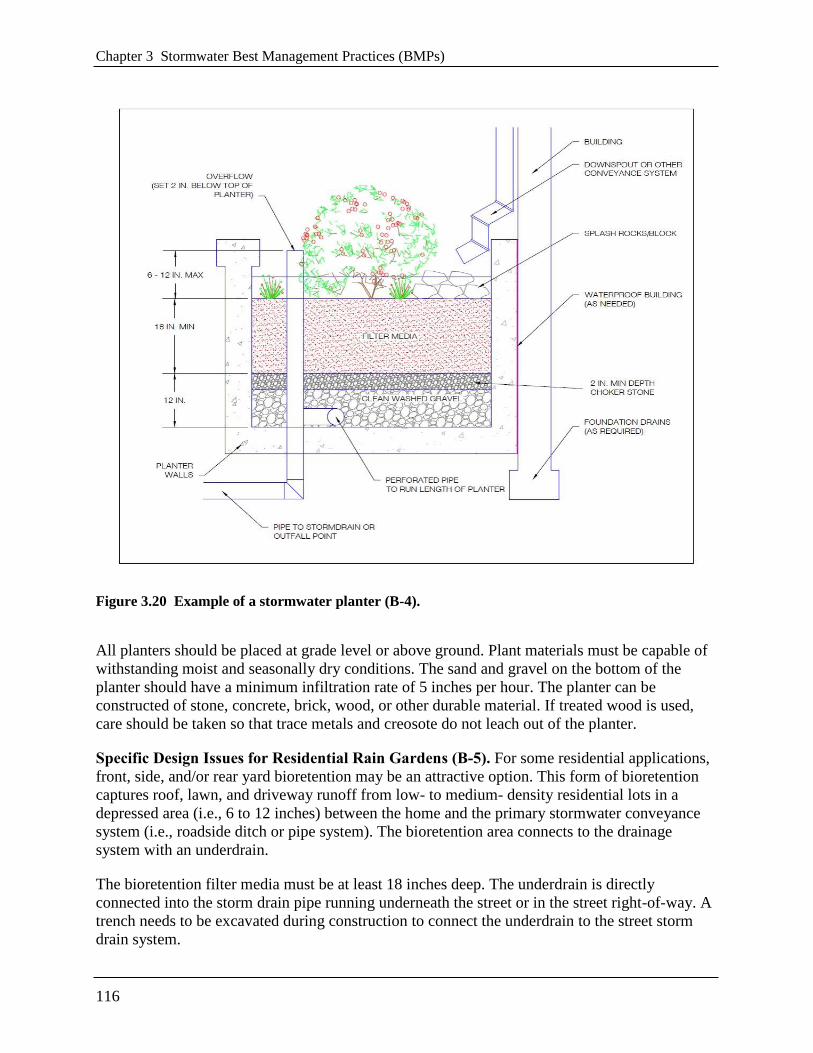
Chapter 3 Stormwater Best Management Practices (BMPs)
116
Figure 3.20 Example of a stormwater planter (B-4).
All planters should be placed at grade level or above ground. Plant materials must be capable of
withstanding moist and seasonally dry conditions. The sand and gravel on the bottom of the
planter should have a minimum infiltration rate of 5 inches per hour. The planter can be
constructed of stone, concrete, brick, wood, or other durable material. If treated wood is used,
care should be taken so that trace metals and creosote do not leach out of the planter.
Specific Design Issues for Residential Rain Gardens (B-5). For some residential applications,
front, side, and/or rear yard bioretention may be an attractive option. This form of bioretention
captures roof, lawn, and driveway runoff from low- to medium- density residential lots in a
depressed area (i.e., 6 to 12 inches) between the home and the primary stormwater conveyance
system (i.e., roadside ditch or pipe system). The bioretention area connects to the drainage
system with an underdrain.
The bioretention filter media must be at least 18 inches deep. The underdrain is directly
connected into the storm drain pipe running underneath the street or in the street right-of-way. A
trench needs to be excavated during construction to connect the underdrain to the street storm
drain system.

3.6 Bioretention
117
Construction of the remainder of the bioretention system is deferred until after the lot has been
stabilized. Residential rain gardens require regular maintenance to perform effectively.
BMP Sizing. Bioretention is typically sized to capture the SWRv or larger design storm volumes
in the surface ponding area, soil media, and gravel reservoir layers of the BMP.
Total storage volume of the BMP is calculated using Equation 3.5.
Equation 3.5 Bioretention Storage Volume
)(][ pondingaveragegravelgravelmediamediabottom dSAddSASv
where:
Sv = total storage volume of bioretention (ft3)
SAbottom = bottom surface area of bioretention (ft2)
dmedia = depth of the filter media (ft)
ηmedia = effective porosity of the filter media (typically 0.25)
dgravel = depth of the underdrain and underground storage gravel layer (ft)
ηgravel = effective porosity of the gravel layer (typically 0.4)
SAaverage = average surface area of bioretention (ft2)
typically, where SAtop is the top surface area of bioretention,
2
topbottom
average
SASASA
dponding = maximum ponding depth of bioretention (ft)
Equation 3.5 can be modified if the storage depths of the filter media, gravel layer, or ponded
water vary in the actual design or with the addition of any surface or subsurface storage
components (e.g., additional area of surface ponding, subsurface storage chambers, etc.). The
maximum depth of ponding in the bioretention must not exceed 18 inches. If storage practices
will be provided off-line or in series with the bioretention area, the storage practices should be
sized using the guidance in Section 3.12.
Bioretention can be designed to address, in whole or in part, the detention storage needed to
comply with channel protection and/or flood control requirements. The Sv can be counted as part
of the 2-year or 15-year runoff volumes to satisfy stormwater quantity control requirements. At
least 3–6 inches of freeboard are required between the top of the overflow device and the top of
the bioretention area when bioretention is used as detention storage for 2-year and 15-year
storms.
Note: In order to increase the storage volume of a bioretention area, the ponding surface area
may be increased beyond the filter media surface area. However, the top surface area of the
practice (i.e., at the top of the ponding elevation) may not be more than twice the size of the
surface area of the filter media (SAbottom).
Chapter 3 Stormwater Best Management Practices (BMPs)
118
3.6.5 Bioretention Landscaping Criteria
Landscaping is critical to the performance and function of bioretention areas. Therefore, a
landscaping plan shall be provided for bioretention areas.
Minimum plan elements include the proposed bioretention template to be used, delineation of
planting areas, and the planting plan including the following:
Common and botanical names of the plants used
Size of planted materials
Mature size of the plants
Light requirements
Maintenance requirements
Source of planting stock
Any other specifications
Planting sequence
It is recommended that the planting plan be prepared by a qualified landscape architect
professional (e.g. licensed professional landscape architect, certified horticulturalist) in order to
tailor the planting plan to the site-specific conditions.
Native plant species are preferred over non-native species, but some ornamental species may be
used for landscaping effect if they are not aggressive or invasive. Some popular native species
that work well in bioretention areas and are commercially available can be found in Table 3.23
and Table 3.24. Internet links to more detailed bioretention plant lists developed in the
Chesapeake Bay region are provided below:
Prince Georges County, MD
http://www.aacounty.org/DPW/Highways/Resources/Raingarden/RG_Bioretention_PG%20
CO.pdf
Delaware Green Technology Standards and Specifications
http://www.dnrec.state.de.us/DNREC2000/Divisions/Soil/Stormwater/New/GT_Stds%20&%
20Specs_06-05.pdf
The degree of landscape maintenance that can be provided will determine some of the planting
choices for urban bioretention areas. Plant selection differs if the area will be frequently mowed,
pruned, and weeded, in contrast to a site which will receive minimum annual maintenance. In
areas where less maintenance will be provided and where trash accumulation in shrubbery or
herbaceous plants is a concern, consider a ―turf and trees‖ landscaping model where the turf is
mowed along with other turf areas on the site. Spaces for herbaceous flowering plants can be
included.
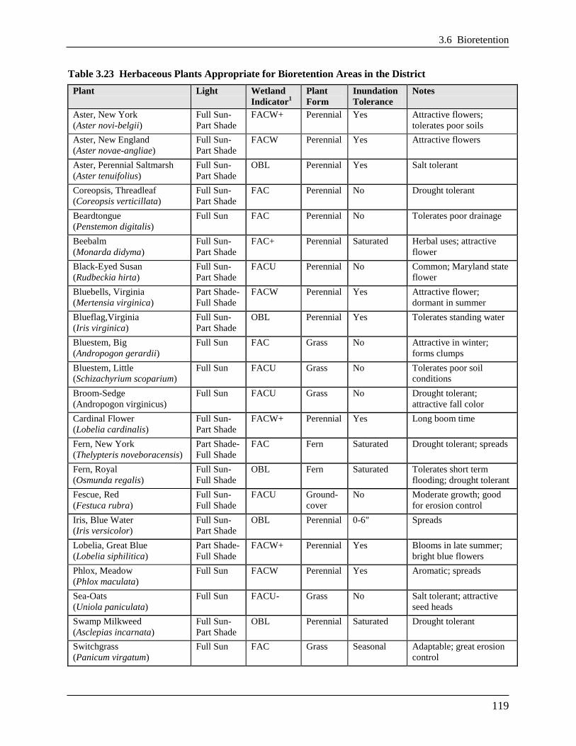
3.6 Bioretention
119
Table 3.23 Herbaceous Plants Appropriate for Bioretention Areas in the District
Plant Light Wetland
Indicator1
Plant
Form
Inundation
Tolerance
Notes
Aster, New York
(Aster novi-belgii)
Full Sun-
Part Shade
FACW+ Perennial Yes Attractive flowers;
tolerates poor soils
Aster, New England
(Aster novae-angliae)
Full Sun-
Part Shade
FACW Perennial Yes Attractive flowers
Aster, Perennial Saltmarsh
(Aster tenuifolius)
Full Sun-
Part Shade
OBL Perennial Yes Salt tolerant
Coreopsis, Threadleaf
(Coreopsis verticillata)
Full Sun-
Part Shade
FAC Perennial No Drought tolerant
Beardtongue
(Penstemon digitalis)
Full Sun FAC Perennial No Tolerates poor drainage
Beebalm
(Monarda didyma)
Full Sun-
Part Shade
FAC+ Perennial Saturated Herbal uses; attractive
flower
Black-Eyed Susan
(Rudbeckia hirta)
Full Sun-
Part Shade
FACU Perennial No Common; Maryland state
flower
Bluebells, Virginia
(Mertensia virginica)
Part Shade-
Full Shade
FACW Perennial Yes Attractive flower;
dormant in summer
Blueflag,Virginia
(Iris virginica)
Full Sun-
Part Shade
OBL Perennial Yes Tolerates standing water
Bluestem, Big
(Andropogon gerardii)
Full Sun FAC Grass No Attractive in winter;
forms clumps
Bluestem, Little
(Schizachyrium scoparium)
Full Sun FACU Grass No Tolerates poor soil
conditions
Broom-Sedge
(Andropogon virginicus)
Full Sun FACU Grass No Drought tolerant;
attractive fall color
Cardinal Flower
(Lobelia cardinalis)
Full Sun-
Part Shade
FACW+ Perennial Yes Long boom time
Fern, New York
(Thelypteris noveboracensis)
Part Shade-
Full Shade
FAC Fern Saturated Drought tolerant; spreads
Fern, Royal
(Osmunda regalis)
Full Sun-
Full Shade
OBL Fern Saturated Tolerates short term
flooding; drought tolerant
Fescue, Red
(Festuca rubra)
Full Sun-
Full Shade
FACU Ground-
cover
No Moderate growth; good
for erosion control
Iris, Blue Water
(Iris versicolor)
Full Sun-
Part Shade
OBL Perennial 0-6" Spreads
Lobelia, Great Blue
(Lobelia siphilitica)
Part Shade-
Full Shade
FACW+ Perennial Yes Blooms in late summer;
bright blue flowers
Phlox, Meadow
(Phlox maculata)
Full Sun FACW Perennial Yes Aromatic; spreads
Sea-Oats
(Uniola paniculata)
Full Sun FACU- Grass No Salt tolerant; attractive
seed heads
Swamp Milkweed
(Asclepias incarnata)
Full Sun-
Part Shade
OBL Perennial Saturated Drought tolerant
Switchgrass
(Panicum virgatum)
Full Sun FAC Grass Seasonal Adaptable; great erosion
control
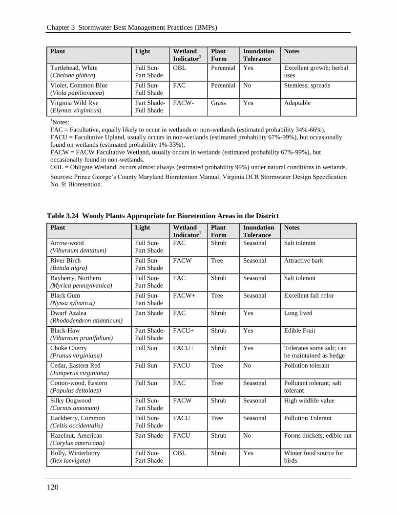
Chapter 3 Stormwater Best Management Practices (BMPs)
120
Plant Light Wetland
Indicator1
Plant
Form
Inundation
Tolerance
Notes
Turtlehead, White
(Chelone glabra)
Full Sun-
Part Shade
OBL Perennial Yes Excellent growth; herbal
uses
Violet, Common Blue
(Viola papilionacea)
Full Sun-
Full Shade
FAC Perennial No Stemless; spreads
Virginia Wild Rye
(Elymus virginicus)
Part Shade-
Full Shade
FACW- Grass Yes Adaptable
1Notes:
FAC = Facultative, equally likely to occur in wetlands or non-wetlands (estimated probability 34%-66%).
FACU = Facultative Upland, usually occurs in non-wetlands (estimated probability 67%-99%), but occasionally
found on wetlands (estimated probability 1%-33%).
FACW = FACW Facultative Wetland, usually occurs in wetlands (estimated probability 67%-99%), but
occasionally found in non-wetlands.
OBL = Obligate Wetland, occurs almost always (estimated probability 99%) under natural conditions in wetlands.
Sources: Prince George’s County Maryland Bioretention Manual; Virginia DCR Stormwater Design Specification
No. 9: Bioretention.
Table 3.24 Woody Plants Appropriate for Bioretention Areas in the District
Plant Light Wetland
Indicator1
Plant
Form
Inundation
Tolerance
Notes
Arrow-wood
(Viburnum dentatum)
Full Sun-
Part Shade
FAC Shrub Seasonal Salt tolerant
River Birch
(Betula nigra)
Full Sun-
Part Shade
FACW Tree Seasonal Attractive bark
Bayberry, Northern
(Myrica pennsylvanica)
Full Sun-
Part Shade
FAC Shrub Seasonal Salt tolerant
Black Gum
(Nyssa sylvatica)
Full Sun-
Part Shade
FACW+ Tree Seasonal Excellent fall color
Dwarf Azalea
(Rhododendron atlanticum)
Part Shade FAC Shrub Yes Long lived
Black-Haw
(Viburnum prunifolium)
Part Shade-
Full Shade
FACU+ Shrub Yes Edible Fruit
Choke Cherry
(Prunus virginiana)
Full Sun FACU+ Shrub Yes Tolerates some salt; can
be maintained as hedge
Cedar, Eastern Red
(Juniperus virginiana)
Full Sun FACU Tree No Pollution tolerant
Cotton-wood, Eastern
(Populus deltoides)
Full Sun FAC Tree Seasonal Pollutant tolerant; salt
tolerant
Silky Dogwood
(Cornus amomum)
Full Sun-
Part Shade
FACW Shrub Seasonal High wildlife value
Hackberry, Common
(Celtis occidentalis)
Full Sun-
Full Shade
FACU Tree Seasonal Pollution Tolerant
Hazelnut, American
(Corylus americana)
Part Shade FACU Shrub No Forms thickets; edible nut
Holly, Winterberry
(Ilex laevigata)
Full Sun-
Part Shade
OBL Shrub Yes Winter food source for
birds
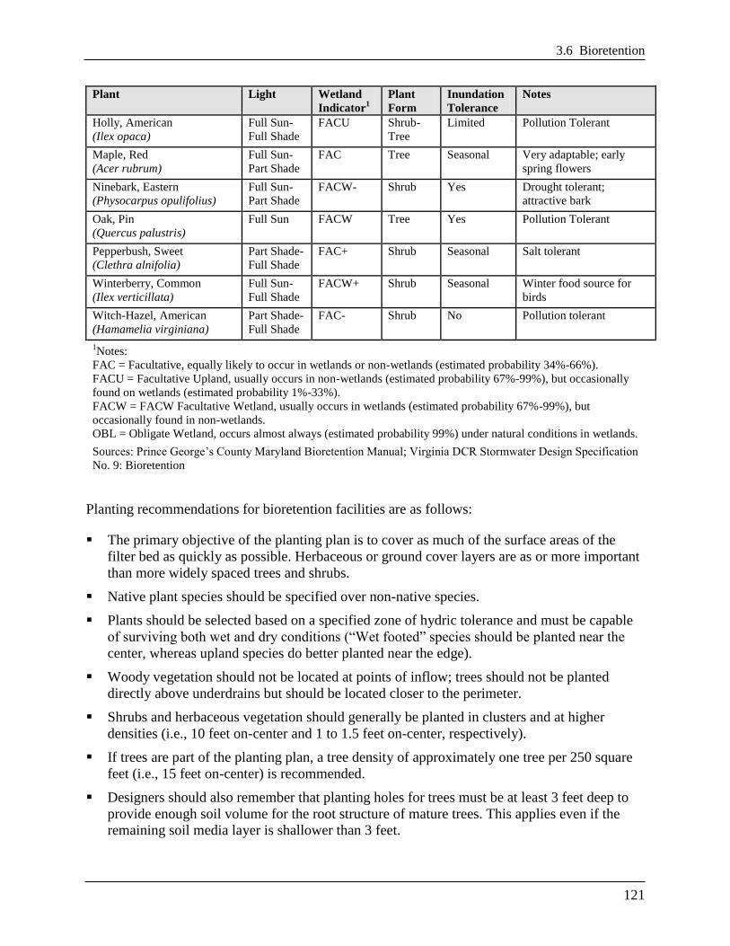
3.6 Bioretention
121
Plant Light Wetland
Indicator1
Plant
Form
Inundation
Tolerance
Notes
Holly, American
(Ilex opaca)
Full Sun-
Full Shade
FACU Shrub-
Tree
Limited Pollution Tolerant
Maple, Red
(Acer rubrum)
Full Sun-
Part Shade
FAC Tree Seasonal Very adaptable; early
spring flowers
Ninebark, Eastern
(Physocarpus opulifolius)
Full Sun-
Part Shade
FACW- Shrub Yes Drought tolerant;
attractive bark
Oak, Pin
(Quercus palustris)
Full Sun FACW Tree Yes Pollution Tolerant
Pepperbush, Sweet
(Clethra alnifolia)
Part Shade-
Full Shade
FAC+ Shrub Seasonal Salt tolerant
Winterberry, Common
(Ilex verticillata)
Full Sun-
Full Shade
FACW+ Shrub Seasonal Winter food source for
birds
Witch-Hazel, American
(Hamamelia virginiana)
Part Shade-
Full Shade
FAC- Shrub No Pollution tolerant
1Notes:
FAC = Facultative, equally likely to occur in wetlands or non-wetlands (estimated probability 34%-66%).
FACU = Facultative Upland, usually occurs in non-wetlands (estimated probability 67%-99%), but occasionally
found on wetlands (estimated probability 1%-33%).
FACW = FACW Facultative Wetland, usually occurs in wetlands (estimated probability 67%-99%), but
occasionally found in non-wetlands.
OBL = Obligate Wetland, occurs almost always (estimated probability 99%) under natural conditions in wetlands.
Sources: Prince George’s County Maryland Bioretention Manual; Virginia DCR Stormwater Design Specification
No. 9: Bioretention
Planting recommendations for bioretention facilities are as follows:
The primary objective of the planting plan is to cover as much of the surface areas of the
filter bed as quickly as possible. Herbaceous or ground cover layers are as or more important
than more widely spaced trees and shrubs.
Native plant species should be specified over non-native species.
Plants should be selected based on a specified zone of hydric tolerance and must be capable
of surviving both wet and dry conditions (―Wet footed‖ species should be planted near the
center, whereas upland species do better planted near the edge).
Woody vegetation should not be located at points of inflow; trees should not be planted
directly above underdrains but should be located closer to the perimeter.
Shrubs and herbaceous vegetation should generally be planted in clusters and at higher
densities (i.e., 10 feet on-center and 1 to 1.5 feet on-center, respectively).
If trees are part of the planting plan, a tree density of approximately one tree per 250 square
feet (i.e., 15 feet on-center) is recommended.
Designers should also remember that planting holes for trees must be at least 3 feet deep to
provide enough soil volume for the root structure of mature trees. This applies even if the
remaining soil media layer is shallower than 3 feet.

Chapter 3 Stormwater Best Management Practices (BMPs)
122
Tree species should be those that are known to survive well in the compacted soils and the
polluted air and water of an urban landscape.
If trees are used, plant shade-tolerant ground covers within the drip line.
If the bioretention area is to be used for snow storage or is to accept snowmelt runoff, it
should be planted with salt-tolerant, herbaceous perennials.
3.6.6 Bioretention Construction Sequence
Soil Erosion and Sediment Controls. The following soil erosion and sediment control
guidelines must be followed during construction:
All Bioretention areas must be fully protected by silt fence or construction fencing.
Bioretention areas intended to infiltrate runoff must remain outside the limit of disturbance
during construction to prevent soil compaction by heavy equipment and loss of design
infiltration rate.
Where it is infeasible keep the proposed bioretention areas outside of the limits of
disturbance, there are several possible outcomes for the impacted area. If excavation in
the proposed bioretention area can be restricted then the remediation can be achieved
with deep tilling practices. This is only possible if in-situ soils are not disturbed any
deeper than 2 feet above the final design elevation of the bottom of the bioretention. In
this case, when heavy equipment activity has ceased, the area is excavated to grade, and
the impacted area must be tilled to a depth of 12 inches below the bottom of the
bioretention.
Alternatively, if it is infeasible to keep the proposed permeable pavement areas outside of
the limits of disturbance, and excavation of the area cannot be restricted, then infiltration
tests will be required prior to installation of the bioretention to ensure that the design
infiltration rate is still present. If tests reveal the loss of design infiltration rates then deep
tilling practices may be used in an effort to restore those rates. In this case further testing
must be done to establish design rates exist before the permeable pavement can be
installed.
Finally, if it is infeasible to keep the proposed bioretention areas outside of the limits of
disturbance, and excavation of the area cannot be restricted, and infiltration tests reveal
design rates cannot be restored, then a resubmission of the SWMP will be required.
Bioretention areas must be clearly marked on all construction documents and grading plans.
Large bioretention applications may be used as small sediment traps or basins during
construction. However, these must be accompanied by notes and graphic details on the soil
erosion and sediment control plan specifying that (1) the maximum excavation depth of the
trap or basin at the construction stage must be at least 1 foot higher than the post-construction
(final) invert (bottom of the facility), and (2) the facility must contain an underdrain. The
plan must also show the proper procedures for converting the temporary sediment control
practice to a permanent bioretention BMP, including dewatering, cleanout, and stabilization.

3.6 Bioretention
123
Bioretention Installation. The following is a typical construction sequence to properly install a
bioretention basin. The construction sequence for micro-bioretention is more simplified. These
steps may be modified to reflect different bioretention applications or expected site conditions:
Step 1: Stabilize Drainage Area. Construction of the bioretention area may only begin after
the entire contributing drainage area has been stabilized with vegetation. It may be necessary to
block certain curb or other inlets while the bioretention area is being constructed. The proposed
site should be checked for existing utilities prior to any excavation.
Step 2: Preconstruction Meeting. The designer, the installer, and DDOE inspector must
have a preconstruction meeting, checking the boundaries of the contributing drainage area and
the actual inlet elevations to ensure they conform to original design. Since other contractors may
be responsible for constructing portions of the site, it is quite common to find subtle differences
in site grading, drainage and paving elevations that can produce hydraulically important
differences for the proposed bioretention area. The designer should clearly communicate, in
writing, any project changes determined during the preconstruction meeting to the installer and
the inspector. Material certifications for aggregate, soil media and any geotextiles must be
submitted for approval to the inspector at the preconstruction meeting.
Step 3: Install Soil Erosion and Sediment Control Measures to Protect the Bioretention. Temporary soil erosion and sediment controls (e.g., diversion dikes, reinforced silt fences) are
needed during construction of the bioretention area to divert stormwater away from the
bioretention area until it is completed. Special protection measures, such as erosion control
fabrics, may be needed to protect vulnerable side slopes from erosion during the construction
process.
Step 4: Install Pretreatment Cells. Any pretreatment cells should be excavated first and
then sealed to trap sediment.
Step 5: Avoid Impact of Heavy Installation Equipment. Excavators or backhoes should
work from the sides to excavate the bioretention area to its appropriate design depth and
dimensions. Excavating equipment should have scoops with adequate reach so they do not have
to sit inside the footprint of the bioretention area. Contractors should use a cell construction
approach in larger bioretention basins, whereby the basin is split into 500- to 1,000-square foot
temporary cells with a 10- to15-foot earth bridge in between, so that cells can be excavated from
the side.
Step 6: Promote Infiltration Rate. It may be necessary to rip the bottom soils to a depth of 6
to 12 inches to promote greater infiltration.
Step 7: Order of Materials. If using a geotextile fabric, place the fabric on the sides of the
bioretention area with a 6-inch overlap on the sides. If a stone storage layer will be used, place
the appropriate depth of No. 57 stone (clean double washed) on the bottom, install the perforated
underdrain pipe, pack No. 57 stone to 3 inches above the underdrain pipe, and add the choking
layer or appropriate geotextile layer as a filter between the underdrain and the soil media layer. If
no stone storage layer is used, start with 6 inches of No. 57 stone on the bottom and proceed with
the layering as described above.
Step 8: Layered Installation of Media. Apply the media in 12-inch lifts until the desired top
elevation of the bioretention area is achieved. Wait a few days to check for settlement and add
additional media, as needed, to achieve the design elevation.
Chapter 3 Stormwater Best Management Practices (BMPs)
124
Note: The batch receipt confirming the source of the soil media must be submitted to the DDOE
inspector.
Step 9: Prepare Filter Media for Plants. Prepare planting holes for any trees and shrubs,
install the vegetation, and water accordingly. Install any temporary irrigation.
Step 10: Planting. Install the plant materials as shown in the landscaping plan, and water them
as needed.
Step 11: Secure Surface Area. Place the surface cover (i.e., mulch, river stone, or turf) in both
cells, depending on the design. If coir or jute matting will be used in lieu of mulch, the matting
will need to be installed prior to planting (Step 10), and holes or slits will have to be cut in the
matting to install the plants.
Step 12: Inflows. If curb cuts or inlets are blocked during bioretention installation, unblock
these after the drainage area and side slopes have good vegetative cover. It is recommended that
unblocking curb cuts and inlets take place after two to three storm events if the drainage area
includes newly installed asphalt, since new asphalt tends to produce a lot of fines and grit during
the first several storms.
Step 13: Final Inspection. Conduct the final construction inspection using a qualified
professional, providing DDOE with an as-built, then log the GPS coordinates for each
bioretention facility, and submit them for entry into the maintenance tracking database.
Construction Supervision. Supervision during construction is recommended to ensure that the
bioretention area is built in accordance with the approved design and this specification. Qualified
individuals should use detailed inspection checklists that include sign-offs at critical stages of
construction, to ensure that the contractor’s interpretation of the plan is consistent with the
designer’s intentions.
DDOE’s construction phase inspection checklist can be found in Appendix K.
3.6.7 Bioretention Maintenance Criteria
When bioretention practices are installed, it is the owner’s responsibility to ensure they, or those
managing the practice, (1) be educated about their routine maintenance needs, (2) understand the
long-term maintenance plan, and (3) be subject to a maintenance covenant or agreement, as
described below.
Maintenance of bioretention areas should be integrated into routine landscape maintenance tasks.
If landscaping contractors will be expected to perform maintenance, their contracts should
contain specifics on unique bioretention landscaping needs, such as maintaining elevation
differences needed for ponding, proper mulching, sediment and trash removal, and limited use of
fertilizers and pesticides.
Maintenance tasks and frequency will vary depending on the size and location of the
bioretention, the landscaping template chosen, and the type of surface cover in the practice. A
generalized summary of common maintenance tasks and their frequency is provided in Table
3.25.

3.6 Bioretention
125
Table 3.25 Typical Maintenance Tasks for Bioretention Practices
Frequency Maintenance Tasks
Upon establishment
For the first 6 months following construction, the practice and CDA should be
inspected at least twice after storm events that exceed 1/2 inch of rainfall.
Conduct any needed repairs or stabilization.
Inspectors should look for bare or eroding areas in the contributing drainage
area or around the bioretention area, and make sure they are immediately
stabilized with grass cover.
One-time, spot fertilization may be needed for initial plantings.
Watering is needed once a week during the first 2 months, and then as needed
during first growing season (April-October), depending on rainfall.
Remove and replace dead plants. Up to 10% of the plant stock may die off in
the first year, so construction contracts should include a care and replacement
warranty to ensure that vegetation is properly established and survives during
the first growing season following construction.
At least 4 times per year
Mow grass filter strips and bioretention with turf cover
Check curb cuts and inlets for accumulated grit, leaves, and debris that may
block inflow
Twice during growing season Spot weed, remove trash, and rake the mulch
Annually
Conduct a maintenance inspection
Supplement mulch in devoid areas to maintain a 3 inch layer
Prune trees and shrubs
Remove sediment in pretreatment cells and inflow points
Once every 2–3 years Remove sediment in pretreatment cells and inflow points
Remove and replace the mulch layer
As needed
Add reinforcement planting to maintain desired vegetation density
Remove invasive plants using recommended control methods
Remove any dead or diseased plants
Stabilize the contributing drainage area to prevent erosion
Standing water is the most common problem outside of routine maintenance. If water remains on
the surface for more than 72 hours after a storm, adjustments to the grading may be needed or
underdrain repairs may be needed. The surface of the filter bed should also be checked for
accumulated sediment or a fine crust that builds up after the first several storm events. There are
several methods that can be used to rehabilitate the filter. These are listed below, starting with
the simplest approach and ranging to more involved procedures (i.e., if the simpler actions do not
solve the problem):
Open the underdrain observation well or cleanout and pour in water to verify that the
underdrains are functioning and not clogged or otherwise in need of repair. The purpose of
this check is to see if there is standing water all the way down through the soil. If there is
standing water on top, but not in the underdrain, then there is a clogged soil layer. If the
underdrain and stand pipe indicates standing water, then the underdrain must be clogged and
will need to be cleaned out.
Remove accumulated sediment and till 2 to 3 inches of sand into the upper 6 to 12 inches of
soil.

Chapter 3 Stormwater Best Management Practices (BMPs)
126
Install sand wicks from 3 inches below the surface to the underdrain layer. This reduces the
average concentration of fines in the media bed and promotes quicker drawdown times. Sand
wicks can be installed by excavating or auguring (i.e., using a tree auger or similar tool)
down to the top of the underdrain layer to create vertical columns which are then filled with a
clean open-graded coarse sand material (e.g., ASTM C-33 concrete sand or similar approved
sand mix for bioretention media). A sufficient number of wick drains of sufficient dimension
should be installed to meet the design dewatering time for the facility.
Remove and replace some or all of the soil media.
Maintenance Inspections. It is recommended that a qualified professional conduct a spring
maintenance inspection and cleanup at each bioretention area. Maintenance inspections should
include information about the inlets, the actual bioretention facility (sediment buildup, outlet
conditions, etc.), and the state of vegetation (water stressed, dead, etc.) and are intended to
highlight any issues that need or may need attention to maintain stormwater management
functionality.
DDOE’s maintenance inspection checklists for bioretention areas and the Maintenance Service
Completion Inspection form can be found in Appendix L.
Declaration of Covenants. A declaration of covenants that includes all maintenance
responsibilities to ensure the continued stormwater performance for the BMP is required. The
declaration of covenants specifies the property owner’s primary maintenance responsibilities,
and authorizes DDOE staff to access the property for inspection or corrective action in the event
the proper maintenance is not performed. The declaration of covenants is attached to the deed of
the property. A template form is provided at the end of Chapter 5 (see Figure 5.4), although
variations will exist for scenarios where stormwater crosses property lines. The covenant is
between the property and the Government of the District of Columbia. It is submitted through the
Office of the Attorney General. All SWMPs have a maintenance agreement stamp that must be
signed for a building permit to proceed. A maintenance schedule must appear on the SWMP.
Additionally, a maintenance schedule is required in Exhibit C of the declaration of covenants.
Covenants are not required on government properties, but maintenance responsibilities must be
defined through a partnership agreement or a memorandum of understanding.
Waste Material. Waste material from the repair, maintenance, or removal of a BMP or land
cover shall be removed and disposed of in compliance with applicable federal and District law.
3.6.8 Bioretention Stormwater Compliance Calculations
Bioretention performance varies depending on the design configuration of the system.
Enhanced Designs. These designs are bioretention applications with no underdrain or at least 24
inches of filter media and an infiltration sump. Enhanced designs receive 100 percent retention
value for the amount of storage volume (Sv) provided by the practice (Table 3.26), and,
therefore, are not considered an accepted total suspended solids (TSS) treatment practice.

3.6 Bioretention
127
Table 3.26 Enhanced Bioretention Retention Value and Pollutant Removal
Retention Value = Sv
Accepted TSS Treatment Practice N/A
Standard Designs. These designs are bioretention applications with an underdrain and less than
24 inches of filter media. Standard designs receive 60 percent retention value and are an accepted
TSS removal practice for the amount of storage volume (Sv) provided by the practice (Table
3.27).
Table 3.27 Standard Bioretention Design Retention Value and Pollutant Removal
Retention Value = 0.6 × Sv
Accepted TSS Treatment Practice Yes
The practice must be sized using the guidance detailed in Section 3.6.4.
Note: Additional retention value can be achieved if trees are utilized as part of a bioretention area
(see Section 3.2.3 Green Roof Pretreatment Criteria).
Bioretention also contributes to peak flow reduction. This contribution can be determined in
several ways. One method is to subtract the Sv or Rv from the total runoff volume for the 2-year,
15-year, and 100-year storms. The resulting reduced runoff volumes can then be used to
calculate a Reduced Natural Resource Conservation Service (NRCS) Curve Number for the site
or drainage area. The Reduced Curve Number can then be used to calculate peak flow rates for
the various storm events. Other hydrologic modeling tools that employ different procedures may
be used as well.
3.6.9 References
Cappiella, K., T. Schueler and T. Wright. 2006. Urban Watershed Forestry Manual: Part 2:
Conserving and Planting Trees at Development Sites. USDA Forest Service. Center for
Watershed Protection. Ellicott City, MD.
CWP. 2007. National Pollutant Removal Performance Database, Version 3.0. Center for
Watershed Protection, Ellicott City, MD.
Hirschman, D., L. Woodworth and S. Drescher. 2009. Technical Report: Stormwater BMPs in
Virginia’s James River Basin – An Assessment of Field Conditions and Programs. Center for
Watershed Protection. Ellicott City, MD.
Hunt, W.F. III and W.G. Lord. 2006. ―Bioretention Performance, Design, Construction, and
Maintenance.‖ North Carolina Cooperative Extension Service Bulletin. Urban Waterways
Series. AG-588-5. North Carolina State University. Raleigh, NC.

Chapter 3 Stormwater Best Management Practices (BMPs)
128
Maryland Department of the Environment. 2001. Maryland Stormwater Design Manual.
http://www.mde.state.md.us/programs/Water/StormwaterManagementProgram/MarylandStor
mwaterDesignManual/Pages/Programs/WaterPrograms/SedimentandStormwater/stormwater
_design/index.aspx
Prince George’s Co., MD. 2007. Bioretention Manual. Available online at:
http://www.princegeorgescountymd.gov/Government/AgencyIndex/DER/ESG/Bioretention/
pdf/Bioretention%20Manual_2009%20Version.pdf
Saxton, K.E., W.J. Rawls, J.S. Romberger, and R.I. Papendick. 1986. ―Estimating generalized
soil-water characteristics from texture.‖ Soil Sci. Soc. Am. J. 50(4):1031-1036.Schueler, T.
2008. Technical Support for the Baywide Runoff Reduction Method. Chesapeake
Stormwater Network. Baltimore, MD. www.chesapeakestormwater.net
Smith, R.A. and Hunt, W.F. III. 1999. ―Pollutant Removal in Bioretention Cells with Grass
Cover‖
Smith, R. A., and Hunt, W.F. III. 2007. ―Pollutant removal in bioretention cells with grass
cover.‖ Pp. 1-11 In: Proceedings of the World Environmental and Water Resources Congress
2007.
Sumner, M. E. and W. P. Miller. 1996. Cation Exchange Capacity and Exchange Coefficients.
Methods of Soil Analysis, Part 3 – Chemical Methods: 1201-1229
Virginia DCR Stormwater Design Specification No. 9: Bioretention Version 1.8. 2010.
Wisconsin Department of Natural Resources. Storm Water Post-Construction Technical
Standards. http://dnr.wi.gov/topic/stormwater/standards/postconst_standards.html
3.7 Filtering Systems
129
3.7 Filtering Systems
Definition. Practices that capture and temporarily store the design storm volume and pass it
through a filter bed of sand media. Filtered runoff may be collected and returned to the
conveyance system or allowed to partially infiltrate into the soil. Design variants include:
F-1 Non-structural sand filter
F-2 Surface sand filter
F-3 Three-chamber underground sand filter
F-4 Perimeter sand filter
Stormwater filters are a useful practice to treat stormwater runoff from small, highly impervious
sites. Stormwater filters capture, temporarily store, and treat stormwater runoff by passing it
through an engineered filter media, collecting the filtered water in an underdrain, and then
returning it back to the storm drainage system. The filter consists of two chambers: the first is
devoted to settling and the second serves as a filter bed consisting of a sand filter media.
Stormwater filters are a versatile option because they consume very little surface land and have
few site restrictions. They provide moderate pollutant removal performance at small sites where
space is limited. However, filters have no retention capability, so designers should consider using
up-gradient retention practices, which have the effect of decreasing the design storm volume and
size of the filtering practices. Filtering practices are also suitable to provide special treatment at
designated stormwater hotspots. A list of potential stormwater hotspots operations can be found
in Appendix P.
Filtering systems are typically not to be designed to provide stormwater detention (Qp2, Qp15),
but they may be in some circumstances. Filtering practices are generally combined with separate
facilities to provide this type of control. However, the three-chamber underground sand filter can
be modified by expanding the first or settling chamber, or adding an extra chamber between the
filter chamber and the clear well chamber to handle the detention volume, which is subsequently
discharged at a predetermined rate through an orifice and weir combination.

Chapter 3 Stormwater Best Management Practices (BMPs)
130
Figure 3.21 Typical schematic for a surface sand filter (F-2).
Note: Material specifications are indicated in Table 3.28.
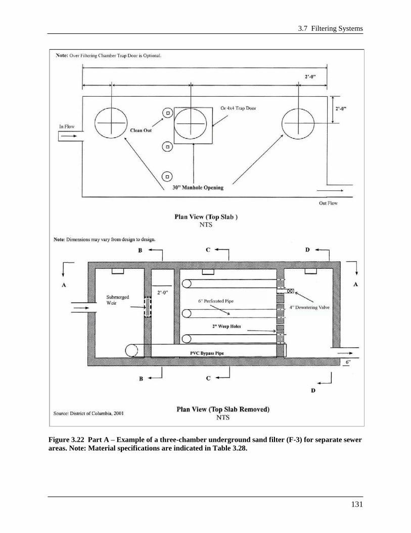
3.7 Filtering Systems
131
Figure 3.22 Part A – Example of a three-chamber underground sand filter (F-3) for separate sewer
areas. Note: Material specifications are indicated in Table 3.28.

Chapter 3 Stormwater Best Management Practices (BMPs)
132
Figure 3.23 Part B – Example of a three-chamber underground sand filter (F-3) for separate sewer
areas. Note: Material specifications are indicated in Table 3.28.
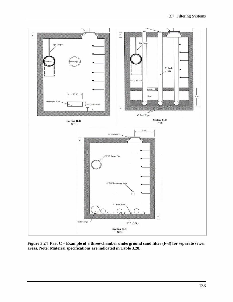
3.7 Filtering Systems
133
Figure 3.24 Part C – Example of a three-chamber underground sand filter (F-3) for separate sewer
areas. Note: Material specifications are indicated in Table 3.28.

Chapter 3 Stormwater Best Management Practices (BMPs)
134
Figure 3.25 Part A – Example of a three-chamber underground sand filter (F-3) for combined
sewer areas. Note: Material specifications are indicated in Table 3.28.

3.7 Filtering Systems
135
Figure 3.26 Part B – Example of a three-chamber underground sand filter (F-3) for combined
sewer areas. Note: Material specifications are indicated in Table 3.28.

Chapter 3 Stormwater Best Management Practices (BMPs)
136
Figure 3.27 Part C – Example of a three-chamber underground sand filter (F-3) for combined
sewer areas. Note: Material specifications are indicated in Table 3.28.

3.7 Filtering Systems
137
Figure 3.28 Example of a perimeter sand filter (F-4).
Note: Material specifications are indicated in Table 3.28.
Chapter 3 Stormwater Best Management Practices (BMPs)
138
3.7.1 Filtering Feasibility Criteria
Stormwater filters can be applied to most types of urban land. They are not always cost-effective,
given their high unit cost and small area served, but there are situations where they may clearly
be the best option for stormwater treatment (e.g., hotspot runoff treatment, small parking lots,
ultra-urban areas, etc.). The following criteria apply to filtering practices:
Available Hydraulic Head. The principal design constraint for stormwater filters is available
hydraulic head, which is defined as the vertical distance between the top elevation of the filter
and the bottom elevation of the existing storm drain system that receives its discharge. The head
required for stormwater filters ranges from 2 to 10 feet, depending on the design variant. It is
difficult to employ filters in extremely flat terrain, since they require gravity flow through the
filter. The only exception is the perimeter sand filter, which can be applied at sites with as little
as 2 feet of head.
Depth to Water Table and Bedrock. The designer must assure a standard separation distance
of at least 2 feet between the seasonally high groundwater table and/or bedrock layer and the
bottom invert of the filtering practice.
Contributing Drainage Area. Filters are best applied on small sites where the contributing
drainage (CDA) area is as close to 100 percent impervious as possible in order to reduce the risk
that eroded sediment will clog the filter. If the CDA is pervious, then the vegetation must be
dense and stable. Turf is acceptable (see Section 3.7.5 Filtering Landscaping Criteria). A
maximum CDA of 5 acres is recommended for surface sand filters, and a maximum CDA of 2
acres is recommended for perimeter or underground filters. Filters have been used on larger
drainage areas in the past, but greater clogging problems have typically resulted. The one-
chamber sand filter is only applicable for impervious area less than 10,000 ft2 (1/4 acre).
Space Required. The amount of space required for a filter practice depends on the design
variant selected. Surface sand filters typically consume about 2 to 3 percent of the CDA, while
perimeter sand filters typically consume less than 1 percent. Underground stormwater filters
generally consume no surface area except their manholes.
Land Use. As noted above, filters are particularly well suited to treat runoff from stormwater
hotspots and smaller parking lots. Other applications include redevelopment of commercial sites
or when existing parking lots are renovated or expanded. Filters can work on most commercial,
industrial, institutional, or municipal sites and can be located underground if surface area is not
available.
Site Topography. Filters shall not be located on slopes greater than 6 percent.
Utilities. All utilities shall have a minimum 5-foot, horizontal clearance from the filtering
practice.
Facility Access. All filtering systems shall be located in areas where they are accessible for
inspection and for maintenance (by vacuum trucks).

3.7 Filtering Systems
139
Soils. Soil conditions do not constrain the use of filters. At least one soil boring must be taken at
a low point within the footprint of the proposed filtering practice to establish the water table and
bedrock elevations and evaluate soil suitability. A geotechnical investigation is required for all
underground stormwater best management practices (BMPs), including underground filtering
systems. Geotechnical testing requirements are outlined in Appendix O.
3.7.2 Filtering Conveyance Criteria
Most filtering practices are designed as off-line systems so that all flows enter the filter storage
chamber until it reaches capacity, at which point larger flows are then diverted or bypassed
around the filter to an outlet chamber and are not treated. Runoff from larger storm events must
be bypassed using an overflow structure or a flow splitter. Claytor and Schueler (1996) and ARC
(2001) provide design guidance for flow splitters for filtering practices.
Some underground filters will be designed and constructed as on-line BMPs. In these cases,
designers must indicate how the device will safely pass larger storm events (e.g., the 15-year
event) to a stabilized water course without resuspending or flushing previously trapped material.
All stormwater filters must be designed to drain or dewater within 72 hours after a storm event to
reduce the potential for nuisance conditions.
3.7.3 Filtering Pretreatment Criteria
Adequate pretreatment is needed to prevent premature filter clogging and ensure filter longevity.
Dry or wet pretreatment shall be provided prior to filter media. Pretreatment devices are subject
to the following criteria:
Sedimentation chambers are typically used for pretreatment to capture coarse sediment
particles before they reach the filter bed.
Sedimentation chambers may be wet or dry but must be sized to accommodate at least 25
percent of the total design storm volume (inclusive).
Sediment chambers should be designed as level spreaders such that inflows to the filter bed
have near zero velocity and spread runoff evenly across the bed.
Non-structural and surface sand filters may use alternative pretreatment measures, such as a
grass filter strip, forebay, gravel diaphragm, check dam, level spreader, or a combination of
these. The grass filter strip must be a minimum length of 15 feet and have a slope of 3
percent or less. The check dam may be wooden or concrete and must be installed so that it
extends only 2 inches above the filter strip and has lateral slots to allow runoff to be evenly
distributed across the filter surface. Alternative pretreatment measures must contain a non-
erosive flow path that distributes the flow evenly over the filter surface. If a forebay is used,
it must be designed to accommodate at least 25 percent of the total design storm volume
(inclusive).

Chapter 3 Stormwater Best Management Practices (BMPs)
140
3.7.4 Filtering Design Criteria
Detention time. All filter systems must be designed to drain the design storm volume from the
filter chamber within 72 hours after each rainfall event.
Structural Requirements. If a filter will be located underground or experience traffic loads, a
licensed structural engineer must certify the structural integrity of the design.
Geometry. Filters are gravity flow systems that normally require 2 to 5 feet of driving head to
push the water through the filter media through the entire maintenance cycle; therefore, sufficient
vertical clearance between the inverts of the inflow and outflow pipes is required.
Type of Filter Media. The normal filter media consists of clean, washed AASHTO M-6/ASTM
C-33 medium aggregate concrete sand with individual grains between 0.02 and 0.04 inches in
diameter.
Depth of Filter Media. The depth of the filter media plays a role in how quickly stormwater
moves through the filter bed and how well it removes pollutants. The recommended filter bed
depth is 18 inches. An absolute minimum filter bed depth of 12 inches above underdrains is
required; although, designers should note that specifying the minimum depth of 12 inches will
incur a more intensive maintenance schedule and possibly result in more costly maintenance.
Underdrain and Liner. Stormwater filters are normally designed with an impermeable liner and
underdrain system that meet the criteria provided in Table 3.28 below.
Underdrain Stone. The underdrain should be covered by a minimum 6-inch gravel layer
consisting of clean, double washed No. 57 stone.
Type of Filter. There are several design variations of the basic filter that enable designers to use
filters at challenging sites or to improve pollutant removal rates. The choice of which filter
design to apply depends on available space, hydraulic head, and the level of pollutant removal
desired. In ultra-urban situations where surface space is at a premium, underground sand filters
are often the only design that can be used. Surface and perimeter filters are often a more
economical choice when adequate surface area is available. The most common design variants
include the following:
Non-Structural Sand Filter (F-1). The non-structural sand filter is applied to sites less than
2 acres in size and is very similar to a bioretention practice (see Section 3.6 Bioretention),
with the following exceptions:
The bottom is lined with an impermeable liner and always has an underdrain.
The surface cover is sand, turf, or pea gravel.
The filter media is 100 percent sand.
The filter surface is not planted with trees, shrubs, or herbaceous materials.
The filter has two cells, with a dry or wet sedimentation chamber preceding the sand filter
bed.

3.7 Filtering Systems
141
The non-structural sand filter is the least expensive filter option for treating hotspot runoff.
The use of bioretention areas is generally preferred at most other sites.
Surface Sand Filter (F-2). The surface sand filter is designed with both the filter bed and
sediment chamber located at ground level. The most common filter media is sand; however, a
peat/sand mixture may be used to increase the removal efficiency of the system. In most
cases, the filter chambers are created using precast or cast-in-place concrete. Surface sand
filters are normally designed to be off-line facilities, so that only the desired design volume is
directed to the filter for treatment. However, in some cases they can be installed on the
bottom of a Dry Extended Detention (ED) Pond (see Section 3.9 Open Channel Systems).
Underground Sand Filter. The underground sand filter is modified to install the filtering
components underground and is often designed with an internal flow splitter or overflow
device that bypasses runoff from larger stormwater events around the filter. Underground
sand filters are expensive to construct, but they consume very little space and are well suited
to ultra-urban areas.
Three-Chamber Underground Sand Filter (F-3). The three-chamber underground sand
filter is a gravity flow system. The facility may be precast or cast-in-place. The first chamber
acts as a pretreatment facility removing any floating organic material such as oil, grease, and
tree leaves. It should have a submerged orifice leading to a second chamber, and it should be
designed to minimize the energy of incoming stormwater before the flow enters the second
chamber (i.e., filtering or processing chamber).
The second chamber is the filtering or processing chamber. It should contain the filter
material consisting of gravel and sand and should be situated behind a weir. Along the
bottom of the structure should be a subsurface drainage system consisting of a parallel
perforated PVC pipe system in a stone bed. A dewatering valve should be installed at the top
of the filter layer for safety release in cases of emergency. A bypass pipe crossing the second
chamber to carry overflow from the first chamber to the third chamber is required.
The third chamber is the discharge chamber. It should also receive the overflow from the first
chamber through the bypass pipe when the storage volume is exceeded.
Water enters the first chamber of the system by gravity or by pumping. This chamber
removes most of the heavy solid particles, floatable trash, leaves, and hydrocarbons. Then the
water flows to the second chamber and enters the filter layer by overtopping a weir. The
filtered stormwater is then picked up by the subsurface drainage system that empties it into
the third chamber.
Whenever there is insufficient hydraulic head for a three-chamber underground sand filter, a
well pump may be used to discharge the effluent from the third chamber into the receiving
storm or combined sewer. For three-chamber sand filters in combined-sewer areas, a water
trap shall be provided in the third chamber to prevent the back flow of odorous gas.
Perimeter Sand Filter (F-74). The perimeter sand filter also includes the basic design
elements of a sediment chamber and a filter bed. The perimeter sand filter typically consists
of two parallel trenches connected by a series of overflow weir notches at the top of the
partitioning wall, which allows water to enter the second trench as sheet flow. The first
trench is a pretreatment chamber removing heavy sediment particles and debris. The second
trench consists of the sand filter layer. A subsurface drainage pipe must be installed at the

Chapter 3 Stormwater Best Management Practices (BMPs)
142
bottom of the second chamber to facilitate the filtering process and convey filter water into a
receiving system.
In this design, flow enters the system through grates, usually at the edge of a parking lot. The
perimeter sand filter is usually designed as an on-line practice (i.e., all flows enter the
system), but larger events bypass treatment by entering an overflow chamber. One major
advantage of the perimeter sand filter design is that it requires little hydraulic head and is
therefore a good option for sites with low topographic relief.
Surface Cover. The surface cover for non-structural and surface sand filters should consist of a
3-inch layer of topsoil on top of the sand layer. The surface may also have pea gravel inlets in the
topsoil layer to promote filtration. The pea gravel may be located where sheet flow enters the
filter, around the margins of the filter bed, or at locations in the middle of the filter bed.
Underground sand filters should have a pea gravel layer on top of the sand layer. The pea gravel
helps to prevent bio-fouling or blinding of the sand surface.
Maintenance Reduction Features. The following maintenance issues should be addressed
during filter design to reduce future maintenance problems:
Observation Wells and Cleanouts. Non-structural and surface sand filters must include an
observation well consisting of a 6-inch diameter non-perforated PVC pipe fitted with a
lockable cap. It should be installed flush with the ground surface to facilitate periodic
inspection and maintenance. In most cases, a cleanout pipe will be tied into the end of all
underdrain pipe runs. The portion of the cleanout pipe/observation well in the underdrain
layer should be perforated. At least one cleanout pipe must be provided for every 2000
square feet of filter surface area.
Access. Good maintenance access is needed to allow crews to perform regular inspections
and maintenance activities. ―Sufficient access‖ is operationally defined as the ability to get a
vacuum truck or similar equipment close enough to the sedimentation chamber and filter to
enable cleanouts. Direct maintenance access shall be provided to the pretreatment area and
the filter bed. For underground structures, sufficient headroom for maintenance should be
provided. A minimum head space of 5 feet above the filter is recommended for maintenance
of the structure. However, if 5 feet headroom is not available, manhole access must be
installed.
Manhole Access (for underground filters). Access to the headbox and clearwell of
Underground Filters must be provided by manholes at least 30 inches in diameter, along with
steps to the areas where maintenance will occur.
Visibility. Stormwater filters should be clearly visible at the site so inspectors and
maintenance crews can easily find them. Adequate signs or markings must be provided at
manhole access points for Underground Filters.
Confined Space Issues. Underground filters are often classified as a confined space.
Consequently, special OSHA rules apply, and training may be needed to protect the workers
that access them. These procedures often involve training about confined space entry,
venting, and the use of gas probes.

3.7 Filtering Systems
143
Filter Material Specifications. The basic material specifications for filtering practices that
utilize sand as a filter media are outlined in Table 3.28.
Table 3.28 Filtering Practice Material Specifications
Material Specification
Surface Cover
Non-structural and surface sand filters: 3-inch layer of topsoil on top of the sand
layer. The surface may also have pea gravel inlets in the topsoil layer to
promote filtration.
Underground sand filters: Clean, double washed No. 57 stone on top of the sand
layer.
Sand Clean AASHTO M-6/ASTM C-33 medium aggregate concrete sand with a particle
size range of 0.02 to 0.04 inch in diameter.
Geotextile/Filter Fabric An appropriate geotextile fabric that meets AASHTO M-288 Class 2, latest edition,
requirements
Underdrain/Perforated
Pipe
4- or 6-inch perforated schedule 40 PVC pipe, with 3/8-inch perforations at 6 inches
on center.
Underdrain Stone Use #57 stone or the ASTM equivalent (1 inch maximum).
Impermeable Liner Where appropriate, use a thirty mil (minimum) PVC Geomembrane
Filter Sizing. Filtering devices are sized to accommodate a specified design storm volume
(typically Stormwater Retention Volume (SWRv)). The volume to be treated by the device is a
function of the storage depth above the filter and the surface area of the filter. The storage
volume is the volume of ponding above the filter. For a given design volume, Equation 3.10
below is used to determine the required filter surface area.
Equation 3.6 Minimum Filter Surface Area for Filtering Practices
ffavg
f
filtertdhk
dmeDesignVoluSA
)(
where:
SAfilter = area of the filter surface (ft2)
DesignVolume = design storm volume, typically the SWRv (ft2)
df = filter media depth (thickness) (ft), with a minimum of 1 ft
k = coefficient of permeability (ft/day)
(3.5 ft/day for partially clogged sand)
hf = height of water above the filter bed (ft), with a maximum of 5 ft
havg = average height of water above the filter bed (ft), one half of the
filter height (hf)
tf = allowable drawdown time (1.67 days)
The coefficient of permeability (ft/day) is intended to reflect the worst case situation (i.e., the
condition of the sand media at the point in its operational life where it is in need of replacement

Chapter 3 Stormwater Best Management Practices (BMPs)
144
or maintenance). Filtering practices are therefore sized to function within the desired constraints
at the end of the media’s operational life cycle.
The entire filter treatment system, including pretreatment, shall temporarily hold at least 50
percent of the design storm volume prior to filtration (see Equation 3.7). This reduced volume
takes into account the varying filtration rate of the water through the media, as a function of a
gradually declining hydraulic head.
Equation 3.7 Required Ponding Volume for Filtering Practices
meDesignVoluVponding 50.0
where:
Vponding = storage volume required prior to filtration (ft3)
DesignVolume = design storm volume, typically the SWRv (ft2)
The total storage volume for the practice (Sv) can be determined using Equation 3.8 below.
Equation 3.8 Storage Volume for Filtering Practices
pondingVSv 0.2
where:
Sv = total storage volume for the practice (ft3)
Vponding = storage volume required prior to filtration (ft3)
3.7.5 Filtering Landscaping Criteria
A dense and vigorous vegetative cover shall be established over the contributing pervious
drainage areas before runoff can be accepted into the facility. Filtering practices should be
incorporated into site landscaping to increase their aesthetics and public appeal.
Surface filters (e.g., surface and non-structural sand filters) can have a grass cover to aid in
pollutant adsorption. The grass should be capable of withstanding frequent periods of inundation
and drought.
3.7.6 Filter Construction Sequence
Soil Erosion and Sediment Control. No runoff shall be allowed to enter the filter system prior
to completion of all construction activities, including revegetation and final site stabilization.
Construction runoff shall be treated in separate sedimentation basins and routed to bypass the
filter system. Should construction runoff enter the filter system prior to final site stabilization, all
contaminated materials must be removed and replaced with new clean filter materials before a
regulatory inspector approves its completion. The approved soil erosion and sediment control
plan (SESCP) shall include specific measures to provide for the protection of the filter system
before the final stabilization of the site.

3.7 Filtering Systems
145
Filter Installation. The following is the typical construction sequence to properly install a
structural sand filter. This sequence can be modified to reflect different filter designs, site
conditions, and the size, complexity, and configuration of the proposed filtering application.
Step 1: Stabilize Drainage Area. Filtering practices should only be constructed after the
contributing drainage area to the facility is completely stabilized, so sediment from the CDA
does not flow into and clog the filter. If the proposed filtering area is used as a sediment trap or
basin during the construction phase, the construction notes should clearly specify that, after site
construction is complete, the sediment control facility will be dewatered, dredged, and re-graded
to design dimensions for the post-construction filter.
Step 2: Install Soil Erosion and Sediment Control Measures for the Filtering Practice. Stormwater should be diverted around filtering practices as they are being constructed. This is
usually not difficult to accomplish for off-line filtering practices. It is extremely important to
keep runoff and eroded sediment away from the filter throughout the construction process. Silt
fence or other sediment controls should be installed around the perimeter of the filter, and
erosion control fabric may be needed during construction on exposed side-slopes with gradients
exceeding 4H:1V. Exposed soils in the vicinity of the filtering practice should be rapidly
stabilized by hydro-seed, sod, mulch, or other method.
Step 3: Assemble Construction Materials on Site. Inspect construction materials to insure
they conform to design specifications and prepare any staging areas.
Step 4: Clear and Strip. Bring the project area to the desired subgrade.
Step 5: Excavate and Grade. Survey to achieve the appropriate elevation and designed
contours for the bottom and side slopes of the filtering practice.
Step 6: Install Filter Structure. Install filter structure in design location and check all design
elevations (i.e., concrete vaults for surface, underground, and perimeter sand filters). Upon
completion of the filter structure shell, inlets and outlets must be temporarily plugged and the
structure filled with water to the brim to demonstrate water tightness. Maximum allowable
leakage is 5 percent of the water volume in a 24-hour period. See Appendix K for the
Stormwater Facility Leak Test form. If the structure fails the test, repairs must be performed to
make the structure watertight before any sand is placed into it.
Step 7: Install Base Material Components. Install the gravel, underdrains, and choker
layers of the filter.
Step 8: Install Top Sand Component. Spread sand across filter bed in 1-foot lifts up to the
design elevation. Backhoes or other equipment can deliver the sand from outside the filter
structure. Sand should be manually raked. Clean water is then added until the sedimentation
chamber and filter bed are completely full. The facility is then allowed to drain, hydraulically
compacting the sand layers. After 48 hours of drying, refill the structure to the final top elevation
of the filter bed.
Step 9: Install Surface Layer (Surface Sand Filters only). Add a 3-inch topsoil layer and
pea gravel inlets and immediately seed with the permanent grass species. The grass should be
watered, and the facility should not be switched on-line until a vigorous grass cover has become
established.
Chapter 3 Stormwater Best Management Practices (BMPs)
146
Step 10: Stabilize Surrounding Areas. Stabilize exposed soils on the perimeter of the
structure with temporary seed mixtures appropriate for a buffer. All areas above the normal pool
should be permanently stabilized by hydroseed, sod, or seeding and mulch.
Step 11: Final Inspection. Conduct the final construction inspection. Multiple construction
inspections by a qualified professional are critical to ensure that stormwater filters are properly
constructed. Inspections are recommended during the following stages of construction:
Initial site preparation, including installation of soil erosion and sediment control measures;
Excavation/grading to design dimensions and elevations;
Installation of the filter structure, including the water tightness test;
Installation of the underdrain and filter bed;
Check that turf cover is vigorous enough to switch the facility on-line; and
Final inspection after a rainfall event to ensure that it drains properly and all pipe connections
are watertight. Develop a punch list for facility acceptance. Log the filtering practice’s GPS
coordinates and submit them for entry into the BMP maintenance tracking database.
DDOE’s construction phase inspection checklist for filters and the Stormwater Facility Leak Test
form can be found in Appendix K.
3.7.7 Filtering Maintenance Criteria
Maintenance of filters is required and involves several routine maintenance tasks, which are
outlined in Table 3.29 below. A cleanup should be scheduled at least once a year to remove trash
and floatables that accumulate in the pretreatment cells and filter bed. Frequent sediment
cleanouts in the dry and wet sedimentation chambers are recommended every 1 to 3 years to
maintain the function and performance of the filter. If the filter treats runoff from a stormwater
hotspot, crews may need to test the filter bed media before disposing of the media and trapped
pollutants. Petroleum hydrocarbon contaminated sand or filter cloth must be disposed of
according to District solid waste disposal regulations. Testing is not needed if the filter does not
receive runoff from a designated stormwater hotspot, in which case the media can be safely
disposed of in a landfill.

3.7 Filtering Systems
147
Table 3.29 Typical Annual Maintenance Activities for Filtering Practices
Frequency Maintenance Tasks
At least 4 times per growing
season
Mow grass filter strips and perimeter turf around surface sand filters.
Maximum grass heights should be less than 12 inches.
2 times per year
(may be more or less frequently
depending on land use)
Check to see if sediment accumulation in the sedimentation chamber has
exceeded 6 inches. If so, schedule a cleanout.
Annually
Conduct inspection and cleanup
Dig a small test pit in the filter bed to determine whether the first 3
inches of sand are visibly discolored and need replacement.
Check to see if inlets and flow splitters are clear of debris and are
operating properly.
Check concrete structures and outlets for any evidence of spalling, joint
failure, leakage, corrosion, etc.
Ensure that the filter bed is level and remove trash and debris from the
filter bed. Sand or gravel covers should be raked to a depth of 3 inches.
Every 5 years Replace top sand layer.
Till or aerate surface to improve infiltration/grass cover
As needed
Remove blockages and obstructions from inflows. Trash collected on the
grates protecting the inlets shall be removed regularly to ensure the
inflow capacity of the BMP is preserved.
Stabilize contributing drainage area and side-slopes to prevent erosion.
Filters with a turf cover should have 95% vegetative cover.
Upon failure
Corrective maintenance is required any time the sedimentation basin and
sediment trap do not draw down completely after 72 hours (i.e., no
standing water is allowed).
Maintenance Inspections. Regular inspections by a qualified professional are critical to
schedule sediment removal operations, replace filter media, and relieve any surface clogging.
Frequent inspections are especially needed for underground and perimeter filters, since they are
out of sight and can be easily forgotten. Depending on the level of traffic or the particular land
use, a filter system may either become clogged within a few months of normal rainfall or could
possibly last several years with only routine maintenance. Maintenance inspections should be
conducted within 24 hours following a storm that exceeds 1/2 inch of rainfall, to evaluate the
condition and performance of the filtering practice.
Note: Without regular maintenance, reconditioning sand filters can be very expensive.
DDOE’s maintenance inspection checklists for filters and the Maintenance Service Completion
Inspection form can be found in Appendix L.
Declaration of Covenants. A maintenance covenant is required for all stormwater management
practices. The covenant specifies the property owner’s primary maintenance responsibilities, and
authorizes DDOE staff to access the property for inspection or corrective action in the event the
proper maintenance is not performed. The covenant is attached to the deed of the property (see
standard form, variations exist for scenarios where stormwater crosses property lines). A
template form is provided at the end of Chapter 5 (see Figure 5.4), although variations will exist
for scenarios where stormwater crosses property lines. The covenant is between the property and

Chapter 3 Stormwater Best Management Practices (BMPs)
148
the Government of the District of Columbia. It is submitted through the Office of the Attorney
General. All SWMPs have a maintenance agreement stamp that must be signed for a building
permit to proceed. There may be a maintenance schedule on the drawings themselves or the
plans may refer to the maintenance schedule (Exhibit C in the covenant).
Covenants are not required on government properties but maintenance responsibilities must be
defined through a partnership agreement or a memorandum of understanding.
Waste Material. Waste material from the repair, maintenance, or removal of a BMP or land
cover shall be removed and disposed of in compliance with applicable federal and District law.
3.7.8 Filtering Volume Compliance Calculations
Filtering practices receive 0 percent retention value. Filtering practices are an accepted total
suspended solids (TSS) treatment practice for the amount of storage volume (Sv) provided by the
BMP (Table 3.30).
Table 3.30 Filter Retention Value and Pollutant Removal
Retention Value = 0
Accepted TSS Treatment Practice Yes
The practice must be sized using the guidance detailed in Section 3.7.4.
3.7.9 References
Atlanta Regional Commission (ARC). 2001. Georgia Stormwater Management Manual, First
Edition. Available online at: http://www.georgiastormwater.com
Claytor, R. and T. Schueler. 1996. Design of Stormwater Filtering Systems. Chesapeake
Research Consortium and the Center for Watershed Protection. Ellicott City, MD.
http://www.cwp.org/online-watershed-library?view=docman
Van Truong, Hung. 1989. The Sand Filter Water Quality Structure. D.C. Environmental
Regulation Administration. Washington, DC.
Van Truong, Hung. 1993. Application of the Washington D.C. Sand Filter Water for Urban
Runoff Control. Draft Report. Washington D.C. Environmental Regulations Administration.
Washington, D.C. (30+ pages).
Virginia DCR Stormwater Design Specification No. 12: Filtering Practices Version 1.7. 2010.

3.8 Infiltration
149
3.8 Infiltration
Definition. Practices that capture and temporarily store the design storm volume before allowing
it to infiltrate into the soil over a two day period. Design variants include:
I-1 Infiltration trench
I-2 Infiltration basin
Infiltration practices use temporary surface or underground storage to allow incoming
stormwater runoff to exfiltrate into underlying soils. Runoff first passes through multiple
pretreatment mechanisms to trap sediment and organic matter before it reaches the practice. As
the stormwater penetrates the underlying soil, chemical and physical adsorption processes
remove pollutants. Infiltration practices are suitable for use in residential and other urban areas
where field measured soil infiltration rates are sufficient. To prevent possible groundwater
contamination, infiltration must not be utilized at sites designated as stormwater hotspots.
Figure 3.29 Example of an infiltration trench.

Chapter 3 Stormwater Best Management Practices (BMPs)
150
Figure 3.30 Infiltration section with supplemental pipe storage.

3.8 Infiltration
151
Figure 3.31 Example of an infiltration basin.

Chapter 3 Stormwater Best Management Practices (BMPs)
152
3.8.1 Infiltration Feasibility Criteria
Infiltration practices have very high storage and retention capabilities when sited and designed
appropriately. Designers should evaluate the range of soil properties during initial site layout and
seek to configure the site to conserve and protect the soils with the greatest recharge and
infiltration rates. In particular, areas of Hydrologic Soil Group A or B soils, shown on the U.S.
Department of Agriculture’s Natural Resources Conservation Service (NRCS) soil surveys,
should be considered as primary locations for infiltration practices. Additional information about
soil and infiltration are described in more detail later in this section. During initial design phases,
designers should carefully identify and evaluate constraints on infiltration, as follows:
Underground Injection Control for Class V Wells. In order for an infiltration practice to avoid
classification as a Class V well, which is subject regulation under the Federal Underground
Injection Control (UIC) program, the practice must be wider than the practice is deep. If an
infiltration practice is ―deeper than its widest surface dimension‖ or if it includes an underground
distribution system, then it will likely be considered a Class V injection well. Class V injection
wells are subject to permit approval by the U.S. Environmental Protection Agency (EPA). For
more information on Class V injection wells and stormwater management, designers should
consult http://water.epa.gov/type/groundwater/uic/class5/comply_minrequirements.cfm for
EPA’s minimum requirements.
Contributing Drainage Area. The maximum Contributing Drainage Area (CDA) to an
individual infiltration practice should be less than 2 acres and as close to 100 percent impervious
as possible. The design, pretreatment, and maintenance requirements will differ depending on the
size of the infiltration practice.
Site Topography. Infiltration shall not be located on slopes greater than 6 percent, although
check dams or other devices may be employed to reduce the effective slope of the practice.
Further, unless slope stability calculations demonstrate otherwise, infiltration practices should be
located a minimum horizontal distance of 200 feet from down-gradient slopes greater than 20
percent.
Minimum Hydraulic Head. Two or more feet of head may be needed to promote flow through
infiltration practices.
Minimum Depth to Water Table or Bedrock. A minimum vertical distance of 2 feet must be
provided between the bottom of the infiltration practice and the seasonal high water table or
bedrock layer.
Soils. Initially, soil infiltration rates can be estimated from NRCS soil data, but designers must
verify soil permeability by using the on-site soil investigation methods provided in Appendix O.
Use on Urban Fill Soils/Redevelopment Sites. Sites that have been previously graded or
disturbed do not typically retain their original soil permeability due to compaction. Therefore,
such sites are often not good candidates for infiltration practices unless the geotechnical
investigation shows that a sufficient infiltration rate exists.

3.8 Infiltration
153
Dry Weather Flows. Infiltration practices should not be used on sites receiving regular dry-
weather flows from sump pumps, irrigation water, chlorinated wash-water, or flows other than
stormwater.
Setbacks. Infiltration practices must not be hydraulically connected to structure foundations or
pavement, in order to avoid harmful seepage. Setbacks to structures vary must be at least 10 feet
and adequate water-proofing protection must be provided for foundations and basements. Where
the 10-foot setback is not possible, an impermeable liner may be used along the sides of the
infiltration area (extending from the surface to the bottom of the practice).
All setbacks must be verified by a professional geotechnical engineer registered in the District of
Columbia.
Proximity to Utilities. Interference with underground utilities should be avoided, if possible.
When large site development is undertaken the expectation of achieving avoidance will be high.
Conflicts may be commonplace on smaller sites and in the public right-of-way. Consult with
each utility company on recommended offsets, which will allow utility maintenance work with
minimal disturbance to the infiltration BMP. For an infiltration BMP in the public right-of-way a
consolidated presentation of the various utility offset recommendations can be found in Chapter
33.14.5 of the District of Columbia Department of Transportation Design and Engineering
Manual, latest edition. Consult the District of Columbia Water and Sewer Authority (DC Water)
Green Infrastructure Utility Protection Guidelines, latest edition, for water and sewer line
recommendations. Where conflicts cannot be avoided, follow these guidelines:
Consider altering the location or sizing of the infiltration BMP to avoid or minimize the
utility conflict. Consider an alternate BMP type to avoid conflict.
Use design features to mitigate the impacts of conflicts that may arise by allowing the
infiltration BMP and the utility to coexist. The infiltration BMP design may need to
incorporate impervious areas, through geotextiles or compaction, to protect utility crossings.
Other a key design feature may need to be moved or added or deleted
Work with the utility to evaluate the relocation of the existing utility and install the optimum
placement and sizing of the infiltration BMP.
If utility functionality, longevity and vehicular access to manholes can be assured accept the
infiltration BMP design and location with the existing utility. Incorporate into the infiltration
BMP design sufficient soil coverage over the utility or general clearances or other features
such as an impermeable linear to assure all entities the conflict is limited to maintenance.
Note: When accepting utility conflict into the infiltration BMP location and design, it is
understood the infiltration BMP will be temporarily impacted during utility work but the utility
will replace the infiltration BMP or, alternatively, install a functionally comparable infiltration
BMP according to the specifications in the current version of this Stormwater Management
Guidebook. If the infiltration BMP is located in the public right-of-way the infiltration BMP
restoration will also conform with the District of Columbia Department of Transportation Design
and Engineering Manual with special attention to Chapter 33, Chapter 47, and the Design and
Engineering Manual supplements for Low Impact Development and Green Infrastructure
Standards and Specifications.

Chapter 3 Stormwater Best Management Practices (BMPs)
154
Hotspots and High Loading Situations. Infiltration practices are not intended to treat sites with
high sediment or trash or debris loads, because such loads will cause the practice to clog and fail.
Infiltration practices must be avoided at potential stormwater hotspots that pose a risk of
groundwater contamination. For a list of potential stormwater hotspot operations, consult
Appendix P.
On sites with existing contaminated soils, as indicated in Appendix O, infiltration is not allowed.
3.8.2 Infiltration Conveyance Criteria
The nature of the conveyance and overflow to an infiltration practice depends on the scale of
infiltration and whether the facility is on-line or off-line. Where possible, conventional
infiltration practices should be designed off-line to avoid damage from the erosive velocities of
larger design storms. If runoff is delivered by a storm drain pipe or along the main conveyance
system, the infiltration practice shall be designed as an off-line practice. Pretreatment shall be
provided for storm drain pipes systems discharging directly to infiltration systems.
Off-line Infiltration. Overflows can either be diverted from entering the infiltration practice or
dealt with via an overflow inlet. Optional overflow methods include the following:
Utilize a low-flow diversion or flow splitter at the inlet to allow only the design Stormwater
Retention Volume (SWRv) to enter the facility. This may be achieved with a weir or curb
opening sized for the target flow, in combination with a bypass channel. Using a weir or curb
opening helps minimize clogging and reduces the maintenance frequency (further guidance
on determining the peak flow rate will be necessary in order to ensure proper design of the
diversion structure).
Use landscaping type inlets or standpipes with trash guards as overflow devices.
On-line Infiltration. An overflow structure must be incorporated into on-line designs to safely
convey larger storms through the infiltration area. Mechanisms such as elevated drop inlets and
overflow weirs are examples of how to direct high flows to a non-erosive down-slope overflow
channel, stabilized water course, or storm sewer system designed to convey the 15-year design
storm.
3.8.3 Infiltration Pretreatment Criteria
Every infiltration system shall have pretreatment mechanisms to protect the long term integrity
of the infiltration rate. One of the following techniques must be installed to pretreat 100 percent
of the inflow in every facility:
Grass channel
Grass filter strip (minimum 20 feet and only if sheet flow is established and maintained)
Forebay (must accommodate a minimum 25 percent of the design storm volume; if the
infiltration rate for the underlying soils is greater than 2 inches per hour, the forebay volume
shall be increased to a minimum of 50 percent of the design storm volume)

3.8 Infiltration
155
Gravel diaphragm (minimum 1 foot deep and 2 feet wide and only if sheet flow is established
and maintained)
Filter system (see Section 3.7 Stormwater Filtering Systems) If using a filter system as a
pretreatment facility, the sand filter will not require its own separate pretreatment facility.
A proprietary structure with demonstrated capability of reducing sediment and hydrocarbons
may be used to provide pretreatment. Refer to Section 3.13 Proprietary Practices and
Appendix S for information on approved proprietary structures.
If the basin serves a CDA greater than 20,000 square feet, a forebay, filter system, or proprietary
practice must be used for pretreatment.
Exit velocities from the pretreatment chamber shall not be erosive (above 6 fps) during the 15-
year design storm and flow from the pretreatment chamber should be evenly distributed across
the width of the practice (e.g., using a level spreader).
3.8.4 Infiltration Design Criteria
Geometry. Where possible, infiltration practices should be designed to be wider than they are
deep, to avoid classification as a class V injection well. For more information on Class V wells
see http://water.epa.gov/type/groundwater/uic/class5/index.cfm.
Practice Slope. The bottom of an infiltration practice should be flat (i.e., 0 percent longitudinal
and lateral slopes) to enable even distribution and infiltration of stormwater.
Infiltration Basin Geometry. The maximum vertical depth to which runoff may be ponded over
an infiltration basin is 24 inches. The side-slopes should be no steeper than 4H:1V
Surface Cover (optional). Designers may choose to install a layer of topsoil and grass above the
infiltration practice.
Surface Stone. A 3-inch layer of clean, washed river stone or No. 8 or 89 stone should be
installed over the stone layer.
Stone Layer. Stone layers must consist of clean, washed aggregate with a maximum diameter of
3.5 inches and a minimum diameter of 1.5 inches.
Underground Storage (optional). In the underground mode, runoff is stored in the voids of the
stones and infiltrates into the underlying soil matrix. Perforated corrugated metal pipe, plastic
pipe, concrete arch pipe, or comparable materials can be used in conjunction with the stone to
increase the available temporary underground storage. In some instances, a combination of
filtration and infiltration cells can be installed in the floor of a dry extended detention (ED) pond.
Overflow Collection Pipe (Overdrain). An optional overflow collection pipe can be installed in
the stone layer to convey collected runoff from larger storm events to a downstream conveyance
system.

Chapter 3 Stormwater Best Management Practices (BMPs)
156
Trench Bottom. To protect the bottom of an infiltration trench from intrusion by underlying
soils, a sand layer must be used. The underlying native soils must be separated from the stone
layer by a 6- to 8-inch layer of coarse sand (e.g., ASTM C 33, 0.02-0.04 inch).
Geotextile Fabric. An appropriate geotextile fabric that complies with AASHTO M-288 Class
2, latest edition, requirements and has a permeability of at least an order of magnitude higher
(10x) than the soil subgrade permeability must be used. This layer should be applied only to the
sides of the practice.
Material Specifications. Recommended material specifications for infiltration areas are shown
in Table 3.31.
Table 3.31 Infiltration Material Specifications
Material Specification Notes
Surface Layer
(optional) Topsoil and grass layer
Surface Stone Install a 3-inch layer of river stone or pea gravel. Provides an attractive surface cover
that can suppress weed growth.
Stone Layer Clean, aggregate with a maximum diameter of 3.5 inches and a minimum diameter of 1.5
inches.
Observation Well Install a vertical 6-inch Schedule 40 PVC perforated
pipe, with a lockable cap and anchor plate.
Install one per 50 feet of length of
infiltration practice.
Overflow
Collection Pipe
(optional)
Use 4- or 6-inch rigid schedule 40 PVC pipe, with 3/8-inch perforations at 6 inches on
center.
Trench Bottom Install a 6- to 8-inch sand layer (e.g., ASTM C 33, 0.02-0.04 inch)
Geotextile Fabric
(sides only)
An appropriate geotextile fabric that complies with AASHTO M-288 Class 2, latest
edition, requirements and has a permeability of at least an order of magnitude higher (10x)
than the soil subgrade permeability must be used.
Practice Sizing. The proper approach for designing infiltration practices is to avoid forcing a
large amount of infiltration into a small area. Therefore, individual infiltration practices that are
limited in size due to soil permeability and available space need not be sized to achieve the full
design storm volume (SWRv) for the contributing drainage area, as long as other stormwater
treatment practices are applied at the site to meet the remainder of the design storm volume.
Several equations (see following page) are needed to size infiltration practices. The first
equations establish the maximum depth of the infiltration practice, depending on whether it is a
surface basin (Equation 3.9) or trench with an underground reservoir (Equation 3.10).
Equation 3.9 Maximum Surface Basin Depth for Infiltration Basins
dti
d 2
max

3.8 Infiltration
157
Equation 3.10 Maximum Underground Reservoir Depth for Infiltration Trenches
r
dti
d
2
max
where:
dmax = maximum depth of the infiltration practice (ft)
i = field-verified (actual) infiltration rate for the native soils (ft/day)
td = maximum drawdown time (day) (normally 3 days)
r = available porosity of the stone reservoir (assume 0.35)
These equations make the following design assumptions:
Conservative Infiltration Rates. For design purposes, the field-tested subgrade soil
infiltration rate (i) is divided by 2 as a factor of safety to account for potential compaction
during construction and to approximate long term infiltration rates. On-site infiltration
investigations must be conducted to establish the actual infiltration capacity of underlying
soils, using the methods presented in Appendix O.
Stone Layer Porosity. A porosity value of 0.35 shall be used in the design of stone
reservoirs, although a larger value may be used if perforated corrugated metal pipe, plastic
pipe, concrete arch pipe, or comparable materials are installed within the reservoir.
Rapid Drawdown. Infiltration practices must be sized so that the design volume infiltrates
within 72 hours, to prevent nuisance ponding conditions.
Designers should compare these results to the maximum allowable depths in Table 3.32 and use
whichever value is less for subsequent design.
Table 3.32 Maximum Facility Depth for Infiltration Practices
Mode of Entry
Scale of Infiltration
Micro Infiltration
(250–2,500 ft2)
Small Scale Infiltration
(2,500–20,000 ft2)
Conventional Infiltration
(20,000–100,000 ft2)
Surface Basin 1.0 1.5 2.0
Underground Reservoir 3.0 5.0 varies
Once the maximum depth is known, calculate the surface area needed for an infiltration practice
using Equation 3.11 or Equation 3.12.

Chapter 3 Stormwater Best Management Practices (BMPs)
158
Equation 3.11 Surface Basin Surface Area for Infiltration Basins
fti
d
mDesignStorSA
2 +
Equation 3.12 Underground Reservoir Surface Area for Infiltration Trenches
fr tid
mDesignStorSA
5.0 +
where:
SA = surface area (ft2)
DesignStorm = SWRv or other design storm volume (ft3)
(e.g., portion of the SWRv)
r = available porosity of the stone reservoir (assume 0.35)
d = infiltration depth (ft) (maximum depends on the scale of
infiltration and the results of Equation 3.9 or 3.10)
i = field-verified (actual) infiltration rate for the native soils (ft/day)
tf = time to fill the infiltration facility (days)
(typically 2 hours, or 0.083 days)
The storage volume (Sv) captured by the infiltration practice is defined as the volume of water
that is fully infiltrated through the practice (no overflow). Designers may choose to infiltrate less
than the full design storm (SWRv). In this case, the design volume captured must be treated as the
storage volume, Sv of the practice (see Section 3.8.8 Infiltration Stormwater Compliance
Calculations). Sv can be determined by rearranging Equation 3.11 and Equation 3.12 to yield
Equation 3.13 and Equation 3.15.
Equation 3.13 Storage Volume Calculation for Surface Basin Area for Infiltration Basins
ft
idSASv
2+
Equation 3.14 Storage Volume Calculation for Underground Reservoir Surface Area for
Infiltration Trenches
fr t
idSASv
2+

3.8 Infiltration
159
Infiltration practices can also be designed to address, in whole or in part, the detention storage
needed to comply with channel protection and/or flood control requirements. The designer can
model various approaches by factoring in storage within the stone aggregate layer, any
perforated corrugated metal pipe, plastic pipe, concrete arch pipe, or comparable materials
installed within the reservoir, expected infiltration, and any outlet structures used as part of the
design. Routing calculations can also be used to provide a more accurate solution of the peak
discharge and required storage volume.
3.8.5 Infiltration Landscaping Criteria
Infiltration trenches can be effectively integrated into the site plan and aesthetically designed
with adjacent native landscaping or turf cover, subject to the following additional design
considerations:
Infiltration practices should not be installed until all up-gradient construction is completed
and pervious areas are stabilized with dense and healthy vegetation, unless the practice can
be kept off-line so it receives no runoff until construction and stabilization is complete.
Vegetation associated with the infiltration practice buffers should be regularly maintained to
limit organic matter in the infiltration device and maintain enough vegetation to prevent soil
erosion from occurring.
3.8.6 Infiltration Construction Sequence
Infiltration practices are particularly vulnerable to failure during the construction phase for two
reasons. First, if the construction sequence is not followed correctly, construction sediment can
clog the practice. In addition, loading from heavy construction equipment can result in
compaction of the soil, which can then reduce the soil’s infiltration rate. For this reason, a careful
construction sequence needs to be followed.
During site construction, the following protective measures are absolutely critical:
All areas proposed for infiltration practices should be fully protected from sediment intrusion
by silt fence or construction fencing, particularly if they are intended to infiltrate runoff.
Avoid excessive compaction by preventing construction equipment and vehicles from
traveling over the proposed location of the infiltration practice. To accomplish this, areas
intended to infiltrate runoff must remain outside the limit of disturbance during construction.
When this is unavoidable, there are several possible outcomes for the impacted area.
If excavation at the impacted area can be restricted then remediation can be achieved with
deep tilling practices. This is only possible if in-situ soils are not disturbed below 2 feet
above the final design elevation of the bottom of the infiltration practice. In this case,
when heavy equipment activity has ceased, the area is excavated to grade, and the
impacted area must be tilled a minimum of 12 inches (30 cm) below the bottom of the
infiltration practice.

Chapter 3 Stormwater Best Management Practices (BMPs)
160
Alternatively, if it is infeasible to keep the proposed infiltration practice outside of the
limits of disturbance, and excavation of the area cannot be restricted, then infiltration
tests will be required prior to installation of the permeable pavement to ensure that the
design infiltration rate is still present. If tests reveal the loss of design infiltration rates
then deep tilling practices may be used in an effort to restore those rates. In this case
further testing must be done to establish design rates exist before the infiltration practice
can be installed.
Finally, if it is infeasible to keep the proposed permeable pavement areas outside of the
limits of disturbance, and excavation of the area cannot be restricted, and infiltration tests
reveal design rates cannot be restored, then a resubmission of the SWMP will be
required.
Any area of the site intended ultimately to be an infiltration practice must not be used as the
site of a temporary sediment trap or basin. If locating a sediment trap or basin on an area
intended for infiltration is unavoidable, the outcomes are parallel to those discussed for heavy
equipment compaction. If it is possible to restrict the invert of the sediment trap or basin at
least 2 feet above the final design elevation of the bottom of the proposed infiltration practice
then remediation can be achieved with proper removal of trapped sediments and deep tilling
practices. An alternate approach to deep tilling is to use an impermeable linear to protect the
in-situ soils from sedimentation while the sediment trap or basin is in use. In each case, all
sediment deposits must carefully removed prior to installing the infiltration practice.
Keep the infiltration practice ―off-line‖ until construction is complete. Prevent sediment from
entering the infiltration site by using super silt fence, diversion berms, or other means. In the
soil erosion and sediment control plan, indicate the earliest time at which stormwater runoff
may be directed to a conventional infiltration basin. The soil erosion and sediment control
plan must also indicate the specific methods to be used to temporarily keep runoff from the
infiltration site.
Upland drainage areas need to be completely stabilized with a well-established layer of
vegetation prior to commencing excavation for an infiltration practice.
Infiltration Installation. The actual installation of an infiltration practice is done using the
following steps:
Step 1: Avoid Impact of Heavy Installation Equipment. Excavate the infiltration practice
to the design dimensions from the side using a backhoe or excavator. The floor of the pit should
be completely level, but equipment should be kept off the floor area to prevent soil compaction.
Step 2: Hang Geotextile Walls. Install geotextile fabric on the trench sides. Large tree roots
should be trimmed flush with the sides of infiltration trenches to prevent puncturing or tearing of
the geotextile fabric during subsequent installation procedures. When laying out the geotextile,
the width should include sufficient material to compensate for perimeter irregularities in the
trench and for a 6-inch minimum overlap at the top of the trench. The geotextile fabric itself
should be tucked under the sand layer on the bottom of the infiltration trench. Stones or other
anchoring objects should be placed on the fabric at the trench sides, to keep the trench open
during windy periods. Voids may occur between the fabric and the excavated sides of a trench.
Natural soils should be placed in all voids, to ensure the fabric conforms smoothly to the sides of
excavation.

3.8 Infiltration
161
Step 3: Promote Infiltration Rate. Scarify the bottom of the infiltration practice, and spread
6 inches of sand on the bottom as a filter layer.
Step 4: Observation Wells. Anchor the observation well(s) and add stone to the practice in
1-foot lifts.
Step 5: Stabilize Surrounding Area. Use sod, where applicable, to establish a dense turf
cover for at least 10 feet around the sides of the infiltration practice, to reduce erosion and
sloughing.
Construction Supervision. Supervision during construction is recommended to ensure that the
infiltration practice is built in accordance with the approved design and this specification.
Qualified individuals should use detailed inspection checklists to include sign-offs at critical
stages of construction, to ensure that the contractor’s interpretation of the plan is consistent with
the designer’s intentions.
DDOE’s construction phase inspection checklist for infiltration practices can be found in
Appendix K.
3.8.7 Infiltration Maintenance Criteria
Maintenance is a crucial and required element that ensures the long-term performance of
infiltration practices. The most frequently cited maintenance problem for infiltration practices is
clogging of the stone by organic matter and sediment. The following design features can
minimize the risk of clogging:
Stabilized CDA. Infiltration systems may not receive runoff until the entire contributing
drainage area has been completely stabilized.
Observation Well. Infiltration practices must include an observation well, consisting of an
anchored 6-inch diameter perforated PVC pipe fitted with a lockable cap installed flush with the
ground surface, to facilitate periodic inspection and maintenance.
No Geotextile Fabric on Bottom. Avoid installing geotextile fabric along the bottom of
infiltration practices. Experience has shown that geotextile fabric is prone to clogging. However,
permeable geotextile fabric should be installed on the trench sides to prevent soil piping.
Direct Maintenance Access. Access must be provided to allow personnel and heavy equipment
to perform atypical maintenance tasks, such as practice reconstruction or rehabilitation. While a
turf cover is permissible for small-scale infiltration practices, the surface must never be covered
by an impermeable material, such as asphalt or concrete.
Maintenance Inspections. Effective long-term operation of infiltration practices requires a
dedicated and routine maintenance inspection schedule with clear guidelines and schedules, as
shown in Table 3.33 below. Where possible, facility maintenance should be integrated into
routine landscaping maintenance tasks.

Chapter 3 Stormwater Best Management Practices (BMPs)
162
Table 3.33 Typical Maintenance Activities for Infiltration Practices
Schedule Maintenance Activity
Quarterly
Ensure that the contributing drainage area, inlets, and facility surface are clear of debris.
Ensure that the contributing drainage area is stabilized. Perform spot-reseeding if where
needed.
Remove sediment and oil/grease from inlets, pretreatment devices, flow diversion
structures, and overflow structures.
Repair undercut and eroded areas at inflow and outflow structures.
Semi-annual
inspection
Check observation wells 3 days after a storm event in excess of 1/2 inch in depth.
Standing water observed in the well after three days is a clear indication of clogging.
Inspect pretreatment devices and diversion structures for sediment build-up and
structural damage.
Annually Clean out accumulated sediment from the pretreatment cell.
As needed Replace pea gravel/topsoil and top surface geotextile fabric (when clogged).
Mow vegetated filter strips as necessary and remove the clippings.
It is highly recommended that a qualified professional conduct annual site inspections for
infiltration practices to ensure the practice performance and longevity of infiltration practices.
DDOE’s maintenance inspection checklist for infiltration systems and the Maintenance Service
Completion Inspection form can be found in Appendix L.
Declaration of Covenants. A declaration of covenants that includes all maintenance
responsibilities to ensure the continued stormwater performance for the BMP is required. The
declaration of covenants specifies the property owner’s primary maintenance responsibilities,
and authorizes DDOE staff to access the property for inspection or corrective action in the event
the proper maintenance is not performed. The declaration of covenants is attached to the deed of
the property. A template form is provided at the end of Chapter 5 (see Figure 5.4), although
variations will exist for scenarios where stormwater crosses property lines. The covenant is
between the property and the Government of the District of Columbia. It is submitted through the
Office of the Attorney General. All SWMPs have a maintenance agreement stamp that must be
signed for a building permit to proceed. A maintenance schedule must appear on the SWMP.
Additionally, a maintenance schedule is required in Exhibit C of the declaration of covenants.
Covenants are not required on government properties, but maintenance responsibilities must be
defined through a partnership agreement or a memorandum of understanding.
Waste Material. Waste material from the repair, maintenance, or removal of a BMP or land
cover shall be removed and disposed of in compliance with applicable federal and District law.
3.8.8 Infiltration Stormwater Compliance Calculations
Infiltration practices receive 100 percent retention value for the amount of storage volume (Sv)
provided by the practice (Table 3.34). Since the practice gets 100 percent retention value, it is
not considered an accepted total suspended solids (TSS) treatment practice.

3.8 Infiltration
163
Table 3.34 Infiltration Retention Value and Pollutant Removal
Retention Value = Sv
Accepted TSS Treatment Practice N/A
The practice must be sized using the guidance detailed in Section 3.8.4. Infiltration Design
Criteria.
Infiltration practices also contribute to peak flow reduction. This contribution can be determined
in several ways. One method is to subtract the Sv or Retention Value from the total runoff
volume for the 2-year, 15-year, and 100-year storms. The resulting reduced runoff volumes can
then be used to calculate a Reduced Natural Resource Conservation Service (NRCS) Curve
Number for the site or drainage area. The Reduced Curve Number can then be used to calculate
peak flow rates for the various storm events. Other hydrologic modeling tools that employ
different procedures may be used as well.
3.8.9 References
Virginia DCR Stormwater Design Specification No. 8: Bioretention Version 1.8. 2010.


3.9 Open Channel Systems
165
3.9 Open Channel Systems
Definition. Vegetated open channels that are designed to capture and treat or convey the design
storm volume (Stormwater Retention Volume (SWRv)). Design variants include:
O-1 Grass channels
O-2 Dry swales/bioswales
O-3 Wet swales
Open channel systems shall not be designed to provide stormwater detention except under
extremely unusual conditions. Open channel systems must generally be combined with a
separate facility to meet these requirements.
Grass channels (O-1) can provide a modest amount of runoff filtering and volume attenuation
within the stormwater conveyance system resulting in the delivery of less runoff and pollutants
than a traditional system of curb and gutter, storm drain inlets, and pipes. The performance of
grass channels will vary depending on the underlying soil permeability. Grass channels,
however, are not capable of providing the same stormwater functions as dry swales as they lack
the storage volume associated with the engineered soil media. Their retention performance can
be boosted when compost amendments are added to the bottom of the swale (see Appendix J).
Grass channels are a preferable alternative to both curb and gutter and storm drains as a
stormwater conveyance system, where development density, topography, and soils permit.
Dry swales (O-2), also known as bioswales, are essentially bioretention cells that are shallower,
configured as linear channels, and covered with turf or other surface material (other than mulch
and ornamental plants). The dry swale is a soil filter system that temporarily stores and then
filters the desired design storm volume. Dry swales rely on a premixed soil media filter below
the channel that is similar to that used for bioretention. If soils are extremely permeable, runoff
infiltrates into underlying soils. In most cases, however, the runoff treated by the soil media
flows into an underdrain, which conveys treated runoff back to the conveyance system further
downstream. The underdrain system consists of a perforated pipe within a gravel layer on the
bottom of the swale, beneath the filter media. Dry swales may appear as simple grass channels
with the same shape and turf cover, while others may have more elaborate landscaping. Swales
can be planted with turf grass, tall meadow grasses, decorative herbaceous cover, or trees.
Wet swales (O-3) can provide a modest amount of runoff filtering within the conveyance. These
linear wetland cells often intercept shallow groundwater to maintain a wetland plant community.
The saturated soil and wetland vegetation provide an ideal environment for gravitational settling,
biological uptake, and microbial activity. On-line or off-line cells are formed within the channel
to create saturated soil or shallow standing water conditions (typically less than 6 inches deep).

Chapter 3 Stormwater Best Management Practices (BMPs)
166
Figure 3.32 Grass channel typical plan, profile, and section views (O-1).

3.9 Open Channel Systems
167
Figure 3.33 Example of a dry swale (O-2).

Chapter 3 Stormwater Best Management Practices (BMPs)
168
Figure 3.34 Example of a wet swale (O-3).
3.9.1 Open Channel Feasibility Criteria
Open channel systems are primarily applicable for land uses, such as roads, highways, and
residential development. Some key feasibility issues for open channels include the following:
Contributing Drainage Area. The maximum contributing drainage area to an open channel
should be 2.5 acres, preferably less. When open channels treat and convey runoff from drainage
areas greater than 2.5 acres, the velocity and flow depth through the channel often becomes too
great to treat runoff or prevent erosion in the channel. The design criteria for maximum channel
velocity and depth are applied along the entire length (see Section 3.9.4 Open Channel Design
Criteria).
Available Space. Open channel footprints can fit into relatively narrow corridors between
utilities, roads, parking areas, or other site constraints. Dry Swales should be approximately 3 to
10 percent of the size of the contributing drainage area, depending on the amount of impervious
cover. Wet swale footprints usually cover about 5 to 15 percent of their contributing drainage
area. Grass channels can be incorporated into linear development applications (e.g., roadways)
by utilizing the footprint typically required for an open section drainage feature. The footprint
required will likely be greater than that of a typical conveyance channel. However, the benefit of
the retention may reduce the footprint requirements for stormwater management elsewhere on
the development site.
Site Topography. Grass channels and wet swales should be used on sites with longitudinal
slopes of less than 4 percent. Check dams can be used to reduce the effective slope of the
channel and lengthen the contact time to enhance filtering and/or infiltration. Longitudinal slopes

3.9 Open Channel Systems
169
of less than 2 percent are ideal and may eliminate the need for check dams. However, channels
designed with longitudinal slopes of less than 1 percent should be monitored carefully during
construction to ensure a continuous grade, in order to avoid flat areas with pockets of standing
water.
For dry swales, check dams will be necessary regardless of the longitudinal slope to create the
necessary ponding volume.
Land Uses. Open channels can be used in residential, commercial, or institutional development
settings.
When open channels are used for both conveyance and water quality treatment, they should be
applied only in linear configurations parallel to the contributing impervious cover, such as roads
and small parking areas. The linear nature of open channels makes them well-suited to treat
highway or low- and medium-density residential road runoff, if there is adequate right-of-way
width and distance between driveways. Typical applications of open channels include the
following, as long as drainage area limitations and design criteria can be met:
Within a roadway right-of-way;
Along the margins of small parking lots;
Oriented from the roof (downspout discharge) to the street;
Disconnecting small impervious areas; and
Used to treat the managed turf areas of sports fields, golf courses, and other turf-intensive
land uses, or to treat drainage areas with both impervious and managed turf cover (such as
residential streets and yards).
Open channels are not recommended when residential density exceeds more than 4 dwelling
units per acre, due to a lack of available land and the frequency of driveway crossings along the
channel.
Open channels can also provide pretreatment for other stormwater treatment practices.
Available Hydraulic Head. A minimum amount of hydraulic head is needed to implement open
channels in order to ensure positive drainage and conveyance through the channel. The hydraulic
head for wet swales and grass channels is measured as the elevation difference between the
channel inflow and outflow point. The hydraulic head for dry swales is measured as the elevation
difference between the inflow point and the storm drain invert. Dry swales typically require 3 to
5 feet of hydraulic head since they have both a filter bed and underdrain.
Hydraulic Capacity. Open channels are typically designed as on-line practices which must be
designed with enough capacity to (1) convey runoff from the 2-year and 15-year design storms at
non-erosive velocities, and (2) contain the 15-year flow within the banks of the swale. This
means that the swale’s surface dimensions are more often determined by the need to pass the 15-
year storm events, which can be a constraint in the siting of open channels within existing rights-
of-way (e.g., constrained by sidewalks).

Chapter 3 Stormwater Best Management Practices (BMPs)
170
Depth to Water Table. The bottom of dry swales and grass channels must be at least 2 feet
above the seasonally high groundwater table, to ensure that groundwater does not intersect the
filter bed, since this could lead to groundwater contamination or practice failure. It is permissible
for wet swales to intersect the water table.
Soils. Soil conditions do not constrain the use of open channels, although they do dictate some
design considerations:
Dry swales in soils with infiltration rates of less than 1/2 inch per hour may need an
underdrain. Designers must verify site-specific soil permeability at the proposed location
using the methods for on-site soil investigation presented in Appendix O, in order to
eliminate the requirements for a dry swale underdrain.
Grass channels situated on low-permeability soils may incorporate compost amendments in
order to improve performance (see Appendix J).
Wet swales work best on the more impermeable Hydrologic Soil Group (HSG) C or D soils.
Infill soil locations, geotechnical investigations are required to determine if the use of an
impermeable liner and underdrain are necessary for open channel designs.
Utilities. Typically, utilities can cross linear channels if they are specially protected (e.g.,
double-casing). Interference with underground utilities should be avoided, if possible. When
large site development is undertaken, the expectation of achieving avoidance will be high.
Conflicts may be commonplace on smaller sites and in the public right-of-way. Where conflicts
cannot be avoided, these guidelines shall be followed:
Consult with each utility company on recommended offsets that will allow utility
maintenance work with minimal disturbance to the BMP.
Whenever possible, coordinate with utility companies to allow them to replace or relocate
their aging infrastructure while BMPs are being implemented.
BMP and utility conflicts will be a common occurrence in public right-of-way projects.
However, the standard solution to utility conflict should be the acceptance of conflict
provided sufficient soil coverage over the utility can be assured.
Additionally, when accepting utility conflict into the BMP design, it is understood that the
BMP will be temporarily impacted during utility maintenance but restored to its original
condition.
Avoidance of Irrigation or Baseflow. Open channels should be located so as to avoid inputs of
springs, irrigation systems, chlorinated wash-water, or other dry weather flows.
Setbacks. To avoid the risk of seepage, open channels must not be hydraulically connected to
structure foundations. Setbacks to structures must be at least 10 feet and adequate water-proofing
protection must be provided for foundations and basements.
Hotspot Land Use. Runoff from hotspot land uses must not be treated with infiltrating dry
swales due to the potential interaction with the water table and the risk that hydrocarbons, trace
metals, and other toxic pollutants could migrate into the groundwater. An impermeable liner

3.9 Open Channel Systems
171
must be used for filtration of hotspot runoff for dry swales. Grass channels can typically be used
to convey runoff from stormwater hotspots, but they do not qualify as a hotspot treatment
mechanism. Wet swales are not recommended to treat stormwater hotspots, due to the potential
interaction with the water table and the risk that hydrocarbons, trace metals, and other toxic
pollutants could migrate into the groundwater. For a list of designated stormwater hotspot
operations, consult Appendix P.
On sites with existing contaminated soils, as indicated in Appendix P, infiltration is not allowed.
Dry and wet swales must include an impermeable liner.
3.9.2 Open Channel Conveyance Criteria
The bottom width and slope of a grass channel must be designed such that the velocity of flow
from the design storm provides a minimum hydraulic residence time (average travel time for a
particle of water through a waterbody) of 9 minutes for the peak flows from the SWRv or design
storm. Check dams may be used to achieve the needed retention volume, as well as to reduce the
flow velocity. Check dams must be spaced based on channel slope and ponding requirements,
consistent with the criteria in Section 3.9.4 Open Channel Design Criteria.
Open channels must also convey the 2- and 15-year storms at non-erosive velocities (generally
less than 6 fps) for the soil and vegetative cover provided. The final designed channel shall
provide 1 foot minimum freeboard above the designated water surface profile of the channel.
The analysis must evaluate the flow profile through the channel at normal depth, as well as the
flow depth over top of the check dams.
3.9.3 Open Channel Pretreatment Criteria
Pretreatment is required for open channels to dissipate energy, trap sediments, and slow down
the runoff velocity.
The selection of a pretreatment method depends on whether the channel will experience sheet
flow or concentrated flow. Several options are as follows:
Check Dams (channel flow). These energy dissipation devices are acceptable as
pretreatment on small open channels with drainage areas of less than 1 acre. The most
common form is the use of wooden or stone check dams. The pretreatment volume stored
must be 15 percent of the design volume.
Tree Check Dams (channel flow). These are street tree mounds that are placed within the
bottom of grass channels up to an elevation of 9 to 12 inches above the channel invert. One
side has a gravel or river stone bypass to allow runoff to percolate through (Cappiella et al,
2006). The pretreatment volume stored must be 15 percent of the design volume.
Grass Filter Strip (sheet flow). Grass filter strips extend from the edge of the pavement to
the bottom of the open channel at a slope of 5:1 or flatter. Alternatively, provide a combined
5 feet of grass filter strip at a maximum 5 percent (20:1) cross slope and 3:1 or flatter side
slopes on the open channel.

Chapter 3 Stormwater Best Management Practices (BMPs)
172
Gravel or Stone Diaphragm (sheet flow). The gravel diaphragm is located at the edge of
the pavement or the edge of the roadway shoulder and extends the length of the channel to
pretreat lateral runoff. This requires a 2 to 4 inch elevation drop from a hard-edged surface
into a gravel or stone diaphragm. The stone must be sized according to the expected rate of
discharge.
Gravel or Stone Flow Spreaders (concentrated flow). The gravel flow spreader is located
at curb cuts, downspouts, or other concentrated inflow points, and should have a 2 to 4 inch
elevation drop from a hard-edged surface into a gravel or stone diaphragm. The gravel should
extend the entire width of the opening and create a level stone weir at the bottom or treatment
elevation of the channel.
Initial Sediment Forebay (channel flow). This grassed cell is located at the upper end of the
open channel segment with a recommended 2:1 length to width ratio and a storage volume
equivalent to at least 15 percent of the total design storm volume. If the volume of the
forebay will be included as part of the dry swale storage volume, the forebay must de-water
between storm events. It cannot have a permanent ponded volume.
3.9.4 Open Channel Design Criteria
Channel Geometry. Design guidance regarding the geometry and layout of open channels is
provided below:
Open channels should generally be aligned adjacent to and the same length as the
contributing drainage area identified for treatment.
Open channels should be designed with a trapezoidal or parabolic cross section. A parabolic
shape is preferred for aesthetic, maintenance, and hydraulic reasons.
The bottom width of the channel should be between 4 to 8 feet wide to ensure that an
adequate surface area exists along the bottom of the swale for filtering. If a channel will be
wider than 8 feet, the designer must incorporate benches, check dams, level spreaders, or
multi-level cross sections to prevent braiding and erosion along the channel bottom.
Open-channel side slopes should be no steeper than 3H:1V for ease of mowing and routine
maintenance. Flatter slopes are encouraged, where adequate space is available, to enhance
pretreatment of sheet flows entering the channel.
Check dams. Check dams may be used for pretreatment, to break up slopes, and to increase the
hydraulic residence time in the channel. Design requirements for check dams are as follows:
Check dams should be spaced based on the channel slope, as needed to increase residence
time, provide design storm storage volume, or any additional volume attenuation
requirements. In typical spacing, the ponded water at a downhill check dam should not touch
the toe of the upstream check dam. More frequent spacing may be desirable in dry swales to
increase the ponding volume.
The maximum desired check dam height is 12 inches, for maintenance purposes. However,
for some sites, a maximum of 18 inches can be allowed, with additional design elements to

3.9 Open Channel Systems
173
ensure the stability of the check dam and the adjacent and underlying soils. The average
ponding depth throughout the channel should be 12 inches.
Armoring may be needed at the downstream toe of the check dam to prevent erosion.
Check dams must be firmly anchored into the side-slopes to prevent outflanking; check dams
must also be anchored into the channel bottom so as to prevent hydrostatic head from
pushing out the underlying soils.
Check dams must be designed with a center weir sized to pass the channel design storm peak
flow (15-year storm event for man-made channels).
For grass channels, each check dam must have a weep hole or similar drainage feature so it
can dewater after storms. This is not appropriate for dry swales.
Check dams should be composed of wood, concrete, stone, compacted soil, or other non-
erodible material, or should be configured with elevated driveway culverts.
Individual channel segments formed by check dams or driveways should generally be at least
25 to 40 feet in length.
Check dams for grass channels must be spaced to reduce the effective slope to less than 2
percent, as indicated below in Table 3.35.
Table 3.35 Typical Check Dam Spacing to Achieve Effective Channel Slope
Channel Longitudinal Slope
(%)
Check Dama, b
Spacingc to Achieve Effective Slope
(ft)
Effective Slope of 2% Effective Slope of 0%–1%
0.5 – 200–
1.0 – 100–
1.5 – 67–200
2.0 – 50–100
2.5 200 40–67
3.0 100 33–50
3.5 67 30–40
4.0 50 25–33
4.5d 40 20–30
5.0d 40 20–30
a All check dams require a stone energy dissipater at the downstream toe.
b Check dams require weep holes at the channel invert. Swales with slopes less than 2 percent will require multiple
weep holes (at least 3) in each check dam. c Maximum check dam spacing height is 12 inches. The spacing dimension is half of the above distances if a 6-
inch check dam is used. d Open channels with slopes greater than 4 percent require special design considerations, such as drop structures to
accommodate greater than 12-inch high check dams (and therefore a flatter effective slope), in order to ensure
non-erosive flows.

Chapter 3 Stormwater Best Management Practices (BMPs)
174
Ponding Depth. Check dams must be used in dry swales to create ponding cells along the length
of the channel. The maximum ponding depth in a dry swale must not exceed 18 inches.
Minimum surface ponding depth is 3 inches (averaged over the surface area of the open
channel).In order to increase the ponding depth, it may be necessary or desirable to space check
dams more frequently than is shown in Table 3.35.
Dry Swale Filter Media. Dry swales require replacement of native soils with a prepared filter
media. The soil media provides adequate drainage, supports plant growth, and facilitates
pollutant removal within the dry swale. At least 18 inches of filter media must be added above
the choker stone layer (and no more than 6 feet) to create an acceptable filter. The recipe for the
filter media is identical to that used for bioretention and is provided in Section 3.6 Bioretention.
The batch receipt confirming the source of the filter media must be submitted to the DDOE
inspector. One acceptable design adaptation is to use 100 percent sand for the first 18 inches of
the filter and add a combination of topsoil and compost, as specified in Appendix J, for the top 4
inches, where turf cover will be maintained.
Dry Swale Drawdown. Dry swales must be designed so that the desired design storm volume is
completely filtered within 72 hours, using the equations specified in Section 3.9.6.
Dry Swale Underdrain. Some dry swale designs will not use an underdrain (where soil
infiltration rates meet minimum standards). See Section 3.9.1 Open Channel Feasibility Criteria
for more details. When underdrains are necessary, they should have a minimum diameter of 4 to
6 inches and be encased in a 12-inch deep gravel bed. Two layers of stone should be used. A
choker stone layer, consisting of #8 or #78 stone at least 3 inches deep, must be installed
immediately below the filter media. Below the choker stone layer, the underdrain must be
encased (a minimum of 2 inches above and below the underdrain) in a layer of clean, double
washed ASTM D448 No.57 or smaller (No. 68, 8, or 89) stone.
Impermeable Liner. An impermeable liner is not typically required, although it may be utilized
in fill applications where deemed necessary by a geotechnical investigation, on sites with
contaminated soils, or on the sides of the practice to protect adjacent structures from seepage.
Use a 30-mil (minimum) PVC geomembrane liner. (Follow manufacturer’s instructions for
installation.) Field seams must be sealed according to the liner manufacturer’s specifications. A
minimum 6-inch overlap of material is required at all seams.
Dry Swale Observation Well. A dry swale must include observation wells with cleanout pipes
along the length of the swale. The wells should be tied into any Ts or Ys in the underdrain
system and must extend upward above the surface of the dry swale.
Grass Channel Material Specifications. The basic material specifications for grass channels
are outlined in Table 3.36 below.

3.9 Open Channel Systems
175
Table 3.36 Grass Channel Material Specifications
Component Specification
Grass
A dense cover of water-tolerant, erosion-resistant grass. The selection of an appropriate
species or mixture of species is based on several factors including climate, soil type,
topography, and sun or shade tolerance.
Grass species should have the following characteristics:
A deep root system to resist scouring;
A high stem density with well-branched top growth;
Water-tolerance;
Resistance to being flattened by runoff;
An ability to recover growth following inundation; and
If receiving runoff from roadways, salt-tolerance.
Check Dams
Check dams should be constructed of a non-erodible material such as wood, gabions, riprap,
or concrete. Wood used for check dams should consist of pressure-treated logs or timbers or
water-resistant tree species such as cedar, hemlock, swamp oak, or locust. Computation of
check dam material is necessary, based on the surface area and depth used in the design
computations.
Diaphragm Pea gravel used to construct pretreatment diaphragms must consist of washed, open-graded,
course aggregate between 3 and 10 mm in diameter.
Erosion Control
Fabric
Where flow velocities dictate, biodegradable erosion control netting or mats that are durable
enough to last at least two growing seasons must be used, conforming to Standard and
Specification 3.36 of the Virginia Erosion and Sediment Control Handbook.
Dry Swale Material Specifications. For additional material specifications pertaining to dry
swales, designers should consult Section 3.6.4 and Table 3.37 below.
Table 3.37 Dry Swale Material Specifications
Material Specification Notes
Filter Media
Composition
Filter Media to contain:
80-90% sand
10-20% soil fines
Maximum 10% clay
3-5% organic matter
To account for settling/compaction, it is
recommended that 110% of the plan
volume be utilized.
Filter Media Testing
P content = 5 to 15 mg/kg (Mehlich I) or
18 to 40 mg/kg (Mehlich III)
CEC > 5 milliequivalents per 100 grams
See Section 3.6 Bioretention, for additional
soil media information.
Geotextile
Geotextile fabric meeting the following specifications:
AASHTO M-288 Class 2, latest edition
Has a permeability of at least an order of magnitude higher (10x) than the soil
subgrade permeability
Apply along sides of the filter media only and do not apply along the swale bottom.

Chapter 3 Stormwater Best Management Practices (BMPs)
176
Material Specification Notes
Choking Layer A 2- to 4-inch layer of choker stone (typically #8 or # 89 washed gravel) laid above the
underdrain stone.
Underdrain Stone
Layer
Stone must be double-washed and clean and free of all fines (ASTM D448 No. 57 or
smaller stone).
Underdrains,
Cleanouts, and
Observation Wells
4-inch or 6-inch rigid schedule 40 PVC
pipe, with 3/8-inch perforations.
Install perforated pipe for the full length of
the Dry Swale cell.
Use non-perforated pipe, as needed, to
connect with the storm drain system.
Impermeable Liner Where appropriate, use a thirty mil (minimum) PVC Geomembrane liner
Vegetation Plant species as specified on the landscaping plan
Check Dams
Use non-erosive material, such as wood, gabions, riprap, or concrete.
Wood used for check dams should consist of pressure-treated logs or timbers, or water-
resistant tree species, such as cedar, hemlock, swamp oak, or locust.
Erosion Control Fabric Where flow velocities dictate, use woven biodegradable erosion control fabric or mats
(EC2) that are durable enough to last at least 2 growing seasons.
Wet Swale Design Issues. The following criteria apply to the design of wet swales:
The average normal pool depth (dry weather) throughout the swale must be 6 inches or less.
The maximum temporary ponding depth in any single Wet Swale cell must not exceed 18
inches at the most downstream point (e.g., at a check dam or driveway culvert).
Check dams should be spaced as needed to maintain the effective longitudinal slope.
Individual Wet Swale segments formed by check dams or driveways should generally be at
least 25 to 40 feet in length.
Wet Swale side slopes should be no steeper than 4H:1V to enable wetland plant growth.
Flatter slopes are encouraged where adequate space is available, to enhance pretreatment of
sheet flows entering the channel. Under no circumstances are side slopes to steeper than
3H:1V.
Grass Channel Enhancement using Compost Soil Amendments. Soil compost amendments
serve to increase the retention capability of a grass channel. The following design criteria apply
when compost amendments are used:
The compost-amended strip must extend over the length and width of the channel bottom,
and the compost must be incorporated to a depth as outlined in Appendix J.
The amended area will need to be rapidly stabilized with perennial, salt tolerant grass
species.
For grass channels on steep slopes, it may be necessary to install a protective biodegradable
erosion control mat to protect the compost-amended soils. Care must be taken to consider the
erosive characteristics of the amended soils when selecting an appropriate erosion control
mat.
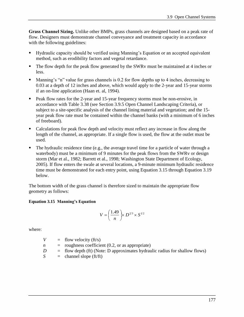
3.9 Open Channel Systems
177
Grass Channel Sizing. Unlike other BMPs, grass channels are designed based on a peak rate of
flow. Designers must demonstrate channel conveyance and treatment capacity in accordance
with the following guidelines:
Hydraulic capacity should be verified using Manning’s Equation or an accepted equivalent
method, such as erodibility factors and vegetal retardance.
The flow depth for the peak flow generated by the SWRv must be maintained at 4 inches or
less.
Manning’s ―n‖ value for grass channels is 0.2 for flow depths up to 4 inches, decreasing to
0.03 at a depth of 12 inches and above, which would apply to the 2-year and 15-year storms
if an on-line application (Haan et. al, 1994).
Peak flow rates for the 2-year and 15-year frequency storms must be non-erosive, in
accordance with Table 3.38 (see Section 3.9.5 Open Channel Landscaping Criteria), or
subject to a site-specific analysis of the channel lining material and vegetation; and the 15-
year peak flow rate must be contained within the channel banks (with a minimum of 6 inches
of freeboard).
Calculations for peak flow depth and velocity must reflect any increase in flow along the
length of the channel, as appropriate. If a single flow is used, the flow at the outlet must be
used.
The hydraulic residence time (e.g., the average travel time for a particle of water through a
waterbody) must be a minimum of 9 minutes for the peak flows from the SWRv or design
storm (Mar et al., 1982; Barrett et al., 1998; Washington State Department of Ecology,
2005). If flow enters the swale at several locations, a 9-minute minimum hydraulic residence
time must be demonstrated for each entry point, using Equation 3.15 through Equation 3.19
below.
The bottom width of the grass channel is therefore sized to maintain the appropriate flow
geometry as follows:
Equation 3.15 Manning’s Equation
213249.1SD
nV
where:
V = flow velocity (ft/s)
n = roughness coefficient (0.2, or as appropriate)
D = flow depth (ft) (Note: D approximates hydraulic radius for shallow flows)
S = channel slope (ft/ft)

Chapter 3 Stormwater Best Management Practices (BMPs)
178
Equation 3.16 Continuity Equation
DWVQ
where:
Q = design storm peak flow rate (cfs)
V = design storm flow velocity (ft/s)
W = channel width (ft)
D = flow depth (ft)
(Note: Channel width (W) multiplied by depth (D) approximates the cross-sectional flow
area for shallow flows.)
Combining Equation 3.15 and Equation 3.16, and re-writing them provides a solution for the
minimum width:
Equation 3.17 Minimum Width
213549.1 SD
QnW
Solving Equation 3.20 for the corresponding velocity provides:
Equation 3.18 Corresponding Velocity
DW
QV
The width, slope, or Manning’s ―n‖ value can be adjusted to provide an appropriate channel
design for the site conditions. However, if a higher density of grass is used to increase the
Manning’s ―n‖ value and decrease the resulting channel width, it is important to provide material
specifications and construction oversight to ensure that the denser vegetation is actually
established. Equation 3.19 can then be used to ensure adequate hydraulic residence time.
Equation 3.19 Grass Channel Length for Hydraulic Residence Time of 9 minutes (540 seconds)
VL 540
where:
L = minimum swale length (ft)
V = flow velocity (ft/s)
The storage volume (Sv) provided by the grass channel is equal to the total runoff from the
design storm (typically SWRv) used to size the channel (conveyed at a depth of 4 inches or less).

3.9 Open Channel Systems
179
Equation 3.20 Grass Channel Storage Volume
mDesignStorSv
where:
DesignStorm = SWRv or other design storm volume (ft3) (e.g., portion of the
SWRv)
Dry Swale Sizing. Dry swales are typically sized to capture the SWRv or larger design storm
volumes in the surface ponding area, soil media, and gravel reservoir layers of the dry swale.
Total storage volume of the BMP is calculated using Equation 3.21.
Equation 3.21 Dry Swale Storage Volume
)(][ pondingaveragegravelgravelmediamediabottom dSAddSASv
where:
Sv = total storage volume of dry swale (ft3)
SAbottom = bottom surface area of dry swale (ft2)
dmedia = depth of the filter media (ft)
ηmedia = effective porosity of the filter media (typically 0.25)
dgravel = depth of the underdrain and underground storage gravel layer(ft)
ηgravel = effective porosity of the gravel layer (typically 0.4)
SAaverage = the average surface area of the dry swale (ft2)
typically, where SAtop is the top surface area of bioretention,
2
topbottom
average
SASASA
dponding = the maximum ponding depth of the dry swale (ft)
Equation 3.21 can be modified if the storage depths of the soil media, gravel layer, or ponded
water vary in the actual design or with the addition of any surface or subsurface storage
components (e.g., additional area of surface ponding, subsurface storage chambers, etc.). The
maximum depth of ponding in the dry swale must not exceed 18 inches. If storage practices will
be provided off-line or in series with the dry swale, the storage practices should be sized using
the guidance in Section 3.12 Storage Practices.
Dry swales can be designed to address, in whole or in part, the detention storage needed to
comply with channel protection and/or flood control requirements. The Sv can be counted as part
of the 2-year or 15-year runoff volumes to satisfy stormwater quantity control requirements.
Note: In order to increase the storage volume of a dry swale, the ponding surface area may be
increased beyond the filter media surface area. However, the top surface are of the BMP (at the
top of the ponding elevation) may not be more than twice the size of surface area of the filter
media (SAbottom).

Chapter 3 Stormwater Best Management Practices (BMPs)
180
Wet Swale Sizing. Wet swales can be designed to capture and treat the SWRv remaining from
any upstream stormwater retention practices. The storage volume is made up of the temporary
and permanent storage created within each wet swale cell. This includes the permanent pool
volume and up to 12 inches of temporary storage created by check dams or other design features
that has 24 hours extended detention.
The storage volume (Sv) of the practice is equal to the volume provided by the pond permanent
pool plus the 24-hour extended detention (ED) volume provided by the practice (Equation 3.22).
The total Sv cannot exceed the design SWRv.
Equation 3.22 Wet Swale Storage Volume
Sv = Pond permanent pool volume + 24-hour ED volume
3.9.5 Open Channel Landscaping Criteria
All open channels must be stabilized to prevent erosion or transport of sediment to receiving
practices or drainage systems. There are several types of grasses appropriate for dry open
channels (grass channels and dry swales). These are listed in Table 3.38. Designers should
choose plant species that can withstand both wet and dry periods and relatively high velocity
flows for planting within the channel. Designers should ensure that the maximum flow velocities
do not exceed the values listed in the table for the selected grass species and the specific site
slope.
Table 3.38 Recommended Vegetation for Open Channels
Wet swales should be planted with grass and wetland plant species that can withstand both wet
and dry periods as well as relatively high velocity flows within the channel. For a list of wetland
plant species suitable for use in wet swales, refer to the wetland panting guidance and plant lists
provided in Section 3.11 Stormwater Wetlands.
If roadway salt will be applied to the contributing drainage area, open channels should be planted
with salt-tolerant plant species.
Vegetation Type Slope (%) Maximum Velocity (ft/s)
Erosion Resistant Soil Easily Eroded Soil
Bermuda Grass 0-5 8 6
5-10 7 5
>10 6 4
Kentucky Bluegrass 0-5 7 5
5-10 6 4
>10 5 3
Tall Fescue Grass Mixture 0-5 6 4
5-10 4 3
Annual and Perennial Rye 0-5 4 3
Sod 4 3
Source: USDA, TP-61, 1954; Roanoke Virginia, Stormwater Design Manual, 2008
3.9 Open Channel Systems
181
Landscape design shall specify proper grass species based on site-specific soils and hydric
conditions present along the channel.
Open channels should be seeded at such a density to achieve a 90 percent vegetated cover after
the second growing season. Taller and denser grasses are preferable, although the species is less
important than good stabilization and dense vegetative cover.
Grass channels should be seeded and not sodded. Seeding establishes deeper roots and sod may
have muck soil that is not conducive to infiltration. Grass channels should be protected by a
biodegradable erosion control fabric to provide immediate stabilization of the channel bed and
banks.
3.9.6 Open Channel Construction Sequence
Design Notes. Channel invert and tops of banks are to be shown in plan and profile views. A
cross sectional view of each configuration must be shown for proposed channels. Completed
limits of grading must be shown for proposed channels. For proposed channels, the transition at
the entrance and outfall is to be clearly shown on plan and profile views.
Open Channel Installation. The following is a typical construction sequence to properly install
open channels, although steps may be modified to reflect different site conditions or design
variations. Grass channels should be installed at a time of year that is best to establish turf cover
without irrigation. For more specific information on the installation of wet swales, designers
should consult the construction criteria outlined in Section 3.11 Stormwater Wetlands.
Step 1: Protection During Site Construction. Ideally, open channels should remain outside
the limit of disturbance during construction to prevent soil compaction by heavy equipment.
However, this is seldom practical, given that the channels are a key part of the drainage system at
most sites. In these cases, temporary soil erosion and sediment controls such as dikes, silt fences
and other erosion control measures should be integrated into the swale design throughout the
construction sequence. Specifically, barriers should be installed at key check dam locations, and
erosion control fabric should be used to protect the channel. Dry Swales that lack underdrains
(and rely on infiltration) must be fully protected by silt fence or construction fencing to prevent
compaction by heavy equipment during construction.
Step 2: Installation. Installation may only begin after the entire contributing drainage area
has been stabilized with vegetation. Any accumulation of sediments that does occur within the
channel must be removed during the final stages of grading to achieve the design cross section.
Soil erosion and sediment controls for construction of the channel must be installed as specified
in the soil erosion and sediment control plan. Stormwater flows must not be permitted into the
channel until the bottom and side slopes are fully stabilized.
Step 3: Grading. Grade the grass channel to the final dimensions shown on the plan.
Excavators or backhoes should work from the sides to grade and excavate the open channels to
the appropriate design dimensions. Excavating equipment should have scoops with adequate
reach so they do not have to sit inside the footprint of the open channel area. If constructing a dry
swale, the bottom of the swale should be ripped, rototilled or otherwise scarified to promote
greater infiltration.
Chapter 3 Stormwater Best Management Practices (BMPs)
182
Step 4: Placing Stone Layer (for dry swales). If constructing a dry swale, place an
acceptable geotextile fabric on the underground (excavated) sides of the dry swale with a
minimum 6 inch overlap. Place the stone needed for storage layer over the filter bed. Perforate
the underdrain pipe. Add the remaining stone jacket, and then pack #57 stone (clean double
washed) to 3 inches above the top of the underdrain, and then add 3 inches of pea gravel as a
filter layer. Add the soil media in 12-inch lifts until the desired top elevation of the dry swale is
achieved. Water thoroughly and add additional media as needed where settlement has occurred.
Step 5: Add Amendments (optional, for grass channels). Add soil amendments as needed.
Till the bottom of the grass channel to a depth of 1 foot and incorporate compost amendments
according to Appendix J.
Step 6: Install Check Dams. Install check dams, driveway culverts and internal pretreatment
features as shown on the plan. Fill material used to construct check dams should be placed in 8-
to 12-inch lifts and compacted to prevent settlement. The top of each check dam must be
constructed level at the design elevation.
Step 7: Hydro-seed. Hydro-seed the bottom and banks of the open channel, and peg in
erosion control fabric or blanket where needed. After initial planting, a biodegradable erosion
control fabric should be used, conforming to the District of Columbia Soil Erosion and Sediment
Control Standards and Specifications.
Step 8: Plant. Plant landscaping materials as shown in the landscaping plan, and water them
weekly during the first 2 months. The construction contract should include a care and
replacement warranty to ensure that vegetation is properly established and survives during the
first growing season following construction.
Step 9: Final Inspection. A qualified professional should conduct the final construction
inspection and develop a punch list for facility acceptance.
Open Channel Construction Supervision. Supervision during construction is recommended to
ensure that the open channel is built in accordance with these specifications.
DDOE’s construction phase inspection checklist is available in Appendix K.
Some common pitfalls can be avoided by careful construction supervision that focuses on the
following key aspects of dry swale installation:
Make sure the desired coverage of turf or erosion control fabric has been achieved following
construction, both on the channel beds and their contributing side-slopes.
Inspect check dams and pretreatment structures to make sure they are at correct elevations,
are properly installed, and are working effectively.
For dry swale designs:
Check the filter media to confirm that it meets specifications and is installed to the
correct depth.
Check elevations, such as the invert of the underdrain, inverts for the inflow and outflow
points, and the ponding depth provided between the surface of the filter bed and the
overflow structure.

3.9 Open Channel Systems
183
Ensure that caps are placed on the upstream (but not the downstream) ends of the
underdrains.
Check that outfall protection/energy dissipation measures at concentrated inflow and
outflow points are stable.
The real test of an open channel occurs after its first big storm. The post-storm inspection should
focus on whether the desired sheetflow, shallow concentrated flows or fully concentrated flows
assumed in the plan actually occur in the field. Minor adjustments are normally needed as part of
this post-storm inspection (e.g., spot reseeding, gully repair, added armoring at inlets, or
realignment of outfalls and check dams). Also, a qualified professional should check that dry
swale practices drain completely within the 72-hour drawdown period.
3.9.7 Open Channel Maintenance Criteria
Maintenance is a crucial and required element that ensures the long-term performance of open
channels. Once established, grass channels have minimal maintenance needs outside of the
spring cleanup, regular mowing, repair of check dams and other measures to maintain the
hydraulic efficiency of the channel and a dense, healthy grass cover. Dry swale designs may
require regular pruning and management of trees and shrubs. The surface of dry swale filter beds
can become clogged with fine sediment over time, but this can be alleviated through core
aeration or deep tilling of the filter bed. Additional effort may be needed to repair check dams,
stabilize inlet points, and remove deposited sediment from pretreatment cells. Table 3.39
provides a schedule of typical maintenance activities required for open channels.
Table 3.39 Typical Maintenance Activities and Schedule for Open Channels
Schedule Maintenance Activity
As needed Mow grass channels and dry swales during the growing season to maintain grass heights
in the 4- to 6-inch range.
Quarterly
Ensure that the contributing drainage area, inlets, and facility surface are clear of debris.
Ensure that the contributing drainage area is stabilized. Perform spot-reseeding if where
needed.
Remove accumulated sediment and oil/grease from inlets, pretreatment devices, flow
diversion structures, and overflow structures.
Repair undercut and eroded areas at inflow and outflow structures.
Annual inspection
Add reinforcement planting to maintain 90% turf cover. Reseed any salt-killed vegetation.
Remove any accumulated sand or sediment deposits behind check dams.
Inspect upstream and downstream of check dams for evidence of undercutting or erosion,
and remove and trash or blockages at weep holes.
Examine channel bottom for evidence of erosion, braiding, excessive ponding or dead
grass.
Check inflow points for clogging and remove any sediment.
Inspect side slopes and grass filter strips for evidence of any rill or gully erosion and
repair.
Look for any bare soil or sediment sources in the contributing drainage area and stabilize
immediately.

Chapter 3 Stormwater Best Management Practices (BMPs)
184
Maintenance Inspections. Annual inspections by a qualified professional are used to trigger
maintenance operations, such as sediment removal, spot revegetation, and inlet stabilization.
DDOE’s maintenance inspection checklists for disconnection and the Maintenance Service
Completion Inspection form can be found in Appendix L.
Declaration of Covenants. A declaration of covenants that includes all maintenance
responsibilities to ensure the continued stormwater performance for the BMP is required. The
declaration of covenants specifies the property owner’s primary maintenance responsibilities,
and authorizes DDOE staff to access the property for inspection or corrective action in the event
the proper maintenance is not performed. The declaration of covenants is attached to the deed of
the property. A template form is provided at the end of Chapter 5 (see Figure 5.4), although
variations will exist for scenarios where stormwater crosses property lines. The covenant is
between the property and the Government of the District of Columbia. It is submitted through the
Office of the Attorney General. All SWMPs have a maintenance agreement stamp that must be
signed for a building permit to proceed. A maintenance schedule must appear on the SWMP.
Additionally, a maintenance schedule is required in Exhibit C of the declaration of covenants.
Covenants are not required on government properties, but maintenance responsibilities must be
defined through a partnership agreement or a memorandum of understanding.
Waste Material. Waste material from the repair, maintenance, or removal of a BMP or land
cover shall be removed and disposed of in compliance with applicable federal and District law.
3.9.8 Open Channel Stormwater Compliance Calculations
Grass Channels receive 10 percent retention value and are not an accepted total suspended solids
practice for the amount of storage volume (Sv) provided by the BMP (Table 3.40).
Table 3.40 Grass Channel Retention Value and Pollutant Removal
Retention Value = 0.1× Sv
Accepted Total Suspended Solids (TSS)
Treatment Practice No
Grass channels on amended soils receive 30 percent retention value l for the amount of storage
volume (Sv) provided by the practice (Table 3.41).
Table 3.41 Grass Channel on Amended Soils Retention Value and Pollutant Removal
Retention Value = 0.3 × Sv
Accepted TSS Treatment Practice No
Dry swales receive 60 percent retention value and are an accepted TSS removal practice for the
amount of storage volume (Sv) provided by the practice (Table 3.42).
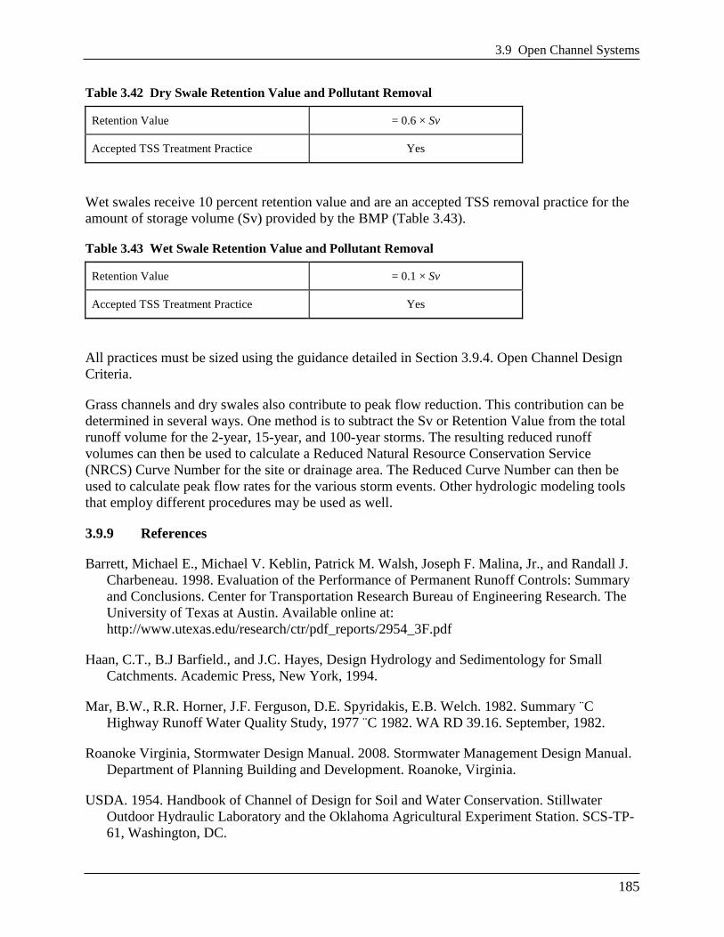
3.9 Open Channel Systems
185
Table 3.42 Dry Swale Retention Value and Pollutant Removal
Retention Value = 0.6 × Sv
Accepted TSS Treatment Practice Yes
Wet swales receive 10 percent retention value and are an accepted TSS removal practice for the
amount of storage volume (Sv) provided by the BMP (Table 3.43).
Table 3.43 Wet Swale Retention Value and Pollutant Removal
Retention Value = 0.1 × Sv
Accepted TSS Treatment Practice Yes
All practices must be sized using the guidance detailed in Section 3.9.4. Open Channel Design
Criteria.
Grass channels and dry swales also contribute to peak flow reduction. This contribution can be
determined in several ways. One method is to subtract the Sv or Retention Value from the total
runoff volume for the 2-year, 15-year, and 100-year storms. The resulting reduced runoff
volumes can then be used to calculate a Reduced Natural Resource Conservation Service
(NRCS) Curve Number for the site or drainage area. The Reduced Curve Number can then be
used to calculate peak flow rates for the various storm events. Other hydrologic modeling tools
that employ different procedures may be used as well.
3.9.9 References
Barrett, Michael E., Michael V. Keblin, Patrick M. Walsh, Joseph F. Malina, Jr., and Randall J.
Charbeneau. 1998. Evaluation of the Performance of Permanent Runoff Controls: Summary
and Conclusions. Center for Transportation Research Bureau of Engineering Research. The
University of Texas at Austin. Available online at:
http://www.utexas.edu/research/ctr/pdf_reports/2954_3F.pdf
Haan, C.T., B.J Barfield., and J.C. Hayes, Design Hydrology and Sedimentology for Small
Catchments. Academic Press, New York, 1994.
Mar, B.W., R.R. Horner, J.F. Ferguson, D.E. Spyridakis, E.B. Welch. 1982. Summary ¨C
Highway Runoff Water Quality Study, 1977 ¨C 1982. WA RD 39.16. September, 1982.
Roanoke Virginia, Stormwater Design Manual. 2008. Stormwater Management Design Manual.
Department of Planning Building and Development. Roanoke, Virginia.
USDA. 1954. Handbook of Channel of Design for Soil and Water Conservation. Stillwater
Outdoor Hydraulic Laboratory and the Oklahoma Agricultural Experiment Station. SCS-TP-
61, Washington, DC.

Chapter 3 Stormwater Best Management Practices (BMPs)
186
Virginia DCR Stormwater Design Specification No. 3: Grass Channels Version 1.8. 2010.
Virginia DCR Stormwater Design Specification No. 10: Dry Swales Version 1.8. 2010.
Virginia DCR Stormwater Design Specification No. 11: Wet Swales Version 1.8. 2010.
Washington State Department of Ecology. 2005. Stormwater Manual for Western Washington.
State of Washington Department of Ecology. Available online at:
http://www.ecy.wa.gov/programs/wq/stormwater/manual.html

3.10 Ponds
187
3.10 Ponds
Definition. Stormwater ponds are stormwater storage practices that consist of a combination of a
permanent pool, micropool, or shallow marsh that promote a good environment for gravitational
settling, biological uptake and microbial activity. Ponds are widely applicable for most land uses
and are best suited for larger drainage areas. Runoff from each new storm enters the pond and
partially displaces pool water from previous storms. The pool also acts as a barrier to re-
suspension of sediments and other pollutants deposited during prior storms. When sized
properly, stormwater ponds have a residence time that ranges from many days to several weeks,
which allows numerous pollutant removal mechanisms to operate. Stormwater ponds can also
provide storage above the permanent pool to help meet stormwater management requirements for
larger storms. Design variants include:
P-1 Micropool extended detention pond
P-2 Wet pond
P-3 Wet extended detention pond
Stormwater ponds should be considered for use after all other upland retention opportunities
have been exhausted and there is still a remaining treatment volume or runoff from larger storms
(i.e., 2-year, 15-year or flood control events) to manage.
Stormwater ponds do not receive any stormwater retention value and should be considered only
for management of larger storm events. Stormwater ponds have both community and
environmental concerns (see Section 3.10.1 Pond Feasibility Criteria) that should be considered
before choosing stormwater ponds for the appropriate stormwater practice on site.

Chapter 3 Stormwater Best Management Practices (BMPs)
188
Figure 3.35 Design schematics for a wet pond (P-2).

3.10 Ponds
189
Figure 3.36 Typical extended detention pond (P-3) details.
3.10.1 Pond Feasibility Criteria

Chapter 3 Stormwater Best Management Practices (BMPs)
190
The following feasibility issues need to be considered when ponds are considered a final
stormwater management practice of the treatment train.
Adequate Water Balance. Wet ponds must have enough water supplied from groundwater,
runoff or baseflow so that the wet pools will not draw down by more than 2 feet after a 30-day
summer drought. A simple water balance calculation must be performed using the equation
provided in Section 3.10.4. Wetland Design Criteria and Section 3.11.4 Wetland Design Criteria.
Contributing Drainage Area. A contributing drainage area of 10 to 25 acres is typically
recommended for ponds to maintain constant water elevations. Ponds can still function with
drainage areas less than 10 acres, but designers should be aware that these ―pocket‖ ponds will
be prone to clogging, experience fluctuating water levels, and generate more nuisance
conditions.
Space Requirements. The surface area of a pond will normally be at least 1 to 3 percent of its
contributing drainage area, depending on the pond’s depth.
Site Topography. Ponds are best applied when the grade of contributing slopes is less than 15
percent.
Available Hydraulic Head. The depth of a pond is usually determined by the hydraulic head
available on the site. The bottom elevation is normally the invert of the existing downstream
conveyance system to which the pond discharges. Typically, a minimum of 6 to 8 feet of head
are needed to hold the wet pool and any additional large storm storage or overflow capacity for a
pond to function.
Setbacks. To avoid the risk of seepage, stormwater ponds must not be hydraulically connected to
structure foundations. Setbacks to structures must be at least 10 feet and adequate water-proofing
protection must be provided for foundations and basements.
Proximity to Utilities. For an open pond system, no utility lines shall be permitted to cross any
part of the embankment of a wet pool.
Depth to Water Table. The depth to the groundwater table is not a major constraint for
wetponds because a high water table can help maintain wetland conditions. However,
groundwater inputs can also reduce the pollutant removal rates of ponds. Further, if the water
table is close to the surface, it may make excavation difficult and expensive.
Soils. Highly permeable soils will make it difficult to maintain a healthy permanent pool. Soil
infiltration tests need to be conducted at proposed pond sites to determine the need for a pond
liner or other method to ensure a constant water surface elevation. Underlying soils of
Hydrologic Soil Group (HSG) C or D should be adequate to maintain a permanent pool. Most
HSG A soils and some HSG B soils will require a liner (see Table 3.44). Geotechnical tests
should be conducted to determine the infiltration rates and other subsurface properties of the
soils beneath the proposed pond.

3.10 Ponds
191
Use of or Discharges to Natural Wetlands. Ponds cannot be located within jurisdictional
waters, including wetlands, without obtaining a section 404 permit from the appropriate state or
federal regulatory agency. In addition, the designer should investigate the wetland status of
adjacent areas to determine if the discharge from the pond will change the hydroperiod of a
downstream natural wetland (see Cappiella et al., 2006, for guidance on minimizing stormwater
discharges to existing wetlands).
Perennial Streams. Locating ponds on perennial streams will require both a Section 401 and
Section 404 permit from the appropriate state or federal regulatory agency.
Community and Environmental Concerns. Ponds can generate the following community and
environmental concerns that need to be addressed during design:
Aesthetic Issues. Many residents feel that ponds are an attractive landscape feature, promote
a greater sense of community and are an attractive habitat for fish and wildlife. Designers
should note that these benefits are often diminished where ponds are under-sized or have
small contributing drainage areas.
Existing Forests. Construction of a pond may involve extensive clearing of existing forest
cover. Designers can expect a great deal of neighborhood opposition if they do not make a
concerted effort to save mature trees during pond design and construction. In the District of
Columbia a permit is required to remove a tree with a circumference greater than 55-inches
on private lands. A permit is required to prune or remove any street tree between the
sidewalk and the curb. These permits are issued by the District Department of
Transportation, Urban Forestry Administration (UFA).
Safety Risk. Pond safety is an important community concern, since both young children and
adults have perished by drowning in ponds through a variety of accidents, including falling
through thin ice cover. Gentle side slopes and safety benches should be provided to avoid
potentially dangerous drop-offs, especially where ponds are located near residential areas.
Pollutant Concerns. Ponds collect and store water and sediment to increase residence time
that will increase the likelihood for contaminated water and sediments to be neutralized.
However, poorly sized, maintained, and/or functioning ponds can export contaminated
sediments and/or water to receiving waterbodies (Mallin, 2000; Mallin et al., 2001;
Messersmith, 2007). Further, designers are cautioned that recent research on ponds has
shown that some ponds can be hotspots or incubators for algae that generate harmful algal
blooms (HABs).
Mosquito Risk. Mosquitoes are not a major problem for larger ponds (Santana et al., 1994;
Ladd and Frankenburg, 2003, Hunt et al, 2005). However, fluctuating water levels in smaller
or under-sized ponds could pose some risk for mosquito breeding. Mosquito problems can be
minimized through simple design features and maintenance operations described in MSSC
(2005).
Geese and Waterfowl. Ponds with extensive turf and shallow shorelines can attract nuisance
populations of resident geese and other waterfowl, whose droppings add to the nutrient and
bacteria loads, thus reducing the removal efficiency for those pollutants. Several design and
landscaping features can make ponds much less attractive to geese (see Schueler, 1992).

Chapter 3 Stormwater Best Management Practices (BMPs)
192
3.10.2 Pond Conveyance Criteria
Internal Slope. The longitudinal slope of the pond bottom should be at least 0.5 to 1 percent to
facilitate maintenance.
Primary Spillway. The spillway shall be designed with acceptable anti-flotation, anti-vortex and
trash rack devices. The spillway must generally be accessible from dry land. When reinforced
concrete pipe is used for the principal spillway to increase its longevity, ―O-ring‖ gaskets
(ASTM C361) shall be used to create watertight joints.
Non-Clogging Low-Flow Orifice. A low-flow orifice must be provided that is adequately
protected from clogging by either an acceptable external trash rack or by internal orifice
protection that may allow for smaller diameters. Orifices less than 3 inches in diameter may
require extra attention during design, to minimize the potential for clogging.
One option is a submerged reverse-slope pipe that extends downward from the riser to an
inflow point 1 foot below the normal pool elevation.
Alternative methods must employ a broad crested rectangular V-notch (or proportional) weir,
protected by a half-round CMP that extends at least 12 inches below the normal pool
elevation.
Emergency Spillway. Ponds must be constructed with overflow capacity to pass the 100-year
design storm event through either the primary spillway or a vegetated or armored emergency
spillway unless waived by DDOE.
Adequate Outfall Protection. The design must specify an outfall that will be stable for the 15-
year design storm event. The channel immediately below the pond outfall must be modified to
prevent erosion and conform to natural dimensions in the shortest possible distance. This is
typically done by placing appropriately sized riprap over geotextile fabric, which can reduce
flow velocities from the principal spillway to non-erosive levels (3.5 to 5.0 fps) depending on the
channel lining material. Flared pipe sections, which discharge at or near the stream invert or into
a step pool arrangement, should be used at the spillway outlet.
When the discharge is to a manmade pipe or channel system, the system must be adequate to
convey the required design storm peak discharge.
If a pond daylights to a channel with dry weather flow, care should be taken to minimize tree
clearing along the downstream channel, and to reestablish a forested riparian zone in the shortest
possible distance. Excessive use of rip-rap should be avoided.
The final release rate of the facility shall be modified if any increase in flooding or stream
channel erosion would result at a downstream structure, highway, or natural point of restricted
streamflow (see Section 2.6 Additional Stormwater Management Requirements).
Inlet Protection. Inflow points into the pond must be stabilized to ensure that non-erosive
conditions exist during storm events up to the overbank flood event (i.e., the 15-year storm
event). Inlet pipe inverts should generally be located at or slightly below the permanent pool

3.10 Ponds
193
elevation. A forebay shall be provided at each inflow location, unless the inlet is submerged or
inflow provides less than 10 percent of the total design storm inflow to the pond.
Dam Safety Permits. The designer must verify whether or not Dam Safety permits or approvals
are required for the embankment.
3.10.3 Pond Pretreatment Criteria
Sediment forebays are considered to be an integral design feature to maintain the longevity of all
ponds. A forebay must be located at each major inlet to trap sediment and preserve the capacity
of the main treatment cell. The following criteria apply to forebay design:
A major inlet is defined as an individual storm drain inlet pipe or open channel serving at
least 10 percent of the pond’s contributing drainage area.
The forebay consists of a separate cell, formed by an acceptable barrier (e.g., an earthen
berm, concrete weir, gabion baskets, etc.).
The forebay should be between 4 and 6 feet deep and must be equipped with a variable width
aquatic bench for safety purposes. The aquatic bench should be 4 to 6 feet wide at a depth of
1 to 2 feet below the water surface. Small forebays may require alternate geometry to achieve
the goals of pretreatment and safety within a small area.
The forebay shall be sized to contain 0.1 inches of runoff from the contributing drainage
impervious area. The relative size of individual forebays should be proportional to the
percentage of the total inflow to the pond.
The bottom of the forebay may be hardened (e.g., with concrete, asphalt, or grouted riprap) to
make sediment removal easier.
The forebay must be equipped with a metered rod in the center of the pool (as measured
lengthwise along the low-flow water travel path) for long-term monitoring of sediment
accumulation.
Exit velocities from the forebay shall be non-erosive or an armored overflow shall be
provided. Non-erosive velocities are 4 feet per second for the two-year event, and 6 feet per
second for the 15-year event.
Direct maintenance access for appropriate equipment shall be provided to the each forebay.
The bottom of the forebay may be hardened to make sediment removal easier.
3.10.4 Pond Design Criteria
Pond Storage Design. The pond permanent pool must be sized to store a volume equivalent to
the SWRv. Volume storage may be provided in multiple cells. Performance is enhanced when
multiple treatment pathways are provided by using multiple cells, longer flowpaths, high surface
area to volume ratios, complex microtopography, and/or redundant treatment methods
(combinations of pool, ED, and marsh).
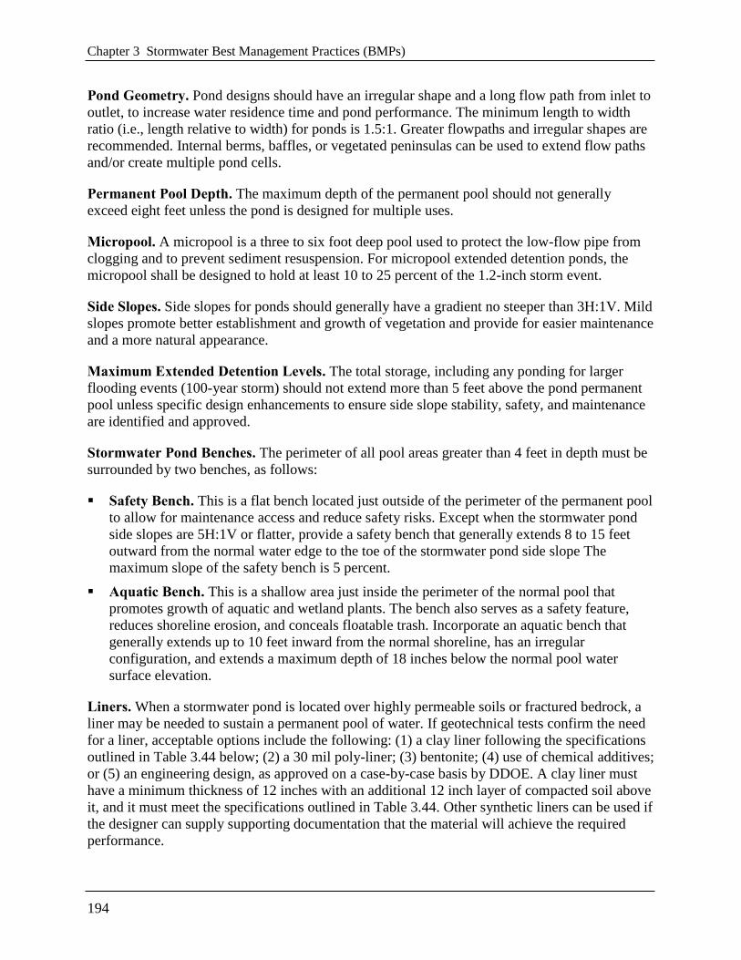
Chapter 3 Stormwater Best Management Practices (BMPs)
194
Pond Geometry. Pond designs should have an irregular shape and a long flow path from inlet to
outlet, to increase water residence time and pond performance. The minimum length to width
ratio (i.e., length relative to width) for ponds is 1.5:1. Greater flowpaths and irregular shapes are
recommended. Internal berms, baffles, or vegetated peninsulas can be used to extend flow paths
and/or create multiple pond cells.
Permanent Pool Depth. The maximum depth of the permanent pool should not generally
exceed eight feet unless the pond is designed for multiple uses.
Micropool. A micropool is a three to six foot deep pool used to protect the low-flow pipe from
clogging and to prevent sediment resuspension. For micropool extended detention ponds, the
micropool shall be designed to hold at least 10 to 25 percent of the 1.2-inch storm event.
Side Slopes. Side slopes for ponds should generally have a gradient no steeper than 3H:1V. Mild
slopes promote better establishment and growth of vegetation and provide for easier maintenance
and a more natural appearance.
Maximum Extended Detention Levels. The total storage, including any ponding for larger
flooding events (100-year storm) should not extend more than 5 feet above the pond permanent
pool unless specific design enhancements to ensure side slope stability, safety, and maintenance
are identified and approved.
Stormwater Pond Benches. The perimeter of all pool areas greater than 4 feet in depth must be
surrounded by two benches, as follows:
Safety Bench. This is a flat bench located just outside of the perimeter of the permanent pool
to allow for maintenance access and reduce safety risks. Except when the stormwater pond
side slopes are 5H:1V or flatter, provide a safety bench that generally extends 8 to 15 feet
outward from the normal water edge to the toe of the stormwater pond side slope The
maximum slope of the safety bench is 5 percent.
Aquatic Bench. This is a shallow area just inside the perimeter of the normal pool that
promotes growth of aquatic and wetland plants. The bench also serves as a safety feature,
reduces shoreline erosion, and conceals floatable trash. Incorporate an aquatic bench that
generally extends up to 10 feet inward from the normal shoreline, has an irregular
configuration, and extends a maximum depth of 18 inches below the normal pool water
surface elevation.
Liners. When a stormwater pond is located over highly permeable soils or fractured bedrock, a
liner may be needed to sustain a permanent pool of water. If geotechnical tests confirm the need
for a liner, acceptable options include the following: (1) a clay liner following the specifications
outlined in Table 3.44 below; (2) a 30 mil poly-liner; (3) bentonite; (4) use of chemical additives;
or (5) an engineering design, as approved on a case-by-case basis by DDOE. A clay liner must
have a minimum thickness of 12 inches with an additional 12 inch layer of compacted soil above
it, and it must meet the specifications outlined in Table 3.44. Other synthetic liners can be used if
the designer can supply supporting documentation that the material will achieve the required
performance.

3.10 Ponds
195
Table 3.44 Clay Liner Specifications
Property Test Method Unit Specification
Permeability ASTM D-2434 cm/s 1 × 10⁻⁶
Plasticity Index of Clay ASTM D-423/424 % Not less than 15
Liquid Limit of Clay ASTM D-2216 % Not less than 30
Clay Particles Passing ASTM D-422 % Not less than 30
Clay Compaction ASTM D-2216 % 95% of standard proctor density
Source: DCR (1999). VA
Required Geotechnical Testing. Soil borings must be taken below the proposed embankment,
in the vicinity of the proposed outlet area, and in at least two locations within the proposed pond
treatment area. Soil boring data is needed to (1) determine the physical characteristics of the
excavated material, (2) determine its adequacy for use as structural fill or spoil, (3) provide data
for structural designs of the outlet works (e.g., bearing capacity and buoyancy), (4) determine
compaction/composition needs for the embankment (5) determine the depth to groundwater and
bedrock and (6) evaluate potential infiltration losses (and the potential need for a liner).
Non-clogging Low-Flow (Extended Detention) Orifice. The low-flow ED orifice shall be
adequately protected from clogging by an acceptable external trash rack. The preferred method is
a submerged reverse-slope pipe that extends downward from the riser to an inflow point one foot
below the normal pool elevation. Alternative methods are to employ a broad crested rectangular,
V-notch, or proportional weir, protected by a half-round CMP that extends at least 12 inches
below the normal pool.
Riser in Embankment. The riser should be located within the embankment for maintenance
access, safety, and aesthetics. Access to the riser is to be provided by lockable manhole covers,
and manhole steps within easy reach of valves and other controls. The principal spillway opening
can be "fenced" with pipe or rebar at 8-inch intervals for safety purposes.
Trash Racks. Trash racks shall be provided for low-flow pipes and for riser openings not having
anti-vortex devices.
Pond Drain. Ponds should have a drainpipe that can completely or partially drain the permanent
pool. In cases where a low level drain is not feasible (such as in an excavated pond), a pump well
must be provided to accommodate a temporary pump intake when needed to drain the pond.
The drainpipe must have an upturned elbow or protected intake within the pond to help keep
it clear of sediment deposition, and a diameter capable of draining the pond within 24 hours.
The pond drain must be equipped with an adjustable valve located within the riser, where it
will not be normally inundated and can be operated in a safe manner.
Care must be exercised during pond drawdowns to prevent downstream discharge of sediments
or anoxic water and rapid drawdown. The approving authority shall be notified before draining a
pond.

Chapter 3 Stormwater Best Management Practices (BMPs)
196
Adjustable Gate Valve. Both the outlet pipe and the pond drain must be equipped with an
adjustable gate valve (typically a handwheel activated knife gate valve) or pump well and be
sized one pipe size greater than the calculated design diameter. Valves must be located inside of
the riser at a point where they (a) will not normally be inundated and (b) can be operated in a
safe manner. To prevent vandalism, the handwheel should be chained to a ringbolt, manhole
step, or other fixed object.
Safety Features.
The principal spillway opening must be designed and constructed to prevent access by small
children.
End walls above pipe outfalls greater than 48 inches in diameter must be fenced to prevent a
hazard.
Storage practices must incorporate an additional 1 foot of freeboard above the emergency
spillway, or 2 feet of freeboard if design has no emergency spillway, for the maximum Qf
design storm unless more stringent Dam Safety requirements apply.
The emergency spillway must be located so that downstream structures will not be impacted
by spillway discharges.
Both the safety bench and the aquatic bench should be landscaped with vegetation that
hinders or prevents access to the pool.
Warning signs prohibiting swimming must be posted.
Where permitted, fencing of the perimeter of ponds is discouraged. The preferred method to
reduce risk is to manage the contours of the stormwater pond to eliminate drop-offs or other
safety hazards. Fencing is required at or above the maximum water surface elevation in the
rare situations when the pond slope is a vertical wall.
Side slopes to the pond shall not be steeper than 3H:1V, and shall terminate on a 15 ft wide
safety bench. Both the safety bench and the aquatic bench may be landscaped to prevent
access to the pool. The bench requirement may be waived if slopes are 4H:1V or flatter.
Maintenance Reduction Features. Many maintenance issues can be addressed through well
design access. All ponds must be designed for annual maintenance. Good access is needed so
crews can remove sediments, make repairs, and preserve pond-treatment capacity. Design for the
following,
Adequate maintenance access must extend to the forebay, safety bench, riser, and outlet
structure and must have sufficient area to allow vehicles to turn around.
The riser should be located within the embankment for maintenance access, safety and
aesthetics. Access to the riser should be provided by lockable manhole covers and
manhole steps within easy reach of valves and other controls.
Access roads must (1) be constructed of load-bearing materials or be built to withstand
the expected frequency of use, (2) have a minimum width of 15 feet, and (3) have a
profile grade that does not exceed 5:1.

3.10 Ponds
197
A maintenance right-of-way or easement must extend to the stormwater pond from a
public or private road.
Material Specifications. ED ponds are generally constructed with materials obtained on-site,
except for the plant materials, inflow and outflow devices (e.g., piping and riser materials),
possibly stone for inlet and outlet stabilization, and geotextile fabric for lining banks or
berms.
Pond Sizing. Stormwater ponds can be designed to capture and treat the remaining
stormwater discharged from upstream practices from the design storm (SWRv). Additionally,
stormwater ponds may be sized to control peak flow rates from the 2-year and 15-year
frequency storm event or other design storms as required. Design calculations must ensure
that the post-development peak discharge does not exceed the predevelopment peak
discharge. See Section 2.7 Hydrology Methods for a summary of acceptable hydrological
methodologies and models.
For treatment train designs where upland practices are utilized for treatment of the SWRv,
designers can use a site-adjusted Rv or CN that reflects the volume reduction of upland
practices to compute the Qp2 and Qp15 that must be treated by the stormwater pond.
The pond permanent pool must be sized to store a volume equivalent to the SWRv or design
volume.
The storage volume (Sv) of the practice is equal to the volume provided by the pond
permanent pool (Equation 3.23). The total Sv cannot exceed the design SWRv.
Equation 3.23 Pond Storage Volume
Sv = Pond permanent pool volume
Water Balance Testing. A water balance calculation is recommended to document that
sufficient inflows to wet ponds and wet ED ponds exist to compensate for combined
infiltration and evapotranspiration losses during a 30-day summer drought without creating
unacceptable drawdowns (see Equation 3.24, adapted from Hunt et al., 2007). The
recommended minimum pool depth to avoid nuisance conditions may vary; however, it is
generally recommended that the water balance maintain a minimum 24-inch reservoir.

Chapter 3 Stormwater Best Management Practices (BMPs)
198
Equation 3.24 Water Balance Equation for Acceptable Water Depth in a Wet Pond
MBRESINFETDP + + >
where:
DP = average design depth of the permanent pool (in.)
ET = summer evapotranspiration rate (in.) (assume 8 in.)
INF = monthly infiltration loss (assume 7.2 at 0.01 in./hour)
RES = reservoir of water for a factor of safety (assume 24 in.)
MB = measured baseflow rate to the pond, if any convert to pond-inches (in.)
Design factors that will alter this equation are the measurements of seasonal base flow and
infiltration rate. The use of a liner could eliminate or greatly reduce the influence of infiltration.
Similarly, land use changes in the upstream watershed could alter the base flow conditions over
time (e.g., urbanization and increased impervious cover).
Translating the baseflow to inches refers to the depth within the pond. Therefore, Equation 3.25
can be used to convert the baseflow, measured in cubic feet per second (cfs), to pond-inches:
Equation 3.25 Baseflow Conversion
SA
MBinchesPond
1210592.2 6
where:
pond-inches = depth within the pond (in,)
MB = measured baseflow rate to the pond (cfs)
2.592 × 106 = conversion factor from cfs to ft3/month
12 = conversion from feet to inches
SA = surface area of pond (ft2)
3.10.5 Pond Landscaping Criteria
Pond Benches. The perimeter of all deep pool areas (four feet or greater in depth) must be
surrounded by two benches:
A safety bench that extends 8 to 15 feet outward from the normal water edge to the toe of the
pond side slope. The maximum slope of the safety bench shall be 6 percent.
An aquatic bench that extends up to 10 feet inward from the normal shoreline and has a
maximum depth of 18 inches below the normal pool water surface elevation.
Landscaping and Planting Plan. A landscaping plan must be provided that indicates the
methods used to establish and maintain vegetative coverage in the pond and its buffer (see
Section 3.6.5 Bioretention Landscaping Criteria for extended landscaping and planting details).
Minimum elements of a landscaping plan include the following:

3.10 Ponds
199
Delineation of pondscaping zones within both the pond and buffer
Selection of corresponding plant species
The planting plan
The sequence for preparing the wetland benches (including soil amendments, if needed)
Sources of native plant material
The landscaping plan should provide elements that promote diverse wildlife and waterfowl
use within the stormwater wetland and buffers.
Woody vegetation may not be planted or allowed to grow within 15 feet of the toe of the
embankment nor within 25 feet from the principal spillway structure.
A vegetated buffer should be provided that extends at least 25 feet outward from the
maximum water surface elevation of the pond. Permanent structures (e.g., buildings) should
not be constructed within the buffer area. Existing trees should be preserved in the buffer
area during construction.
The soils in the stormwater buffer area are often severely compacted during the construction
process, to ensure stability. The density of these compacted soils can be so great that it
effectively prevents root penetration and, therefore, may lead to premature mortality or loss
of vigor. As a rule of thumb, planting holes should be three times deeper and wider than the
diameter of the root ball for ball-and-burlap stock, and five times deeper and wider for
container-grown stock.
Avoid species that require full shade, or are prone to wind damage. Extra mulching around
the base of trees and shrubs is strongly recommended as a means of conserving moisture and
suppressing weeds.
For more guidance on planting trees and shrubs in pond buffers, consult Cappiella et al (2006).
3.10.6 Pond Construction Sequence
The following is a typical construction sequence to properly install a stormwater pond. The steps
may be modified to reflect different pond designs, site conditions, and the size, complexity and
configuration of the proposed facility.
Step 1: Use of Ponds for Soil Erosion and Sediment Control. A pond may serve as a
sediment basin during project construction. If this is done, the volume should be based on the
more stringent sizing rule (soil erosion and sediment control requirement vs. storage volume
requirement). Installation of the permanent riser should be initiated during the construction
phase, and design elevations should be set with final cleanout of the sediment basin and
conversion to the post-construction pond in mind. The bottom elevation of the pond should be
lower than the bottom elevation of the temporary sediment basin. Appropriate procedures must
be implemented to prevent discharge of turbid waters when the basin is being converted into a
pond.
Approval from DDOE must be obtained before any sediment pond can be used as for stormwater
management.

Chapter 3 Stormwater Best Management Practices (BMPs)
200
Step 2: Stabilize the Drainage Area. Ponds should only be constructed after the contributing
drainage area to the pond is completely stabilized. If the proposed pond site will be used as a
sediment trap or basin during the construction phase, the construction notes should clearly
indicate that the facility will be de-watered, dredged and re-graded to design dimensions after the
original site construction is complete.
Step 3: Assemble Construction Materials On Site. Inspect construction materials to insure
they conform to design specifications, and prepare any staging areas.
Step 4: Clear and Strip. Bring the project area to the desired sub-grade.
Step 5: Soil Erosion and Sediment Controls. Install soil erosion and sediment control
measures prior to construction, including temporary de-watering devices and stormwater
diversion practices. All areas surrounding the pond that are graded or denuded during
construction must be planted with turf grass, native plantings, or other approved methods of soil
stabilization.
Step 6: Excavate the Core Trench and Install the Spillway Pipe.
Step 7: Install the Riser or Outflow Structure. Once riser and outflow structures are
installed ensure the top invert of the overflow weir is constructed level at the design elevation.
Step 8: Construct the Embankment and any Internal Berms. These features must be
installed in 8- to 12-inch lifts, compact the lifts with appropriate equipment.
Step 9: Excavate and Grade. Survey to achieve the appropriate elevation and designed
contours for the bottom and side slopes of the pond.
Step 10: Construct the Emergency Spillway. The emergency spillway must be constructed in
cut or structurally stabilized soils.
Step 11: Install Outlet Pipes. The installation of outlet pipes must include a downstream rip-
rap protection apron.
Step 12: Stabilize Exposed Soils. Use temporary seed mixtures appropriate for the pond
buffer to stabilize the exposed soils. All areas above the normal pool elevation must be
permanently stabilized by hydroseeding or seeding over straw.
Step 13: Plant the Pond Buffer Area. Establish the planting areas according to the
pondscaping plan (see Section 3.10.5 Pond Landscaping Criteria).
Construction Supervision. Supervision during construction is recommended to ensure that
stormwater ponds are properly constructed, especially during the following stages of
construction:
Preconstruction meeting
Initial site preparation including the installation of soil erosion and sediment control
measures
Excavation/Grading (interim and final elevations)
Installation of the embankment, the riser/primary spillway, and the outlet structure
Implementation of the pondscaping plan and vegetative stabilization

3.10 Ponds
201
Final inspection (develop a punch list for facility acceptance)
DDOE’s construction phase inspection checklist for ponds can be found in Appendix K.
To facilitate maintenance, contractors should measure the actual constructed pond depth at three
areas within the permanent pool (forebay, mid-pond and at the riser), and they should mark and
geo-reference them on an as-built drawing. This simple data set will enable maintenance
inspectors to determine pond sediment deposition rates in order to schedule sediment cleanouts.
3.10.7 Pond Maintenance Criteria
Maintenance is needed so stormwater ponds continue to operate as designed on a long-term
basis. Ponds normally have fewer routine maintenance requirements than other stormwater
control measures. Stormwater pond maintenance activities vary regarding the level of effort and
expertise required to perform them. Routine stormwater pond maintenance, such as mowing and
removing debris and trash, is needed several times each year (see Table 3.45). More significant
maintenance (e.g., removing accumulated sediment) is needed less frequently but requires more
skilled labor and special equipment. Inspection and repair of critical structural features (e.g.,
embankments and risers) needs to be performed by a qualified professional (e.g., a structural
engineer) who has experience in the construction, inspection, and repair of these features.
Sediment removal in the pond pretreatment forebay should occur every 5 to 7 years or after 50
percent of total forebay capacity has been lost. The designer should also check to see whether
removed sediments can be spoiled on site or must be hauled away. Sediments excavated from
ponds are not usually considered toxic or hazardous. They can be safely disposed of by either
land application or land filling. Sediment testing may be needed prior to sediment disposal if the
pond serves a hotspot land use.
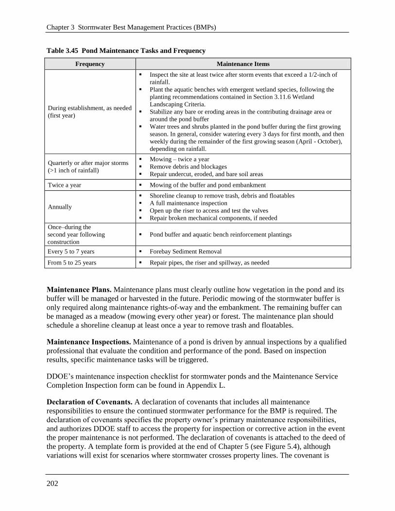
Chapter 3 Stormwater Best Management Practices (BMPs)
202
Table 3.45 Pond Maintenance Tasks and Frequency
Frequency Maintenance Items
During establishment, as needed
(first year)
Inspect the site at least twice after storm events that exceed a 1/2-inch of
rainfall.
Plant the aquatic benches with emergent wetland species, following the
planting recommendations contained in Section 3.11.6 Wetland
Landscaping Criteria.
Stabilize any bare or eroding areas in the contributing drainage area or
around the pond buffer
Water trees and shrubs planted in the pond buffer during the first growing
season. In general, consider watering every 3 days for first month, and then
weekly during the remainder of the first growing season (April - October),
depending on rainfall.
Quarterly or after major storms
(>1 inch of rainfall)
Mowing – twice a year
Remove debris and blockages
Repair undercut, eroded, and bare soil areas
Twice a year Mowing of the buffer and pond embankment
Annually
Shoreline cleanup to remove trash, debris and floatables
A full maintenance inspection
Open up the riser to access and test the valves
Repair broken mechanical components, if needed
Once–during the
second year following
construction
Pond buffer and aquatic bench reinforcement plantings
Every 5 to 7 years Forebay Sediment Removal
From 5 to 25 years Repair pipes, the riser and spillway, as needed
Maintenance Plans. Maintenance plans must clearly outline how vegetation in the pond and its
buffer will be managed or harvested in the future. Periodic mowing of the stormwater buffer is
only required along maintenance rights-of-way and the embankment. The remaining buffer can
be managed as a meadow (mowing every other year) or forest. The maintenance plan should
schedule a shoreline cleanup at least once a year to remove trash and floatables.
Maintenance Inspections. Maintenance of a pond is driven by annual inspections by a qualified
professional that evaluate the condition and performance of the pond. Based on inspection
results, specific maintenance tasks will be triggered.
DDOE’s maintenance inspection checklist for stormwater ponds and the Maintenance Service
Completion Inspection form can be found in Appendix L.
Declaration of Covenants. A declaration of covenants that includes all maintenance
responsibilities to ensure the continued stormwater performance for the BMP is required. The
declaration of covenants specifies the property owner’s primary maintenance responsibilities,
and authorizes DDOE staff to access the property for inspection or corrective action in the event
the proper maintenance is not performed. The declaration of covenants is attached to the deed of
the property. A template form is provided at the end of Chapter 5 (see Figure 5.4), although
variations will exist for scenarios where stormwater crosses property lines. The covenant is

3.10 Ponds
203
between the property and the Government of the District of Columbia. It is submitted through the
Office of the Attorney General. All SWMPs have a maintenance agreement stamp that must be
signed for a building permit to proceed. A maintenance schedule must appear on the SWMP.
Additionally, a maintenance schedule is required in Exhibit C of the declaration of covenants.
Covenants are not required on government properties, but maintenance responsibilities must be
defined through a partnership agreement or a memorandum of understanding.
Waste Material. Waste material from the repair, maintenance, or removal of a BMP or land
cover shall be removed and disposed of in compliance with applicable federal and District law.
3.10.8 Pond Stormwater Compliance Calculations
Stormwater ponds receive 10 percent retention value and are an accepted total suspended solids
(TSS) treatment practice for the amount of storage volume (Sv) provided by the BMP (Table
3.46).
Table 3.46 Pond Retention Value and Pollutant Removal
Retention Value = 0.1 × Sv
Accepted TSS Treatment Practice Yes
3.10.9 References
Cappiella, K., T. Schueler and T. Wright. 2006. Urban Watershed Forestry Manual: Part 2:
Conserving and Planting Trees at Development Sites. USDA Forest Service. Center for
Watershed Protection. Ellicott City, MD.
Hunt, W., C. Apperson, and W. Lord. 2005. ―Mosquito Control for Stormwater Facilities.‖
Urban Waterways. North Carolina State University and North Carolina Cooperative
Extension. Raleigh, NC.
Hunt, W., M. Burchell, J. Wright and K. Bass. 2007. ―Stormwater Wetland Design Update:
Zones, Vegetation, Soil and Outlet Guidance.‖ Urban Waterways. North Carolina State
Cooperative Extension Service. Raleigh, NC.
Ladd, B and J. Frankenburg. 2003. Management of Ponds, Wetlands and Other Water
Reservoirs. Purdue Extension. WQ-41-W.
Mallin, M. 2000. Effect of human development on bacteriological water quality in coastal
watersheds. Ecological Applications 10(4):1047-1056.
Mallin, M.A., S.H. Ensign, Matthew R. McIver, G. Christopher Shank, and Patricia K. Fowler.
2001. Demographic, landscape, and meteorological factors controlling the microbial
pollution of coastal waters. Hydrobiologia 460(1-3):185-193.

Chapter 3 Stormwater Best Management Practices (BMPs)
204
Messersmith, M.J. 2007. Assessing the hydrology and pollutant removal efficiencies of wet
detention ponds in South Carolina. MS. Charleston, S.C. College of Charleston, Master of
Environmental Studies.
Minnesota Stormwater Steering Committee (MSSC). 2005. Minnesota Stormwater Manual.
Emmons & Oliver Resources, Inc. Minnesota Pollution Control Agency. St. Paul, MN.
Santana, F., J. Wood, R. Parsons, and S. Chamberlain. 1994. Control of Mosquito Breeding in
Permitted Stormwater Systems. Southwest Florida Water Management District. Brooksville,
FL.
Schueler, T, 1992. Design of Stormwater Wetland Systems. Metropolitan Washington Council of
Governments. Washington, DC.
Virginia Department of Conservation and Recreation (VA DCR). 1999. Virginia Stormwater
Management Handbook, first edition.
Virginia DCR Stormwater Design Specification No. 14: Wet Ponds Version 1.8. 2010.
Virginia DCR Stormwater Design Specification No. 15: Extended Detention (ED) Pond Version
1.8. 2010.
VA Department of Conservation and Recreation (VA DCR). 1999. Virginia Stormwater
Management Handbook, first edition.

3.11 Wetlands
205
3.11 Wetlands
Definition. Practices that create shallow marsh areas to treat urban stormwater which often
incorporate small permanent pools and/or extended detention storage. Stormwater wetlands are
explicitly designed to provide stormwater detention for larger storms (2-year, 15-year or flood
control events) above the design storm (Stormwater Retention Volume (SWRv)) storage. Design
variants include:
W-1 Shallow wetland
W-2 Extended detention shallow wetland
Stormwater wetlands, sometimes called constructed wetlands, are shallow depressions that
receive stormwater inputs for water quality treatment. Wetlands are typically less than 1 foot
deep (although they have greater depths at the forebay and in micropools) and possess variable
microtopography to promote dense and diverse wetland cover. Runoff from each new storm
displaces runoff from previous storms, and the long residence time allows multiple pollutant
removal processes to operate. The wetland environment provides an ideal environment for
gravitational settling, biological uptake, and microbial activity.
Stormwater wetlands should be considered for use after all other upland retention opportunities
have been exhausted and there is still a remaining treatment volume or runoff from larger storms
(i.e., 2-year, 15-year or flood control events) to manage.
Stormwater wetlands do not receive any stormwater retention value and should be considered
only for management of larger storm events. Stormwater wetlands have both community and
environmental concerns (see Section 3.10.1 Pond Feasibility Criteria) that should be considered
before choosing stormwater ponds for the appropriate stormwater practice on site.
Note: All of the pond performance criteria presented in Section 3.10 also apply to the design of
stormwater wetlands. Additional criteria that govern the geometry and establishment of created
wetlands are presented in this section.

Chapter 3 Stormwater Best Management Practices (BMPs)
206
Figure 3.37 Example of extended detention shallow wetland.

3.11 Wetlands
207
Figure 3.38 Cross section of a typical stormwater wetland.
Figure 3.39 Interior wetland zones: (I) Deep Pool (depth -48 to -18 inches), (II) Transition Zone
(depth -18 to -6 inches), (III and IV) High Marsh Zone (depth -6 to +6 inches), (IV) Temporary
Inundation Area, and (V) Upper Bank (adapted from Hunt et al, 2007).
3.11.1 Wetland Feasibility Criteria
Constructed wetland designs are subject to the following site constraints:
Adequate Water Balance. Wetlands must have enough water supplied from groundwater,
runoff or baseflow so that the permanent pools will not draw down by more than 2 feet after a
30-day summer drought. A simple water balance calculation must be performed using the
equation provided in Section 3.11.4. Wetland Design Criteria.

Chapter 3 Stormwater Best Management Practices (BMPs)
208
Contributing Drainage Area (CDA). The contributing drainage area must be large enough to
sustain a permanent water level within the stormwater wetland. If the only source of wetland
hydrology is stormwater runoff, then several dozen acres of drainage area are typically needed to
maintain constant water elevations. Smaller drainage areas are acceptable if the bottom of the
wetland intercepts the groundwater table or if the designer or approving agency is willing to
accept periodic wetland drawdown.
Space Requirements. Constructed wetlands normally require a footprint that takes up about 3
percent of the contributing drainage area, depending on the average depth of the wetland and the
extent of its deep pool features.
Site Topography. Wetlands are best applied when the grade of contributing slopes is less than 8
percent.
Steep Slopes. A modification of the constructed wetland (and linear wetland or wet swale
system) is the regenerative stormwater conveyance (RSC) or step pool storm conveyance
channel. The RSC can be used to bring stormwater down steeper grades through a series of step
pools. This can serve to bring stormwater down outfalls where steep drops on the edge of the
tidal receiving system can create design challenges. For more information on RSC systems,
designers can consult the Anne Arundel County Design Specifications, available at
http://www.aacounty.org/DPW/Watershed/StepPoolStormConveyance.cfm.
Available Hydraulic Head. The depth of a constructed wetland is usually constrained by the
hydraulic head available on the site. The bottom elevation is fixed by the elevation of the
existing downstream conveyance system to which the wetland will ultimately discharge. Because
constructed wetlands are typically shallow, the amount of head needed (usually a minimum of 2
to 4 feet) is typically less than for wet ponds.
Setbacks. To avoid the risk of seepage, stormwater wetlands must not be hydraulically
connected to structure foundations. Setbacks to structures must be at least 10 feet and adequate
water-proofing protection must be provided for foundations and basements.
Depth to Water Table. The depth to the groundwater table is not a major constraint for
constructed wetlands, since a high water table can help maintain wetland conditions. However,
designers should keep in mind that high groundwater inputs may increase excavation costs (refer
to Section 3.10 Stormwater Ponds).
Soils. Soil tests should be conducted to determine the infiltration rates and other subsurface
properties of the soils underlying the proposed wetland. Highly permeable soils will make it
difficult to maintain a healthy permanent pool. Underlying soils of Hydrologic Soil Group (HSG)
C or D should be adequate to maintain a permanent pool. Most HSG A soils and some HSG B
soils will require a liner (see Table 3.44).
Use of or Discharges to Natural Wetlands. Constructed wetlands may not be located within
jurisdictional waters, including wetlands, without obtaining a Section 404 permit from the
appropriate federal regulatory agency. In addition, designer should investigate the status of
adjacent wetlands to determine if the discharge from the constructed wetland will change the

3.11 Wetlands
209
hydroperiod of a downstream natural wetland (see Cappiella et al., 2006 for guidance on
minimizing stormwater discharges to existing wetlands).
Regulatory Status. Constructed wetlands built for the express purpose of stormwater treatment
are generally not considered jurisdictional wetlands.
Perennial Streams. Locating a constructed wetland along or within a perennial stream will
require both Section 401 and Section 404 permits from the state or federal regulatory authority.
Community and Environmental Concerns. In addition to the community and environmental
concerns that exist for stormwater ponds, stormwater wetlands can generate the following to be
addressed during design:
Aesthetics and Habitat. Constructed wetlands can create wildlife habitat and can also
become an attractive community feature. Designers should think carefully about how the
wetland plant community will evolve over time, since the future plant community seldom
resembles the one initially planted.
Existing Forests. Given the large footprint of a constructed wetland, there is a strong chance
that the construction process may result in extensive tree clearing. The designer should
preserve mature trees during the facility layout, and he/she may consider creating a wooded
wetland (see Cappiella et al., 2006). In the District of Columbia a permit is required to
remove a tree with a circumference greater than 55-inches on private lands. A permit is
required to prune or remove any street tree between the sidewalk and the curb. These permits
are issued by the District Department of Transportation, Urban Forestry Administration
(UFA).
Safety Risk. Constructed wetlands are safer than other types of ponds, although forebays and
micropools must be designed with aquatic benches to reduce safety risks.
Mosquito Risk. Mosquito control can be a concern for stormwater wetlands if they are
under-sized or have a small contributing drainage area. Deepwater zones serve to keep
mosquito populations in check by providing habitat for fish and other pond life that prey on
mosquito larvae. Few mosquito problems are reported for well designed, properly sized and
frequently maintained constructed wetlands; however, no design can eliminate them
completely. Simple precautions can be taken to minimize mosquito breeding habitat within
constructed wetlands (e.g., constant inflows, benches that create habitat for natural predators,
and constant pool elevations—MSSC, 2005).
3.11.2 Wetland Conveyance Criteria
The slope profile within individual wetland cells should generally be flat from inlet to outlet
(adjusting for microtopography). The recommended maximum elevation drop between
wetland cells is 1 foot or less.
Since most constructed wetlands are on-line facilities, they need to be designed to safely pass
the maximum design storm (e.g., the 15-year and 100-year design storms). While the
ponding depths for the more frequent 2-year storm are limited in order to avoid adverse
impacts to the planting pallet, the overflow for the less frequent 15- and 100-year storms

Chapter 3 Stormwater Best Management Practices (BMPs)
210
must likewise be carefully designed to minimize the depth of ponding. A maximum depth of
4 feet over the wetland pool is recommended.
While many different options are available for setting the normal pool elevation, it is strongly
recommended that removable flashboard risers be used, given their greater operational
flexibility to adjust water levels following construction (see Hunt et al, 2007). Also, a weir
can be designed to accommodate passage of the larger storm flows at relatively low ponding
depths.
3.11.3 Wetland Pretreatment Criteria
Sediment regulation is critical to sustain stormwater wetlands. Consequently, a forebay shall be
located at the inlet, and a micropool shall be located at the outlet (A micropool is a three to six
foot deep pool used to protect the low-flow pipe from clogging and to prevent sediment
resuspension). Forebays are designed in the same manner as stormwater ponds (see Section
3.10.3 Pond Pretreatment Criteria). The design of forebays should consider the possibility of
heavy trash loads from public areas.
3.11.4 Wetland Design Criteria
Internal Design Geometry. Research and experience have shown that the internal design
geometry and depth zones are critical in maintaining the pollutant removal capability and plant
diversity of stormwater wetlands. Wetland performance is enhanced when the wetland has
multiple cells, longer flowpaths, and a high ratio of surface area to volume. Whenever possible,
constructed wetlands should be irregularly shaped with long, sinuous flow paths. The following
design elements are required for stormwater wetlands:
Multiple-Cell Wetlands. Wetlands can be divided into at least four internal sub-cells of
different elevations: the forebay, a micro-pool outlet, and two additional cells. Cells can be
formed by sand berms (anchored by rock at each end), back-filled coir fiber logs, or forested
peninsulas (extending as wedges across 95 percent of the wetland width). The vegetative target is
to ultimately achieve a 50-50 mix of emergent and forested wetland vegetation within all four
cells.
The first cell (the forebay) is deeper and is used to receive runoff from the pond cell or the
inflow from a pipe or open channel and distribute it as sheetflow into successive wetland cells.
The surface elevation of the second cell is the normal pool elevation. It may contain a forested
island or a sand wedge channel to promote flows into the third cell, which is 3 to 6 inches lower
than the normal pool elevation. The purpose of the wetland cells is to create an alternating
sequence of aerobic and anaerobic conditions to maximize pollutant removal. The fourth wetland
cell is located at the discharge point and serves as a micro-pool with an outlet structure or weir.
Extended Detention Ponding Depth. When extended detention is provided for management of
larger storm events, the total ED volume shall not comprise more than 50 percent of the total
volume stored by the wetland, and its maximum water surface elevation shall not extend more
than three feet above the normal pool.
Deep Pools. Approximately 25 percent of the wetland surface area must be provided in at least
three deeper pools—located at the inlet (forebay), center, and outlet (micropool) of the

3.11 Wetlands
211
wetland—with each pool having a depth of from 18 to 48 inches. Refer to the sizing based on
water balance below for additional guidance on the minimum depth of the deep pools.
High Marsh Zone. Approximately 70 percent of the wetland surface area must exist in the high
marsh zone (-6 inches to +6 inches, relative to the normal pool elevation).
Transition Zone. The low marsh zone is no longer an acceptable wetland zone, and is only
allowed as a short transition zone from the deeper pools to the high marsh zone(-6 to -18 inches
below the normal pool elevation). In general, this transition zone should have a maximum slope
of 5H:1V (or preferably flatter) from the deep pool to the high marsh zone. It is advisable to
install biodegradable erosion control fabrics or similar materials during construction to prevent
erosion or slumping of this transition zone.
Flow Path. In terms of the flow path, there are two design objectives:
The overall flow path through the wetland can be represented as the length-to-width ratio OR
the flow path ratio. A minimum overall flow path of 2:1 must be provided across the
stormwater wetland.
The shortest flow path represents the distance from the closest inlet to the outlet. The ratio of
the shortest flow path to the overall length must be at least 0.5. In some cases – due to site
geometry, storm sewer infrastructure, or other factors—some inlets may not be able to meet
these ratios. However, the drainage area served by these ―closer‖ inlets must constitute no
more than 20 percent of the total contributing drainage area.
Side Slopes. Side slopes for the wetland should generally have gradients of 4H:1V or flatter.
These mild slopes promote better establishment and growth of the wetland vegetation. They also
contribute to easier maintenance and a more natural appearance.
Micro-Topographic Features. Stormwater wetlands must have internal structures that create
variable micro-topography, which is defined as a mix of above-pool vegetation, shallow pools,
and deep pools that promote dense and diverse vegetative cover.
Constructed Wetland Material Specifications. Wetlands are generally constructed with
materials obtained on-site, except for the plant materials, inflow and outflow devices (e.g., piping
and riser materials), possibly stone for inlet and outlet stabilization, and geotextile fabric for
lining banks or berms. Plant stock should be nursery grown, unless otherwise approved, and
must be healthy and vigorous native species free from defects, decay, disfiguring roots, sun-
scald, injuries, abrasions, diseases, insects, pests, and all forms of infestations or objectionable
disfigurements, as determined by DDOE.
Wetland Sizing. Constructed wetlands can be designed to capture and treat the remaining
stormwater discharged from upstream practices from the design storm (SWRv). Additionally,
wetlands can be sized to control peak flow rates from the 2-year and 15-year frequency storm
event or other design storm. Design calculations must ensure that the post-development peak
discharge does not exceed the predevelopment peak discharge. See Section 2.7 Hydrology
Methods for a summary of acceptable hydrological methodologies and models.
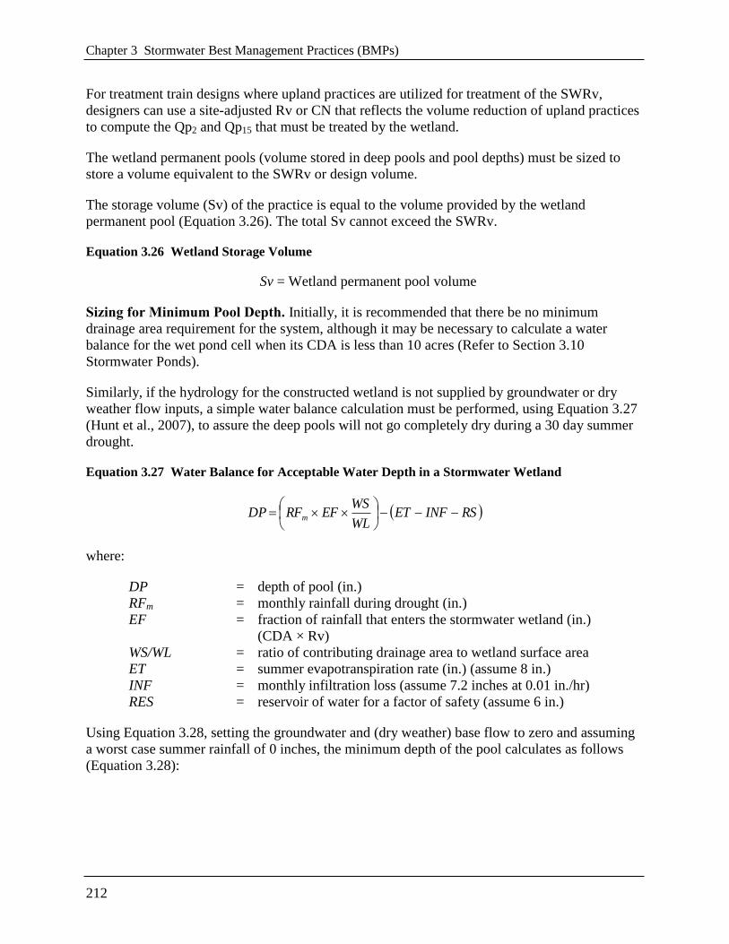
Chapter 3 Stormwater Best Management Practices (BMPs)
212
For treatment train designs where upland practices are utilized for treatment of the SWRv,
designers can use a site-adjusted Rv or CN that reflects the volume reduction of upland practices
to compute the Qp2 and Qp15 that must be treated by the wetland.
The wetland permanent pools (volume stored in deep pools and pool depths) must be sized to
store a volume equivalent to the SWRv or design volume.
The storage volume (Sv) of the practice is equal to the volume provided by the wetland
permanent pool (Equation 3.26). The total Sv cannot exceed the SWRv.
Equation 3.26 Wetland Storage Volume
Sv = Wetland permanent pool volume
Sizing for Minimum Pool Depth. Initially, it is recommended that there be no minimum
drainage area requirement for the system, although it may be necessary to calculate a water
balance for the wet pond cell when its CDA is less than 10 acres (Refer to Section 3.10
Stormwater Ponds).
Similarly, if the hydrology for the constructed wetland is not supplied by groundwater or dry
weather flow inputs, a simple water balance calculation must be performed, using Equation 3.27
(Hunt et al., 2007), to assure the deep pools will not go completely dry during a 30 day summer
drought.
Equation 3.27 Water Balance for Acceptable Water Depth in a Stormwater Wetland
RSINFETWL
WSEFRFDP m
where:
DP = depth of pool (in.)
RFm = monthly rainfall during drought (in.)
EF = fraction of rainfall that enters the stormwater wetland (in.)
(CDA × Rv)
WS/WL = ratio of contributing drainage area to wetland surface area
ET = summer evapotranspiration rate (in.) (assume 8 in.)
INF = monthly infiltration loss (assume 7.2 inches at 0.01 in./hr)
RES = reservoir of water for a factor of safety (assume 6 in.)
Using Equation 3.28, setting the groundwater and (dry weather) base flow to zero and assuming
a worst case summer rainfall of 0 inches, the minimum depth of the pool calculates as follows
(Equation 3.28):

3.11 Wetlands
213
Equation 3.28 Minimum Depth of the Permanent Pool
Depth of Pool (DP) = 0 in. (RFm) – 8 in. (ET) – 7.2 in. (INF) – 6 in. (RES) = 21.2 in.
Therefore, unless there is other input, such as base flow or groundwater, the minimum depth of
the pool should be at least 22 inches (rather than the 18-inch minimum depth noted in Section
3.11.4 and depicted in Figure 3.39).
3.11.5 Wetland Construction Sequence
The construction sequence for stormwater wetlands depends on site conditions, design
complexity, and the size and configuration of the proposed facility. The following two-stage
construction sequence is recommended for installing an on-line wetland facility and establishing
vigorous plant cover.
Stage 1 Construction Sequence: Wetland Facility Construction.
Step 1: Stabilize Drainage Area. Stormwater wetlands should only be constructed after the
contributing drainage area to the wetland is completely stabilized. If the proposed wetland site
will be used as a sediment trap or basin during the construction phase, the construction notes
must clearly indicate that the facility will be de-watered, dredged and re-graded to design
dimensions after the original site construction is complete.
Step 2: Assemble Construction Materials On-site. Inspect construction materials to insure
they conform to design specifications, and prepare any staging areas.
Step 3: Clear and Strip. Bring the project area to the desired sub-grade.
Step 4: Install Soil Erosion and Sediment Control Measures prior to construction,
including sediment basins and stormwater diversion practices. All areas surrounding the wetland
that are graded or denuded during construction of the wetland are to be planted with turf grass,
native plant materials or other approved methods of soil stabilization. Grass sod is preferred over
seed to reduce seed colonization of the wetland. During construction the wetland must be
separated from the contributing drainage area so that no sediment flows into the wetland areas. In
some cases, a phased or staged soil erosion and sediment control plan (SESCP) may be
necessary to divert flow around the stormwater wetland area until installation and stabilization
are complete.
Step 5: Excavate the Core Trench for the Embankment and Install the Spillway Pipe.
Step 6: Install the Riser or Outflow Structure and ensure that the top invert of the overflow
weir is constructed level and at the proper design elevation (flashboard risers are strongly
recommended by Hunt et al, 2007).
Step 7: Construct the Embankment and any Internal Berms in 8 to 12-inch lifts and
compacted with appropriate equipment.
Step 8: Excavate and Grade. Survey to achieve the appropriate elevation and designed
contours for the bottom and side slopes of the wetland. This is normally done by ―roughing up‖
the interim elevations with a skid loader or other similar equipment to achieve the desired
Chapter 3 Stormwater Best Management Practices (BMPs)
214
topography across the wetland. Spot surveys should be made to ensure that the interim elevations
are 3 to 6 inches below the final elevations for the wetland.
Step 9: Install Micro-Topographic Features and Soil Amendments within wetland area.
Since most stormwater wetlands are excavated to deep sub-soils, they often lack the nutrients
and organic matter needed to support vigorous growth of wetland plants. It is therefore essential
to add sand, compost, topsoil or wetland mulch to all depth zones in the wetland. The importance
of soil amendments in excavated wetlands cannot be over-emphasized; poor survival and future
wetland coverage are likely if soil amendments are not added. The planting soil should be a high
organic content loam or sandy loam, placed by mechanical methods, and spread by hand.
Planting soil depth should be at least 4 inches for shallow wetlands. No machinery should be
allowed to traverse over the planting soil during or after construction. Planting soil should be
tamped as directed in the design specifications, but it should not be overly compacted. After the
planting soil is placed, it should be saturated and allowed to settle for at least one week prior to
installation of plant materials.
Step 10: Construct the Emergency Spillway. The emergency spillway must be constructed in
cut or structurally stabilized soils.
Step 11: Install Outlet Pipes. The installation of outlet pipes must include a the downstream
rip-rap protection apron.
Step 12: Stabilize Exposed Soils with temporary seed mixtures appropriate for a wetland
environment. All wetland features above the normal pool elevation should be temporarily
stabilized by hydro-seeding or seeding over straw.
Stage 2 Construction Sequence: Establishing the Wetland Vegetation.
Step 13: Finalize the Wetland Landscaping Plan. At this stage the engineer, landscape
architect, and wetland expert work jointly to refine the initial wetland landscaping plan after the
stormwater wetland has been constructed. Several weeks of standing time is needed so that the
designer can more precisely predict the following two things:
Where the inundation zones are located in and around the wetland; and
Whether the final grade and wetland microtopography will persist over time.
This allows the designer to select appropriate species and additional soil amendments, based on
field confirmation of soils properties and the actual depths and inundation frequencies occurring
within the wetland.
Step 14: Open Up the Wetland Connection. Once the final grades are attained, the pond
and/or contributing drainage area connection should be opened to allow the wetland cell to fill up
to the normal pool elevation. Gradually inundate the wetland erosion of unplanted features.
Inundation must occur in stages so that deep pool and high marsh plant materials can be placed
effectively and safely. Wetland planting areas should be at least partially inundated during
planting to promote plant survivability.
3.11 Wetlands
215
Step 15: Measure and Stake Planting Depths at the onset of the planting season. Depths in
the wetland should be measured to the nearest inch to confirm the original planting depths of the
planting zone. At this time, it may be necessary to modify the plan to reflect altered depths or a
change in the availability of wetland plant stock. Surveyed planting zones should be marked on
the as-built or design plan, and their locations should also be identified in the field, using stakes
or flags.
Step 16: Propagate the Stormwater Wetland. Three techniques are used in combination to
propagate the emergent community over the wetland bed:
1. Initial Planting of Container-Grown Wetland Plant Stock. The transplanting window
extends from early April to mid-June. Planting after these dates is quite chancy, since
emergent wetland plants need a full growing season to build the root reserves needed to get
through the winter. It is recommended that plants be ordered at least 6 months in advance to
ensure the availability and on-time delivery of desired species.
2. Broadcasting Wetland Seed Mixes. The higher wetland elevations should be established by
broadcasting wetland seed mixes to establish diverse emergent wetlands. Seeding of
switchgrass or wetland seed mixes as a ground cover is recommended for all zones above 3
inches below the normal pool elevation. Hand broadcasting or hydroseeding can be used to
spread seed, depending on the size of the wetland cell.
3. Allowing “Volunteer Wetland Plants to Establish on Their Own. The remaining areas of
the stormwater wetland will eventually (within 3 to 5 years) be colonized by volunteer
species from upstream or the forest buffer.
Step 17: Install Goose Protection to Protect Newly Planted or Newly Growing Vegetation. This is particularly critical for newly established emergents and herbaceous plants, as predation
by Canada geese can quickly decimate wetland vegetation. Goose protection can consist of
netting, webbing, or string installed in a crisscross pattern over the surface area of the wetland,
above the level of the emergent plants.
Step 18: Plant the Wetland Fringe and Buffer Area. This zone generally extends from 1 to
3 feet above the normal pool elevation (from the shoreline fringe to about half of the maximum
water surface elevation for the 2-year storm). Consequently, plants in this zone are infrequently
inundated (5 to 10 times per year), and must be able to tolerate both wet and dry periods.
Construction Supervision. Supervision during construction is recommended to ensure that
stormwater wetlands are properly constructed and established. Multiple site visits and
inspections by a qualified professional are recommended during the following stages of the
wetland construction process:
Preconstruction meeting
Initial site preparation including the installation of project soil erosion and sediment control
measures
Excavation/Grading (e.g., interim/final elevations)
Wetland installation (e.g., microtopography, soil amendments and staking of planting zones)

Chapter 3 Stormwater Best Management Practices (BMPs)
216
Planting Phase (with an experienced landscape architect or wetland expert)
Final Inspection (develop a punch list for facility acceptance)
DDOE’s construction phase inspection checklist for Constructed Wetlands can be found in
Appendix K.
3.11.6 Wetland Landscaping Criteria
An initial wetland landscaping plan is required for any stormwater wetland and should be jointly
developed by the engineer and a wetlands expert or experienced landscape architect. The plan
should outline a detailed schedule for the care, maintenance and possible reinforcement of
vegetation in the wetland and its buffer for up to 10 years after the original planting.
The plan should outline a realistic, long-term planting strategy to establish and maintain desired
wetland vegetation. The plan should indicate how wetland plants will be established within each
inundation zone (e.g., wetland plants, seed-mixes, volunteer colonization, and tree and shrub
stock) and whether soil amendments are needed to get plants started. At a minimum, the plan
should contain the following:
Plan view(s) with topography at a contour interval of no more than 1 foot and spot elevations
throughout the cell showing the wetland configuration, different planting zones (e.g., high
marsh, deep water, upland), microtopography, grades, site preparation, and construction
sequence.
A plant schedule and planting plan specifying emergent, perennial, shrub and tree species,
quantity of each species, stock size, type of root stock to be installed, and spacing. To the
degree possible, the species list for the constructed wetland should contain plants found in
similar local wetlands.
The following general guidance is provided:
Use Native Species Where Possible. Table 3.47 provides a list of common native shrub and
tree species and Table 3.48 provides a list of common native emergent, submergent and
perimeter plant species, all of which have proven to do well in stormwater wetlands in the
mid-Atlantic region and are generally available from most commercial nurseries (consult
DDOE’s webpage for information on area suppliers). Other native species can be used that
appear in state-wide plant lists. The use of native species is strongly encouraged, but in some
cases, non-native ornamental species may be added as long as they are not invasive. Invasive
species such as cattails, Phragmites and purple loosestrife must not be planted.
Match Plants to Inundation Zones. The various plant species shown in Table 3.47 and
Table 3.48 should be matched to the appropriate inundation zone. The first four inundation
zones are particularly applicable to stormwater wetlands, as follows:
Zone 1 -6 inches to -12 inches below the normal pool elevation
Zone 2 -6 inches to the normal pool elevation
Zone 3 From the normal pool elevation to + 12 inches above it
Zone 4 +12 inches to + 36 inches above the normal pool elevation (i.e., above ED Zone)

3.11 Wetlands
217
Note: The Low Marsh Zone (-6 inches to -18 inches below the normal pool elevation) has
been dropped since experience has shown that few emergent wetland plants flourish in this
deeper zone.
Aggressive Colonizers. To add diversity to the wetland, 5 to 7 species of emergent wetland
plants should be planted, using at least four emergent species designated as aggressive
colonizers (shown in bold in Table 3.48). No more than 25 percent of the high marsh wetland
surface area needs to be planted. If the appropriate planting depths are achieved, the entire
wetland should be colonized within three years. Individual plants should be planted 18 inches
on center within each single species ―cluster‖.
Table 3.47 Popular, Versatile, and Available Native Trees and Shrubs for Constructed Wetlands
Shrubs Trees
Common and Scientific Names Zone1 Common and Scientific Names Zone
1
Button Bush
(Cephalanthus occidentalis)
2, 3 Atlantic White Cedar
(Charnaecyparis thyoides)
2, 3
Common Winterberry
(Ilex verticillatta)
3, 4 Bald Cypress
(Taxodium distichum)
2, 3
Elderberry
(Sambucus canadensis)
3 Black Willow
(Salix nigra)
3, 4
Indigo Bush
(Amorpha fruticosa)
3 Box Elder
(Acer Negundo)
2, 3
Inkberry
(Ilex glabra)
2, 3 Green Ash
(Fraxinus pennsylvanica)
3, 4
Smooth Alder
(Alnus serrulata)
2, 3 Grey Birch
(Betula populifolia)
3, 4
Spicebush
(Lindera benzoin)
3, 4 Red Maple
(Acer rubrum)
3, 4
Swamp Azalea
(Azalea viscosum)
2, 3 River Birch
(Betula nigra)
3, 4
Swamp Rose
(Rosa palustris)
2, 3 Swamp Tupelo
(Nyssa biflora)
2, 3
Sweet Pepperbush
(Clethra ainifolia)
2, 3 Sweetbay Magnolia
(Magnolia virginiana)
3, 4
Sweetgum
(Liquidambar styraciflua)
3, 4
Sycamore
(Platanus occidentalis)
3, 4
Water Oak
(Quercus nigra)
3, 4
Willow Oak
(Quercus phellos)
3,4
1Zone 1: -6 inches to -12 inches OR -18 inches below the normal pool elevation
Zone 2: -6 inches to the normal pool elevation
Zone 3: From the normal pool elevation to +12 inches
Zone 4: +12 inches to +36 inches; above ED zone
Source: Virginia DCR Stormwater Design Specification No. 13: Constructed Wetlands Version 1.8. 2010.

Chapter 3 Stormwater Best Management Practices (BMPs)
218
Table 3.48 Popular, Versatile, and Available Native Emergent and Submergent Vegetation for
Constructed Wetlands
Plant Zone1 Form Inundation
Tolerance
Wildlife Value Notes
Arrow Arum
(Peltandra virginica)
2 Emergent Up to 1 ft High; berries are
eaten by wood
ducks
Full sun to partial
shade
Broad-Leaf Arrowhead
(Duck Potato)
(Saggitaria latifolia)
2 Emergent Up to 1 ft Moderate; tubers
and seeds eaten by
ducks
Aggressive colonizer
Blueflag Iris*
(Iris versicolor)
2, 3 Emergent Up to 6 in. Limited Full sun (to flower) to
partial shade
Broomsedge
(Andropogon
virginianus)
2, 3 Perimeter Up to 3 in. High; songbirds and
browsers; winter
food and cover
Tolerant of fluctuating
water levels and
partial shade
Bulltongue Arrowhead
(Sagittaria lancifolia) 2, 3 Emergent 0–24 in. Waterfowl, small
mammals
Full sun to partial
shade
Burreed
(Sparganium
americanum)
2, 3 Emergent 0–6 in. Waterfowl, small
mammals
Full sun to partial shad
Cardinal Flower *
(Lobelia cardinalis)
3 Perimeter Periodic
inundation
Attracts
hummingbirds
Full sun to partial
shade
Common Rush
(Juncus spp.) 2, 3 Emergent Up to 12 in. Moderate; small
mammals,
waterfowl,
songbirds
Full sun to partial
shade
Common Three Square
(Scipus pungens) 2 Emergent Up to 6 in. High; seeds, cover,
waterfowl,
songbirds
Fast colonizer; can
tolerate periods of
dryness; full sun; high
metal removal
Duckweed
(Lemna sp.
1, 2 Submerge
nt /
Emergent
Yes High; food for
waterfowl and fish
May biomagnify
metals beyond
concentrations found
in the water
Joe Pye Weed
(Eupatorium purpureum)
2, 3 Emergent Drier than
other Joe-Pye
Weeds; dry to
moist areas;
periodic
inundation
Butterflies,
songbirds, insects
Tolerates all light
conditions
Lizard’s Tail
(Saururus cernus) 2 Emergent Up to 1 ft Low; except for
wood ducks
Rapid growth; shade-
tolerant
Marsh Hibiscus
(Hibiscus moscheutos)
2, 3 Emergent Up to 3 in. Low; nectar Full sun; can tolerate
periodic dryness
Pickerelweed
(Pontederia cordata) 2, 3 Emergent Up to 1 ft Moderate; ducks,
nectar for butterflies
Full sun to partial
shade
Pond Weed
(Potamogeton
pectinatus)
1 Submerge
nt
Yes Extremely high;
waterfowl, marsh
and shore birds
Removes heavy metals
from the water
Rice Cutgrass
(Leersia oryzoides)
2, 3 Emergent Up to 3 in. High; food and
cover
Prefers full sun,
although tolerant of
shade; shoreline
stabilization

3.11 Wetlands
219
Plant Zone1 Form Inundation
Tolerance
Wildlife Value Notes
Sedges
(Carex spp.) 2, 3 Emergent Up to 3 in. High; waterfowl,
songbirds
Wetland and upland
species
Softstem Bulrush
(Scipus validus) 2, 3 Emergent Up to 2 ft Moderate; good
cover and food
Full sun; aggressive
colonizer; high
pollutant removal
Smartweed
(Polygonum spp.) 2 Emergent Up to 1 ft High; waterfowl,
songbirds; seeds and
cover
Fast colonizer; avoid
weedy aliens, such as
P. Perfoliatum
Spatterdock
(Nuphar luteum) 2 Emergent Up to 1.5 ft Moderate for food,
but High for cover
Fast colonizer; tolerant
of varying water levels
Switchgrass
(Panicum virgatum)
2, 3, 4 Perimeter Up to 3 in. High; seeds, cover;
waterfowl,
songbirds
Tolerates wet/dry
conditions
Sweet Flag *
(Acorus calamus)
2, 3 Perimeter Up to 3 in. Low; tolerant of dry
periods
Tolerates acidic
conditions; not a rapid
colonizer
Waterweed
(Elodea canadensis)
1 Submerge
nt
Yes Low Good water
oxygenator; high
nutrient, copper,
manganese and
chromium removal
Wild celery
(Valisneria americana)
1 Submerge
nt
Yes High; food for
waterfowl; habitat
for fish and
invertebrates
Tolerant of murkey
water and high
nutrient loads
Wild Rice
(Zizania aquatica)
2 Emergent Up to 1 ft High; food, birds Prefers full sun
Woolgrass
(Scirpus cyperinus) 3, 4 Emergent yes High: waterfowl,
small mammals
Fresh tidal and non-
tidal, swamps, forested
wetlands, meadows,
ditches 1Zone 1: -6 inches to -12 inches OR -18 inches below the normal pool elevation
Zone 2: -6 inches to the normal pool elevation
Zone 3: From the normal pool elevation to +12 inches
Zone 4: +12 inches to +36 inches; above ED zone
*Not a major colonizer, but adds color (Aggressive colonizers are shown in bold type)
Source: Virginia DCR Stormwater Design Specification No. 13: Constructed Wetlands Version 1.8. 2010.
Suitable Tree Species. The major shift in stormwater wetland design is to integrate trees and
shrubs into the design, in tree islands, peninsulas, and fringe buffer areas. Deeper-rooted
trees and shrubs that can extend to the stormwater wetland’s local water table are important
for creating a mixed wetland community. Table 3.47 above presents some recommended tree
and shrub species in the mid-Atlantic region for different inundation zones. A good planting
strategy includes varying the size and age of the plant stock to promote a diverse structure.
Using locally grown container or bare root stock is usually the most successful approach, if
planting in the spring. It is recommended that buffer planting areas be over-planted with a
small stock of fast growing successional species to achieve quick canopy closure and shade
out invasive plant species. Trees may be planted in clusters to share rooting space on

Chapter 3 Stormwater Best Management Practices (BMPs)
220
compacted wetland side-slopes. Planting holes should be amended with compost (a 2:1 ratio
of loose soil to compost) prior to planting.
Pre- and Post-Nursery Care. Plants should be kept in containers of water or moist
coverings to protect their root systems and keep them moist when in transporting them to the
planting location. As much as six to nine months of lead time may be needed to fill orders for
wetland plant stock from aquatic plant nurseries. Consult DDOE’s webpage for information
on area suppliers.
3.11.7 Wetland Maintenance Criteria
Successful establishment of constructed wetland areas requires that the following tasks be
undertaken in the first two years:
Initial Inspections. During the first 6 months following construction, the site should be
inspected by a qualified professional at least twice after storm events that exceed 1/2 inch of
rainfall.
Spot Reseeding. Inspections should include looking for bare or eroding areas in the
contributing drainage area or around the wetland buffer, and make sure they are immediately
stabilized with grass cover.
Watering. Trees planted in the buffer and on wetland islands and peninsulas need watering
during the first growing season. In general, consider watering every three days for first
month, and then weekly during the first growing season (April - October), depending on
rainfall.
Reinforcement Plantings. Regardless of the care taken during the initial planting of the
wetland and buffer, it is probable that some areas will remain unvegetated and some species
will not survive. Poor survival can result from many unforeseen factors, such as predation,
poor quality plant stock, water level changes, drought. Thus, it is advisable to budget for an
additional round of reinforcement planting after one or two growing seasons. Construction
contracts should include a care and replacement warranty extending at least two growing
seasons after initial planting, to selectively replant portions of the wetland that fail to fill in or
survive. If a minimum coverage of 50 percent is not achieved in the planted wetland zones
after the second growing season, a reinforcement planting will be required.
Managing vegetation is an important ongoing maintenance task at every constructed wetland and
for each inundation zone. Following the design criteria above should result in a reduced need for
regular mowing of the embankment and access roads. Vegetation within the wetland, however,
will require some annual maintenance.
Designers should expect significant changes in wetland species composition to occur over time.
Inspections should carefully track changes in wetland plant species distribution over time.
Invasive plants should be dealt with as soon as they begin to colonize the wetland. As a general
rule, control of undesirable invasive species (e.g., cattails and Phragmites) should commence
when their coverage exceeds more than 15 percent of a wetland cell area. Although the
application of herbicides is not recommended, some types (e.g., Glyphosate) have been used to
control cattails with some success. Extended periods of dewatering may also work, since early
manual removal provides only short-term relief from invasive species. While it is difficult to

3.11 Wetlands
221
exclude invasive species completely from stormwater wetlands, their ability to take over the
entire wetland can be reduced if the designer creates a wide range of depth zones and a complex
internal structure within the wetland.
Thinning or harvesting of excess forest growth may be periodically needed to guide the forested
wetland into a more mature state. Vegetation may need to be harvested periodically if the
constructed wetland becomes overgrown. Thinning or harvesting operations should be scheduled
to occur approximately 5 and 10 years after the initial wetland construction. Removal of woody
species on or near the embankment and maintenance access areas should be conducted every 2
years.
Designers should refer to Section 3.10.7 Pond Maintenance Criteria for additional maintenance
responsibilities associated with wetlands. Ideally, maintenance of constructed wetlands should be
driven by annual inspections by a qualified professional that evaluate the condition and
performance of the wetland. Based on inspection results, specific maintenance tasks will be
triggered. DDOE’s maintenance inspection checklist for stormwater wetlands and the
Maintenance Service Completion Inspection form can be found in Appendix L.
Declaration of Covenants. A declaration of covenants that includes all maintenance
responsibilities to ensure the continued stormwater performance for the BMP is required. The
declaration of covenants specifies the property owner’s primary maintenance responsibilities,
and authorizes DDOE staff to access the property for inspection or corrective action in the event
the proper maintenance is not performed. The declaration of covenants is attached to the deed of
the property. A template form is provided at the end of Chapter 5 (see Figure 5.4), although
variations will exist for scenarios where stormwater crosses property lines. The covenant is
between the property and the Government of the District of Columbia. It is submitted through the
Office of the Attorney General. All SWMPs have a maintenance agreement stamp that must be
signed for a building permit to proceed. A maintenance schedule must appear on the SWMP.
Additionally, a maintenance schedule is required in Exhibit C of the declaration of covenants.
Covenants are not required on government properties, but maintenance responsibilities must be
defined through a partnership agreement or a memorandum of understanding.
Waste Material. Waste material from the repair, maintenance, or removal of a BMP or land
cover shall be removed and disposed of in compliance with applicable federal and District law.
3.11.8 Wetland Stormwater Compliance Calculations
Stormwater wetlands receive 10 percent retention value and are an accepted total suspended
solids (TSS) treatment practice for the amount of storage volume (Sv) provided by the BMP
(Table 3.49).
Table 3.49 Wetland Retention Value and Pollutant Removal
Retention Value = 0.1 × Sv
Accepted TSS Treatment Practice Yes

Chapter 3 Stormwater Best Management Practices (BMPs)
222
3.11.9 References
Cappiella, K., T. Schueler and T. Wright. 2006. Urban Watershed Forestry Manual: Part 2:
Conserving and Planting Trees at Development Sites. USDA Forest Service. Center for
Watershed Protection. Ellicott City, MD.
Hunt, W., M. Burchell, J. Wright and K. Bass. 2007. ―Stormwater Wetland Design Update:
Zones, Vegetation, Soil and Outlet Guidance.‖ Urban Waterways. North Carolina State
Cooperative Extension Service. Raleigh, NC.
Minnesota Stormwater Steering Committee (MSSC). 2005. Minnesota Stormwater Manual.
Emmons & Oliver Resources, Inc. Minnesota Pollution Control Agency. St. Paul, MN.
Virginia DCR Stormwater Design Specification No. 13: Constructed Wetlands Version 1.8.
2010.
3.12 Storage Practices
223
3.12 Storage Practices
Definition. Storage practices are explicitly designed to provide stormwater detention (2-year, 15-
year, and/or flood control). Design variants include:
S-1 Underground detention vaults and tanks
S-2 Dry detention ponds
S-3 Rooftop storage
S-4 Stone storage under permeable pavement or other BMPs
Detention vaults are box-shaped underground stormwater storage facilities typically constructed
with reinforced concrete. Detention tanks are underground storage facilities typically constructed
with large diameter metal or plastic pipe. Both serve as an alternative to surface dry detention for
stormwater quantity control, particularly for space-limited areas where there is not adequate land
for a dry detention basin or multi-purpose detention area. Prefabricated concrete vaults are
available from commercial vendors. In addition, several pipe manufacturers have developed
packaged detention systems.
Dry detention ponds are widely applicable for most land uses and are best suited for larger
drainage areas an outlet structure restricts stormwater flow so it backs up and is stored within the
basin. The temporary ponding reduces the maximum peak discharge to the downstream channel,
thereby reducing the effective shear stress on the bed and banks of the receiving stream.
Storage practices do not receive any stormwater retention or treatment volume and should be
considered only for management of larger storm events. Storage practices are not considered an
acceptable practice to meet the SWRv. Storage practices must be combined with a separate
facility to meet these requirements. Upland practices can be used to satisfy some or all of the
stormwater retention requirements at many sites, which can help to reduce the footprint and
volume of storage practices.

Chapter 3 Stormwater Best Management Practices (BMPs)
224
Figure 3.40 Example of an underground detention vault and/or tank (S-1).

3.12 Storage Practices
225
Figure 3.41 Example of a dry detention pond (S-2).
3.12.1 Storage Feasibility Criteria
The following feasibility issues need to be evaluated when storage practices are considered as the
final practice in a treatment train:
Space Required. A typical storage practices requires a footprint of 1 to 3 percent of its
contributing drainage area, depending on the depth of the pond or storage vault (i.e., the deeper
the practice, the smaller footprint needed).
Contributing Drainage Area. A contributing drainage area of at least 10 acres is preferred for
dry ponds in order to keep the required orifice size from becoming a maintenance problem.
Designers should be aware that small ―pocket‖ ponds will typically (1) have very small orifices
that will be prone to clogging, (2) experience fluctuating water levels such that proper

Chapter 3 Stormwater Best Management Practices (BMPs)
226
stabilization with vegetation is very difficult, and (3) generate more significant maintenance
problems.
Underground detention systems can be located downstream of other structural stormwater
controls providing treatment of the design storm. For treatment train designs where upland
practices are utilized for treatment of the SWRv, designers can use a site-adjusted Rv or CN that
reflects the volume reduction of upland practices and likely reduce the size and cost of detention
(see Storage Practice Sizing in Section 3.12.4 Storage Design Criteria).
The maximum contributing drainage area to be served by a single underground detention vault or
tank is 25 acres.
Available Hydraulic Head. The depth of a storage practice is usually determined by the amount
of hydraulic head available at the site (dimension between the surface drainage and the bottom
elevation of the site). The bottom elevation is normally the invert of the existing downstream
conveyance system to which the storage practice discharges. Depending on the size of the
development and the available surface area of the basin, as much as 6 to 8 feet of hydraulic head
may be needed for a dry detention practice to function properly for storage. An underground
storage practice will require sufficient head room to facilitate maintenance—at least 5 feet
depending on the design configuration.
Setbacks. To avoid the risk of seepage, storage practices must not be hydraulically connected to
structure foundations. Setbacks to structures must be at least 10 feet and adequate water-proofing
protection must be provided for foundations and basements.
Depth to Water Table and Bedrock. Dry ponds are not allowed if the water table or bedrock
will be within 2 feet of the floor of the pond. For underground detention vaults and tanks, an
anti-flotation analysis is required to check for buoyancy problems in the high water table areas.
Soils. The permeability of soils is seldom a design constraint for storage practices. Soil
infiltration tests should be conducted at proposed dry pond sites to estimate infiltration rates and
patterns, which can be significant in Hydrologic Soil Group (HSG) A soils and some group B
soils. Infiltration through the bottom of the pond is typically encouraged unless it may potentially
migrate laterally thorough a soil layer and impair the integrity of the embankment or other
structure.
Structural Stability. Underground detention vaults and tanks must meet structural requirements
for overburden support and traffic loading if appropriate as verified by shop drawings signed by
an appropriately licensed professional.
Geotechnical Tests. At least one soil boring must be taken at a low point within the footprint of
any proposed storage practice to establish the water table and bedrock elevations and evaluate
soil suitability. A geotechnical investigation is required for all underground BMPs, including
underground storage systems. Geotechnical testing requirements are outlined in Appendix O.
Utilities. For a dry pond system, no utility lines shall be permitted to cross any part of the
embankment where the design water depth is greater than 2 feet. Typically, utilities require a
minimum 5-foot horizontal clearance from storage facilities.

3.12 Storage Practices
227
Perennial Streams. Locating dry ponds on perennial streams will require both a Section 401 and
Section 404 permit from the appropriate state or federal regulatory agency.
3.12.2 Storage Conveyance Criteria
Designers must use accepted hydrologic and hydraulic routing calculations to determine the
required storage volume and an appropriate outlet design for storage practices. See Section 2.7
Hydrology Methods for a summary of acceptable hydrological methodologies and models.
For management of the 2-year storm, a control structure with a trash rack designed to release the
required predevelopment Qp2 must be provided. Ideally, the channel protection orifice should
have a minimum diameter of 3 inches in order to pass minor trash and debris. However, where
smaller orifices are required, the orifice must be adequately protected from clogging by an
acceptable external trash rack.
As an alternative, the orifice diameter may be reduced if internal orifice protection is used (i.e., a
perforated vertical stand pipe with 0.5-inch orifices or slots that are protected by wirecloth and a
stone filtering jacket). Adjustable gate valves, weir manholes, and other structures designed for
simple maintenance can also be used to achieve this equivalent diameter.
For overbank flood protection, an additional outlet is sized for Qp15 control and can consist of a
weir, orifice, outlet pipe, combination outlet, or other acceptable control structure.
Riprap, plunge pools or pads, or other energy dissipaters are to be placed at the end of the outlet
to prevent scouring and erosion and to provide a non-erosive velocity of flow from the structure
to a water course. The design must specify an outfall that will be stable for the 15-year design
storm event. The channel immediately below the storage practice outfall must be modified to
prevent erosion. This is typically done by calculating channel velocities and flow depths, then
placing appropriately sized riprap, over geotextile fabric, which can reduce flow velocities from
the principal spillway to non-erosive levels (3.5 to 5.0 fps depending on the channel lining
material). The storage practice geometry and outfall design may need to be altered in order to
yield adequate channel velocities and flow.
Flared pipe sections that discharge at or near the stream invert or into a step pool arrangement
should be used at the spillway outlet. An outfall analysis shall be included in the stormwater
management plan showing discharge velocities down to the nearest downstream water course.
Where indicated, the developer / contractor must secure an off-site drainage easement for any
improvements to the downstream channel.
When the discharge is to a manmade pipe or channel system, the system must be adequate to
convey the required design storm peak discharge.
If discharge daylights to a channel with dry weather flow, care should be taken to minimize tree
clearing along the downstream channel, and to reestablish a forested riparian zone in the shortest
possible distance. Excessive use of rip-rap should be avoided.

Chapter 3 Stormwater Best Management Practices (BMPs)
228
The final release rate of the facility shall be modified if any increase in flooding or stream
channel erosion would result at a downstream structure, highway, or natural point of restricted
streamflow (see Section 2.6 Additional Stormwater Management Requirements).
The following additional conveyance criteria apply to underground detention or ponds:
High Flow Bypass (underground detention). An internal or external high flow bypass or
overflow must be included in the underground detention designs to safely pass the extreme
flood flow.
Primary Spillway (dry ponds). The primary spillway shall be designed with acceptable
anti-flotation, anti-vortex, and trash rack devices. The spillway must generally be accessible
from dry land. When reinforced concrete pipe is used for the principal spillway to increase its
longevity, ―O‖-ring gaskets (ASTM C-361) must be used to create watertight joints, and they
should be inspected during installation.
Avoid Outlet Clogging (dry ponds). The risk of clogging in outlet pipes with small orifices
can be reduced by:
Providing a micropool at the outlet structure. For more information on micropool
extended detention ponds see Section 3.10 Stormwater Ponds.
Installing a trash rack to screen the low-flow orifice.
Using a perforated pipe under a gravel blanket with an orifice control at the end in the
riser structure.
Emergency Spillway (dry ponds). Dry ponds must be constructed with overflow capacity to
safely pass the 100-year design storm event through either the primary spillway or a
vegetated or armored emergency spillway unless waived by DDOE.
Inlet Protection (dry ponds). Inflow points into dry pond systems must be stabilized to
ensure that non-erosive conditions exist during storm events up to the overbank flood event
(i.e., the 15-year storm event).
3.12.3 Storage Pretreatment Criteria
Dry Pond Pretreatment Forebay. A forebay must be located at each major inlet to a dry pond
to trap sediment and preserve the capacity of the main treatment cell. The following criteria
apply to dry pond forebay design:
A major inlet is defined as an individual storm drain inlet pipe or open channel serving at
least 10 percent of the storage practice’s contributing drainage area.
The forebay consists of a separate cell, formed by an acceptable barrier (e.g., an earthen
berm, concrete weir, gabion baskets, etc.).
The forebay shall be sized to contain 0.1 inches per impervious acre of contributing drainage.
The relative size of individual forebays should be proportional to the percentage of the total
inflow to the dry pond.
The forebay should be designed in such a manner that it acts as a level spreader to distribute
runoff evenly across the entire bottom surface area of the main storage cell.

3.12 Storage Practices
229
Exit velocities from the forebay shall be non-erosive or an armored overflow shall be
provided. Non-erosive velocities are 4 feet per second for the two-year event, and 6 feet per
second for the 15-year event.
The bottom of the forebay may be hardened (e.g., concrete, asphalt, or grouted riprap) in
order to make sediment removal easier.
Direct maintenance access for appropriate equipment shall be provided to the each forebay.
Underground Detention Pretreatment. A pretreatment structure to capture sediment, coarse
trash and debris must be placed upstream of any inflow points to underground detention. A
separate sediment sump or vault chamber sized to capture 0.1 inches per impervious acre of
contributing drainage, or a proprietary structure with demonstrated capability of removing
sediment and trash, should be provided at the inlet for underground detention systems that are in
a treatment train with off-line water quality treatment structural controls. Refer to Section 3.13
for information on approved proprietary practices.
3.12.4 Storage Design Criteria
Dry Pond Internal Design Features. The following apply to dry pond design:
No Pilot Channels. Dry ponds shall not have a low-flow pilot channel, but instead must be
constructed in a manner whereby flows are evenly distributed across the pond bottom, to
avoid scour, promote attenuation and, where possible, infiltration
Internal Slope. The maximum longitudinal slope through the pond should be approximately
0.5 to 1 percent.
Side Slopes. Side slopes within the dry pond should generally have a gradient of 3H:1V to
4H:1V. The mild slopes promote better establishment and growth of vegetation and provide
for easier maintenance and a more natural appearance. Ponds with side slopes steeper than
5H:1V must be fenced and include a lockable gate.
Long Flow Path. Dry pond designs should have an irregular shape and a long flow path
distance from inlet to outlet to increase water residence time, treatment pathways, pond
performance, and to eliminate short-cutting. In terms of flow path geometry, there are two
design considerations: (1) the overall flow path through the pond, and (2) the length of the
shortest flow path (Hirschman et al., 2009):
The overall flow path can be represented as the length-to-width ratio OR the flow path
ratio. These ratios must be at least 2L:1W (3L:1W preferred). Internal berms, baffles, or
topography can be used to extend flow paths and/or create multiple pond cells.
The shortest flow path represents the distance from the closest inlet to the outlet. The
ratio of the shortest flow to the overall length must be at least 0.4. In some cases – due to
site geometry, storm sewer infrastructure, or other factors—some inlets may not be able
to meet these ratios. However, the drainage area served by these ―closer‖ inlets must
constitute no more than 20 percent of the total contributing drainage area.

Chapter 3 Stormwater Best Management Practices (BMPs)
230
Safety Features. The following safety features must be considered for storage practices:
The principal spillway opening must be designed and constructed to prevent access by small
children.
End walls above pipe outfalls greater than 48 inches in diameter must be fenced at the top of
the wall to prevent a falling hazard.
Storage practices must incorporate an additional 1 foot of freeboard above the emergency
spillway, or 2 feet of freeboard if design has no emergency spillway, for the maximum Qf
design storm unless more stringent Dam Safety requirements apply.
The emergency spillway must be located so that downstream structures will not be impacted
by spillway discharges
Underground maintenance access should be locked at all times.
Maintenance Access. All storage practices shall be designed so as to be accessible to annual
maintenance. Unless waived by the DDOE, a 5:1 slope and 15 foot wide entrance ramp is
required for maintenance access to dry ponds. Adequate maintenance access must also be
provided for all underground detention systems. Access must be provided over the inlet pipe and
outflow structure with access steps. Access openings can consist of a standard 30-inch diameter
frame, grate and solid cover, or a hinged door or removable panel.
Outlets. Trash racks shall be provided for low-flow pipes and for risers not having anti-vortex
devices.
In order to reduce maintenance problems for small orifices, a standpipe design can be used that
includes a smaller inner standpipe with the required orifice size, surrounded by a larger standpipe
with multiple openings, and a gravel jacket surrounding the larger standpipe. This design will
reduce the likelihood of the orifice being clogged by sediment.
Detention Vault and Tank Materials. Underground stormwater detention structures shall be
composed of materials as approved by the DDOE. All construction joints and pipe joints shall be
water tight. Cast-in-place wall sections must be designed as retaining walls. The maximum depth
from finished grade to the vault invert is 20 feet. The minimum pipe diameter for underground
detention tanks is 24 inches unless otherwise approved by DDOE. Manufacturer’s specifications
should be consulted for underground detention structures.
Anti-floatation Analysis for Underground Detention. Anti-flotation analysis is required to
check for buoyancy problems in the high water table areas. Anchors shall be designed to counter
the pipe and structure buoyancy by at least a 1.2 factor of safety.
Storage Practice Sizing. Storage facilities should be sized to control peak flow rates from the 2-
year and 15-year frequency storm event or other design storm. Design calculations must ensure
that the post-development peak discharge does not exceed the predevelopment peak discharge.
See Section 2.7 Hydrology Methods for a summary of acceptable hydrological methodologies
and models.

3.12 Storage Practices
231
For treatment train designs where upland practices are utilized for treatment of the SWRv,
designers can use a site-adjusted Rv or CN that reflects the volume reduction of upland practices
to compute the Qp2 and Qp15 that must be treated by the storage practice.
3.12.5 Storage Landscaping Criteria
No landscaping criteria apply to underground storage practices.
For dry ponds, a landscaping plan must be provided that indicates the methods used to establish
and maintain vegetative coverage within the dry pond. Minimum elements of a plan include the
following:
Delineation of pondscaping zones within the pond
Selection of corresponding plant species
The planting plan
The sequence for preparing the wetland bed, if one is incorporated with the Dry pond
(including soil amendments, if needed)
Sources of native plant material
The planting plan should allow the pond to mature into a native forest in the right places, but
yet keep mowable turf along the embankment and all access areas. The wooded wetland
concept proposed by Cappiella et al., (2005) may be a good option for many dry ponds.
Woody vegetation may not be planted or allowed to grow within 15 feet of the toe of the
embankment nor within 25 feet from the principal spillway structure.
Avoid species that require full shade, or are prone to wind damage.
3.12.6 Storage Construction Sequence
Construction of underground storage systems must be in accordance with manufacturer’s
specifications. All runoff into the system should be blocked until the site is stabilized. The
system must be inspected and cleaned of sediment after the site is stabilized.
The following is a typical construction sequence to properly install a dry pond. The steps may be
modified to reflect different dry pond designs, site conditions, and the size, complexity and
configuration of the proposed facility.
Step 1: Use of Dry Pond for Soil Erosion and Sediment Control. A dry pond may serve as
a sediment basin during project construction. If this is done, the volume should be based on the
more stringent sizing rule (soil erosion and sediment control requirement vs. water quality
treatment requirement). Installation of the permanent riser should be initiated during the
construction phase, and design elevations should be set with final cleanout of the sediment basin
and conversion to the post-construction dry pond in mind. The bottom elevation of the dry pond
should be lower than the bottom elevation of the temporary sediment basin. Appropriate
procedures must be implemented to prevent discharge of turbid waters when the basin is being
converted into a dry pond.

Chapter 3 Stormwater Best Management Practices (BMPs)
232
Step 2: Stabilize the Drainage Area. Dry ponds should only be constructed after the
contributing drainage area to the pond is completely stabilized. If the propose dry pond site will
be used as a sediment trap or basin during the construction phase, the construction notes must
clearly indicate that the facility will be dewatered, dredged and re-graded to design dimensions
after the original site construction is complete.
Step 3: Assemble Construction Materials On-site. Inspect construction materials to insure
they conform to design specifications, and prepare any staging areas.
Step 4: Clear and Strip. Bring the project area to the desired sub-grade.
Step 5: Soil Erosion and Sediment Controls. Install soil erosion and sediment control
measures prior to construction, including temporary stormwater diversion practices. All areas
surrounding the pond that are graded or denuded during construction must be planted with turf
grass, native plantings, or other approved methods of soil stabilization.
Step 6: Install the Spillway Pipe. Ensure the top invert of the spillway pipe is set to design
elevation.
Step 7: Install the Riser or Outflow Structure. Once riser and outflow structures are
installed ensure the top invert of the overflow weir is constructed level at the design elevation.
Step 8: Construct the Embankment and any Internal Berms. These features must be
installed in 8 to 12-inch lifts and compact the lifts with appropriate equipment.
Step 9: Excavate and Grade. Survey to achieve the appropriate elevation and designed
contours for the bottom and side slopes of the dry pond.
Step 10: Construct the Emergency Spillway. The emergency spillway must be constructed in
cut or structurally stabilized soils.
Step 11: Install Outlet Pipes. The installation of outlet pipes must include a downstream rip-
rap protection apron.
Step 12: Stabilize Exposed Soils. All areas above the normal pool elevation should be
permanently stabilized by hydroseeding or seeding over straw.
Dry Pond Construction Supervision. Ongoing construction supervision is recommended to
ensure that stormwater ponds are properly constructed. Supervision/inspection is recommended
during the following stages of construction:
Preconstruction meeting
Initial site preparation including the installation of soil erosion and sediment control
measures
Excavation/Grading (interim and final elevations)
Installation of the embankment, the riser/primary spillway, and the outlet structure
Implementation of the pondscaping plan and vegetative stabilization
Final inspection (develop a punch list for facility acceptance)

3.12 Storage Practices
233
DDOE’s construction phase inspection checklist for storage practices and the Stormwater
Facility Leak Test form can be found in Appendix K.
If the dry pond has a permanent pool, then to facilitate maintenance the contractor should
measure the actual constructed dry pond depth at three areas within the permanent pool (forebay,
mid-pond and at the riser), and they should mark and geo-reference them on an as-built drawing.
This simple data set will enable maintenance inspectors to determine pond sediment deposition
rates in order to schedule sediment cleanouts.
3.12.7 Storage Maintenance Criteria
Typical maintenance activities for storage practices are outlined in Table 3.50. Maintenance
requirements for underground storage facilities will generally require quarterly visual inspections
from the manhole access points by a qualified professional to verify that there is no standing
water or excessive sediment buildup. Entry into the system for a full inspection of the system
components (pipe or vault joints, general structural soundness, etc.) should be conducted
annually. Confined space entry credentials are typically required for this inspection.
Table 3.50 Typical Maintenance Activities for Storage Practices
Schedule Maintenance Activity
As needed Water dry pond side slopes to promote vegetation growth and survival
Quarterly
Remove sediment and oil/grease from inlets, pretreatment devices, flow diversion
structures, storage practices and overflow structures.
Ensure that the contributing drainage area, inlets, and facility surface are clear of debris.
Ensure that the contributing drainage area is stabilized. Perform spot-reseeding where
needed.
Repair undercut and eroded areas at inflow and outflow structures.
Annual inspection
Measure sediment accumulation levels in forebay. Remove sediment when 50% of the
forebay capacity has been lost.
Inspect the condition of stormwater inlets for material damage, erosion or undercutting.
Repair as necessary.
Inspect the banks of upstream and downstream channels for evidence of sloughing, animal
burrows, boggy areas, woody growth, or gully erosion that may undermine pond
embankment integrity.
Inspect outfall channels for erosion, undercutting, rip-rap displacement, woody growth,
etc.
Inspect condition of principal spillway and riser for evidence of spalling, joint failure,
leakage, corrosion, etc.
Inspect condition of all trash racks, reverse sloped pipes or flashboard risers for evidence
of clogging, leakage, debris accumulation, etc.
Inspect maintenance access to ensure it is free of debris or woody vegetation, and check to
see whether valves, manholes and locks can be opened and operated.
Inspect internal and external side slopes of dry ponds for evidence of sparse vegetative
cover, erosion, or slumping, and make needed repairs immediately.
Monitor the growth of wetlands, trees and shrubs planted in dry ponds. Remove invasive
species and replant vegetation where necessary to ensure dense coverage.

Chapter 3 Stormwater Best Management Practices (BMPs)
234
Maintenance of storage practices is driven by annual inspections that evaluate the condition and
performance of the storage practice. Based on inspection results, specific maintenance tasks will
be triggered.
DDOE’s maintenance inspection checklists for extended detention ponds and the Maintenance
Service Completion Inspection form can be found in Appendix L.
Declaration of Covenants. A declaration of covenants that includes all maintenance
responsibilities to ensure the continued stormwater performance for the BMP is required. The
declaration of covenants specifies the property owner’s primary maintenance responsibilities,
and authorizes DDOE staff to access the property for inspection or corrective action in the event
the proper maintenance is not performed. The declaration of covenants is attached to the deed of
the property. A template form is provided at the end of Chapter 5 (see Figure 5.4), although
variations will exist for scenarios where stormwater crosses property lines. The covenant is
between the property and the Government of the District of Columbia. It is submitted through the
Office of the Attorney General. All SWMPs have a maintenance agreement stamp that must be
signed for a building permit to proceed. A maintenance schedule must appear on the SWMP.
Additionally, a maintenance schedule is required in Exhibit C of the declaration of covenants.
Covenants are not required on government properties, but maintenance responsibilities must be
defined through a partnership agreement or a memorandum of understanding.
Waste Material. Waste material from the repair, maintenance, or removal of a BMP or land
cover shall be removed and disposed of in compliance with applicable federal and District law.
3.12.8 Storage Volume Compliance Calculations
Storage practices receive no retention value and not an accepted total suspended solids (TSS)
treatment practice for the amount of storage volume (Sv) provided by the practice (Table 3.51).
These practices should be used only for control of larger storm events.
Table 3.51 Storage Retention Value and Pollutant Removal
Retention Value = 0
Accepted TSS Treatment Practice No
3.12.9 References
Cappiella, K., Schueler, T., and T. Wright. 2005. Urban Watershed Forestry Manual. Part 1:
Methods for Increasing Forest Cover in a Watershed. NA-TP-04-05. USDA Forest Service,
Northeastern Area State and Private Forestry. Newtown Square, PA.
City of Austin. 1988. Design Guidelines for Water Quality Control Basins. City of Austin
Environmental and Conservation Services Department, Environmental Resources
Management Division. Austin, TX.

3.12 Storage Practices
235
Hirschman, D., L. Woodworth and S. Drescher. 2009. Technical Report: Stormwater BMPs in
Virginia’s James River Basin: An Assessment of Field Conditions & Programs. Center for
Watershed Protection. Ellicott City, MD.
Virginia DCR Stormwater Design Specification No. 15: Extended Detention (ED) Pond Version
1.8. 2010.


3.13 Proprietary Practices
237
3.13 Proprietary Practices
Definition. Proprietary practices are manufactured stormwater treatment practices that utilize
settling, filtration, absorptive/adsorptive materials, vortex separation, vegetative components,
and/or other appropriate technology to manage the impacts stormwater runoff
Proprietary practices may be used to achieve treatment compliance, provided they have been
approved by the District and meet the performance criteria outlined in this specification.
Historically, proprietary practices do not provide retention volume. Proprietary practices will not
be valued for retention volume unless the practice can demonstrate the occurrence of retention
processes.
3.13.1 Proprietary Practice Feasibility Criteria
Individual proprietary practices will have different site constraints and limitations.
Manufacturer’s specifications should be consulted to ensure that proprietary practices are
feasible for application on a site-by-site basis.
3.13.2 Proprietary Practice Conveyance Criteria
All proprietary practices must be designed to safely overflow or bypass flows from larger storm
events to downstream drainage systems. The overflow associated with the 2-year and 15-year
design storms must be controlled so that velocities are non-erosive at the outlet point (i.e., to
prevent downstream erosion).
Manufactured treatment devices may be constructed on-line or off-line. On-line systems receive
upstream runoff from all storms, providing runoff treatment for the stormwater quality design
storm and conveying the runoff from larger storms through an overflow. In off-line devices, most
or all of the runoff from storms larger than the stormwater quality design storm bypass the device
through an upstream diversion or other mechanism.
3.13.3 Proprietary Practice Pretreatment Criteria
Individual proprietary practices may require pretreatment, or may be appropriate for use as
pretreatment devices. Manufacturer’s specifications should be consulted to determine the device-
specific pretreatment requirements.
3.13.4 Proprietary Practice Design Criteria
The basic design parameters for a proprietary practice will depend on the techniques it employs
to control stormwater runoff and remove particulate and dissolved pollutants from runoff. In
general, the design of devices that treat runoff with no significant storage and flow rate
attenuation must be based upon the peak design flow rate. However, devices that do provide
storage and flow rate attenuation must be based, at a minimum, on the design storm runoff
volume and, in some instances, on a routing of the design runoff hydrograph. Hydrologic design
is discussed further in Appendix H.

Chapter 3 Stormwater Best Management Practices (BMPs)
238
Appendix S includes details of the verification process and the required data submittals for
determination of proprietary practice performance.
3.13.5 Proprietary Practice Landscaping Criteria
Proprietary devices may or may not require landscaping considerations. Manufacturer’s
specifications should be consulted to determine any landscaping requirements for the device.
3.13.6 Proprietary Practice Construction Sequence
The construction and installation of individual proprietary practices will vary based on the
specific proprietary practice. Manufacturer’s specifications should be consulted to determine the
device specific construction sequencing requirements. DDOE’s construction inspection checklist
for generic structural BMPs can be found in Appendix K.
3.13.7 Proprietary Practice Maintenance Criteria
In order to ensure effective and long-term performance of a proprietary practice, regular
maintenance tasks and inspections are required.
All proprietary practices should be inspected by a qualified professional and maintained in
accordance with the manufacturer’s instructions and/or recommendations and any maintenance
requirements associated with the device’s verification by DDOE.
DDOE’s maintenance inspection checklist for generic structural BMPs and the Maintenance
Service Completion Inspection form can be found in Appendix L.
Declaration of Covenants. A declaration of covenants that includes all maintenance
responsibilities to ensure the continued stormwater performance for the BMP is required. The
declaration of covenants specifies the property owner’s primary maintenance responsibilities,
and authorizes DDOE staff to access the property for inspection or corrective action in the event
the proper maintenance is not performed. The declaration of covenants is attached to the deed of
the property. A template form is provided at the end of Chapter 5 (see Figure 5.4), although
variations will exist for scenarios where stormwater crosses property lines. The covenant is
between the property and the Government of the District of Columbia. It is submitted through the
Office of the Attorney General. All SWMPs have a maintenance agreement stamp that must be
signed for a building permit to proceed. A maintenance schedule must appear on the SWMP.
Additionally, a maintenance schedule is required in Exhibit C of the declaration of covenants.
Covenants are not required on government properties, but maintenance responsibilities must be
defined through a partnership agreement or a memorandum of understanding.
Waste Material. Waste material from the repair, maintenance, or removal of a BMP or land
cover shall be removed and disposed of in compliance with applicable federal and District law.

3.13 Proprietary Practices
239
3.13.8 Proprietary Practice Stormwater Compliance Calculations
Proprietary practices receive retention value when explicitly approved by the District. Pollutant
removal (TSS EMC reduction) may be awarded for specific practices provided that they meet the
performance criteria outlined in Section 3.13.4. Proprietary Practice Design Criteria.


3.14 Tree Planting and Preservation
241
3.14 Tree Planting and Preservation
Definition. Existing trees can be preserved or new trees can be planted to reduce stormwater
runoff.
Tree canopy can intercept a significant amount of rainfall before it becomes runoff, particularly
if the tree canopy covers impervious surface, such as in the case of street trees. Through the
processes of evapotranspiration and nutrient uptake, trees located on a development site have the
capacity to reduce stormwater runoff volumes and improve water quality. Further, through root
growth, trees can improve the infiltration capacity of the soils in which they grow.
Both tree planting and tree preservation can contribute to stormwater management on a site.
3.14.1 Preserving Existing Trees During Construction
The preferred method for increasing tree cover at a development site is to preserve existing trees
during construction, particularly where mature trees are present. Existing trees are preserved
during construction through a four-step process:
Step 1: Inventory existing trees.
Step 2: Identify trees to preserve.
Step 3: Protect trees and soil during construction.
Step 4: Protect trees after construction.
Inventory Existing Trees. A licensed forester or arborist must conduct an inventory of existing
trees and forested areas at the development site before any site design, clearing, or construction
takes place, as specified by the Urban Forestry Administration (UFA).
The inventory must include a survey of existing trees and determine their size, species,
condition, and ecological value. Locations of trees and forest stands must be recorded.
Identify Trees to Preserve. From the tree inventory, individual trees can be identified for
preservation and protection during site development. In order to receive retention value,
preserved trees must be a species with an average mature spread of at least 35 feet. Additional
selection criteria may include tree species, size, condition, and location (Table 3.52).

Chapter 3 Stormwater Best Management Practices (BMPs)
242
Table 3.52 Selecting Priority Trees and Forests for Preservation
Selection
Criteria for Tree
Preservation
Examples of Priority Tree and Forests to Conserve
Species
Rare, threatened, or endangered species
Specimen trees
High quality tree species (e.g., white oaks and sycamores because they are structurally
strong and live longer than trees such as silver maple and cottonwood)
Species that are tolerant of specific site conditions and soils
Size
Trees over a specified diameter at breast height (d.b.h.) or other size measurement
Trees designated as national, state, or local champions
Contiguous forest stands of a specified minimum area
Condition Healthy trees that are structurally sound
High quality forest stands with high forest structural diversity
Location
Trees located where they will provide direct benefits at the site (e.g., shading, privacy,
windbreak, buffer from adjacent land use)
Forest stands that are connected to off-site forests that create wildlife habitat and
corridors
Trees located in protected natural areas such as floodplains, stream buffers, wetlands,
erodible soils, critical habitat areas, and steep slopes.
Forest stands that are connected to off-site non-forested natural areas or protected land
(e.g., has potential to provide wildlife habitat)
Trees selected for preservation and protection must be clearly marked both on construction
drawings and at the actual site. Flagging or fencing is typically used to protect trees at the
construction site. Areas of trees to preserve should be marked on the site map and walked during
preconstruction meetings.
Protect Trees and Soil During Construction. Physical barriers must be properly installed
around the Critical Root Zone (CRZ) of trees to be preserved. The CRZ shall be determined by a
licensed forester or ISA certified arborist, and in general includes a circular area with a radius (in
feet) equal to 15 times the diameter of the trunk (in inches). The barriers must be maintained and
enforced throughout the construction process. Tree protection barriers include highly visible,
well-anchored temporary protection devices, such as 4-foot fencing, blaze orange plastic mesh
fencing, or snow fencing (Greenfeld and others, 1991).
All protection devices must remain in place throughout construction
When excavation is proposed immediately adjacent to the CRZ, roots must first be pruned at the
edge of the excavation with a trenching machine, vibratory knife or rock saw to a depth of 18
inches.
Protect Trees After Construction. Maintenance covenants, as described below, are required to
ensure that preserved trees are protected.

3.14 Tree Planting and Preservation
243
3.14.2 Planting Trees
Considerations at Development Sites. New development sites provide many opportunities to
plant new trees. Planting trees at development sites is done in three steps:
Step 1: Select tree species.
Step 2: Evaluate and improve planting sites.
Step 3: Plant and maintain trees.
Tree Species. In order to receive retention value, the tree species planted must have an average
mature spread of at least 35 feet. Trees to be planted must be container grown, or ball and burlap,
and have a minimum caliper size of 1.5 inches. Bare root trees or seedlings do not qualify for
retention value.
Planting Sites. Ideal planting sites within a development are those that create interception
opportunities around impervious surfaces. These include areas along pathways, roads, islands
and median strips, and parking lot interiors and perimeters. Other areas of a development site
may benefit from planting trees (including stream valleys and floodplains, areas adjacent to
existing forest, steep slopes, and portions of the site where trees would provide buffers,
screening, noise reduction, or shading).
It is important to evaluate and record the conditions, such as soil type, soil pH, soil compaction,
and the hydrology of proposed planting sites to ensure they are suitable for planting. These
evaluations provide a basis for species selection and determination of the need for any special
site preparation techniques.
A minimum of 1,500 cubic feet of rootable soil volume must be provided per tree. In planting
arrangements that allow for shared rooting space amongst multiple trees, a minimum of 1,000
cubic feet of rootable soil volume must be provided for each tree. Rootable soil volume must be
within 3 feet of the surface.
Site characteristics determine what tree species will flourish there and whether any of the
conditions, such as soils, can be improved through the addition of compost or other amendments.
Table 3.53 presents methods for addressing common constraints to urban tree planting.
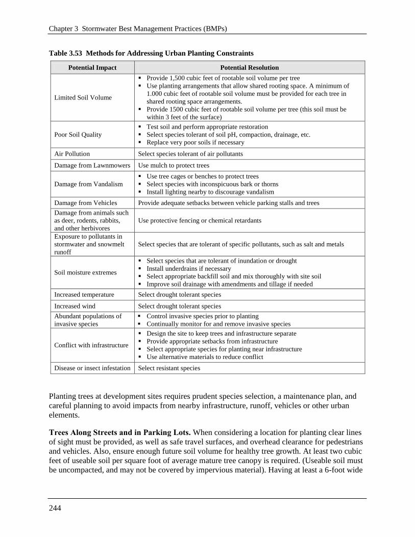
Chapter 3 Stormwater Best Management Practices (BMPs)
244
Table 3.53 Methods for Addressing Urban Planting Constraints
Potential Impact Potential Resolution
Limited Soil Volume
Provide 1,500 cubic feet of rootable soil volume per tree
Use planting arrangements that allow shared rooting space. A minimum of
1.000 cubic feet of rootable soil volume must be provided for each tree in
shared rooting space arrangements.
Provide 1500 cubic feet of rootable soil volume per tree (this soil must be
within 3 feet of the surface)
Poor Soil Quality
Test soil and perform appropriate restoration
Select species tolerant of soil pH, compaction, drainage, etc.
Replace very poor soils if necessary
Air Pollution Select species tolerant of air pollutants
Damage from Lawnmowers Use mulch to protect trees
Damage from Vandalism
Use tree cages or benches to protect trees
Select species with inconspicuous bark or thorns
Install lighting nearby to discourage vandalism
Damage from Vehicles Provide adequate setbacks between vehicle parking stalls and trees
Damage from animals such
as deer, rodents, rabbits,
and other herbivores
Use protective fencing or chemical retardants
Exposure to pollutants in
stormwater and snowmelt
runoff
Select species that are tolerant of specific pollutants, such as salt and metals
Soil moisture extremes
Select species that are tolerant of inundation or drought
Install underdrains if necessary
Select appropriate backfill soil and mix thoroughly with site soil
Improve soil drainage with amendments and tillage if needed
Increased temperature Select drought tolerant species
Increased wind Select drought tolerant species
Abundant populations of
invasive species
Control invasive species prior to planting
Continually monitor for and remove invasive species
Conflict with infrastructure
Design the site to keep trees and infrastructure separate
Provide appropriate setbacks from infrastructure
Select appropriate species for planting near infrastructure
Use alternative materials to reduce conflict
Disease or insect infestation Select resistant species
Planting trees at development sites requires prudent species selection, a maintenance plan, and
careful planning to avoid impacts from nearby infrastructure, runoff, vehicles or other urban
elements.
Trees Along Streets and in Parking Lots. When considering a location for planting clear lines
of sight must be provided, as well as safe travel surfaces, and overhead clearance for pedestrians
and vehicles. Also, ensure enough future soil volume for healthy tree growth. At least two cubic
feet of useable soil per square foot of average mature tree canopy is required. (Useable soil must
be uncompacted, and may not be covered by impervious material). Having at least a 6-foot wide

3.14 Tree Planting and Preservation
245
planting strip or locating sidewalks between the trees and street allows more rooting space for
trees in adjacent property.
Select tree species that are drought tolerant, can grow in poor or compacted soils, and are tolerant
to typical urban pollutants (oil and grease, metals, and chlorides). Additionally, select species
that do not produce excessive fruits, nuts, or leaf litter, that have fall color, spring flowers or
some other aesthetic benefit, and can be limbed up to 6 feet to provide pedestrian and vehicle
traffic underneath. The District Department of Transportation, Urban Forestry Administration
(DDOT UFA) provides guidance on preferred street tree species based on neighborhoods.
Planting Techniques. Prepare a hole no deeper than the root ball or mass but two to three times
wider than the spread of the root ball or mass. The majority of the roots on a newly planted tree
will develop in the top 12 inches of soil and spread out laterally. There are some additional
considerations depending on the type of plant material being used (Table 3.54).
Table 3.54 Tree Planting Techniques
Plant Material Planting Technique Planting Season
Container grown Hand plant or use mechanical planting tools (e.g., auger) Spring or fall,
summer if irrigated
Balled and burlapped Use backhoe (or other specialized equipment) or hand plant Spring or fall
Sources: Palone and Todd (1998), WSAHGP (2002)
One of the most important planting guidelines is too make sure the tree is not planted too deeply.
The root collar, the lowest few inches of trunk just above its junction with the roots (often
indicated by a flare), should be exposed (Flott, 2004). Trees planted too deeply have buried root
collars, and are weakened, stressed, and predisposed to pests and disease (Flott, 2004). Trees
planted too deeply can also form adventitious roots near the soil surface in an attempt to
compensate for the lack of oxygen available to buried roots. Adventitious roots are not usually
large enough to provide support for a large tree and may eventually lead to collapse (Flott, 2004).
ISA (2005) provides additional guidance on how to avoid planting too deeply. It is generally
better to plant the tree a little high, that is, with the base of the trunk flare 2 to 3 inches above the
soil, rather than at or below the original growing level (ISA, 2003b).
Proper handling during planting is essential to avoid prolonged transplant shock and ensure a
healthy future for new trees and shrubs. Trees should always be handled by the root ball or
container, never by the trunk. Specifications for planting a tree are illustrated in Figure 3.42.
Trees must be watered well after planting.

Chapter 3 Stormwater Best Management Practices (BMPs)
246
Figure 3.42 Tree planting guidelines. (Adapted from Flott, 2004 and ISA, 2003b).
Steep slopes require additional measures to ensure planting success and reduce erosion,
especially if the slope receives stormwater runoff from upland land uses. Depending on the
steepness of the slope and the runoff volume, rill or gully erosion may occur on these slopes,
requiring a twofold approach: controlling the stormwater and stabilizing the slope.
Erosion control blankets are recommended to temporarily stabilize soil on slopes until vegetation
is established (Caraco, 2000; Morrow and others, 2002). Erosion control fabrics come in a
variety of weights and types, and should be combined with vegetation establishment such as
seeding. Other options for stabilizing slopes include applying compost or bark mulch, plastic
sheeting, or sodding (Caraco, 2000).
Trees will add stability to slopes because of their deep roots, provided they are not planted by
digging rows of pits across a slope (Morrow and others, 2002). Required maintenance will
include mowing (if slopes are not too steep), and establishing cover on bare or eroded areas.

3.14 Tree Planting and Preservation
247
Planting methods for slopes steeper than 3:1 (1 foot vertical change for every 3 horizontal feet)
involve creating a level planting space on the slope (see Figure 3.43). A terrace can be dug into
the slope in the shape of a step. The existing slope can be cut and the excavated soil can be used
as fill. A low soil berm (or rock berm) can be formed at the front edge of each step or terrace to
slow the flow of water. Trees can also be planted in clusters on slopes (using the above method)
to limit potential for desiccation. Staggering tree placement and mulching will prevent water
from running straight downhill.
Figure 3.43 The specifications for planting on a steep slope, require creating a level planting
surface.
Post-Planting Tree Protection. Once the tree has been properly planted, 2 to 4 inches of
organic mulch must be spread over the soil surface out to the drip line of the tree. If planting a
cluster of trees, mulch the entire planting area. Slow-decomposing organic mulches, such as
shredded bark, compost, leaf mulch, or wood chips provide many added benefits for trees. Mulch
that contains a combination of chips, leaves, bark, and twigs is ideal for reforestation sites.
(ACB, 2000; ISA, 2003a). Grass clippings and sawdust are not recommended as mulches
because they decompose rapidly and require frequent application, resulting in reduced benefits.
For well-drained sites up to 4 inches of mulch may be applied, and for poorly drained sites a
thinner layer of mulch should be applied. Mulch should never be more than 4 inches deep or
applied right next to the tree trunk; however, a common sight in many landscaped areas is the
―mulch volcano‖. This over-mulching technique can cause oxygen and moisture-level problems,
and decay of the living bark at the base of the tree. A mulch-free area, 2- to 3-inches wide at the
base of the tree, must be provided to avoid moist bark conditions and prevent decay (ISA,
2003a).

Chapter 3 Stormwater Best Management Practices (BMPs)
248
Studies have shown that trees will establish more quickly and develop stronger trunk and root
systems if they are not staked at the time of planting (ISA, 2003b). Staking for support may be
necessary only for top-heavy trees or at sites where vandalism or windy exposure are a concern
(Buckstrup and Bassuk, 2003; Doherty and others, 2003; ISA, 2003b).
If staking is necessary for support, two stakes used in conjunction with a wide flexible tie
material will hold the tree upright, provide flexibility, and minimize injury to the trunk. To
prevent damage to the root ball, stakes should be placed in undisturbed soil beyond the outer
edges of the root ball. Perhaps the most important part of staking is its removal. Over time, guy
wires (or other tie material) can cut into the growing trunk bark and interfere with the movement
of water and nutrients within the tree. Staking material should be removed within 1 year of
planting (Doherty and others, 2003).
3.14.3 Tree Inspection Criteria
An initial inspection by a qualified professional must be done to ensure the tree has been planted,
watered, and protected correctly with locations flagged if appropriate. For newly planted trees,
transplant shock is common and causes stress on a new tree. For this reason, newly planted trees
must be inspected more frequently than established trees. The time it takes for a tree to become
established varies with the size at planting, species, stock, and site conditions, but generally,
trees should be inspected every few months during the first 3 years after planting, to identify
problems and implement repairs or modify maintenance strategies (WSAHGP, 2002).
After the first 3 years, annual inspections are sufficient to check for problems. Trees must also be
inspected after major storm events for any damage that may have occurred. The inspection
should take only a few minutes per tree, but prompt action on any problems encountered results
in healthier, stronger trees. Inspections should include an assessment of overall tree health, an
assessment of survival rate of the species planted, cause of mortality, if maintenance is required,
insect or disease problems, tree protection adjustment, and weed control condition.
DDOE’s construction phase inspection checklist for tree planting and preservation can be found
in Appendix K.
3.14.4 Tree Maintenance Criteria
Water newly planted trees regularly (at least once a week) during the first growing season. Water
trees less frequently (about once a month) during the next two growing seasons. After three
growing seasons, water trees only during drought. The exact watering frequency will vary for
each tree and site.
A general horticultural rule of thumb is that trees need 1 inch of rainfall per week during the
growing season (Petit and others, 1995). This means new trees need a minimum of 25 gallons of
water a week to stay alive (http://caseytrees.org/get-involved/water/). Water trees deeply and
slowly near the roots. Light, frequent watering of the entire plant can actually encourage roots to
grow at the surface. Soaker hoses and drip irrigation work best for deep watering of trees. It is
recommend that slow leak watering bags or tree buckets are installed to make watering easier
and more effective. Continue watering until mid-fall, tapering off during lower temperatures.

3.14 Tree Planting and Preservation
249
Pruning is usually not needed for newly planted trees but may be beneficial for tree structure. If
necessary, prune only dead, diseased, broken or crossing branches at planting (Doherty and
others, 2003; Trowbridge and Bassuk, 2004). As the tree grows, lower branches may be pruned
to provide clearance above the ground, or to remove dead or damaged limbs.
DDOE’s maintenance inspection checklist for tree planting and preservation and the
Maintenance Service Completion Inspection form can be found in Appendix L.
Declaration of Covenants. A maintenance covenant is required for all stormwater management
practices. The covenant specifies the property owner’s primary maintenance responsibilities, and
authorizes DDOE staff to access the property for inspection or corrective action in the event the
proper maintenance is not performed. The covenant is attached to the deed of the property (see
standard form, variations exist for scenarios where stormwater crosses property lines). A
template form is provided at the end of Chapter 5 (see Figure 5.4), although variations will exist
for scenarios where stormwater crosses property lines. The covenant is between the property and
the Government of the District of Columbia. It is submitted through the Office of the Attorney
General. All SWMPs have a maintenance agreement stamp that must be signed for a building
permit to proceed. There may be a maintenance schedule on the drawings themselves or the
plans may refer to the maintenance schedule (Exhibit C in the covenant).
Covenants are not required on government properties, but maintenance responsibilities must be
defined through a partnership agreement or a memorandum of understanding.
Waste Material. Waste material from the repair, maintenance, or removal of a BMP or land
cover shall be removed and disposed of in compliance with applicable federal and District law.
3.14.5 Tree Stormwater Compliance Calculations
Trees receive retention value but they are not accepted total suspended solids (TSS) treatment
practices.
To ensure appropriate stormwater benefits associated with proposed tree preservation or
planting, all trees receiving retention value must be properly maintained until redevelopment of
the area occurs. If trees die they must be replaced with a similar tree no longer than 6 months
from time of death in an appropriate location.
Preserved trees that meet the requirements described above receive a retention value of 20 cubic
feet each. Planted trees that meet the requirements described above receive a retention value of
10 cubic feet each.
Note: Trees planted as part of another BMP, such as a bioretention area, also receive the 10 cubic
foot retention value. Retention values are shown in Tables 3.55 and 3.56 below.
Table 3.55 Preserved Tree Retention Value and Pollutant Removal
Retention Value = 20cf (150 gallons)
Accepted TSS Treatment Practice No
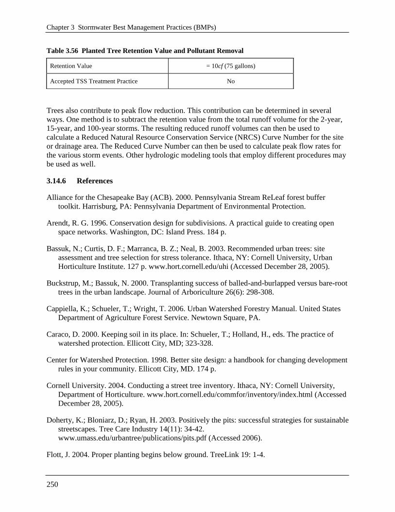
Chapter 3 Stormwater Best Management Practices (BMPs)
250
Table 3.56 Planted Tree Retention Value and Pollutant Removal
Trees also contribute to peak flow reduction. This contribution can be determined in several
ways. One method is to subtract the retention value from the total runoff volume for the 2-year,
15-year, and 100-year storms. The resulting reduced runoff volumes can then be used to
calculate a Reduced Natural Resource Conservation Service (NRCS) Curve Number for the site
or drainage area. The Reduced Curve Number can then be used to calculate peak flow rates for
the various storm events. Other hydrologic modeling tools that employ different procedures may
be used as well.
3.14.6 References
Alliance for the Chesapeake Bay (ACB). 2000. Pennsylvania Stream ReLeaf forest buffer
toolkit. Harrisburg, PA: Pennsylvania Department of Environmental Protection.
Arendt, R. G. 1996. Conservation design for subdivisions. A practical guide to creating open
space networks. Washington, DC: Island Press. 184 p.
Bassuk, N.; Curtis, D. F.; Marranca, B. Z.; Neal, B. 2003. Recommended urban trees: site
assessment and tree selection for stress tolerance. Ithaca, NY: Cornell University, Urban
Horticulture Institute. 127 p. www.hort.cornell.edu/uhi (Accessed December 28, 2005).
Buckstrup, M.; Bassuk, N. 2000. Transplanting success of balled-and-burlapped versus bare-root
trees in the urban landscape. Journal of Arboriculture 26(6): 298-308.
Cappiella, K.; Schueler, T.; Wright, T. 2006. Urban Watershed Forestry Manual. United States
Department of Agriculture Forest Service. Newtown Square, PA.
Caraco, D. 2000. Keeping soil in its place. In: Schueler, T.; Holland, H., eds. The practice of
watershed protection. Ellicott City, MD; 323-328.
Center for Watershed Protection. 1998. Better site design: a handbook for changing development
rules in your community. Ellicott City, MD. 174 p.
Cornell University. 2004. Conducting a street tree inventory. Ithaca, NY: Cornell University,
Department of Horticulture. www.hort.cornell.edu/commfor/inventory/index.html (Accessed
December 28, 2005).
Doherty, K.; Bloniarz, D.; Ryan, H. 2003. Positively the pits: successful strategies for sustainable
streetscapes. Tree Care Industry 14(11): 34-42.
www.umass.edu/urbantree/publications/pits.pdf (Accessed 2006).
Flott, J. 2004. Proper planting begins below ground. TreeLink 19: 1-4.
Retention Value = 10cf (75 gallons)
Accepted TSS Treatment Practice No

3.14 Tree Planting and Preservation
251
Georgia Forestry Commission (GFC). 2002. Community tree planting and establishment
guidelines. Dry Branch, GA.
Gilman, E. F. 1997. Trees for urban and suburban landscapes. Albany, NY: Delmar Publishers.
Greenfeld, J.; Herson, L.; Karouna, N.; Bernstein, G. 1991. Forest conservation manual:
guidance for the conservation of Maryland’s forests during land use changes, under the 1991
Forest Conservation Act. Washington, DC: Metropolitan Washington Council of
Governments. 122 p.
Hairston-Strang, A. 2005. Riparian forest buffer design and maintenance. Annapolis: Maryland
Department of Natural Resources.
http://www.dnr.state.md.us/forests/download/rfb_design&maintenance.pdf
Head, C.; Robinson, F.; O’Brien, M. 2001. Best management practices for community trees: a
guide to tree conservation in Athens-Clarke County, Georgia. Athens, GA: Athens-Clarke
County Unified Government.
International Society of Arboriculture (ISA). 2005. Avoiding excessive soil over the root systems
of trees. Arborist News, April.
International Society of Arboriculture (ISA). 2003a. Proper mulching techniques. Champaign,
IL: International Society of Arboriculture. www.treesaregood.com/treecare/mulching.aspx
(Accessed 2006).
International Society of Arboriculture (ISA). 2003b. New tree planting. Champaign, IL:
International Society of Arboriculture. www.treesaregood.com/treecare/tree_planting.aspx
(Accessed 2006).
Johnson, G. R. 2005. Protecting trees from construction damage: a homeowner’s guide. St. Paul,
MN: Regents of the University of Minnesota.
www.extension.umn.edu/distribution/housingandclothing/DK6135.html (Accessed
December 28, 2005).
Kochanoff, S., 2002. Trees vs. power lines: priorities and implications in Nova Scotia. Presented
at the 5th Annual Canadian Urban Forest Conference. Markham, ON.
Maryland National Capital Parks and Planning Commission. 1992. Trees. Approved Technical
Manual. Maryland National Capital Parks and Planning Commission, Montgomery County,
MD. 144 p. http://www.montgomeryplanning.org/environment/forest/trees/toc_trees.shtm
Meyer, D. 1993. Tree shelters for seedling protection and increased growth. Forestry Facts 59.
Madison, WI: University of Wisconsin Extension.
Minnesota Department of Natural Resources. 2000. Conserving wooded areas in developing
communities. BMPs in Minnesota. Minnesota Department of Natural Resources, St. Paul,
MN. 113 p. www.dnr.state.mn.us/forestry/urban/bmps.html (Accessed December 28, 2005).

Chapter 3 Stormwater Best Management Practices (BMPs)
252
Morrow, S.; Smolen, M.; Stiegler, J.; Cole, J. 2002. Using vegetation for erosion control.
Landscape Architect 18(11): 54-57.
Nebraska Forest Service. 2004. Tree selection and placement. Storm Damage Bulletin No. 7.
http://digitalcommons.unl.edu/cgi/viewcontent.cgi?article=1068&context=nebforestpubs
Palone, R. S.; Todd, A. H., eds. 1998. Chesapeake Bay riparian handbook: a guide for
establishing and maintaining riparian forest buffers. NA-TP-02-97. Radnor, PA: USDA
Forest Service, Northeastern Area State and Private Forestry.
Pennsylvania State University. 1999. A guide to preserving trees in development projects.
University Park, PA: Penn State College of Agricultural Sciences, Cooperative Extension. 27
p.
Pennsylvania State University (PSU). 1997. Questions about trees and utilities. Forestry Fact
Sheet #7. University Park: Pennsylvania State University, College of Agricultural Sciences.
Petit, J.; Bassert, D. L.; Kollin, C. 1995. Building greener neighborhoods. Trees as part of the
plan. Washington, DC: American Forests and the National Association of Homebuilders.
Schueler, T. R. 1995. Site planning for urban stream protection. Ellicott City, MD: Center for
Watershed Protection. 232 p.
Schueler, T.; Brown, K. 2004. Urban stream repair practices. Version 1.0. Manual 4 of the Urban
Subwatershed Restoration Manual Series. Ellicott City, MD: Center for Watershed
Protection.
Sweeney, B. W. 1993. Effects of streamside vegetation on macroinvertebrate communities of
White Clay Creek in Eastern North America. In: Proceedings of the Academy of Natural
Sciences of Philadelphia. Philadelphia, PA; 291-340.
Tree Care Industry Association (TCIA). 2004. ANSI A300 Standards for tree care operations.
Manchester, NH; www.natlarb.com/content/laws/a-300.htm (Accessed 2005).
Trowbridge, P.; Bassuk, N. 2004. Trees in the urban landscape: site assessment, design, and
installation. Hoboken, NJ: John Wiley & Sons, Inc.
USDA Forest Service. 1998. Volunteer training manual. Amherst, MA: Northeast Center for
Urban and Community Forestry. 86 p. www.umass.edu/urbantree/volmanual.pdf (Accessed
December 28, 2005).
Washington State Aquatic Habitat Guidelines Program (WSAHGP). 2002. Integrated
streambank protection guidelines. Olympia, WA. Unpaginated.

253
Chapter 4 Selecting and Locating the Most
Effective Stormwater Best
Management Practice System
4.1 Choosing Stormwater Management Best Practices (BMPs)
This chapter outlines a general process for selecting appropriate BMPs at a development site.
Guidelines are presented for choosing which BMPs can meet the retention and treatment volume
targets for design storms and which BMPs are most feasible when various site constraints are
present.
This chapter represents guidelines, not rules, to determine the most appropriate BMP for a site. It
is important to note that certain BMP design modifications or specific site characteristics may
allow for a particular BMP to become better suited at a particular location. Several of these
design modifications are noted in the following tables and are described in more detail in the
individual BMP specifications (see Chapter 3).
The following questions organize a framework for decision making:
Regulatory Criteria
Can the BMP meet all stormwater sizing criteria at the site or are a combination of BMPs
needed?
Land Use Factors
Which practices are best suited for the proposed land use at this site?
Physical Feasibility Factors
Are there any physical constraints at the project site that may restrict or preclude the use of
a particular BMP?
Community and Environmental Factors
Do the remaining BMPs have any important community or environmental benefits or
drawbacks that might influence the selection process?
Location and Permitting Considerations
What environmental features must be avoided or considered when locating the BMP system
at a site to fully comply with District and federal regulations?

Chapter 4 Selecting and Locating the Most Effective Stormwater Best Management Practice System
254
4.2 Regulatory Compliance
Table 4.1 summarizes the capability of each BMP to meet the stormwater management sizing
criteria outlined in Chapter 2. Designers can use Table 4.1 to screen BMP options to determine
whether a particular BMP can meet the SWRv storage, peak discharge (Qp2, Qp15, and Qf), and
pollutant removal requirements. Finding that a particular BMP cannot meet a requirement does
not necessarily mean that it should be eliminated from consideration. This screening process can
reduce BMP options to a manageable number and determine whether a single BMP or a group of
BMPs will be needed to meet stormwater sizing criteria at the site.
The following are key considerations for compliance:
Stormwater Retention Volume (SWRv) Storage. A single BMP may not be capable of
meeting the SWRv requirement. This column can assist in identifying supplemental
practices.
Quantity Control (Qp2, Qp15, or Qf). These columns show whether a BMP can typically
meet the peak discharge requirements.
Pollutant Removal. This column examines the capability of each BMP option to remove
total suspended solids (TSS) from stormwater runoff.
Note: Table 4.1 should be used as a guide for how practices typically perform. Individual designs
may be sized or designed with greater or lesser capabilities than are indicated in the table.
Table 4.1 BMP Selection Based on Regulatory Criteria
Code BMP SWRv
Storage
Qp2/Qp15
Control
Qf
Control
TSS
Removal
G-1 Extensive Green Roof
N/A
G-2 Intensive Green Roof
R-1 Rainwater Harvesting N/A
D-1 Simple Disconnection to a Pervious Area
NO D-2 Simple Disconnection to a Conservation Area
D-3 Simple Disconnection to a Soil Compost
Amended Filter Path
P-1 Porous Asphalt
N/A or
Yes* P-2 Pervious Concrete
P-3 Permeable Pavers
B-1 Traditional Bioretention
N/A or
Yes*
B-2 Streetscape Bioretention
B-3 Expanded Tree Pits
B-4 Stormwater Planters
B-5 Residential Rain Gardens
F-1 Surface Sand Filter
Yes F-2 1-Chamber Underground Sand Filter
F-3 3-Chamber Underground Sand Filter

Chapter 4 Selecting and Locating the Most Effective Stormwater Best Management Practice System
255
Code BMP SWRv
Storage
Qp2/Qp15
Control
Qf
Control
TSS
Removal
F-4 Perimeter Sand Filter
I-1 Infiltration Trench N/A
I-2 Infiltration Basin
O-1 Grass Channels
No O-2 Dry Swale Yes O-3 Wet Swale Yes
P-1 Micropool Extended Detention Pond
Yes P-2 Wet Pond
P-3 Wet Extended Detention Pond
W-1 Shallow Wetland Yes
W-2 Extended Detention Shallow Wetland
S-1 Underground Detention No
S-2 Dry Extended Detention Pond
PP-1 Proprietary Practice Yes
TP-1 Tree Preservation No
TP-2 Tree Planting
= Yes; = Partial; = Minor or No Benefit
* Depends upon design type.
4.3 Land Use Factors
Designers can use Table 4.2 to evaluate BMPs that are best suited to a particular land use,
including highly urbanized areas.
The following are key considerations for land use factors:
Residential. This column identifies the best treatment options in medium to high density
residential developments.
Commercial Development. This column identifies practices that are suitable for new
commercial development.
Roads and Highways. This column identifies the best practices to treat runoff from major
roadway and highway systems.
Hotspot Land Uses. This column examines the capability of BMPs to treat runoff from
designated hotspots. BMPs that receive hotspot runoff may have design restrictions, as noted.

Chapter 4 Selecting and Locating the Most Effective Stormwater Best Management Practice System
256
Table 4.2 BMP Selection Based on Land Use Screening Factors
Code BMP Residential Commercial Roads and
Highways Hotspots
G-1 Extensive Green Roof
G-2 Intensive Green Roof
R-1 Rainwater Harvesting
D-1 Simple Disconnection to a Pervious Area
D-2 Simple Disconnection to a Conservation Area
D-3 Simple Disconnection to a Soil Compost
Amended Filter Path
P-1 Porous Asphalt
P-2 Pervious Concrete
P-3 Permeable Pavers
B-1 Traditional Bioretention
B-2 Streetscape Bioretention
B-3 Expanded Tree Pits
B-4 Stormwater Planters
B-5 Residential Rain Gardens
F-1 Surface Sand Filter
F-2 1-Chamber Underground Sand Filter
F-3 3-Chamber Underground Sand Filter
F-4 Perimeter Sand Filter
I-1 Infiltration Trench
I-2 Infiltration Basin
O-1 Grass Channel
O-2 Dry Swale
O-3 Wet Swale
P-1 Micropool Extended Detention Pond
P-2 Wet Pond
P-3 Wet Extended Detention Pond
W-1 Shallow Wetland
W-2 Extended Detention Shallow Wetland
S-1 Underground Detention
S-2 Dry Pond
PP-1 Proprietary Practice
TP-1 Tree Preservation
TP-2 Tree Planting
= Yes; = Maybe; = No
- Recommended for low volume roads or parking lanes
-Yes, only if designed with an impermeable liner
-May require pond liner to reduce the risk of GW contamination

Chapter 4 Selecting and Locating the Most Effective Stormwater Best Management Practice System
257
4.4 Physical Feasibility Factors
Typically, the designer narrows the BMP selection list based on regulatory goals and land use
constraints before considering physical feasibility factors. Table 4.3 identifies the typical
physical conditions needed for each type of BMP. Designers can use Table 4.3 to screen BMP
options to determine whether the soils, water table, drainage area, slope, or head conditions
present at a particular development site might limit the use of a BMP. These factors are intended
as guidelines rather than requirements.
The following are key considerations for physical feasibility:
Underlying Soils. The designer should use NRCS hydrologic soils maps to generally
identify expected soils and their locations at the site. More detailed geotechnical tests are
required during BMP design to evaluate infiltration feasibility and related design parameters.
Once the infiltration rate at a site has been measured, use this column and Table 4.4 to
identify recommended design criteria for proposed BMPs that have an infiltration option.
Distance to Water Table. Measure the depth of the groundwater and estimate the depth of
the seasonally high water table (see Appendix O). Use this column as an aid to determine
recommended BMP sizing.
Contributing Drainage Area. Delineate the contributing drainage area to the proposed
BMP, and use this column as an aid to determine the appropriate sizing factor. If the drainage
area present at a site is slightly greater than the maximum allowable drainage area for a
practice, some leeway is permitted. Likewise, the minimum drainage areas indicated for
ponds and wetlands should not be considered inflexible limits, and may be increased or
decreased depending on water availability (baseflow or groundwater) or the mechanisms
employed to prevent clogging or ensure an impermeable pond bottom.
Practice Surface Slope. Evaluate the site topography. Determine the potential for cut and fill
operations. Use this column as an aid to evaluate BMP surface slope restrictions.
Specifically, the slope restrictions refer to how flat the area where the practice is installed
must be.
Head. To evaluate BMP options, determine the elevation of the discharge point, and use this
column as an aid to estimate the elevation difference needed from the inflow to the outflow
to allow for gravity operation.

Chapter 4 Selecting and Locating the Most Effective Stormwater Best Management Practice System
258
Table 4.3 BMP Selection Based on Physical Feasibility Screening Factors
Code BMP List Underlying
Soils
Distance to
Water
Table
(ft)
Contributing
Drainage
Area
(ac)
Practice
Surface
Slope
(%)
Head
(ft)
G-1 Extensive Green Roof N/A N/A
green roof
surface area +
25%
1–2a N/A
G-2 Intensive Green Roof
R-1 Rainwater Harvesting N/A N/A no limit N/A N/A
D-1 Simple Disconnection to a
Pervious Area
all soils
N/A
< 1,000 ft2 per
rooftop
downspoutb
< 5
N/A D-2 Simple disconnection to a
conservation area < 6
D-3 Simple Disconnection to a Soil
Compost Amended Filter Path < 5
P-1 Porous Asphalt all soils
(i < 0.5 in./hr
may require
underdrains)
2 2–5 × practice
surface area < 5 2–4 P-2 Pervious Concrete
P-3 Permeable Pavers
B-1 Traditional Bioretention all soils
(i < 0.5 in./hr
may require
underdrains)
2
< 2.5
< 1 4–5
B-2 Streetscape Bioretention < 1
B-3 Expanded Tree Pits < 1
B-4 Stormwater Planters < 1
B-5 Residential Rain Gardens < 1
F-1 Surface Sand Filter
all soils 2
< 5
N/A
5
F-2 1-Chamber Underground Sand
Filter < 10,000 ft
2 5–10
F-3 3-Chamber Underground Sand
Filter < 2 5–10
F-4 Perimeter Sand Filter < 2 2–3
I-1 Infiltration Trench i > 0.5 in/hr is
preferred 2
< 2 < 1 2
I-2 Infiltration Basin < 5
O-1 Grass Channel all soils 2
< 2.5 < 4
1
O-2 Dry Swale
all soils
(i < 0.5 in./hr
may require
underdrains)
2 3–5
O-3 Wet Swale i < 0.5 in./hr intersect WT 1
P-1 Micropool Extended Detention
Pond soils i > 0.5
in./hr may
require pond
liner
N/A 10–25
< 1
6–8
P-2 Wet Pond N/A 10–25 6–8
P-3 Wet Extended Detention Pond N/A 10–25 6–8
W-1 Shallow Wetland soils i > 0.5
in./hr may
require pond
liner
N/A
> 25e < 1 2–4
W-2 Extended Detention Shallow
Wetland N/A
S-1 Underground Detention all soils
no
restrictions no restrictions < 1 > 5
S-2 Dry Extended Detention Pond 2 > 10d < 1 6–8

Chapter 4 Selecting and Locating the Most Effective Stormwater Best Management Practice System
259
Code BMP List Underlying
Soils
Distance to
Water
Table
(ft)
Contributing
Drainage
Area
(ac)
Practice
Surface
Slope
(%)
Head
(ft)
PP-1 Proprietary Practice All soils 2 design
dependent N/A 2–5
TP-1 Tree Preservation All soils
N/A N/A N/A N/A
TP-2 Tree Planting N/A N/A
Notes: i= infiltration rate or permeability, WT= water table, N/A= not applicable
a Green roof slope can be up to 25% if baffles are used to ensure detention of the design storm
b For impervious areas other than rooftop, the longest contributing impervious area flow path cannot exceed 75
feet.
c The required head for bioretention areas can be reduced in small applications or when an upturned or elevated
underdrain design is used
d No limit but practical drainage area limitations may exist due to minimum orifice size (e.g., 1-inch diameter with
internal orifice)
e CDA can be smaller if the practice intersects the water table
Table 4.4 Selection of Infiltration BMPs Based on Measured Infiltration Rate*
Measured Infiltration Rate (in./hr)
Less than 0.25 0.25 to 0.5 More than 0.5
Recommended
Design
Solution
Use Bioretention, Dry
Swale, or Permeable
Pavement (likely with an
underdrain).
Do not use Infiltration
Trench/Basin.
Use Bioretention, Dry Swale, or
Permeable Pavement (likely with an
underdrain). It may be beneficial to
include an infiltration sump below the
underdrain invert.
Infiltration Trench/Basin may not be
appropriate.
Use Infiltration
Trench/Basin,
Bioretention, Dry
Swale, or Permeable
Pavement without an
underdrain.
*Designers must use ½ of the measured infiltration rate for design purposes, as indicated in the design equations
given in Chapter 3.
4.5 Community and Environmental Factors
Designers can use Table 4.5 to compare the BMP options with regard to maintenance, habitat,
community acceptance, cost, safety, space consumption, and other environmental factors. Table
4.5 employs a comparative index approach to rank the benefits of community and environmental
factors as high, medium, or low.
The following are key considerations for community and environmental factors:
Maintenance Burden. This column identifies the relative maintenance effort needed for
each BMP option, in terms of the frequency of scheduled maintenance, chronic maintenance
problems (such as clogging), and reported failure rates. All BMPs require routine inspection
and maintenance (see Appendix L Maintenance Inspection Checklists).

Chapter 4 Selecting and Locating the Most Effective Stormwater Best Management Practice System
260
Cost. This column ranks BMPs according to their relative construction cost per cubic foot of
stormwater retained, as determined from cost surveys and local experience.
Safety Risk. This column provides a comparative index of the potential safety risks of each
BMP option, when designed according to the performance criteria outlined in Chapter 3. The
index is included to highlight the need for considerations of liability and public safety in
locations, such as residential, public space, schools, and others. A comparatively higher risk
BMP may require signage, fencing, or other measures needed to alert the general public or
maintenance provider of a potentially harmful situation.
Space Required. This column provides a comparative index of the amount of space each
BMP option typically consumes at a site. It may be helpful to consider this factor at an early
stage of design because many urban BMPs are constrained by availability of open land.
Environmental Factors. This column assesses the range of environmental factors
considered under the Green Area Ratio (GAR) process to identify the broader human and
environmental beneficial intersections some BMPs provide. For instance some BMPs
contribute to air quality improvements and reduce the urban heat island effect.
Habitat Value. This column evaluates the ability of BMPs to provide wildlife or wetland
habitat, assuming that an effort is made to landscape them appropriately. Objective criteria
include size, water features, wetland features, and vegetative cover of the BMP and its buffer.
Other Factors. This column indicates other considerations in BMP selection.

Chapter 4 Selecting and Locating the Most Effective Stormwater Best Management Practice System
261
Table 4.5 BMP Selection Based on Community and Environmental Factors
Oth
er F
act
ors
Incr
ease
s st
ruct
ura
l
lo
adin
g o
n b
uil
din
g
Can
be
use
d a
s
lan
dsc
apin
g f
eatu
res
Min
imiz
e co
ncr
ete
Ou
t o
f si
gh
t
Ou
t o
f si
gh
t
Tra
ffic
bea
rin
g
Av
oid
lar
ge
sto
ne
Fre
qu
ent
po
oli
ng
No
tes:
H =
Hig
h;
M =
Med
ium
; L
=L
ow
* C
ost
bas
ed o
n $
per
cu
bic
foo
t o
f st
orm
wat
er t
reat
ed
Ha
bit
at
Va
lue
L
M
L
L
L
M
M
M
L
M
L
L
En
vir
on
men
tal
Ben
efit
s
H
H
M
M
H
L
L
Sp
ace
Req
uir
ed
L
L
M
L
M
M
L
L
L
M
L
L
M
M
Sa
fety
Ris
k
L
L
L
L
L
L
M
M
L
L
Co
st*
H
H
M
L
H
L
H
H
M
L
L
M
H
M
M
Ma
inte
na
nce
Bu
rden
L
M
L
L
H
M
H
M
L
L
M
H
H
M
L
BM
P L
ist
Ex
ten
siv
e G
reen
Ro
of
In
ten
siv
e G
reen
Ro
of
Rai
nw
ater
Har
ves
tin
g
Sim
ple
Dis
con
nec
tio
n t
o a
Per
vio
us
Are
a
Sim
ple
Dis
con
nec
tio
n t
o a
Con
serv
atio
n
Are
a
Sim
ple
Dis
con
nec
tio
n t
o a
Soil
Co
mp
ost
Am
end
ed F
ilte
r P
ath
Po
rou
s A
sph
alt
Per
vio
us
Co
ncr
ete
Per
mea
ble
Pav
ers
Tra
dit
ion
al B
iore
ten
tio
n
Str
eets
cap
e B
iore
ten
tio
n
Ex
pan
ded
Tre
e P
its
Sto
rmw
ater
Pla
nte
rs
Res
iden
tial
Rai
n G
ard
ens
Su
rfac
e S
and
Fil
ter
1-C
ham
ber
Und
ergro
un
d S
and
Fil
ter
3-C
ham
ber
Und
ergro
un
d S
and
Fil
ter
Per
imet
er S
and
Fil
ter
Infi
ltra
tio
n T
ren
ch
Infi
ltra
tio
n B
asin
Co
de
G-1
G-2
R-1
D-1
D-2
D-3
P-1
P-2
P-3
B-1
B-2
B-3
B-4
B-5
F-1
F-2
F-3
F-4
I-1
I-2

Chapter 4 Selecting and Locating the Most Effective Stormwater Best Management Practice System
262
Oth
er F
act
ors
O
ut
of
sig
ht
T
rash
/deb
ris
H
igh
pon
d p
rem
ium
L
imit
ED
dep
th
Po
ssib
le m
osq
uit
oes
No
tes:
H =
Hig
h;
M =
Med
ium
; L
=L
ow
* C
ost
bas
ed o
n $
per
cu
bic
foo
t o
f st
orm
wat
er t
reat
ed
Ha
bit
at
Va
lue
L
L
H
H
H
L
L
M
En
vir
on
men
tal
Ben
efit
s
L
M
M
H
M
Sp
ace
Req
uir
ed
L
H
H
H
M
Sa
fety
Ris
k
M
M
L
M
L
Co
st*
H
L
L
M
L
M
M
Ma
inte
na
nce
Bu
rden
M
M
H
H
M
M
H
H
BM
P L
ist
Un
der
gro
und
Det
enti
on
Dry
Po
nd
Mic
rop
oo
l E
xte
nd
ed D
eten
tion
Po
nd
Wet
Po
nd
Wet
Ex
ten
ded
Det
enti
on
Pond
Sh
allo
w W
etla
nd
Ex
ten
ded
Det
enti
on
Sh
allo
w W
etla
nd
Gra
ss C
han
nel
Dry
Sw
ale
Wet
Sw
ale
Co
de
S-1
S-2
P-1
P-2
P-3
W-1
W-2
O-1
O-2
O-3

Chapter 4 Selecting and Locating the Most Effective Stormwater Best Management Practice System
263
4.6 Location and Permitting Considerations
In this step, the designer follows an environmental features checklist that asks whether any of the
following are present at the site: wetlands, waters of the United States, floodplains, and
development infrastructure. Brief guidance is then provided on how to locate BMPs to avoid
impacts to sensitive resources. If a BMP must be located within a sensitive environmental area, a
brief summary of applicable permit requirements is provided.
In the last step, a designer assesses the physical and environmental features at the site to
determine the optimal location for the selected BMP or group of BMPs (Table 4.5). The
checklist below provides a condensed summary on current BMP restrictions as they relate to
common site features that may be regulated under District or federal law. These restrictions fall
into one of three general categories:
1. Locating a BMP within an area that is expressly prohibited by law.
2. Locating a BMP within an area that is strongly discouraged, and is only allowed on a case by
case basis. District and/or federal permits shall be obtained, and the applicant will need to
supply additional documentation to justify locating the BMP within the regulated area.
3. BMPs must be set back a fixed distance from the site feature.
This checklist is only intended as a general guide to location and permitting requirements as they
relate to siting of stormwater BMPs. Consultation with the appropriate regulatory agency is the
best strategy.
Table 4.6 Location and Permitting Considerations
Site Features and Relevant
Agencies
Location and Permitting Guidance
Jurisdictional Wetland
U.S. Army Corps of Engineers
Section 404 Permit
Delineate wetlands prior to locating BMPs.
Use of natural wetlands for stormwater management is strongly
discouraged.
BMPs are also restricted in the 25 to 100 foot required wetland
buffer.
Buffers may be utilized as a non-structural filter strip (i.e., accept
sheetflow).
Must justify that no practical upland treatment alternatives exist.
Stormwater must be treated prior to discharge into a wetland.
Where practical, excess stormwater flows should be conveyed away
from jurisdictional wetlands. Stream Channel (Waters of the U.S.)
U.S. Army Corps of Engineers
Section 404 Permit
Delineate stream channels prior to design.
In-stream ponds (should be located near the origin of first order
streams) are strongly discouraged and require review and permit.
Must justify that no practical upland treatment alternatives exist.
Temporary runoff storage (peak flow management) is preferred over
permanent pools.
Implement measures that reduce downstream warming.

Chapter 4 Selecting and Locating the Most Effective Stormwater Best Management Practice System
264
Site Features and Relevant
Agencies
Location and Permitting Guidance
100 Year Floodplain
District of Columbia Homeland
Security and Emergency
Management Agency
District Department of the
Environment
Grading and fill for BMP construction is strongly discouraged within
the 100 year floodplain, as delineated by FEMA Flood Insurance
Rate Maps (FIRM).
Floodplain fill may be restricted with respect to impacts on surface
elevation (DCMR 20, Chapter 31 Flood Hazard Rules>).
Utilities
Locate existing utilities prior to design.
Note the location of proposed utilities to serve new construction.
Consult with each Utility on their recommended offsets
Consider altering the location or sizing of the BMP to avoid or
minimize the utility conflict. Consider an alternate BMP type to avoid
conflict.
Use design features to mitigate the impacts of conflicts that may arise
by allowing the BMP and the utility to coexist. The BMP design may
need to incorporate impervious areas, through geotextiles or
compaction, to protect utility crossings. Other a key design feature
may need to be moved or added or deleted.
Coordinate with Utilities to allow them to replace or relocate their
aging infrastructure during construction.
If utility functionality, longevity and vehicular access to manholes
can be assured accept the BMP design and location with the existing
utility. Incorporate into the BMP design sufficient soil coverage over
the utility or general clearances or other features such as an
impermeable linear to assure all entities the conflict is limited to
maintenance.
When accepting utility conflict into BMP design, it is understood that
the BMP will be temporarily impacted during utility work but the
utility will replace the BMP or, alternatively, install a functionally
comparable BMP according to the specifications in the current
version of this Stormwater Management Guidebook. If the BMP is
located in the public right-of-way the BMP restoration will also
conform with the District of Columbia Department of Transportation
Design and Engineering Manual with special attention to Chapter 33,
Chapter 47, and the Design and Engineering Manual supplements for
Low Impact Development and Green Infrastructure Standards and
Specifications. Public Right-of-Way
District Department of
Transportation
BMP installation in PROW will require a DDOT Public Space
Permit.
Consult DDOT for guidance on placement and any setback
requirement from local roads.

Chapter 4 Selecting and Locating the Most Effective Stormwater Best Management Practice System
265
Site Features and Relevant
Agencies
Location and Permitting Guidance
Structures
District Department of
Transportation
District of Columbia Water and
Sewer Authority
Department of Consumer and
Regulatory Affairs
Consult review authority for BMP setbacks from structures.
Recommended setbacks for each BMP group are provided in the
performance criteria in Chapter 3.
4.7 References
Galli, John. 1992. Analysis of Urban BMP Performance and Longevity in Prince George's
County, Maryland. Prepared for Prince George’s County Department of Environmental
Resources Watershed Protection Branch. Prepared by Metropolitan Washington Council of
Governments, Department of Environmental Programs. Washington DC.


267
Chapter 5 Administration of Stormwater
Management Rules
5.1 Stormwater Management Plans
For all major regulated projects, projects for the generation of Stormwater Retention Credit
(SRC), and submissions for the Stormwater Fee Discount, the applicant is responsible for
submitting a Stormwater Management Plan (SWMP) which meets the requirements defined
within the Stormwater Management and Soil Erosion and Sediment Control Regulation (District
of Columbia Municipal Regulations (DCMR) Title 21, Chapter 5), and the details outlined
within this guidebook. Each SWMP submitted must be signed and sealed by a registered
professional engineer, licensed in the District. All SWMP applications are reviewed by DDOE to
determine compliance with the requirements of 21 DCMR, Chapter 5. A series of flow charts at
the end of this chapter illustrate the SWMP review and approval process, within the overall
context of the permitting process.
5.1.1 Submittal and Review Process of Stormwater Management Plans
A SWMP contains supporting computations, drawings, and sufficient information to evaluate the
environmental characteristics of the affected areas, the potential impacts of the proposed
development on water resources, the effectiveness and acceptability of best management
practices (BMPs) and land covers for managing stormwater runoff, and maintenance and
construction schedules. If the applicant proposes to use off-site retention the SWMP must
indicate the number of gallons the applicant is required to retain off-site, termed Off-Site
Retention Volume (Offv).
The applicant submits the SWMP, including two sets carrying the stamp of a registered
professional engineer licensed in the District of Columbia with all supporting documentation, to
the District of Columbia Regulatory and Consumer Affairs (DCRA). Projects may be submitted
in person at the DCRA headquarters at 1100 4th Street SW, Second Floor, or through the DCRA
online intake form available at http://cpms.dcra.dc.gov/OCPI/PermitMenu.aspx.
Some projects, for example, when the application is limited to Soil Erosion and Sediment
Control Plans or Green Area Ratio, may be handled by DDOE staff located at the DCRA intake
counter. All other projects will be forwarded for review to DDOE Headquarters at 1200 First
Street NW, Fifth Floor. Other District agencies with review authority will also evaluate a
project’s SWMP. For each project the applicant has the choice of submitting the SWMP
electronically or in paper form. If the SWMP is submitted in paper form, then two plan sets of
the project are required.
Upon receiving an application, DDOE will determine if the application is complete and
acceptable for review, accept it for review with conditions, or reject the application.

Chapter 5 Administration of Stormwater Management Rules
268
Within 10 to 30 working days of the submission date of an accepted complete application DDOE
will review the SWMP, and make a determination to approve, approve with conditions, or
disapprove the SWMP. Relatively large and/or complicated projects tend to require longer
review time than smaller and less complicated projects.
If it is determined that more information is needed or that a significant number of changes must
be made before the SWMP can be approved, the applicant may withdraw the SWMP, make the
necessary changes, and re-submit the SWMP. DDOE requires that all re-submissions contain a
list of the changes made. A new 10–30 day review period begins on the date of the resubmission.
If SWMP approval is denied, the reasons for the denial will be communicated to the applicant in
writing.
When a SWMP approval is granted, a final submission package is required, including
One Mylar copy of the SWMP, certified by a registered professional engineer licensed in the
District of Columbia.
Seven paper copies of the SWMP, certified by a registered professional engineer licensed in
the District of Columbia.
All supporting documents specified within this SWMG or as requested during the review
process by DDOE.
Note: The District of Columbia is in the process of creating a single electronic submission,
review, and approval process for all DCRA building permit applicants. When DCRA migrates to
the electronic submission process, this will become an alternate option for item 2 above in the
final SWMP submission.
After the applicant submits a final package that meets the requirements for DDOE’s approval,
DDOE provides the applicant with one approved copy of the SWMP for the applicant to file at
the Recorder of Deeds with the declaration of covenants and, if applicable, an easement.
Note: The applicant must submit the SWMP declaration of covenants to the Office of Attorney
General (OAG) for legal sufficiency review. OAG approval is required before the SWMP can be
filed with the Recorder of Deeds. Government Properties are exempt from this requirement but
evidence of a maintenance partnership agreement or a maintenance memorandum of
understanding is required prior to SWMP approval. There are six additional types of SWMP
submissions that are not required to file a declaration of covenants, nor are they required to file
easements. These are detailed in the exemptions Section 5.5 Exemptions.
The remaining approved paper copies of the approved SWMP are issued to the applicant after
the submission of proof of filing the declaration of covenants, or evidence of a maintenance
partnership agreement or a maintenance memorandum of understanding in the case of a
government owned project, and each applicable easement with the Recorder of Deeds and proof
of payment of applicable fee(s) for DDOE services.
Upon job completion, the applicant must certify on the approved SWMP that all activities
including clearing, grading, site stabilization, the preservation or creation of pervious land cover,

Chapter 5 Administration of Stormwater Management Rules
269
the construction of drainage conveyance systems, the construction of BMPs, and all other
stormwater related components of the project were accomplished in strict accordance with the
approved SWMP.
Within 21 days of the final inspection, the applicant must submit an as-built package, including
one 1 Mylar copy of the as-built SWMP certified by a registered professional engineer licensed
in the District of Columbia and one as-built form from Section 5.6 For a project consisting
entirely of work in the public right-of-way, the submission of a Record Drawing certified by an
officer of the project contracting company is acceptable if it details the as-built construction of
the BMPs, related stormwater infrastructure and land covers.
The submission of a SWMP is supported by these documents:
1. Site Development Submittal Information Form
2. DC Water Storm Sewer Verification Form
3. DCRA Application for Construction Permit on Private Property
4. Environmental Intake Screening Form (EISF)
5. Environmental Questionnaire
6. DC Green Building Act Permit Application Intact Form
7. Contract Agreement
8. Lead Permit Screening Form
9. Zoning Data Summary Form
10. Reasonable Accommodations and Modifications for Persons with Disabilities Form
The forms 1 and 2 are found in Section 5.6. Supporting. Forms 3 through 10 are available at the
DCRA intake counter, or they can be downloaded at
http://dcra.dc.gov/DC/DCRA/Permits/Building+Permit+Application+Supplemental+Documents.
Note: In general, filing a Notice of Intent Form with US EPA is required if the project will
disturb 1 or more acres of land, or part of a common plan of development or sale that will
ultimately disturb 1 or more acres of land must file. Consult US EPA’s web site for details,
http://cfpub.epa.gov/npdes/stormwater/application_coverage.cfm
A Stormwater Management Plan (SWMP) includes the following:
Site Plan
The following information must be submitted on a standard drawing size of 24 inches by 36
inches. The site drawing will provide details of existing and proposed conditions:
a. A plan showing property boundaries and the complete address of the property.
b. Lot number, square number or parcel number designation (if applicable).
c. North arrow, scale, date.

Chapter 5 Administration of Stormwater Management Rules
270
d. Property lines (include longitude and latitude).
e. Location of easements (if applicable).
f. Existing and proposed structures, utilities, roads and other paved areas.
g. Existing and proposed topographic contours.
h. Soil information for design purposes.
i. Area(s) of soil disturbance.
j. Volume(s) of excavation.
k. Volume(s) of fill.
l. Volume(s) of backfill.
m. Drainage area(s) within the limits of disturbance (LOD) and contributing to LOD.
n. Delineation of existing and proposed land covers including natural cover, compacted cover
and impervious surfaces. Consult Appendix N for details on land cover designations.
o. Location of existing stream(s), wetlands, or other natural features within the project area.
p. All plans and profiles must be drawn at a scale of 1 in. = 10 ft, 1 in. = 20 ft, 1 in. = 30 ft, 1 in.
= 40 ft, 1 in. = 50 ft, or 1 in. = 80ft. Although, 1 in. = 10 ft, 1 in = 20 ft, and 1 in. = 30 ft, are
the most commonly used scales. Vertical scale for profiles must be 1 in. = 2 ft, 1 in. = 4 ft, 1
in. = 5 ft, or 1 in. = 10ft.
q. Drafting media that yield first or second generation reproducible drawings with a minimum
letter size of No. 4 (1/8 inch).
r. Location and size of existing utility lines including gas lines, sanitary lines, telephone lines or
poles, and water mains.
s. A legend identifying all symbols used on the plan.
t. Applicable flood boundaries for sites lying wholly or partially within the 100-year
floodplain.
u. Information regarding the mitigation of any off-site impacts anticipated as a result of the
proposed development.
v. Stormwater Pollution Prevention Plan (SWPPPCGP) (for projects disturbing over an acre) or
Good House Keeping Stamp (SWPPPmin), details provided in Appendix Q (for sites under an
acre).
w. Stormwater Hotspot Cover Sheet and Checklists, details provided in Appendix P.
x. Integrated Pest Management Plan for sites in the AWDZ governed by the by the Anacostia
Waterfront Environmental Standards Amendment Act of 2012. Consult Appendix R for
details on the IPM plan submission format.
y. Construction specifications.
z. Design and ―As-Built‖ Certification.

Chapter 5 Administration of Stormwater Management Rules
271
i Certification by a registered professional engineer licensed in the District that the site
design, land covers, and design of the BMPs conforms to engineering principles
applicable to the treatment and disposal of stormwater pollutants.
ii Certification and submission of the As-Built Certification by Professional Engineer form
(provided in at the end of this chapter) and one set of the ―As-Built‖ plans within 21 days
after completion of construction of the site, all BMPs, land covers, covers and stormwater
conveyances. For a project consisting entirely of work in the public right-of-way, the
submission of a Record Drawing certified by an officer of the project contracting
company is acceptable if it details the as-built construction of the BMP and related
stormwater infrastructure.
aa. Maintenance of best management practices
i A maintenance plan that identifies routine and long-term maintenance needs and a
maintenance schedule must be submitted as part of the SWMP.
ii A declaration of covenants stating the owner’s specific maintenance responsibilities
identified in the maintenance plan and maintenance schedule. These must be exhibits
recorded with the property deed, at the Recorder of Deeds. An example of a Declaration
of Covenants is provided at the end of this chapter. Government owned properties are
exempt from the declaration of covenants requirement but evidence of a maintenance
partnership agreement or a maintenance memorandum of understanding is required that
identifies who will implement the maintenance plan and maintenance schedule.
iii For applicants using BMP Group 2, Rainwater Harvesting, submission of third party
testing of end use water quality may be required at equipment commissioning as
determined by the Tiered Risk Assessment Management (TRAM) analysis. Additional
regular water quality reports certifying compliance for the life of the BMP may also be
required based on the TRAM analysis.
Stormwater Retention Volume Computations
a. Calculation(s) of required Stormwater Retention Volume (SWRv) for entire site within the
limits of disturbance (LOD) and each individual drainage area contained within the LOD.
b. Calculation(s) for each proposed BMP demonstrating retention value towards SWRv in
accordance with Chapter 3.
c. For BMP Group 2, Rainwater Harvesting, calculations demonstrating the annual water
balance between collection, storage and demand.
d. For proprietary and non-proprietary BMPs outside the Stormwater Management Guidebook,
complete documentation defined in Appendix S for BMP Group 12, Proprietary Practices, in
Section 3.13 Proprietary Practices to identify/receive approval or denial to use these
practice(s).

Chapter 5 Administration of Stormwater Management Rules
272
e. Deficit SWRv gallons requiring off-site mitigation.
f. Statement of participation in off-site mitigation program(s), in-lieu fee or retention credit
trading to manage SWRv deficit.
g. For PROW projects (Type 1) complete MEP stormwater report as defined in Appendix B.
h. For PROW portions of projects (Type 2) complete MEP memo with supporting
documentation as defined in Appendix B.
Pre/Post-Development Hydrologic Computations
The pre-/post-runoff analysis must include the following:
a. A summary of soil conditions and field data.
b. Pre-/post-project curve number computation.
c. Time of concentration calculation.
d. Travel time calculation.
e. Peak discharge computation for each drainage area within the project’s limits of disturbance
for the 24-hour storms of 2-year and 15-year frequencies. All hydrologic computations must
be included on the plan.
Hydraulic Computations
Hydraulic computations for the final design of water quality and quantity control structures may
be accomplished by hand or through the use of software using equations/formulae generally
accepted in the water resources industry. The summary of collection or management systems will
include the following:
a. Existing and proposed drainage area must be delineated on separate plans with the flow paths
used for calculation of the times of concentration.
b. Hydraulic capacity and flow velocity for drainage conveyance, including ditch, swales, pipes,
inlets, and gutter. Plan profiles for all open conveyance and pipelines, with energy and
hydraulic gradients shown thereon.
c. The proposed development layout including the following:
i Location and design of BMP(s) on site.
ii Stormwater lines and inlets.
iii Location and design of BMP(s) on site.
iv A list of design assumptions (e.g., design basis, 15-year return period).
v The boundary of the contributing drainage area to the BMP.
vi Schedule of structures (a listing of the structures, details, or elevations including inverts

Chapter 5 Administration of Stormwater Management Rules
273
vii Manhole to manhole listing of pipe size, pipe type, slope, computed velocity, and
computed flow rate (i.e., a storm drain pipe schedule).
5.1.2 Resubmission of Stormwater Management Plans
If a SWMP is accepted but changes occur in the design or construction, the applicant may be
required to resubmit the SWMP for approval. Examples of changes during design and
construction that may require re-submission include the following:
A document in the original submission requires significant correction
A document in the original submission is missing
A document in the original submission has changed sufficiently to require replacement
Relocation of an on-site storm sewer or conveyance
Revision to methodology used for design of BMP(s)
Modification to an approved BMP design, such as infiltration rates and contributing drainage
areas
Changes to the proposed land cover
Changes to the selection, location or sizing of BMP(s)
Changes to the size, invert, elevation and slopes of pipes and conveyances
Installation of new drains and conveyance structures
Installation or relocation of the sediment trap or basin
Revision to the approved grading and drainage divides
Removal of contaminated soil from the site
Revision to the boundaries of the floodplain
Revision to the property boundary
New storm sewer outlet connection to the main storm or sanitary sewer
Abandonment, removal or demolition of a BMP
If the applicant resubmits a SWMP after making changes, the re-submission must contain a list
of the changes made. After DDOE’s initial review and its review of the first resubmission, an
applicant will pay the supplemental review fee for each subsequent review. Supplemental fees
will not be assessed when a submission is for a project, or portion of a project, that is entirely in
the existing public right-of-way and is following the Maximum Extent Practicable (MEP)
process (see Appendix B).

Chapter 5 Administration of Stormwater Management Rules
274
5.2 Administration
5.2.1 Approval Requirements
A DDOE approved SWMP meeting the requirements of 21 DCMR, Chapter 5 is required before
a building permit for any District project requiring stormwater management, as defined in
Chapter 2 of this guidance manual is issued by the District of Columbia Department of
Consumer and Regulatory Affairs (DCRA)
5.2.2 Fees
An applicant is responsible for paying fees that provide for the cost of review, administration,
and management of the stormwater permitting process and inspection of all projects subject to
the requirements of Chapter 5 of Title 21 of the District of Columbia Municipal Regulations
Sections 516 through 539. These fees are posted on DDOE’s website at
http://ddoe.dc.gov/swregs and will be adjusted for inflation annually, using the Urban Consumer
Price Index published by the United States Bureau of Labor Statistics.
Note: A supplemental plan review fee is required for each DDOE review after first resubmission
of a plan. Phased review requirements that follow the Maximum Extent Practicable (MEP)
process (see Appendix B) for a project, or portion of a project, entirely in the existing public
right-of-way are not required to pay a supplemental review fee.
Note: There is no fee charged for the plan review of a SWMP submitted solely to obtain the
Stormwater Fee Discount.
5.3 Inspection Requirements
5.3.1 Inspection Schedule and Reports
Prior to the approval of a SWMP, the applicant will submit a proposed construction and
inspection control schedule. DDOE will review the schedule to determine if changes are
required. The construction schedule should reflect the construction sequences defined in each
BMP section of Chapter 3 of this guidebook. The construction and inspection schedule must be
included in the SWMP. DDOE will conduct inspections at the construction stages specified in
the provisions, and file reports of inspections during construction of BMPs and site stormwater
conveyance systems to ensure compliance with the approved plans.
Note: No stormwater management work may proceed past the stage of construction that DDOE
has identified as requiring an inspection unless,
DDOE has issued an ―approved‖ or ―passed‖ report;
DDOE has approved a plan modification that eliminates the inspection requirement; or
DDOE has eliminated or modified the inspection requirement in writing.
DDOE may require that the professional engineer responsible for sealing the approved SWMP,
the professional engineer responsible for certifying the "As-Built" SWMP, or, for a project

Chapter 5 Administration of Stormwater Management Rules
275
entirely in the PROW, the officer of the contracting company responsible for certifying the
Record Drawing be present during inspections.
A written notice from DDOE of an inspection finding work not in compliance with the approved
SWMP requires the applicant to take prompt corrective action. The written notice provide details
on the nature of corrections required and the time frame within which corrections must be made.
5.3.2 Inspection Requirements Before and During Construction
DDOE’s construction inspection checklists for each BMP are provided in Appendix K.
Preconstruction Meetings. These meetings are required prior to the commencement of any
land-disturbing activities and prior to the construction of any on-site or off-site BMPs.
The applicant is required to contact DDOE to schedule preconstruction meetings 3 days prior to
beginning any construction activity subject to the requirements of 21 DCMR, Chapter 5.
Inspections During Construction. The applicant is required to contact DDOE to schedule
inspection 3 days prior to any stage of BMP construction, or other construction activity,
requiring an inspection. For large, complicated projects the applicant and DDOE may agree
during the preconstruction meeting to an alternative approach such as a weekly notification
schedule. Any such agreement must be made in writing and signed by all parties. DDOE will
revert to the 3 day notification procedure if the agreement is not followed.
DDOE may require the professional engineer responsible for sealing the approved SWMP, or the
professional engineer responsible for certifying the "As-Built" SWMP, or for a project entirely in
the PROW, the officer of the contracting company responsible for certifying the Record Drawing
be present during inspections.
Final Inspection. The applicant is required to contact DDOE to schedule a final inspection 1
week prior to the completion of a BMP construction to schedule a final inspection of the BMP.
A final inspection will be conducted by DDOE upon completion of the BMP to determine if the
completed work is constructed in accordance with approved plans.
Inspection Requirements by BMP Type. Chapter 3 of this Guidance Manual provides details
about the construction sequences for each BMP. After holding a preconstruction meeting, regular
inspections will be made at the following specified stages of construction:
Infiltration Systems and Bioretention Areas. shall be inspected at the following stages so
as to ensure proper placement and allow for infiltration into the subgrade:
(a) During on-site/off-site percolation/infiltration test
(b) Upon completion of stripping, stockpiling, construction of temporary sediment control
and drainage facilities
(c) Upon completion of excavation to subgrade

Chapter 5 Administration of Stormwater Management Rules
276
(d) Throughout the placement of perforated PVC/HDPE pipes (for underdrains and
observation wells) including bypass pipes (where applicable), geotextile materials,
gravel, or crushed stone course and backfill
(e) Upon completion of final grading and establishment of permanent stabilization
Flow Attenuation Devices, such as open vegetated swales upon completion of construction
Retention and Detention Structures, at the following stages:
(a) Upon completion of excavation to sub-foundation and where required, installation of
structural supports or reinforcement for structures, including but not limited to the
following:
Core trenches for structural embankments
Inlet-outlet structures and anti-seep structures
Watertight connectors on pipes
Trenches for enclosed stormwater drainage facilities
(b) During testing of the structure watertightness
(c) During placement of structural fill, concrete and installation of piping and catch basins
(d) During backfill of foundations and trenches
(e) During embankment construction
(f) Upon completion of final grading and establishment of permanent stabilization
Stormwater Filtering Systems, at the following stages:
(a) Upon completion of excavation to sub-foundation and installation of structural supports
or reinforcement for the structure
(b) During testing of the structure watertightness
(c) During placement of concrete and installation of piping and catch basins;
(d) During backfill around the structure
(e) During prefabrication of structure at manufacturing plant
(f) During pouring of floors, walls and top slab;
(g) During installation of manholes/trap doors, steps, orifices/weirs, bypass pipes, and sump
pit (when applicable)
(h) During placement of filter bed
(i) Upon completion of final grading and establishment of permanent stabilization
Green Roof Systems, at the following stages:
(a) During placement of the waterproofing layer, to ensure that it is properly installed and
watertight
Chapter 5 Administration of Stormwater Management Rules
277
(b) During placement of the drainage layer and drainage system
(c) During placement of the growing media, to confirm that it meets the specifications and is
applied to the correct depth (certification for vendor or source must be provided)
(d) Upon installation of plants, to ensure they conform to the planting plan (certification from
vendor or source must be provided)
(e) At the end of the first or second growing season, to ensure desired surface cover specified
in the Care and Replacement Warranty has been achieved
5.3.3 Final Construction Inspection Reports
DDOE will conduct a final inspection to determine if the completed work is constructed in
accordance with approved plans and the intent of 21 DCMR, Chapter 5. A registered
professional engineer licensed in the District is required to certify ―As-Built" plans and state that
the BMP has been constructed in accordance with the approved plans and specifications (the As-
Built Certification by Professional Engineer form is provided in Appendix A. The "As-Built"
certification must be on the original SWMP. Upon completion, these plans will be submitted to
the DDOE for processing. The estimated time for processing will be two weeks (ten working
days), after which the plans will be returned to the engineer. DDOE will provide the applicant
with written notification of the final inspection results. DDOE will maintain a permanent file of
inspection reports.
5.3.4 Inspection for Preventive Maintenance
Preventive maintenance will be ensured through inspection of all BMPs by DDOE. The
inspection will occur at least once every three years. Maintenance inspection forms are provided
in Appendix L.
Preventive maintenance inspection reports will be maintained by DDOE on all BMPs. The
reports will evaluate BMP functionality based on the detailed BMP requirements of Chapter 3
and inspection forms found in Appendix L.
If, after an inspection by DDOE, the condition of a BMP presents an immediate danger to the
public safety or health because of an unsafe condition or improper maintenance, the DDOE will
take such action as may be necessary to protect the public and make the BMP safe. Any costs
incurred by DDOE will be assessed against the owner(s).
5.4 Maintenance
5.4.1 Maintenance Responsibility
A site with an approved SWMP must maintain the BMPs and land covers according to the
maintenance schedule in the SWMP. Land covers must be maintained in type and extent as
approved. Approved BMPs must be kept in good condition all the engineered and natural
elements of each practice, as well as conveyance features (e.g., grade surfaces, walls, drains,
structures, vegetation, soil erosion and sediment control measures, and other protective devices).
All repairs or restorations must be in accordance with the approved SWMP.

Chapter 5 Administration of Stormwater Management Rules
278
A declaration of covenants including an exhibit stating the owner’s specific maintenance
responsibilities must be recorded with the property deed, at the Record of Deeds. A maintenance
schedule for any BMP will be developed for the life of the project and shall state the
maintenance to be completed, the time for completion, and who will perform the maintenance
including provisions for normal and abnormal maintenance. The maintenance schedule will be
printed on the SWMP and will appear as an exhibit in the declaration of covenants.
5.4.2 Maintenance Agreement
DDOE will not issue final approval of a complete set of the SWMP for private parcels until the
applicant has executed a declaration of covenants binding current and subsequent owners of the
land served by the BMP(s) and land covers to an inspection and maintenance agreement. Such
agreement shall provide for access to the site and the BMP(s) at reasonable times, and for regular
inspection by DDOE, and for regular or special assessments of property owners, as needed, to
ensure that the BMP(s) is maintained in proper working condition and the land covers are
retained as approved in the SWMP. An example of the declaration of covenants for a site with
BMPs and designated land covers is provided at the end of this chapter.
The agreement must be recorded as a declaration of covenants with the Recorder of Deeds of the
District by the applicant. The agreement must also provide that, if after written notice by DDOE
to correct a violation requiring maintenance work, satisfactory corrections are not made by the
owner(s) of the land served by the BMP within a reasonable period of time, not to exceed 45-60
days unless extended for good cause shown, DDOE may perform all necessary work to place the
BMP in proper working condition. The owner(s) of property served by the BMP will be assessed
the cost of the work and any penalties and there will be a lien on any property served by the
BMP, which may be placed on the tax bill and collected as ordinary taxes by the District.
5.5 Exemptions
If a major substantial improvement activity demonstrates that it is not part of a common plan of
development with a major land-disturbing activity, then it is exempt from the 2-year and 15-year
storm-control requirements.
If DDOE determines that a land-disturbing activity is conducted solely to install a BMP or land
cover for any of the following six reasons:
1. To generate a Stormwater Retention Credit,
2. To earn a stormwater fee discount under the provisions of this chapter,
3. To provide for off-site retention through in-lieu fee payments,
4. To comply with a Watershed Implementation Plan established under a Total Maximum Daily
Load for the Chesapeake Bay, or
5. To reduce Combined Sewer Overflows (CSOs) in compliance with a court-approved consent
decree, including court-approved modifications, for reducing CSOs in the District of
Columbia, or in compliance with a National Pollutant Discharge Elimination System permit,

Chapter 5 Administration of Stormwater Management Rules
279
then these SWMPs are exempt from stormwater performance requirements for major land
disturbing activities and stormwater performance requirements for major substantial
improvements activities, as well as requirements for covenants and easements. The stormwater
obligations for these sites generating SRCs are detailed in Chapter 7 of this guidance manual.
Note: While the declaration of covenants and easements are not required with these projects, an
executed maintenance contract or a signed promise to follow the Department-approved
maintenance plan for the period of time for which the certification of SRCs is requested is
required for SWMP approval. If the site fails to maintain these retention practices DDOE has
recourse that is spelled out in Chapter 5 and Chapter 7 of this guidance manual.
Land-disturbing activities that consist solely of cutting a trench for utility work and related
replacement of sidewalks and ramps are exempt from stormwater management requirements if
the activity does not involve the reconstruction of a roadway from curb to curb or curb to
centerline of roadway.
Land-disturbing activities conducted solely to respond to an emergency need to protect life, limb,
or property or to conduct emergency repairs are exempt from most stormwater management
requirements. These activities are not required to submit a SWMP, but they are subject to
inspections to ensure the proper use of soil erosion and sediment control measures.
5.6 Supporting Forms
Site Development Submittal Information Form
DC Water DDOE WPD Storm Sewer Verification Form
As-Built Certification Stamp
Declaration of Covenants Template

Chapter 5 Administration of Stormwater Management Rules
280
Figure 5.1 Site Development Submittal Information form.

Chapter 5 Administration of Stormwater Management Rules
281
Figure 5.2 DC Water DDOE WPD storm sewer verification form.

Chapter 5 Administration of Stormwater Management Rules
282
Figure 5.3 As-built certification stamp.
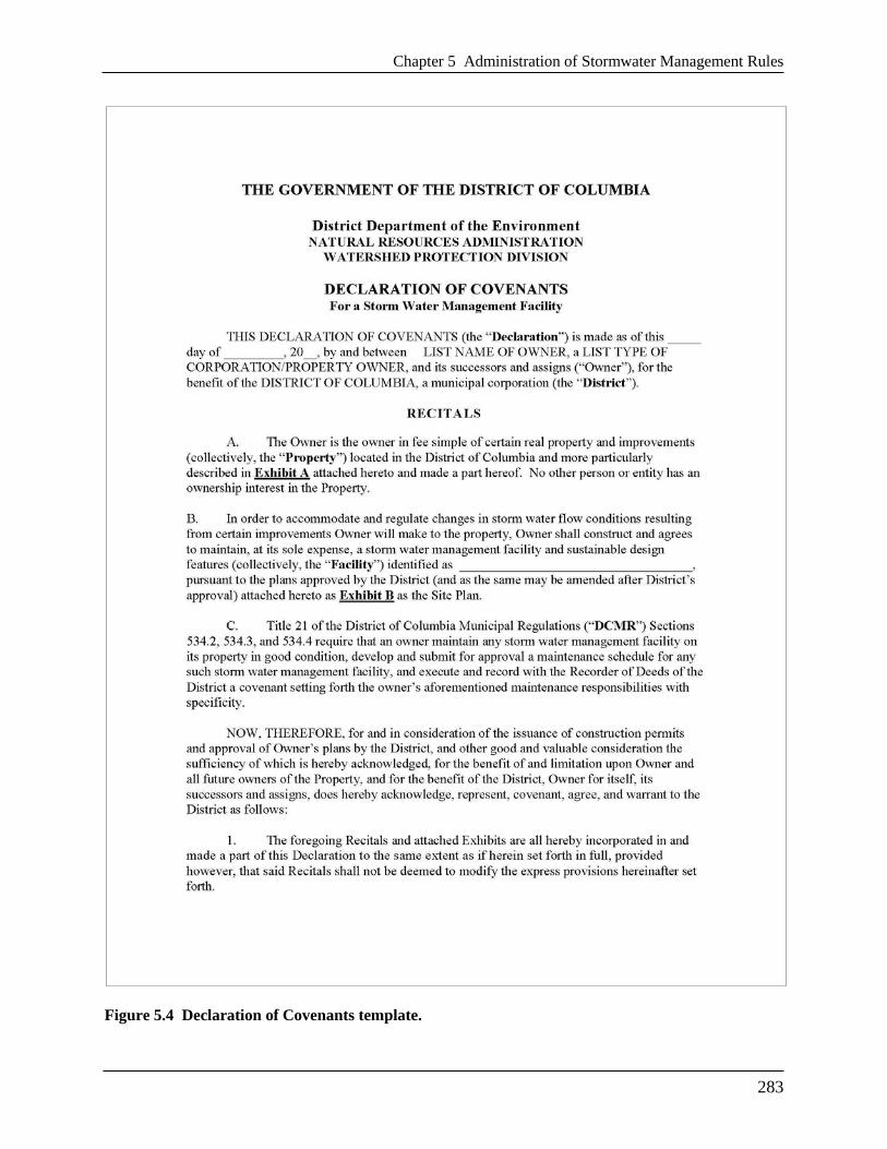
Chapter 5 Administration of Stormwater Management Rules
283
Figure 5.4 Declaration of Covenants template.
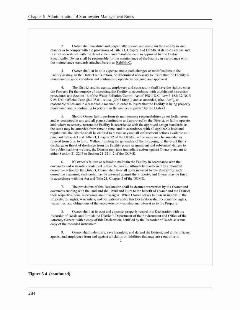
Chapter 5 Administration of Stormwater Management Rules
284
Figure 5.4 (continued)

Chapter 5 Administration of Stormwater Management Rules
285
Figure 5.4 (continued)

Chapter 5 Administration of Stormwater Management Rules
286
Figure 5.4 (continued)

Chapter 5 Administration of Stormwater Management Rules
287
Figure 5.4 (continued)

Chapter 5 Administration of Stormwater Management Rules
288
Figure 5.4 (continued)

Chapter 5 Administration of Stormwater Management Rules
289
5.7 Flow Diagram of Plan Review Process
Flow charts, in Figures 5.1 through 5.4 illustrate the five steps in DDOE’s review of a
Stormwater Management Plan (SWMP) and Soil Erosion and Sediment Control Plan in the
context of the overall permitting process, which includes the Environmental Impact Statement
Form (EISF) process.
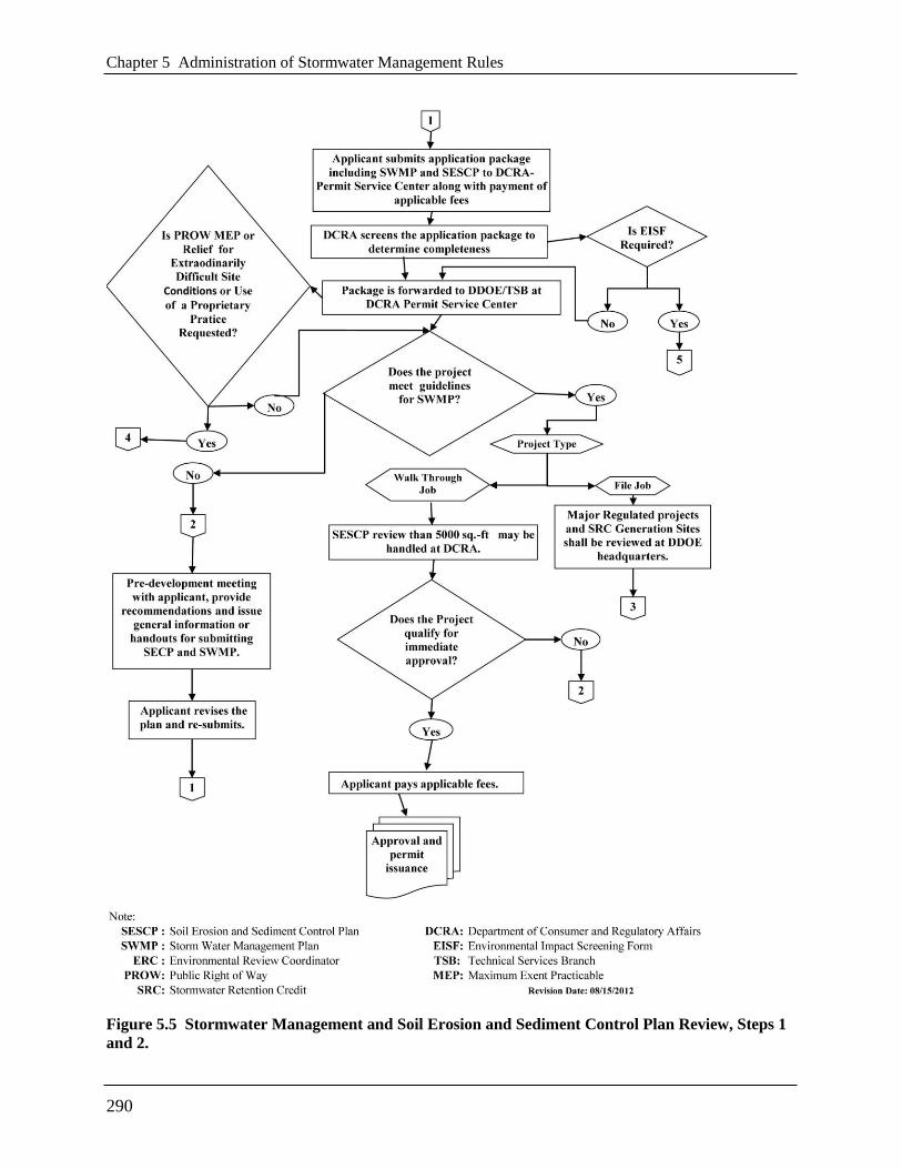
Chapter 5 Administration of Stormwater Management Rules
290
Figure 5.5 Stormwater Management and Soil Erosion and Sediment Control Plan Review, Steps 1
and 2.

Chapter 5 Administration of Stormwater Management Rules
291
Figure 5.6 Stormwater Management and Soil Erosion and Sediment Control Plan Review, Step 3.
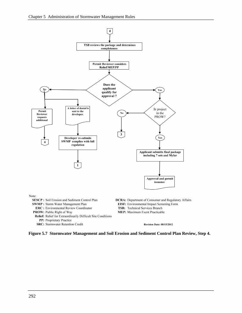
Chapter 5 Administration of Stormwater Management Rules
292
Figure 5.7 Stormwater Management and Soil Erosion and Sediment Control Plan Review, Step 4.
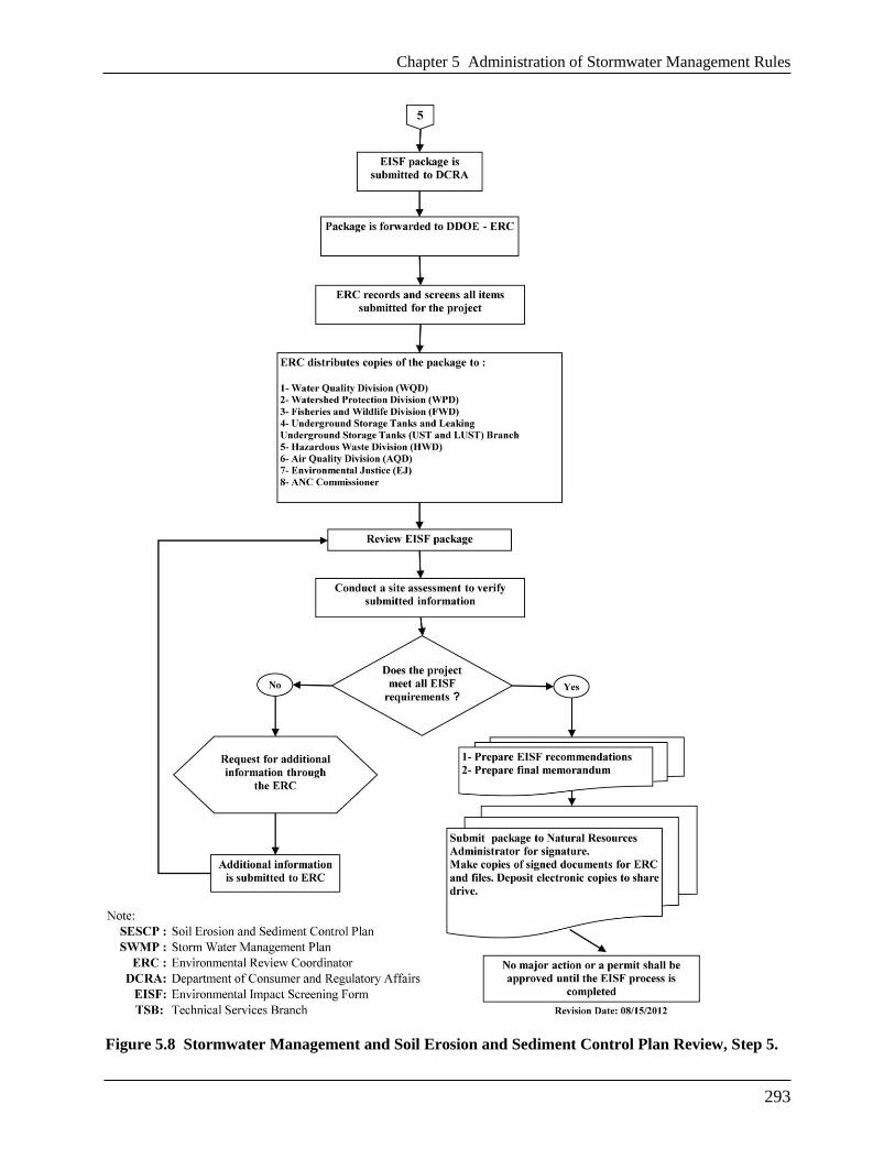
Chapter 5 Administration of Stormwater Management Rules
293
Figure 5.8 Stormwater Management and Soil Erosion and Sediment Control Plan Review, Step 5.


295
Chapter 6 Use of Off-Site Retention by
Regulated Sites
6.1 Off-Site Retention Overview
A regulated site must retain a minimum volume on site that is equal to 50 percent of the SWRv.
Above that minimum on-site volume, the regulated site may use off-site retention without having
to first demonstrate that it would be infeasible to retain that volume on site. However, in order to
retain less than the minimum on-site volume, the site must demonstrate that on-site retention of
that volume is technically infeasible or environmentally harmful.
The portion of a SWRv that a regulated site does not retain on site is termed the Off-Site
Retention Volume or Offv, and a regulated site’s options for achieving its Offv are the following:
a. Use Stormwater Retention Credits (SRCs), each of which corresponds to one gallon of
retention for one year; or
b. Pay DDOE’s in-lieu fee (ILF), the cost of which corresponds to one gallon of retention for
one year; or
c. A combination of (a) and (b).
The owner of a regulated site may use SRCs that the owner has earned elsewhere in the District
or SRCs purchased on the private market. DDOE will provide the regulated site with contact
information for SRC owners who wish to sell their SRCs. SRC buyers and sellers negotiate the
terms of a transaction between themselves, but the transaction is not complete until DDOE has
approved it. DDOE’s approval is required so that DDOE can effectively track ownership and
use, including preventing fraudulent use of SRCs, and also publicly share the price at which
SRCs sell.
Regulated sites are responsible for their Offv on an ongoing basis, just as they must maintain any
on-site stormwater best management practices (BMPs) on an ongoing basis. In other words, they
must continue to use SRCs or pay in-lieu fee for the life of the development, similar to paying a
lease or utility fee. However, if in the future a regulated site retrofits and achieves its Offv on
site, then it no longer must achieve that volume off site.
A regulated site may meet its Offv for multiple years by paying up front for sufficient in-lieu fee
to satisfy its Offv for that time period. Likewise, the regulated site may purchase and commit to
use sufficient SRCs to satisfy its Offv for multiple years. SRCs may be banked indefinitely. The
one year lifespan of an SRC or in-lieu fee payment begins once it is used to satisfy an Offv.
Once SRCs have been used or sold, they remain valid, even if the owner of the retention
practices for which SRCs were certified fails to maintain them. Note, however, that there are
consequences for original SRC owners who fail to maintain retention practices for which SRCs
have been certified, as discussed in Chapter 7 and Appendix D.
Chapter 6 Use of Off-Site Retention by Regulated Sites
296
Each SRC will have a unique serial number, and DDOE will track how a regulated site is
satisfying its Offv. DDOE will automatically assess an in-lieu fee, with penalties for late
payment, for any site that does not stay current with its Offv obligation. DDOE may also take
other action, including enforcement action, against a regulated site for failure to comply with an
Offv.
The Stormwater Management Plan (SWMP) for a regulated site opting to use off-site retention
must state its Offv. This Offv, along with related requirements for sites in the Anacostia
Waterfront Development Zone, will be recorded in the declaration of covenants filed for the
property. Whether using in-lieu fee or SRC, they must be in use as of the successful completion
of DDOE’s final inspection at the end of the construction process.
6.2 Off-Site Retention via Stormwater Retention Credits
One SRC satisfies one gallon of Off-Site Retention Volume (Offv) for one year. The use of an
SRC is not restricted by watershed. However, for every gallon of Offv that an Anacostia
Waterfront Development Zone (AWDZ) site elects to meet with SRCs from outside the
Anacostia River watershed, it must use 1.25 SRCs.
A regulated site with an Offv may elect at a future date to install additional stormwater best
management practices (BMPs) on site in a sufficient volume to eliminate or reduce the Offv.
To use SRCs to meet an Offv, a regulated site owner must submit an application to use SRCs to
meet its Offv (see Appendix C). The application must identify SRCs that are owned by the site
owner and may cover multiple years of Offv. The application must be submitted 30 days in
advance of the planned date of use. SRCs (and/or in-lieu fee) must be in use as of the successful
completion of DDOE’s final inspection at the end of the construction process and thereafter on
an ongoing basis.
After verifying the ownership of the SRCs and other information in the application to use SRCs,
DDOE will approve the use of the SRCs. DDOE will not sign off on a regulated site’s final
inspection at the end of the construction process until it has approved the application and verified
that any Offv is achieved. The one-year lifespan of the SRCs begins as of the date that it is used
to meet the Offv.
At least 30 days before SRCs used to satisfy an Offv are set to expire, the regulated site owner
must submit an application identifying additional SRCs that will be used to satisfy the Offv or
pay in-lieu fee.
If DDOE does not receive an application to use SRCs or an in-lieu fee payment and a lapse in
compliance with an Offv occurs, DDOE shall charge an in-lieu fee, with a 10 percent late fee, to
the regulated site owner and provide notice to the site owner accordingly. For a site owner who
does not comply within 30 days of DDOE’s notice of a lapse in satisfaction of an Offv obligation
and who owns an SRC that has not been used to satisfy the Offv for another site, DDOE may
apply that SRC to the Offv that is out of compliance. DDOE may also take enforcement action
against a regulated site that fails to comply with an Offv.
Chapter 6 Use of Off-Site Retention by Regulated Sites
297
Summary of Key Steps for Using SRCs
Step 1: Apply to use SRCs to satisfy Offv 30 days in advance of final construction
inspection.
Step 2: Receive DDOE approval of use of SRCs.
Step 3: Schedule final construction inspection with DDOE (Steps 2 and 3 can be reversed).
Step 4: Pass final construction inspection and start use of SRCs.
Step 5: 30 days before SRC expiration, apply to use additional SRCs to satisfy Offv.
Step 6: Receive DDOE approval of use of SRCs.
Step 7: Repeat Steps 5 and 6 as necessary.
6.3 Off-Site Retention via In-Lieu Fee
In-lieu fee corresponds to one gallon of retention for one year. Payment of one gallon worth of
in-lieu fee satisfies one gallon of Off-Site Retention Volume (Offv) for one year. A regulated site
may elect to install additional BMPs on site in a sufficient volume to eliminate or reduce the
Offv.
To use in-lieu fee to meet an Offv, a regulated site must submit payment to the District, along
with a notification form (see Appendix C). The notification and payment may be for multiple
years. The notification and payment must be submitted 30 days in advance of the planned date of
use. In-lieu fee (and/or SRCs) must be in use as of the successful completion of DDOE’s final
inspection at the end of the construction process and thereafter on an ongoing basis.
DDOE will confirm receipt of in-lieu fee. DDOE will not sign off on a regulated site’s final
inspection at the end of the construction process until it has verified that its Offv is achieved. The
one-year lifespan of the in-lieu fee begins as of the date that it is used to meet Offv.
If DDOE does not receive an application to use SRCs or an in-lieu fee payment and a lapse in
compliance with an Offv occurs, DDOE shall charge an in-lieu fee, with a 10 percent late fee, to
the regulated site owner and provide notice to the site owner accordingly. For a site owner who
does not comply within 30 days of DDOE’s notice of a lapse in satisfaction of an Offv obligation
and who owns an SRC that has not been used to satisfy the Offv for another site, DDOE may
apply that SRC to the Offv that is out of compliance. DDOE may also take enforcement action
against a regulated site that fails to comply with an Offv.
6.4 Forms for Use of Off-site Retention
See Appendix C for the following forms for use by the applicant:
Application to Use Stormwater Retention Credits for Off-Site Retention Volume
Notification of In-Lieu Fee Payment


299
Chapter 7 Generation, Certification, Trading,
and Retirement of Stormwater
Retention Credits
7.1 Stormwater Retention Credits Overview
This chapter provides details on the eligibility requirements for certification of Stormwater
Retention Credits (SRCs); the administrative process for certifying SRCs; the format for SRC
serial numbers; the consequences for failure to maintain SRC-generating retention capacity;
buying and selling SRCs; and voluntary retirement of SRCs. The chapter also explains how to
calculate SRCs using DDOE’s SRC Calculator and provides some example calculations.
The following background, covered elsewhere in this Guidebook and the regulations, may be
helpful in reviewing this chapter:
One Stormwater Retention Credit (SRC) is equal to one gallon of retention for one year.
One SRC can be used by a major regulated project to achieve one gallon of its Off-Site
Retention Volume (Offv) for one year.
The clock starts on an SRC’s one-year lifespan when it is used to satisfy an Offv.
An unused SRC can be banked for future use without expiring.
An SRC can be traded.
An SRC can be voluntarily retired without being used.
7.2 Eligibility Requirements
DDOE will certify Stormwater Retention Credits (SRCs) for eligible stormwater best
management practices (BMPs) and land cover in the District of Columbia. To be eligible, the
retention capacity in a BMP or land cover must do the following:
Achieve retention volume in excess of regulatory requirements, but less than the SRC
ceiling;
For unregulated projects or voluntary stormwater retrofits, achieve retention volume in
excess of preproject retention but less than the SRC ceiling;
Be designed and installed in accordance with a DDOE-approved Stormwater Management
Plan (SWMP) and the Stormwater Management Guidebook;
Pass a post-construction inspection and ongoing maintenance inspections; and
Provide a maintenance contract or maintenance agreement(s) for ongoing maintenance.

Chapter 7 Generation, Certification, Trading, and Retirement of Stormwater Retention Credits
300
In addition, retention capacity installed must have been installed after May 1, 2009 in order to be
eligible.
7.2.1 Eligibility Requirements: Retention Volume
To be eligible, retention capacity must achieve retention in excess of stormwater management
regulatory requirements or, for unregulated sites, in excess of preproject retention.
For sites required to achieve a Stormwater Retention Volume (SWRv), eligible retention volume
is the volume achieved in excess of the SWRv, but less than the SRC ceiling as shown in Figure
7.1.
For sites required to treat a water quality treatment volume (prior to establishment of SWRv
requirements), eligible retention volume is the volume retained in excess of the stormwater
treatment requirements in place at that time. For example, for a regulated site that provided
treatment for the 0.5-inch storm by installing BMPs capable of retaining the 0.9-inch storm, the
eligible retention volume would be the difference between the 0.9-inch storm volume and the
0.5-inch storm volume (i.e., 0.4-inch storm volume).
For sites that are unregulated or that would only trigger the regulations because of the voluntary
installation of retention capacity, eligible retention volume is the volume achieved in excess of
preproject on-site retention, as shown in Figure 7.1.
Guidance on calculating volume eligibility of retention capacity for certification of SRCs is
below, and an SRC calculation spreadsheet is available on DDOE’s website.
In all cases, DDOE shall not certify SRCs for retention capacity in excess of the runoff volume
expected to occur from a 1.7 inch rainfall event (―SRC Ceiling‖) (see Figure 7.1),

Chapter 7 Generation, Certification, Trading, and Retirement of Stormwater Retention Credits
301
2: Unregulated Sites Exceeding Existing Retention
Stormwater
Retention Credit
1: Regulated Sites Exceeding Required Stormwater
Retention Volume (SWRv) on Site
SRC Ceiling 1.7 inch storm
Required SWRv1.2 inch storm (0.8 inch for
substantial improvement projects)
Post-development
site without BMPs
SRC Ceiling 1.7 inch storm
Existing site retention
prior to new BMPs
Stormwater
Retention Credit
Figure 7.1 Retention volume eligible to earn SRCs.
7.2.2 Eligibility Requirements: Design and Installation
To be eligible for SRC certification, retention BMPs or land covers must be designed and
installed according to a DDOE-approved SWMP, with an as-built SWMP submitted to DDOE.
DDOE recognizes that some retention capacity, voluntarily installed prior to the establishment of
retention standards, was installed without obtaining DDOE approval of a SWMP prior to
installation. This retention capacity may still be eligible to earn SRCs. In such cases, DDOE will
require an as-built SWMP stamped by a professional engineer licensed in the District of
Columbia, as well as documentation of existing site conditions prior to the installation of the
retention capacity. DDOE will consider such Applications for Certification of SRCs on a case-
by-case basis and will determine eligible retention capacity in accordance with the specifications
in this Stormwater Management Guidebook.

Chapter 7 Generation, Certification, Trading, and Retirement of Stormwater Retention Credits
302
7.2.3 Eligibility Requirements: Inspection
To be eligible for SRC certification, retention BMPs and land covers must pass DDOE’s post-
construction inspection and continue to pass inspections on an ongoing basis. DDOE typically
inspects BMPs every three years but may also conduct unscheduled inspections of retention
capacity, on a random basis or as a result of a potential problem that is identified by DDOE or
the public.
7.2.4 Eligibility Requirements: Maintenance
To be eligible for SRC certification, retention capacity must be maintained in good working
order, as specified by DDOE. In an application for certification of SRCs, the proposed SRC
owner (who becomes the original SRC owner once DDOE certifies the SRCs) signs a statement
swearing to maintain the retention capacity for the period of time for which SRC certification is
requested. To demonstrate the commitment to maintenance, the applicant must submit a current
maintenance contract for the time period for which SRC certification is requested. Alternatively,
applicants may conduct this maintenance, but they must demonstrate that they have the expertise
and capacity to conduct the maintenance. The applicant shall submit the maintenance contract or
other documentation of expertise and capacity as an attachment to the application for
certification of SRCs.
7.3 Certification of Stormwater Retention Credits
DDOE will accept applications for certification of SRCs once the regulations related to
certification and ownership of SRCs are finalized in the D.C. Register. Required supporting
documentation for the initial application includes the completed SRC calculation spreadsheet, as-
built SWMP, and signed maintenance agreement or contract. Applications for retention capacity
installed without prior DDOE approval of a SWMP must also provide documentation of site
conditions prior to installation, including land cover type and existing retention BMPs. (See
Chapter 2 and Appendix A for Stormwater Retention Volume calculations.)
Appendix D contains the application form for certification of SRCs. Through the form, DDOE
receives information that is necessary to track and record generated SRCs. Such information
includes the address of the site with eligible retention capacity, the owner of proposed SRCs, and
the owner’s agent, among other information. Applicants should note the format for submitting
information on the drainage areas and BMPs that will generate SRCs on a site. Applicants should
assign each drainage area a letter (e.g., A, B, C) and each BMP a corresponding number (e.g.,
A1, B2, C3).
DDOE will review the application and supporting documentation to make a determination as to
the number of SRCs to certify. DDOE will send its response to the proposed SRC owner who is
listed on the application for certification. DDOE expects that the proposed SRC owner would
very often be both the owner of the retention capacity and the owner of the property, but
recognizes that this may not always be the case. If the proposed SRC owner is not the property
owner, the proposed SRC owner must include documentation of the right to own the SRC
applied for.

Chapter 7 Generation, Certification, Trading, and Retirement of Stormwater Retention Credits
303
DDOE will certify up to three years’ worth of SRCs for eligible retention capacity (the three-
year period is based on DDOE’s typical three-year inspection cycle). DDOE will assign each
SRC a unique serial number for tracking purposes. At the end of that three-year period, the
owner may apply for another three years’ worth of SRCs. For example, for 1,000 gallons of
eligible retention capacity, DDOE will certify up to 3,000 SRCs initially and an additional 3,000
SRCs at the beginning of each subsequent three-year period, as long as the eligibility
requirements continue to be met.
An applicant should only apply for certification of SRCs corresponding to the period for which
maintenance is planned. In applying for SRCs, an applicant commits to the maintenance of the
retention capacity for the time period for which SRC certification is requested. Failure to
maintain SRC-generating retention capacity is discussed below.
An applicant who wishes to have SRCs certified after the initial period of certification shall re-
submit an application for certification of SRCs. The required supporting documentation for this
re-submittal is a current maintenance contract or documentation of ongoing expertise and
capacity to conduct the maintenance. DDOE expects to issue additional SRCs for retention
capacity that has passed re-inspection and for which a submitted the commitment to maintain has
been demonstrated.
Key Milestones for the Generation of SRCs:
1. Receive DDOE approval of proposed SWMP.
2. Install BMPs and/or land covers.
3. Pass DDOE’s post-construction inspection.
4. Submit application for DDOE certification of SRCs, including:
(a) As-built SWMP;
(b) Current maintenance contract or documentation of expertise and capacity to conduct
maintenance; and
(c) Documentation of the legal right to the SRCs applied for, if the proposed SRC owner is
not the property owner.
5. Receive DDOE certification for up to three years’ worth of SRCs.
6. Maintain retention capacity and pass subsequent inspections.*
7. Submit application for DDOE certification of SRCs, including:
(a) Current maintenance contract or documentation of expertise and capacity to conduct
maintenance and.
(b) Documentation of the legal right to the SRCs applied for, if the proposed SRC owner is
not the property owner.*
8. Receive DDOE certification for up to three years’ worth of additional SRCs.*
*Steps 6, 7, and 8 can be repeated indefinitely

Chapter 7 Generation, Certification, Trading, and Retirement of Stormwater Retention Credits
304
7.4 Format of SRC Serial Numbers
RC serial numbers are based on the following format:
For example, a proposed SRC owner submits a complete application for certification of SRCs on
January 1, 2014 for 1,000 gallons of eligible retention capacity located in the Watts Branch sub-
drainage of the Anacostia River. The retention capacity was installed in accordance with a
DDOE-approved SWMP with ―1400‖ as the identification number. After approving the
application for three years’ worth of SRCs, DDOE would issue 3,000 SRCs as follows:
1,000 SRCs 20140101-A19-01400-000001 -
20140101-A19-01400-001000
1,000 SRCs 20150101-A19-01400-000001 -
20150101-A19-01400-001000
1,000 SRCs 20160101-A19-01400-000001 -
20160101-A19-01400-001000
This example assumes Watts Branch has been assigned ―19‖ as an identifying number, but the
numbering of sub-drainages has not been finalized. When the list of each sub-drainage’s
identifying number is final, DDOE will post it on its website.
7.5 Failure to Maintain Retention after Certification of Stormwater
Retention Credits
Sites need not file a declaration of covenants for the maintenance of retention capacity for which
DDOE has certified SRCs. However, DDOE will not certify additional SRCs for retention
capacity that is not maintained. Furthermore, original SRC owners will be required to
compensate for the associated retention failure during the time period for which maintenance did
not occur by doing one of the following: 1) forfeiting those SRCs (if they have not been sold or
used); 2 purchasing replacement SRCs that DDOE will then retire; or 3) paying in-lieu fee to
DDOE.
7.6 Buying and Selling Stormwater Retention Credits
Each SRC has a unique serial number, and DDOE will track the ownership and use of each SRC.
Before the ownership of an SRC can be officially transferred, DDOE must approve a completed
application for transfer of SRC ownership in order to verify the ownership and status of the
SRCs. The new owner of the SRCs cannot use the SRCs to meet an Offv until DDOE has
approved the application.
Beginning of certification year
(yyyymmdd)
Major and Sub drainage
(A,R,P and 2 digits)
SWMP number
(5 digits)
Individual gallon of capacity
(6 digits) - - -
Chapter 7 Generation, Certification, Trading, and Retirement of Stormwater Retention Credits
305
SRCs can be banked for future use without expiring. The one-year lifespan of an SRC begins
once it is used to achieve an Offv.
Key Milestones in Transfer of SRC Ownership
1. Negotiate terms of transfer/contract between buyer and seller.
2. Submit application for transfer of SRC ownership to DDOE.
3. Receive DDOE confirmation of transfer of SRC ownership.
7.7 Voluntary Retirement of Stormwater Retention Credits
An SRC owner can request that an SRC be retired by submitting an application to retire SRCs.
7.8 Quitting the Obligation to Maintain Retention for Stormwater
Retention Credits
An original SRC owner can quit the obligation to maintain retention capacity for which an SRC
is certified. If the SRC has not been sold or used to satisfy an Offv, the owner may submit an
application to retire the SRC. If the SRC was sold or used, the original owner may request that
DDOE retire another SRC in its place or pay the in-lieu fee to compensate.
7.9 Calculation of Stormwater Retention Credits
A person should use DDOE’s SRC calculator spreadsheet, available on DDOE’s website, to
calculate the retention capacity on a site that meets the retention volume eligibility requirement.
As discussed above, retention capacity must also meet eligibility requirements for design and
installation; inspection; and maintenance in order for DDOE to certify SRCs.
Use of the SRC calculator spreadsheet is discussed below. The calculator allows SRC calculation
for multiple drainage areas on a site.
Note that major regulated projects that are interested in exceeding the required SWRv in order to
generate SRCs should input data in the SRC calculator’s Existing Retention section based on the
proposed site conditions upon achievement of the SWRv. Any changes to land cover and
retention above and beyond the SWRv should be input in the Proposed Retention section.
Scenario 3 in Section 7.9 is an example of a major regulated project that exceeds the SWRv in
order to generate SRCs.
On the SRC calculator spreadsheet, cells highlighted in blue are user input cells. Cells
highlighted in gray are calculation cells, and cells highlighted in yellow are constant values.
The steps given below are meant to be followed while working with DDOE’s SRC calculator
spreadsheet. Note that only entry of input data is required by users—no manual calculations
are required except when more than 4 BMPs are present or proposed in each drainage area for
Steps 1(c) and 2(c) (adding up BMP retention). The equations utilized in the spreadsheet are
given below for informational purposes.

Chapter 7 Generation, Certification, Trading, and Retirement of Stormwater Retention Credits
306
Step 1: Determine Preproject Retention for Drainage Area 1.
a. Input area of each preproject land cover, including Impervious Cover, Compacted Cover, and
Natural Cover in lines 14–16. Guidance for various land covers is provided in Appendix N
and Table A.1 of Appendix A.
b. Automatic calculation of retention provided by preproject land cover. This is equivalent to
the abstraction provided by the land, determined by modifying the formula for calculating the
SWRv. The calculation applies a retention coefficient (0.05 for Impervious Cover, 0.75 for
Compacted Cover, and 1.0 for Natural Cover) to each of the land cover areas, using the 1.7-
inch storm depth. (line 17).
48.712
0.175.005.0 PC
ENAECCAEIAERLC
where:
ERLC = retention from the existing (preproject) land cover (gal) (line 17)
EIA = existing (preproject) impervious cover area (ft2) (line 14)
ECCA = existing (preproject) compacted cover area (ft2) (line 15)
EN = existing (preproject) natural cover area (ft2) (line 16)
PC = precipitation ceiling (in.) (line 10)
c. Input each existing retention BMP in lines 20–23. If there are more than four existing BMPs,
sum the additional BMP retention volumes (for example, BMP 4 + BMP 5 + BMP 6 + …) by
drainage area in the last row (line 23).
d. Automatic calculation of the total existing retention as sum of existing retention by land (line
17) and existing retention by BMPs (lines 20 through 23). (line 25).
.,6,5,4321 etcPPPPLCT ERERERERERER
where:
ERT = total existing (preproject) retention (gal) (line 25)
ERLC = retention from the existing (preproject) land cover (gal) (line 17)
ERP1 = retention from first existing (preproject) BMP (gal) (line 20)
ERP2 = retention from second existing (preproject) BMP (gal) (line 21)
ERP3 = retention from third existing (preproject) BMP (gal) (line 22)
ERP4, 5, 6, etc. = retention from third existing (preproject) BMP (gal) (line 23)
Step 2: Determine Proposed Retention for Drainage Area 1.
a. Input the proposed land cover including Impervious Cover, Compacted Cover, and Natural
Cover in lines 28-30. Guidance for various land covers is provided in Table A.1 and
Appendix N.
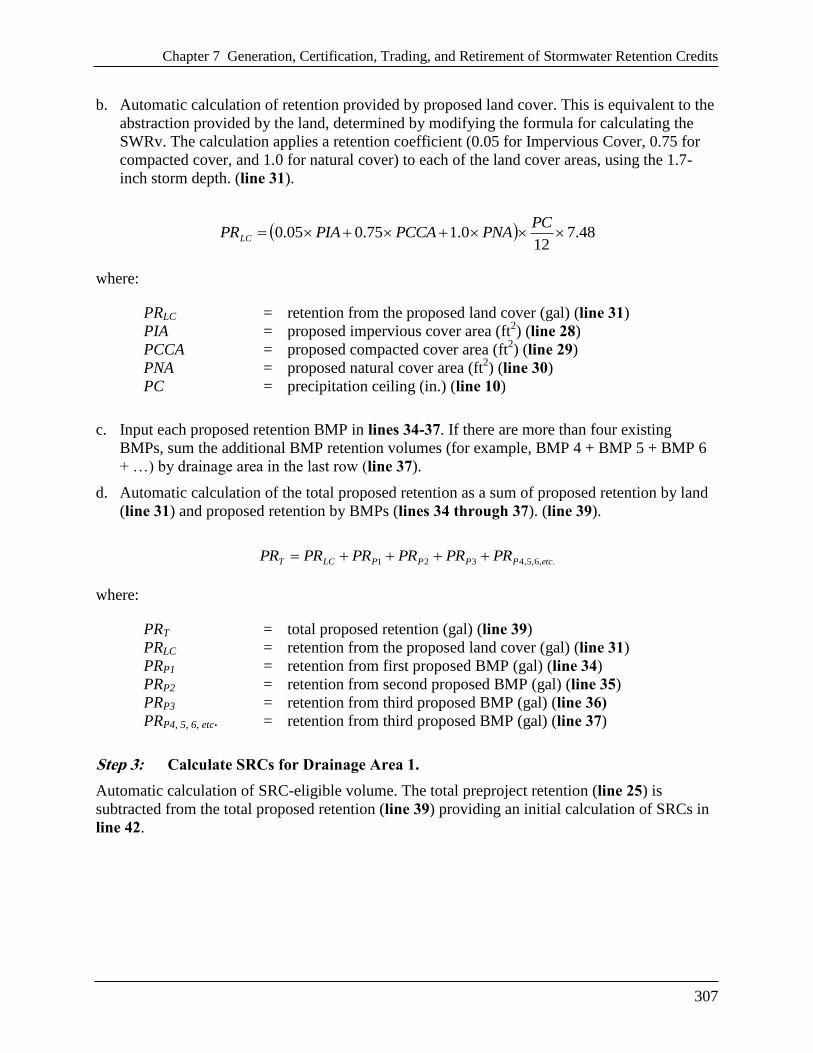
Chapter 7 Generation, Certification, Trading, and Retirement of Stormwater Retention Credits
307
b. Automatic calculation of retention provided by proposed land cover. This is equivalent to the
abstraction provided by the land, determined by modifying the formula for calculating the
SWRv. The calculation applies a retention coefficient (0.05 for Impervious Cover, 0.75 for
compacted cover, and 1.0 for natural cover) to each of the land cover areas, using the 1.7-
inch storm depth. (line 31).
48.712
0.175.005.0 PC
PNAPCCAPIAPRLC
where:
PRLC = retention from the proposed land cover (gal) (line 31)
PIA = proposed impervious cover area (ft2) (line 28)
PCCA = proposed compacted cover area (ft2) (line 29)
PNA = proposed natural cover area (ft2) (line 30)
PC = precipitation ceiling (in.) (line 10)
c. Input each proposed retention BMP in lines 34-37. If there are more than four existing
BMPs, sum the additional BMP retention volumes (for example, BMP 4 + BMP 5 + BMP 6
+ …) by drainage area in the last row (line 37).
d. Automatic calculation of the total proposed retention as a sum of proposed retention by land
(line 31) and proposed retention by BMPs (lines 34 through 37). (line 39).
.,6,5,4321 etcPPPPLCT PRPRPRPRPRPR
where:
PRT = total proposed retention (gal) (line 39)
PRLC = retention from the proposed land cover (gal) (line 31)
PRP1 = retention from first proposed BMP (gal) (line 34)
PRP2 = retention from second proposed BMP (gal) (line 35)
PRP3 = retention from third proposed BMP (gal) (line 36)
PRP4, 5, 6, etc. = retention from third proposed BMP (gal) (line 37)
Step 3: Calculate SRCs for Drainage Area 1.
Automatic calculation of SRC-eligible volume. The total preproject retention (line 25) is
subtracted from the total proposed retention (line 39) providing an initial calculation of SRCs in
line 42.

Chapter 7 Generation, Certification, Trading, and Retirement of Stormwater Retention Credits
308
TTT ERPRPAR
where:
PART = proposed additional retention (gal) (line 42)
PRT = total proposed retention (gal) (line 39)
ERT = total existing (preproject) retention (gal) (line 25)
Step 4: Verify SRC-Eligible Volume Against Maximum Allowable for Drainage Area 1.
a. Automatic calculation of SRCCeiling, based on runoff from preproject land cover, with P
= 1.7 inches (line 45).
48.712
025.095.0 PC
ENAECCAEIASRCCeiling
where:
SRCCeiling = Stormwater Retention Credit ceiling (gal) (line 45)
EIA = existing (preproject) impervious cover area (ft2) (line 14)
ECCA = existing (preproject) compacted cover area (ft2) (line 15)
ENA = existing (preproject) natural cover area (ft2) (line 16)
PC = precipitation ceiling (in.) (line 10)
b. Automatic calculation of maximum allowable number of SRCs. SRCs shall not exceed
maximum allowable SRCs, as defined by the difference between the SRC Ceiling and the
sum of Preproject BMP Retention (line 46).
.,6,5,4321 etcPPPPCeilingMaximum ERERERERSRCSRC
where:
SRCMaximum = maximum Stormwater Retention Credit allowable (gal) (line 46)
SRCCeiling = Stormwater Retention Credit ceiling (gal) (line 45)
ERP1 = retention from first existing (preproject) BMP (gal) (line 20)
ERP2 = retention from second existing (preproject) SBMP (gal) (line 21)
ERP3 = retention from third existing (preproject) BMP (gal) (line 22)
ERP4, 5, 6, etc. = retention from third existing (preproject) BMP (gal) (line 23)
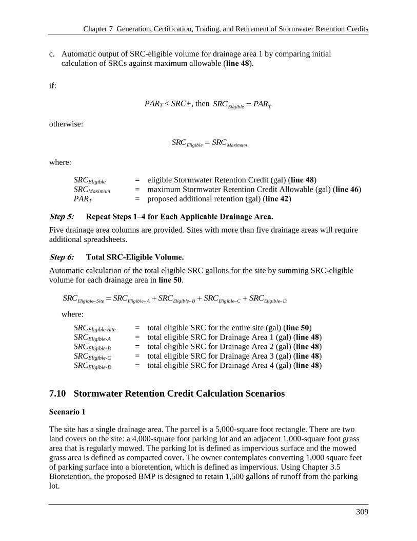
Chapter 7 Generation, Certification, Trading, and Retirement of Stormwater Retention Credits
309
c. Automatic output of SRC-eligible volume for drainage area 1 by comparing initial
calculation of SRCs against maximum allowable (line 48).
if:
PART < SRC+, then TEligible PARSRC
otherwise:
MaximumEligible SRCSRC
where:
SRCEligible = eligible Stormwater Retention Credit (gal) (line 48)
SRCMaximum = maximum Stormwater Retention Credit Allowable (gal) (line 46)
PART = proposed additional retention (gal) (line 42)
Step 5: Repeat Steps 1–4 for Each Applicable Drainage Area.
Five drainage area columns are provided. Sites with more than five drainage areas will require
additional spreadsheets.
Step 6: Total SRC-Eligible Volume.
Automatic calculation of the total eligible SRC gallons for the site by summing SRC-eligible
volume for each drainage area in line 50.
DEligibleCEligibleBEligibleAEligibleSiteEligible SRCSRCSRCSRCSRC
where:
SRCEligible-Site = total eligible SRC for the entire site (gal) (line 50)
SRCEligible-A = total eligible SRC for Drainage Area 1 (gal) (line 48)
SRCEligible-B = total eligible SRC for Drainage Area 2 (gal) (line 48)
SRCEligible-C = total eligible SRC for Drainage Area 3 (gal) (line 48)
SRCEligible-D = total eligible SRC for Drainage Area 4 (gal) (line 48)
7.10 Stormwater Retention Credit Calculation Scenarios
Scenario 1
The site has a single drainage area. The parcel is a 5,000-square foot rectangle. There are two
land covers on the site: a 4,000-square foot parking lot and an adjacent 1,000-square foot grass
area that is regularly mowed. The parking lot is defined as impervious surface and the mowed
grass area is defined as compacted cover. The owner contemplates converting 1,000 square feet
of parking surface into a bioretention, which is defined as impervious. Using Chapter 3.5
Bioretention, the proposed BMP is designed to retain 1,500 gallons of runoff from the parking
lot.

Chapter 7 Generation, Certification, Trading, and Retirement of Stormwater Retention Credits
310

Chapter 7 Generation, Certification, Trading, and Retirement of Stormwater Retention Credits
311
Scenario 2
The site has a single drainage area. The parcel is a 5,000-square foot rectangle and is divided
between a 4,500-square foot parking lot and an adjacent 400-square foot grass area that is
regularly mowed. There is an existing bioretention (the land areas of all BMPs are considered
impervious) covering 100 square feet and determined to retain 1,000 gallons using Chapter 3.5.
The parking lot is defined as impervious surface and the mowed grassy area is defined as
compacted cover. The owner contemplates converting the grass area into bioretention and
reducing the parking lot size by 1,000 square feet, with that area converted into mowed grass.
Using Chapter 3.5 Bioretention, the proposed 400-square foot BMP is designed to retain 1,500

Chapter 7 Generation, Certification, Trading, and Retirement of Stormwater Retention Credits
312
gallons of runoff from the parking lot in addition to the 1,000 gallons retained by the original
BMP.

Chapter 7 Generation, Certification, Trading, and Retirement of Stormwater Retention Credits
313
Scenario 3
The site is a proposed development with land disturbance activities that trigger the stormwater
regulation. We limit the scenario to one of several drainage areas within the project’s limits of
disturbance. The drainage area is 5,000 square feet. It will contain a newly constructed 4,000-
square foot parking lot and an adjacent existing 700-square foot grass area that is regularly
mowed. A proposed bioretention will manage parking lot runoff and cover 300 square feet. This
bioretention will retain 3,186 gallons based on Chapter 3.5. In this scenario, these gallons are the
regulated Stormwater Retention Volume (SWRv) for this drainage area. The parking lot and the
bioretention are defined as impervious surface, and the mowed grass area is defined as

Chapter 7 Generation, Certification, Trading, and Retirement of Stormwater Retention Credits
314
compacted cover. The owner contemplates converting 700 square feet of parking lot into
bioretention to gain additional retention gallons above the regulatory obligation. Using Chapter
3.5 Bioretention, the additional 700 square feet will provide 3,000 gallons of additional retention.

Chapter 7 Generation, Certification, Trading, and Retirement of Stormwater Retention Credits
315
7.11 Forms for Stormwater Retention Credits
See Appendix D for the following forms for use by the applicant:
Application for Certification of Stormwater Retention Credits
Application for Transfer of Stormwater Retention Credit Ownership
Application to Retire Stormwater Retention Credits