Embed Size (px)
Citation preview

City of Columbia Best Management Practice (BMP)
Design Manual
Prepared for:
The City of Columbia, Utilities and Engineering Department Columbia, South Carolina
Prepared by:
AMEC Environment and Infrastructure, Inc.
720 Gracern Road Columbia, SC 29210
Date Revised: January 10 2014

CoC BMP Design Manual: Table of Contents Chapter 1 – Stormwater Design Requirements ............................................................................... 2
Figure 1.1 – Stormwater Compliance Process ........................................................................ 3 1.1 General Requirements .................................................................................................. 4 1.2 Special Protection Areas ............................................................................................... 6
1.2.1 Flooding Problem Areas ........................................................................................... 6 1.2.2 Areas Associated with TMDLs and Impaired Waterbodies ..................................... 6 1.2.3 Critical Water Bodies ................................................................................................ 7
1.3 Better Site Planning .......................................................................................................... 9 1.3.1 Stormwater Better Site Design ............................................................................... 10 1.3.2 List of Stormwater Better Site Design Practices and Techniques ......................... 10
1.4 Water Quality Control Requirements ......................................................................... 13 1.4.1 Design Requirements .............................................................................................. 13 1.4.2 General Design Procedures ..................................................................................... 15 1.4.3 Design Procedures for Impaired Waters and TMDLs ............................................ 16
Chapter 2 – Unified Sizing Criteria .............................................................................................. 19 2.1 Water Quality (WQv) ............................................................................................. 22 2.2 Channel Protection (CPv) ....................................................................................... 23 2.3 Overbank Flood Protection (Q25) ............................................................................ 28 2.4 Extreme Flood Protection (Q100) ............................................................................. 29 2.5 Water Quality Volume Peak Flow Calculation ...................................................... 30
Chapter 3 – Best Management Practices (BMPs) ......................................................................... 32 3.1 Water Quantity Control Requirements ....................................................................... 32
3.1.1 General Requirements ............................................................................................. 32 3.1.2 Accepted Quantity Controls .................................................................................... 34 3.1.3 Design Procedures .................................................................................................. 34 3.1.4 Downstream Hydrologic Assessment ..................................................................... 35 3.1.5 Routing with WQv Removed.................................................................................. 36
3.2 Accepted Water Quality BMPs .................................................................................. 37 3.2.1 General Application Controls .......................................................................... 38 3.2.2 Limited Application Controls ................................................................................. 39 3.2.3 Detention Structural Controls ................................................................................. 40 3.2.4 Not Recommended Structural Controls .................................................................. 41 3.2.5 Using Other or New Structural Stormwater Controls ............................................. 42 3.2.6 Structural Stormwater Control Pollutant Removal Capabilities ............................. 42 3.2.7 Structural Stormwater Control Selection ................................................................ 43 3.2.8 Using Structural Stormwater Controls in Series.............................................. 43 3.2.8.1 General Methodology ........................................................................................... 43 3.2.8.2 Calculation of Pollutant Removal for Structural Controls in Series ................... 45 3.2.9 On-Line Versus Off-Line Structural Controls ........................................................ 46
Chapter 4 – Site Design Stormwater Credits ......................................................................... 50 4.1 Stormwater Credits and the Site Planning Process ................................................. 51 4.2 User Fee Crediting Options .................................................................................... 56

Chapter 5 – Additional BMP Requirements .......................................................................... 56 5.1 Water Surface Dewatering .............................................................................................. 56 Appendices ............................................................................................................................ 57
A. Design Aids
• Calculation Worksheets -Volume Calculation Tool -BMP Sizing Tools for: Bioretention Infiltration Trench Dry Enhanced Swale Grass Filter Strip Porous Surfaces
• Standard CAD Details and Notes/Specs Bioretention
Infiltration Trench Dry Enhanced Swale Grass Filter Strip
Micropool Extended Dry Detention Pond Wet Detention Pond
B. Maintenance Schedules
Chapter 1 – Stormwater Design Requirements This chapter provides engineers, designers, developers, and others with the necessary information to assist with the development of systems that will control the rate, volume, and pollutants released from a new or re-development project. The City of Columbia Utilities and Engineering Department’s Stormwater Division (SWD) has been authorized by law or agreement to enforce these design requirements. These design requirements are based on Best Management Practices and reference State and Federal regulations, engineering publications, and other municipal and academic guidance. It is an overall goal of this Manual to provide a set of design standards that will result in effective stormwater management. The goal is to mitigate the impact of land development on existing/natural hydrologic and hydraulic processes, as well as attempt to prevent further degradation of the water resources in the City of Columbia through proper planning and design. The design professional is encouraged to use all means necessary to develop land in a manner consistent with City Ordinances, Engineering Regulations, and this Manual and to ensure the safety of the general public. Specific methods and applications not covered in this section must be discussed with the SWD for applicability. NOTE: In addition to the content included in this manual, the Georgia Stormwater Management Manual (GSMM) will also be utilized, which uses the same methodology – specific GSMM sections to be used are cited with links to those specific sections throughout the document.

The following process (Figure 1.1) will be described in detail throughout this Manual, and will be the basis for compliance with the City of Columbia stormwater requirements:
Develop Concept Plan Using Better Site Design Practices (Ch. 1)
Use Unified Sizing Criteria to Determine Stormwater Control and Treatment Volumes (Ch. 2)
Apply Stormwater "Credits" for Better Site Design to Reduce Volumes (Sect 3.1.5 & Ch. 4)
Final Site Plan
Perform Downstream Assessment (sect 3.1.4)
Size, Design and Site Structural Stormwater Controls (LDM Sect 3.1, 3.2, 5.2 & 5.3)
Screen and Select Appropriate Structural Stormwater Controls (sect 3.2)
Figure 1.1 – Stormwater Compliance Process

1.1 General Requirements General requirements for all stormwater systems will include, but not limited to the following:
1. The Uniform Sizing Criteria (USC) will be used as described in this Manual to address: a. The Water Quality Volume (WQv) b. The Channel Protection Volume (CPv) c. Impacts from overbank and extreme flooding events (2- through 100-year) d. Avoiding downstream water quality or quantity impacts e. Applying proper volume “credits” to a site design f. The specific design and performance requirements for each allowable BMP
2. All privately owned stormwater facilities shall have a maintenance agreement. This notarized covenant is to be recorded with the Register of Deeds in the City of Columbia.
3. Re-development is typically governed by the same design criteria as new developments, however the SWD reserves the right to alter (increase or decrease) the requirements for redevelopment to address specific conditions of the site or the receiving watershed.
4. All post-development BMPs must be protected from erosion and sedimentation during the construction phases; a final inspection by the City will be required to determine if additional action is needed to remove sediment deposits from post-construction BMPs. See Section 21-44 of the Stormwater Quantity and Quality Control Ordinance for further maintenance, construction, inspection and Notice of Termination (NOT) requirements for activities under a land disturbance permit. In cases where other City or SCDHEC sediment prevention and erosion control regulations are applicable, the most restrictive requirements will be adhered to.
5. An assessment of the presence/absence of wetlands/Waters of the State shall be performed on all sites by a qualified professional. If wetlands/Waters of the State are suspected to exist on a property, they shall be investigated and delineated by a qualified professional. If wetlands are to be impacted, the City will not issue a Land Disturbance Permit without a confirmation or denial letter from the US Army Corps of Engineers (USACE).
6. All stormwater management and sediment control practices shall be designed, constructed, and maintained with consideration for the proper control of mosquitoes and other vectors.
7. The entire watershed that drains to a particular design point shall be included in determining the appropriate design storm. All drainage systems regardless of size or classification (see sections 1.1.7 a-d below and the City of Columbia’s Utilities and Engineering Regulations for their Drainage Ordinance ) shall be analyzed and designed as necessary to safely pass the 100-year storm event to avoid the likelihood of dwelling flooding, property damage or public access and/or utility interruption.
Example 1: a residential stormwater drainage system is required to collect and convey flows from a 10-year event. However, the designer estimated the depth of flow across roadways and other surfaces during a 100-year event, which were in excess of those that catch basins and inlets could collect and convey, but would ultimately be
4

directed to the receiving stormwater pond (or waterway). Those depths of flow, for the entire site, were determined to be below those that would cause flooding (or other damages) to neighboring/adjacent properties or cause an impediment to public access and/or utility interruption. Therefore, this system safely passes the 100-year storm event.
All computations shall be based on the contributing watershed, not just the project area or disturbed area. Classification of stormwater systems are as follows according to Part 4 of the City’s Utilities and Engineering Regulations’ Drainage Ordinance (Sec. 6-5004), and will be addressed in addition to satisfying the Unified Stormwater Sizing Criteria:
a. Minor Drainage Systems: 0 - <40 Acres All drainage systems, excluding ponds that carry less than 40 acres of stormwater runoff shall be designed to carry flows resulting from a ten (10) - year storm event. Ditches and channels shall be provided to carry the runoff from a rain of fifty (50) year frequency with protection against channel erosion. b. Collector Systems: 40 - <500 Acres All drainage systems, excluding ponds, that carry at least 40 acres but less than 500 acres shall be designed to carry flows resulting from a twenty-five (25) - year storm event. c. Major Drainage Systems: 500 and more Acres All drainage systems, excluding ponds, that carry at least 500 and more acres shall be designed to carry a flow resulting from a fifty (50)-year storm event. Encroachment upon Major Drainage Channels and the adjacent overflow land shall be avoided to the maximum extent possible. d. City or FEMA Floodplains: 640 and more Acres Bridges and culverts being constructed in natural channels, creeks, or rivers draining more than 640 acres, shall be designed to carry a flow resulting from a one-hundred (100)-year storm event. Bridges and culverts shall be sized to accommodate a 50-year frequency rain fall, without increasing the depth of flow in the channel. Design of bridges and culverts shall conform to the current South Carolina State Highway Department construction specifications. Encroachment upon these channels shall be avoided to the maximum extent practicable, and new encroachments into an established floodway (excluding bridge piers) shall be avoided. The Floodplain provisions in Part 22 of the City Utility and Engineering Regulations Manual shall apply, where applicable, to drainage systems which drain 640 or more acres.
5

1.2 Special Protection Areas In an effort to address some of the most critical water resource problems that exist in the City, Special Protection Areas can be established. Those wishing to develop or redevelop lands within these protected areas will be required to comply with the minimum standards listed in the preceding sections (i.e. The Unified Stormwater Sizing Criteria) as well as a more stringent set of design criteria detailed below. These generally focus on either a water quantity or a water quality problem. For more information on areas to be considered as Special Protection Areas, contact Richland County.
1.2.1 Flooding Problem Areas Flooding problem areas exist in locations around the City where development densities have increased to the point that stormwater controls have become overwhelmed, or where controls were never adequately designed or installed to control runoff (see map located at in Appendix C). In an effort to relieve existing flooding problems, the following list of design criteria will be required in designated areas. These areas are expected to change with time. The requirement in conjunction with the enforcement of other design criteria listed in the sections above, are expected to assist in reducing these problem areas.
1. The post-development, peak discharge rates is restricted to ½ the pre-development rates for the 2, 5, 10 and 25-year storm events or to the downstream system capacity, whichever is less.
2. When deemed appropriate, the City’s SWD can require that the limits of flooding under a 100-year event be established on the site, regardless of drainage area. If such a requirement is enacted by the SWD, a hydraulic modeling methodology consistent with FEMA studies will be used.
3. When deemed appropriate, the City’s SWD can require that a downstream hydrologic (and/or hydraulic) analysis be performed to assess potential impacts to receiving properties and stormwater systems under a 100-year event, due to altered timing of released stormwater discharges (See Section 3.1.4). If such a requirement is enacted by the SWD, a hydrologic (and/or hydraulic) modeling methodology consistent with FEMA studies will be used. A more detailed discussion of this analysis is provided in Section 2.1.9 of the GSMM.
Additional criteria may be established on a case by case basis.
1.2.2 Areas Associated with TMDLs and Impaired Waterbodies In conjunction with the NPDES permitting program, SCDHEC, through delegated responsibility from EPA, must identify and mitigate impaired waterbodies. Impaired waterbodies are identified through a monitoring program, the results of which are compared against water quality standards developed to protect designated uses of individual waterbodies. Waterbodies that are not meeting water quality standards cannot be designated as fishing, swimming, recreation, and/or aquatic life areas. In accordance with Section 303 of the Clean Water Act states must release a
6

bi-annual report of impaired waterbodies. Waters listed on the 303(d) list will eventually have a TMDL developed, which represents the daily amount of a particular pollutant that a waterbody can receive and still meet the water quality standard for its designated use(s). City of Columbia’s 303(d) listed waters can be found at: http://www.scdhec.gov/environment/water/tmdl/docs/tmdl_10-303d.pdf For projects discharging to a 303(d) listed water the pollutant load reduction required along with the structural and non-structural BMPs that will be utilized to achieve that load reduction will be required to prevent further degradation. Water quality calculations must be provided to show that discharges from the site will not further degrade water quality. Procedures can be found in Section 2.4.3. If a waterbody has an established TMDL the SWD will require that a plan be implemented that uses structural and nonstructural BMPs to reduce the current loading to either a certain total load or by a percentage. The plans to address the TMDLs will contain provisions for both existing and future land uses. TMDL waters in City of Columbia can be found at: http://www.scdhec.gov/environment/water/tmdl/docs/tmdl_10-303d.pdf. Those areas affected will change as additional TMDLs are adopted, and it is the designer’s responsibility to check for updated information from SCHDEC. TMDL and 303(d) requirements listed in Section 2.4.3 only apply if the development project discharges a pollutant of concern based on the land use. For residential properties the applicable pollutants of concern include bacteria, sediment, dissolved oxygen and nutrients. For commercial properties the applicable pollutants of concern include, heavy metals, bacteria, dissolved oxygen and sediment. Note: while dissolved oxygen (DO) is not considered a “pollutant”, it is a measure of stream health/impairment. If a stream is impaired for low DO, the specific pollutants that can lead to low DO levels will be addressed.
1.2.3 Critical Water Bodies Rocky Branch Creek, Smith Branch, Gills Creek, and Pen Branch are vital water resources for the City of Columbia, providing a vast habitat for aquatic life. Criteria listed below, in addition to the requirements detailed in this Manual, will be enforced for all new development and re-development projects near these water bodies. These design requirements shall specifically apply to stormwater runoff from all new development and re-development projects that is discharged to these water bodies. The specific design requirements are as follows:
1. Water Quality:
a. All sites which disturb greater than one acre shall have a permanent water quality BMP in place to treat at least the runoff from the entire site for a 1.2-inch rainfall event. The Unified Stormwater Sizing Criteria method shall be used to determine the
7

water quality volume (WQv), as described in Chapter 2. This volume shall be released for a minimum period of 24-hours when a detention pond is used. For other BMPs that address water quality, the design criteria provided in Sections 3.2-3.4 of the GSMM will be followed.
b. All sites which disturb greater than one acre shall have a permanent water quality BMP in place to treat the Channel Protection Volume, which is associated with the 1-year storm event. The Unified Stormwater Sizing Criteria method shall be used to determine the channel protection volume CPv), as described in Chapter 2. This volume shall be released for a minimum period of 24-hours when a detention pond is used. For other BMPs which have the ability to address the channel protection volume, the design criteria provided in Sections 3.2-3.4 of the GSMM will be followed.
c. Due to lake boundary topography, it may be impractical to route all impervious areas to a water quality BMP. In such cases, exemptions for roof area and sidewalks may be allowed with documentation that every effort was made to route impervious areas to water quality BMPs to the maximum extent technically feasible. However, the water quality volume in the BMP must reflect that from the disturbed portion of the site (i.e. runoff from a 1.2-inch rainfall event). In no cases are roads and parking areas exempt. Area-weighting will be used to determine the net treatment for the water quality and channel protection volumes. Specific examples on how to qualify for credits that reduce the WQv and CPv requirements are provided in Chapter 4 of this document.
d. A pretreatment device such as a forebay, micro-pool, filter strips or vault, to remove debris and large sediments shall be constructed either as part of the water quality BMP or as a separate device. Specific sizing requirements, as provided in the GSMM, shall be followed.
e. Developments with a commercial land use or a parking lot which exceeds 2,000 ft2 must include the ability to capture hydrocarbons either in pretreatment or in the main BMP(s).
2. Erosion Prevention:
All discharge points shall include energy dissipation features which reduce velocity to a non-erosive state of 5 fps for clay and 2.5 fps for sand unless site conditions warrant further evaluation The use of level spreaders to dissipate energy and create a sheet flow discharge pattern is preferred over a single, large discharge pipe/channel. All energy dissipation measures shall be installed above the 360-foot elevation contour.
8

1.3 Better Site Planning
Through stormwater better site design practices and techniques, it is possible to reduce the amount of runoff and pollutants generated. Better site design concepts can be viewed as both water quantity and water quality management tools and can reduce the size and cost of required structural stormwater controls. The site design approach can better mimic the natural hydrologic conditions of the site, have a lower maintenance burden and provide for more sustainability. Better site design includes:
• Conserving natural features and resources
• Using lower impact site design techniques
• Reducing impervious cover
• Utilizing natural features for stormwater management
For each of the above categories, there are a number of practices and techniques that aim to reduce the impact of urban development and stormwater runoff from the site. These better site design practices are described in detail in Section 1.3. For several of the better site design practices, there is a direct economic benefit to their implementation for both stormwater quality and quantity through the application of site design “credits.” In terms of the unified stormwater sizing criteria, Table 1.1 shows how the use of nonstructural site design practices can provide a reduction in the amount of stormwater runoff required to be treated and/or controlled through the application of site design credits.
Table 1.1 Reductions or “Credits” to the Unified Stormwater Sizing Criteria through the
Use of Better Site Design Practices
Sizing Criteria Potential Benefits of the Use of Better Site Design Practices
Water Quality
(WQV)
• Better site design practices that reduce the total amount of
runoff will also reduce WQV by a proportional amount. • Certain site design practices will allow for a further
reduction to the Water Quality Volume. The site design credits are discussed in Section 3.8.
Channel Protection,
Overbank Flood Protection, and Extreme Flood
Protection
(CPV, QFP, Q100)
• The use of better site design practices that reduce the total
amount of runoff will also reduce CPV, QFP, and Q100 by a proportional amount.
• Floodplain preservation may allow waiving of overbank flood and/or extreme flood protection requirements.
9

1.3.1 Stormwater Better Site Design The first step in addressing stormwater management begins with the site planning and design process. By implementing a combination of these nonstructural approaches (aka: better site design practices), it is possible to reduce the amount of runoff and pollutants a site generates from a site and provide for some nonstructural on-site treatment and control of runoff. The goals of better site design include:
• Managing stormwater (quantity and quality) as close to the point of origin as possible and minimizing collection and conveyance
• Preventing stormwater impacts rather than mitigating them • Utilizing simple, nonstructural methods for stormwater management that are
lower cost and lower maintenance than structural controls
• Creating a multifunctional landscape
• Using hydrology as a framework for site design
The aim of better site design is to reduce the environmental impact “footprint” of the site while retaining and enhancing the owner/developer’s purpose and vision for the site. Many of the better site design concepts can reduce the size and cost of necessary drainage infrastructure and structural stormwater controls while maintaining or even increasing the value of the property. Several of the site design practices described in this section provide a calculable reduction or site design “credit” which can be applied to the unified stormwater sizing criteria requirements. The use of stormwater better site design can also have a number of other ancillary benefits including:
• Reduced construction costs
• Increased property values
• More open space for recreation
• More pedestrian friendly neighborhoods
• Protection of sensitive forests, wetlands and habitats
• More aesthetically pleasing and naturally attractive landscape
• Easier compliance with wetland and other resource protection regulations
1.3.2 List of Stormwater Better Site Design Practices and Techniques The stormwater better site design practices and techniques allowed for in this Manual are grouped into four categories and are listed below:
• Conservation of Natural Features and Resources o Preserve Undisturbed Natural Areas o Preserve Riparian Buffers o Avoid Floodplains
10

o Avoid Steep Slopes o Minimize Siting on Porous or Erodible Soils
• Lower Impact Site Design Techniques
o Fit Design to the Terrain o Locate Development in Less Sensitive Areas o Reduce Limits of Clearing and Grading o Utilize Open Space Development o Consider Creative Development Design
• Reduction of Impervious Cover
o Reduce Roadway Lengths and Widths o Reduce Building Footprints o Reduce the Parking Footprint o Reduce Setbacks and Frontages o Use Fewer or Alternative Cul-de-Sacs o Create Parking Lot Stormwater "Islands"
• Utilization of Natural Features for Stormwater Management
o Use Buffers and Undisturbed Areas o Use Natural Drainage ways Instead of Storm Sewers o Use Vegetated Swale Instead of Curb and Gutter o Drain Rooftop Runoff to Pervious Areas
More detail on each site design practice is provided in the Stormwater Better Site Design Practice Summary Sheets in subsection 1.4.2 of the GSMM. These summaries provide the key benefits of each practice, examples and details on how to apply them in site design. Site design should be done in unison with the design and layout of stormwater infrastructure in attaining stormwater management goals. Figure 1.2 illustrates the stormwater better site design process that utilizes the four better site design categories.
11

Identify Natural Features and Resources – Delineate Site Conservation Areas
Design Site Layout to Preserve Conservation Areas and Minimize Stormwater Impacts
Use Various Techniques to Reduce Impervious Cover in the Site Design
Utilize Natural Features and Conservation Areas to Manage Stormwater Quantity and Quality
Figure 1.2 - Stormwater Better Site Design Process
12

1.4 Water Quality Control Requirements Water quality control is an integral and required component of overall stormwater management systems to preserve the water resources of City of Columbia. New development and re-development projects must include controls that treat or otherwise limit the discharge of pollutants. These requirements are due to State and Federal requirements. Because this is a requirement of stormwater design, this section provides background information, references, and design standards addressing water quality. This section will utilize the better site design methods described in Section 1.3, as well as the credits described in Chapter 4, to reduce the volumes that must be treated. Note: The designer must also comply with the buffer requirements described in Section 21-46. - Watercourse Protection of the City's Stormwater Ordinance where the City buffer requirements may differ from those required by SCDHEC in the NPDES Construction General Permit (CGP), the more restrictive buffer requirements (i.e. larger) will be required.
1.4.1 Design Requirements The following design criteria are established for water quality control and shall be incorporated by the use of BMPs for a given project area unless a specific water quality waiver is granted by the City’s SWD. Incorporation of these requirements shall constitute adequate control of the discharge of the pollutants of concern.
1. All projects requiring a land disturbance permit, as defined in the City Stormwater Ordinance (Section 21-40/43), shall have permanent water quality BMPs installed according to the criteria listed in Chapter 2. Stormwater discharges to special protection areas with sensitive resources are subject to additional performance criteria (See Section 1.2).
2. Permanent water quality ponds and water quality structures having a permanent pool
elevation shall be designed to store the runoff from the contributing area of the site from a 0.6-inch rainfall event, and release the accumulated water quality volume (WQv) over a minimum period of 24-hours.
3. Permanent water quality structures not having a permanent pool elevation shall be
designed to store the runoff from the contributing area of the site from a 1.2-inch rainfall event, and release the accumulated WQv over a minimum period of 24-hours.
4. Engineered devices that are designed to treat the runoff volume from a project area may
be substituted for a permanent water quality pond, if appropriate. 5. BMPs used for water quality shall have a pretreatment device as part of the BMP or
treatment system. Options include forebays, vaults, or other devices that remove debris and coarser sediments from the drainage system.
a. Forebays shall be placed inside the main pond area or upstream of the main storage pond area.
13

b. Unless a separate vault is to be used for the forebay, the forebay shall be
separated from the larger detention area by barriers or baffles that may be constructed of earth, stones, riprap, gabions, or geotextiles. The barrier and/or baffles act as a trap for coarse sediments and minimize their movement into the main pond.
c. Maintenance of forebays will be needed more frequently than the main storage area and all designs, maintenance schedules must consider this need.
d. Forebays shall be sized to provide a volume for 0.1-inches of runoff from impervious surfaces,
6. Projects that discharge either directly or indirectly into an impaired waterbody as determined by the existence of an adopted TMDL by SCDHEC or through SCDHEC’s listing of the waterbody on the latest 303(d) list shall be required to reduce pollutant loads so as to meet applicable water quality standards or other criteria listed in an adopted TMDL, such as percent reductions. More background information is covered in Section 1.2.2. This will require the installation and implementation of measures which are expected to adequately reduce pollutant loads to levels required by the TMDL or prevent future impairments as required by the current 303(d) list.
a. If the site disturbs less than 25 acres, an evaluation of the BMPs chosen to control the release of pollutants must be provided. Such evaluations may reference published values on BMP effectiveness or provided in Appendix A.
b. If greater than 25 acres, a comprehensive quantitative and qualitative analysis shall be provided, and include at a minimum calculations that show:
• A site’s pollutant load for all pollutants of concern (see Table 1.2),
• The trapping effectiveness of the chosen BMPs based on City rainfall statistics and soil types, and
• The runoff discharged through the last water quality BMP shall have a water quality level equal to or better than the in-stream standard. Standards are listed in the table below. If an adopted TMDL is in place for the receiving water, calculations must show pre- and post-BMP loads and percent reduction achieved.
7. All BMPs must have a maintenance plan. Example maintenance agreements are included
in the appendix.
8. A credit system is available from the SWD that offers alternatives on how a site meets these water quality requirements (Chapter 4). However, S.C. DHEC minimum stormwater criteria must be met.
9. The SWD reserves the right to require specific effluent limits for any pollutant from a site if necessary to ensure the water quality standards and other local, State, and Federal water quality regulations are met. The SWD also reserves the right to not allow credits at certain sites.
14

10. Annual groundwater recharge rates must be maintained to the maximum extent practical
by promoting infiltration through the use of structural and non-structural methods.
11. Literature, signage, or other documentation shall be provided to owners and HOAs to educate and train themselves on the impact they can have on water quality and the activities necessary to maintain structural controls, as appropriate. These efforts are particularly critical in LID designs.
Table 1.2: SCDHEC/USEPA Water Quality Standards
Pollutant Standard *Bacteria 200 CFU/100-mL Total Nitrogen 1.5 mg/L Total Phosphorus 0.06 mg/L TSS 80% reduction or 0.5 mg/L Metals See SCDHEC Reg. 61-68
*Impairment is based on 10%-exceedances of 400 CFU/100-mL
1.4.2 General Design Procedures If the proposed project does not discharge to a receiving water that is either impaired (303(d) listed) or has an adopted TMDL, stormwater treatment is achieved through addressing the USC. Use Table 1.2 to determine the pollutants of concern based on the proposed land use or disturbing activity. Then use Appendix A to help select BMPs to treat the pollutants of concern. The design of all BMPs must follow the process described below:
1. Calculate the water quality volumes using the USC equations in Chapter 2
2. Look for opportunities to reduce runoff through better site design (See Section 1.3)
3. Identify crediting opportunities for reduced volumes identified in Step 2 (See Chapter 4 )
4. Review BMP suitability (See Section 3.2.7)
5. Perform BMP sizing calculations (See GSMM Section 3.2-3.4)
6. Compute stage-storage and stage-discharge relationships of the outlet control structure(s).
7. Repeat Steps 2-6 until initial design criteria is met
8. Check for treatment train (i.e. a series of BMPs) efficiency as needed (See Section 3.2.8)
9. Check for downstream impacts (See Section 3.1.4), revise the design as needed
10. Check for opportunities to reduce peak discharges due to WQv (See Section 3.1.5)
11. Repeat Steps 5-10, as needed, until final criteria is met
12. Design off-line diversions as needed (See Section 3.2.9)
Note: For engineered devices, alternative calculations other than detailed here must be provided. SCDHEC has accepted some such devices as providing adequate treatment.
15

1.4.3 Design Procedures for Impaired Waters and TMDLs If the receiving water of the project is impaired (303(d) listed) or has an adopted TMDL, in addition to the design procedures in Section 1.4.2, the applicant must show some additional calculations of the BMPs to treat stormwater runoff. For 303(d) listed impaired waters, water quality calculations must be provided that show that discharges from the site will not further degrade water quality. This analysis must be quantitative and qualitative. The most up to date information in impaired water and adopted TMDLs is available from SCDHEC’s website. The appropriate steps include:
Determine if the site discharges to a receiving water that is impaired (303(d) list) or has an adopted TMDL(s). A list of the City’s 303(d) listed waters and TMDLs can be found at: http://www.scdhec.gov/environment/water/tmdl/docs/tmdl_10-303d.pdf • A waterbody may be listed on the 303(d) list and have an approved TMDL. It is important
that both the 303d list and TMDL listing are both checked to determine if there is more than one impairment
• Determine all the pollutants causing the impairments or listed in the TMDL(s). The percent reduction provided in the TMDL is the default level of treatment needed from the permanent BMPs on the site. City of Columbia SWD may reduce this requirement to a lower percentage on a case by case basis.
• If the receiving water is on the 303(d) list, calculate the post construction load for the pollutant(s) of concern. A possible equation is the Schuler Simple Method (Schueler 1987). This method is based on an extensive database obtained in Washington, D.C. for the National Urban Runoff Program (NURP). The Simple Method estimates pollutant loads from urban development by the following equation:
)P0.227(Q L j ACRv= Equation 1 Where: L =Pollutant load in pounds per desired time interval, Q =Rainfall depth,
0.6-inch for wet ponds, some wetlands, 1.2-inch for all other BMPs,
Pj =Fraction of rainfall events over the time interval that produce runoff Pj = 1 for a single event Pj = 0.9 for larger time intervals (months, years), Rv =Volumetric runoff coefficient expressing the fraction of rainfall converted to runoff
(See Equation 2), C = Event mean pollutant concentration in mg/l (See Table 3.3), A = Total area of site in acres (areas < 640 acres are recommended for this method).
0.09(I)0.05 R v += Equation 2
Where: I = percent impervious cover (i.e. I = 30 for 30% impervious cover)
16

• If the receiving water is on the 303(d) list only (no TMDL), calculate the allowed load to
meet water quality standards using equation 1. Replace variable C with the concentration of the water quality standard for the pollutant of concern listed in Table 1.2. Then compute the percent needed to reduce the post construction pollutant load from the allowed load.
• Use Appendix A to help select BMPs to treat the pollutants of concern. The last table in Appendix A provides an estimate of how effective a given BMP will be. The BMPs chosen must be able to achieve the required percent reductions in the TMDL or the required load reduction calculated for 303(d) listed waters computed in the previous step.
• If the receiving water is listed on the 303(d) list and has an approved TMDL calculate the load reduction for the pollutant of concern for the water way on the 303(d) list. Compare the percent reduction required to the percent reduction listed in the TMDL. Select BMPs for the pollutant that has the highest percent reduction requirement (i.e. TMDL or 303(d) reduction requirement whichever is highest).
• Revise chosen BMPs until required percent reductions are achieved.
• Provide all calculations in submittal package in a cohesive, easy to follow organization.
17

Table 1.3 Event Mean Concentration (EMC) Pollutant Loading for Various Land Uses (mg/l)
Land Use
EMC Pollutant Loading (mg/l)
BOD COD TSS TDS TP DP TKN NO2 / NO3
Pb Cu Zn Cd
Forest Rural Open
3 27 51 415 0.11 0.03 0.94 0.80 0.000 0.000 0.000 0.000
Urban 3 27 51 415 0.11 0.03 0.94 0.80 0.014 0.000 0.040 0.001
Agricultural/ Pasture
3 53 145 415 0.37 0.09 1.92 4.06 0.000 0.000 0.000 0.000
Low Density Residential
38 124 70 144 0.52 0.27 3.32 1.83 0.057 0.026 0.161 0.004
Medium Density Residential
38 124 70 144 0.52 0.27 3.32 1.83 0.180 0.047 0.176 0.004
High Density Residential
14 79 97 189 0.24 0.08 1.17 2.12 0.041 0.033 0.218 0.003
Commercial 21 80 77 294 0.33 0.17 1.74 1.23 0.049 0.037 0.156 0.003
Industrial 24 85 149 202 0.32 0.11 2.08 1.89 0.072 0.058 0.671 0.005
Highways 24 103 141 294 0.43 0.22 1.82 0.83 0.049 0.037 0.156 0.003
Water/ Wetlands
4 6 6 12 0.08 0.04 0.79 0.59 0.011 0.007 0.003 0.001
Adapted from NURP (1983), Horner et. al (1994), and Cave et. Al. (1994) BOD = Biochemical Oxygen Demand TKN = Total Kjeldahl Nitrogen COD = Chemical Oxygen Demand NO2/NO3 = Nitrates / Nitrites TSS = Total Suspended Solids Pb = Lead TDS = Total Dissolved Solids Cu = Copper TP = Total Phosphorus Zn = Zinc DP = Dissolved Phosphorus Cd = Cadmium BIO = Macroinvertebrates
Fecal coliform (FC) concentrations were not provided in the table above due to the large variability. Guidance from SCHDEC, Beaufort County (2010, Manual for Stormwater Best Management Practices) and Harper (2007, Evaluation of Current Stormwater Design Criteria Within the State of Florida) should be sought when estimating existing and post-development bacteria loads and the reduction requirements.
18

Chapter 2 – Unified Sizing Criteria This section presents an integrated approach for meeting the stormwater runoff quality and quantity management requirements by addressing the key adverse stormwater runoff impacts from site development and redevelopment. The purpose is to provide a design framework, which will be required for all sites, to:
• Remove stormwater runoff pollutants and improve water quality
• Prevent downstream streambank and channel erosion
• Reduce downstream overbank flooding
• Safely pass or reduce the runoff from extreme storm events For these objectives, an integrated set of engineering criteria, known as the Unified Stormwater Sizing Criteria, have been developed to size and design structural stormwater controls. More detailed discussions on the Unified Sizing Criteria can be found in Section 1.3 of the GSMM. Table 2.1 below briefly summarizes the criteria. An example problem, with detailed solution, is provided in Appendix B. Calculation tools can be found in Appendix C.
Table 2.1 Summary of the Unified Sizing Stormwater Sizing Criteria
for Stormwater Control and Mitigation Sizing Criteria Description
Water Quality
Treat the runoff from the vast majority of the storms that occur in an average year. For the City, this equates to providing water quality treatment for the runoff (from an entire site) from 1.2 inches of rainfall.
Channel Protection
Provide extended detention of the 1-year storm event released over a period of 24 hours to reduce bank-full flows and protect downstream channels from erosive velocities and unstable conditions.
Overbank Flood Protection
Provide peak discharge control of the 25-year storm event such that the post-development peak rate does not exceed the predevelopment rate to reduce overbank flooding (2-, 5-, 10- and 50-yr events are also detained/retained to meet pre-development rates.)
Extreme Flood Protection
Evaluate the effects of the 100-year storm on the stormwater management system, adjacent property, and downstream facilities and property. Manage the impacts of the extreme storm event through detention controls and/or floodplain management.
Each of the unified stormwater sizing criteria are intended to be used in conjunction with the others to address the overall stormwater impacts from a development site, for the entire range of critical hydrologic events. Figure 2.1 graphically illustrates that the criteria are "stacked" upon one another. For example, the extreme flood protection volume requirement also contains the channel protection volume and the water quality treatment volume. Figures 2.2a and 2.2b show how these volumes would be stacked in a typical stormwater wet or dry pond designed to handle all four criteria. Figure 2.2c provides additional details on a typical outlet structure configuration.
19

.
Extreme Flood Protection Overbank Flood Protection Channel Protection Water Quality
Figure 2.1: Representation of the Unified Stormwater Sizing Criteria
Extreme Flood Protection (100-year) Level
Overbank Flood Protection (25-year) Level
Channel Protection Level
Permanent Pool (50% Water Quality Volume)
Figure 2.2a: Unified Sizing Criteria Water Surface Elevations in a Wet Pond
Extreme Flood Protection (100-year) Level
Overbank Flood Protection (25-year) Level
Channel Protection Level
(Water Quality Volume)
Forebay
Figure 2.2b: Unified Sizing Criteria Water Surface Elevations in a Dry Pond
20

Figure 2.2c: Example of Unified Sizing Criteria Outfall Structure Details The following pages describe the four sizing criteria in detail and present guidance on how to properly compute and apply the required storage volumes.
21

2.1 Water Quality (WQv) The Water Quality sizing criterion, denoted WQv, specifies a treatment volume required to remove a significant percentage of the total pollution load inherent in stormwater runoff. This is done by intercepting and treating the runoff from approximately 85% of the storms that are expected to occur during the course of a “typical” year. It is also expected that a portion of the runoff from all storms greater than 1.2 inches can also be treated. WQv is a runoff volume that is directly related to the amount of impervious cover at a site. The volumetric runoff coefficient (Rv) and the site area are the key factors used in this calculation, as shown in the formula below:
1.2RV A WQV = 12 where:
WQv = water quality volume 1.2-inch rainfall (in acre-feet)
A = site area in acres
Rv = 0.05 + 0.009(I) where:
I is entered as percent impervious cover (i.e. I = 30 for 30% impervious cover)
Pollutant Reduction Goal This Unified Sizing Criteria, and other supporting elements of the BMP Manual, follows the philosophy of removing pollutants to the “maximum extent practicable” (MEP) or the “maximum extent technically feasible” (METF) through the use of a percentage removal performance goal. The approach taken by the City is to require treatment of the WQv from a site to reduce post-development total suspended solids (TSS) loadings by 80%, as measured on an average annual basis. This performance goal is based upon U.S. EPA guidance and has been adopted nationwide by many local and statewide agencies. This method has also been shown to address other pollutants of concern to the MEP/METF, as both runoff volume reduction and sediment loads, which pollutants can be bound to, are addressed. Furthermore, when coupled with the Channel Protection sizing criterion, which detains and treats even greater flows, the goals of SCDHEC Regulation 72-300 will be met. Determining the Water Quality Volume (WQv) • Measuring Impervious Area: The area of impervious cover can be taken directly off a set of
plans or appropriate mapping. Where this is impractical, NRCS TR-55 land use/impervious cover relationships can be used to estimate impervious cover. I is expressed as a percent value not a fraction (e.g., I = 30 for 30% impervious cover)
• Multiple Drainage Areas: When a development project contains or is divided into multiple drainage areas, WQv must be calculated and addressed separately for each drainage area.
• Off-site Drainage Areas: Off-site existing impervious areas may be excluded from the calculation of the WQv volume.
• Credits for Site Design Practices: The use of certain better site design practices may allow the WQv volume to be reduced through the subtraction of a site design “credit.” These site design credits are described in Chapter 4.
22

• Determining the Peak Discharge for the Water Quality Storm: When designing off-line
structural control facilities, the peak discharge of the water quality storm (Qwq) can be determined using the method provided later in this Chapter.
• Extended Detention of the Water Quality Volume: The water quality treatment requirement
can be met by providing a 24-hour drawdown of a portion of WQv in a stormwater pond or wetland system. Referred to as water quality ED (extended detention), it is different than providing extended detention of the 1-year storm for the channel protection volume (CPv). The ED portion of the WQv may be included when routing the CPv.
• WQv can be expressed in cubic feet by multiplying by 43,560.
• WQv can also be expressed in watershed-inches by removing the area (A) and the “12” in the denominator.
2.2 Channel Protection (CPv) The Channel Protection sizing criterion specifies that 24 hours of extended detention be provided for runoff generated by the 1-year, 24-hour rainfall event to protect downstream channels. • CPv control is not required for sites with minimal areas or imperviousness which result in
post-development discharges less than 2.0 cfs. • The use of nonstructural site design practices that reduce the total amount of runoff will also
reduce the channel protection volume by a proportional amount. • The channel protection criteria may be waived by a local jurisdiction for sites that discharge
directly into larger streams, rivers, wetlands, or lakes where the reduction in the smaller flows will not have an impact on streambank or channel integrity.
The increase in the frequency and duration of bank-full flow conditions in stream channels due to urban development is the primary cause of streambank erosion and the widening and down-cutting of stream channels. Therefore, channel erosion downstream of a development site can be significantly reduced by storing and releasing stormwater runoff from the channel-forming runoff events (which correspond approximately to the 1-year storm event) in a gradual manner to ensure that critical erosive velocities and flow volumes are not exceeded.
Determining the Channel Protection Volume (CPv) • Rainfall Depths: The rainfall depth of the 1-year, 24-hour storm is 3.1 inches.
• Multiple Drainage Areas: When a development project contains or is divided into multiple
drainage areas, CPv may be distributed proportionally to each drainage area. • Off-site Drainage Areas: Off-site drainage areas must be modeled as “present condition” for
the 1-year storm event. If there are adequate upstream channel protection controls, then the
• Off-site area can be modeled as “forested” or “natural” condition. A structural stormwater control located “on-line” will need to safely bypass any off-site flows.
• Routing/Storage Requirements: The required storage volume for the CPv may be provided above the WQv storage in stormwater ponds and wetlands with appropriate hydraulic control structures for each storage requirement.
• Control Orifices: Orifice diameters for CPv control of less than 3 inches are not recommended without adequate clogging protection.
23

Specific Methodology: 1. Compute Initial Abstraction divided by rainfall, (Ia/P) for given hydrologic parameters:
o P = 3.1 inches o Ia = 0.2*(1000/CN-10) o Tc = as per TR-55
2. From Chart 2.1, read Unit Peak Discharge (qu) for given post developed time of concentration (tc) and computed Ia/P (in csm/inch).
3. From attached Chart 2.2, read ratio of Outflow to Inflow (qo/qi) for 24-hr detention or from the equation:
qo/qi = 12.03 qu –0.9406
4. Compute the ratio of the volume of storage divided by the volume of runoff (vs/vr) from Chart 3.3 or by equation where:
vs/vr = 0.683 - 1.43(qo/qi) + 1.64 (qo/qi)2 - 0.804(qo/qi)3
5. Estimate Channel Protection Volume (Cpv);
Cpv = vr(vs/vr)(A)/12 in acre-feet.
Where: vr = the post-developed volume of runoff depth for the 1-yr 24-hr storm in inches
A = the drainage area in acres, and 12 = a conversion factor.
Or Cpv = vr(vs/vr) in acre-feet.
Where: vr = the post-developed volume of runoff volume for the 1-yr 24-hr storm in acre-feet
24

25
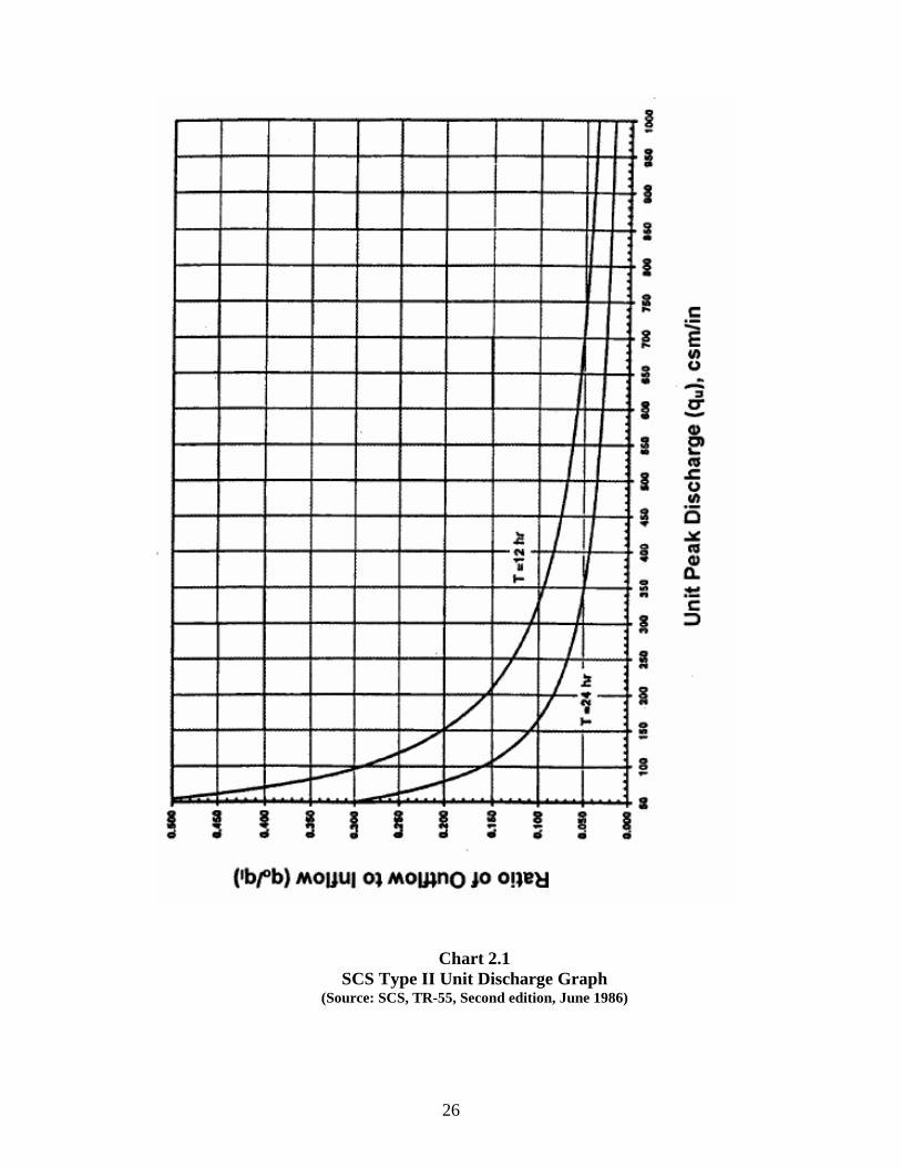
Chart 2.1 SCS Type II Unit Discharge Graph
(Source: SCS, TR-55, Second edition, June 1986)
26

Chart 2.3 Approximate Detention Basin Routing for Rainfall Types I, IA, II and III
(Source: TR-55, 1986)
27

2.3 Overbank Flood Protection (QFP) The Overbank Flood Protection criterion specifies that the post-development 2-year and 10-year (also 25-year for site 40 acres and larger), 24-hour storm peak discharge rates not exceed the pre-development (or undisturbed natural conditions) discharge rate. This is achieved through detention of runoff from these events. • The use of nonstructural site design practices that reduce the total amount of runoff will also
reduce QFP by a proportional amount.
• When the City has designated a watershed to have existing flooding problems that require increased detention and flood control requirements (See Section 1.2.1), the Q2, Q10, and QFP flows must be reduced to less than the existing flows as determined by the City.
Note: This portion of the Unified Sizing Criteria is required in ADDITION to all other
hydrologic and hydraulic analyses required by the City (i.e. 2-, 5-, 10- and 50-year events).
Determining the Overbank Flood Protection Volume (QFP) • Peak-Discharge and Hydrograph Generation: The SCS TR-55 hydrograph method will be
used to compute the peak discharge rates and runoff volumes for the all analyzed storm events. Apply the methodology for estimating the required storage volume provided below.
• Rainfall Depths: The rainfall depth of the 2-year, 24-hour storm will be 3.6 inches. The
rainfall depth of the 10-year 24-hour storm will be 5.3 inches. The rainfall depth of the 25-year, 24-hour storm will be 6.4 inches.
• Off-site Drainage Areas: Off-site drainage areas must be modeled as “present condition” for the design storm events and do not need to be included in QFP estimates, but can be routed through a structural stormwater control.
• Downstream Analysis: Downstream areas must be checked to ensure there is no peak flow
increase above pre-development conditions to the point where the site area is 10% of the total drainage to that point. See Section 3.1.4 for the full details on this method.
Estimated Volume Requirement Methodology:
1. Run typical site hydrology
2. Compute the ratio of the post-developed design storm discharge to the pre-developed discharge (qo/qi).
3. Read the volume of storage divided by the volume of runoff (vs/vr) from Chart 2.3
4. Estimate the volume of storage required for the overbank flood (Vs). Vs = vr(vs/vr) in acre-feet,
Where: vr = the post-developed volume of runoff for the selected overbank storm converted to acre-feet
5. Experience shows that multi-outlet volumes are at least 15% low so actual Q25 storage estimate is
VS = Vs *1.15
28

2.4 Extreme Flood Protection (Q100) The Extreme Flood Protection criterion specifies that all stormwater management facilities and associated grading plans and site layouts be designed to protect buildings, ponds, roads, and other permanent structures from the 100-year, 24-hour return frequency storm event, denoted Q100. This is accomplished either by: 1. Controlling Q100 through on-site or regional structural stormwater controls to maintain the
existing 100-year floodplain. This is done where residences or other structures have already been constructed within the 100-year floodplain fringe area; or
2. By designing the on-site conveyance system, site grading, and building layout to safely pass Q100 without impacting buildings, ponds, roads, or other permanent structures and allowing it to discharge into a receiving water.
Note: Flows can be conveyed without retention or detention to a receiving floodplain if it can be shown that the floodplain is sufficiently sized to account for extreme flow increases from the site without causing damage; or
3. When the City has designated a watershed to have existing flooding problems that require increased detention and flood control requirements (See Section 3.2.1), the Q100 must be reduced to less than the existing 100-year flows as determined by the City.
Local flood protection (levees, floodwalls, flood proofing, etc.) and/or channel enlargements may be offered as a substitution as appropriate, as long as adequate conveyance and structural safety is ensured through the measure used, and stream environmental integrity is adequately maintained. The City reserves the right to reject such substitutions. Determining the Extreme Flood Protection Criteria (Q100) • Peak-Discharge and Hydrograph Generation: The SCS TR-55 hydrograph method will be
used to compute the peak discharge rate and runoff for the 100-year, 24-hour storm. Apply the methodology for estimating the required storage volume provided below
• Rainfall Depths: The rainfall depth of the 100-year, 24-hour storm will be 8.3 inches.
• Off-site Drainage Areas: Off-site drainage areas must be modeled as “full build-out condition” for the 100-year storm event to ensure safe passage of future flows.
• Downstream Analysis: If Q100 is being detained, downstream areas must be checked to ensure there is no peak flow increase above pre-development conditions to the point where the site area is 10% of the total drainage to that point. See Section 3.1.4 for more details on how to properly perform a Downstream Analysis.
29

Estimated Volume Requirement Methodology:
1. Run typical site hydrology
2. Compute the ratio of the post-developed 100-year discharge to the pre-developed discharge (qo/qi).
3. Read the volume of storage divided by the volume of runoff (vs/vr) from Chart 2.3
4. Estimate the volume of storage required for the overbank flood (Vs).
Vs = vr(vs/vr) in acre-feet,
Where: vr = the post-developed volume of runoff for the selected overbank storm converted to acre-feet
5. Experience shows that multi-outlet volumes are at least 15% low so actual Q100 storage estimate is
VS = Vs *1.15
2.5 Water Quality Volume Peak Flow Calculation The peak rate of discharge for the water quality design storm (Qwq) is needed for the sizing of off-line diversion structures, such as for sand filters, bioretention, grass filter strips, grassed swales, and infiltration trenches. The following procedure can be used to estimate peak discharges for small storm events. It relies on the Water Quality Volume and the simplified peak flow estimating method above. A brief description of the calculation procedure is presented below.
1. Using WQv, a corresponding Curve Number (CN) is computed utilizing the following
equation: CN = 1000/[10 + 5P +10Qwv - 10(Qwv² + 1.25 QwvP)½]
Where, P = rainfall, in inches (use 1.2 inches for the Water Quality Storm) Qwv = Depth of Water Quality Volume is expressed in inches (1.2Rv)
Rv = 0.05 + 0.009(I) where:
I is entered as percent impervious cover (i.e. I = 30 for 30% impervious cover)
2. Once a CN is computed, the time of concentration (tc) is computed (based on SCS methodology).
30

3. Using the computed CN, time of concentration (Tc) and drainage area (A), in acres; the peak discharge (Qwq) for the water quality storm event is computed using a slight modification of the Simplified SCS Peak Runoff Rate Estimation technique, using Type II rainfall distribution:
• Read initial abstraction (Ia), compute Ia/P • Read the unit peak discharge (qu) for appropriate Tc • Using WQv, compute the peak discharge (Qwq)
Qwq = qu * A * Qwv
where Qwq = the water quality peak discharge (cfs)
qu = the unit peak discharge (cfs/mi²/inch) A = drainage area (mi2) Qwv = Depth of Water Quality Volume, in inches (1.2Rv)
31

Chapter 3 – Best Management Practices (BMPs)
3.1 Water Quantity Control Requirements
3.1.1 General Requirements Water quantity control is an integral component of overall stormwater management. Its purpose is to negate the effects of stormwater runoff associate with land use changes due to development during storm events. The following design criteria are established for water quantity control, and when applied properly will meet or exceed the requirements of SCDHEC Regulation 72-300. 1. Post-development peak discharge rates shall not exceed pre-development peak discharge
rates for the 2, and 10-year frequency 24-hour duration storm events. For developments 40 acres and larger, post-development peak discharge rates shall not exceed pre-development peak discharge rates for the 25-year frequency 24-hour duration storm event. The same hydrologic procedures shall be used in determining both the pre-development and post-development peak flow rates.
2. Post-development discharge velocities shall be reduced to provide non-erosive flow velocities from structures, channels or other control measures, or equal the pre-development 10-year 24-hour storm event flow velocities, whichever is less.
3. For post construction, the detention volume from all controls shall be drained from the structure within 72 hours. During construction, detention volumes can be temporarily stored to allow settling of particles. Upon project finalization pond elevations must be per the approved plans.
5. In addition to being allowed for water quality purposes, infiltration devices shall be required on those sites which do not currently discharge stormwater runoff or have no existing outlet. In such cases, in the post-development condition, devices shall be designed to infiltrate the runoff volume equivalent to the 5-year storm event. For evaluating storm events with a return interval greater than 5 years, the discharge rate from the site shall be limited to (not exceed) that of a site of equivalent size and slope with a SCS Curve Number equal to 39. See Section 5.2.6.L.v for more information, as well as Section 3.2.5 of the GSMM, for detailed selection, design, performance and operation & maintenance details on infiltration basins.
Note: An alternative design for infiltration basins can be found in Appendix O.
6. Watersheds with documented water quantity problems may have more stringent or modified design criteria determined by the SWD or as dictated by State and Federal Regulations. Some examples of variable criteria include but are not limited to:
a. Post-development discharge volumes from the entire development area not exceeding pre-development discharge volumes for storm frequencies smaller than the 2-year storm event,
b. Reduction of peak flow rates below pre-development levels,
c. Downstream channel, culvert, or property improvements.
7. Water quantity/volume waivers may be granted on a case-by-case basis. Final approval of a waiver request will be given at the discretion of the SWD. A water quantity/volume
32

waiver does not excuse water quality considerations. A project may be eligible for a waiver from the stormwater management requirements for water quantity/volume control if the applicant can justly verify the following items;
a. The proposed project’s peak flow rate or volume control for stormwater management would not create, aggravate, or accelerate downstream flooding or cause a detrimental impact to the downstream ecosystem, the receiving storm water system, or downstream property.
b. The design engineer shall sign the following statement, “The increased flows will not have a significant adverse impact on the downstream and adjacent properties”.
c. Calculations shall be provided that demonstrate the site has addressed the Unified Stormwater Sizing Criteria, including the Water Quality (WQv) and Channel Protection (CPv) volumes, to the maximum extent practical, or to the level specific by the SWD.
• It is recommended that a designer consult with the SWD at the earlier conceptual stages of a project to discuss water quality performance requirements for sites that may be more challenging.
8. An analysis shall be required for all development sites disturbing more than 2 acres to determine the impacts on downstream areas based on the 10-and 100-year 24-hour storm events unless a waiver or variance is granted. Downstream analysis shall determine whether the design storm events of interest cause or increase flooding, pollution, or erosion impacts to downstream properties, road crossings, and others areas as directed by the SWD. Applications for permit coverage must discuss this impact, the degree of the impact, and potential solutions. Analysis criteria shall include, but not be limited to:
a. Existing land use curve numbers shall be used for developed areas outside of the project area.
b. The weighted curve number for the developed portion of the site shall be used for all undeveloped upstream areas.
c. Flows must be routed using an accepted hydrologic and hydraulic method.
d. Hydraulic step-backwater calculations (Corps of Engineer’s HEC-2 or HEC-RAS models or equivalent) may be required by the SWD based on several factors, such as the severity of potential impact and location of project.
e. The discussions must include the severity of impact on any upstream and proposed storm water quantity or quality structure.
• If the downstream analysis determines that the development of a particular site does contribute to flooding, pollution, or erosion problems, then appropriate controls shall be implemented:
9. All quantity controls that are also used for water quality control shall have a forebay, mirco-pool, screening vault, or skimmer/debris deflector for removal of debris and coarse sediments. The benefit of the forebay is that it inhibits the main pond from filling up with large particles, therefore allowing the main pond to maintain its original design volume.
10. Documentation on the design, installation, and maintenance of stormwater quantity facilities can be found in Sections 3.2-3.4 of the GSMM.
33

3.1.2 Accepted Quantity Controls Detention structural controls are used for providing water quantity control and are typically used downstream of other minor structural controls. These structures are designed to provide channel protection, overbank flood protection, and protection against adverse downstream impacts that are related to the increase in peak flow rates and flow volumes from land disturbing activities. Detention structural stormwater controls accepted by SWD are shown in Table 3.1. Table 3.1: Accepted quantity controls
General Structural Control Description
Dry Detention/Dry Extended Basins
Dry detention basins and dry extended detention basins are surface storage facilities intended to provide temporary storage of stormwater runoff and releasing it at a designed flow rate to reduce downstream water quantity impacts. These structures are designed to completely drain to a dry condition within 72 hours.
Wet Storm Water Detention Basins • Wet Pond • Wet Extended Detention Pond • Micropool Extended Detention Pond • Multiple Pond System
Wet detention basins are constructed stormwater basins that have a permanent pool or micropool of water. Runoff from each rain event is detained above the permanent pool and released at a designed flow rate to reduce downstream water quantity impacts. Permanent pool depths must be ≥ 4 feet to reduce mosquito breeding.
Multi-purpose Detention Areas
Multi-purpose detention areas are used for one or more specific activities such as parking areas and rooftops. These areas are used to provide temporary storage of runoff. Some of the multi-purpose area such as infiltration trenches or bio-retention areas may also be used for water quality purposes.
Underground Detention
Underground detention is used as an alternative to surface dry-detention basins. They are used in areas that are space-limited where there is not enough adequate land to provide the required detention volume. The underground storage utilizes tanks, vaults, and buried pipes to supply the required storage volume.
Infiltration Basins
Infiltration basins are used to remove runoff from the flow path into the ground. They are used in areas that currently do not discharge stormwater or create runoff only during large storm events.
3.1.3 Design Procedures This section provides the general procedures for the design of stormwater quantity structures. The following items shall be required for the design of these structures and routing flows through them: 1. Compute the inflow hydrograph for the structure for the 2, 10, 25, 50 and 100-year 24-
hour storm events for both the existing and proposed conditions. From this, determine peak flow rates for each storm.
2. Compute a stage-storage relationship for the proposed structure. A stage storage-curve defines the relationship between the depth of water and storage volume within the detention facility. Stage-storage and stage-discharge calculations must be included in the engineering calculations.
34

3. Compute stage-discharge relationship of the outlet control structure(s). A stage-
discharge curve defines the flow capacity of a structure at a given stage or elevation. Also compute outlet barrel capacity and discharge velocity for energy dissipation design.
4. Perform routing calculations for the 2, 10, 25, 50 and 100-year storm events.
5. The peak discharge rate from the pond must be less than or equal to the peak discharge rate for the pre-development conditions for the 2 and 10-year storm events (also 25-year storm event for developments 40 acres and larger), unless the SWD allows a tolerance for peak flow matching. Finally, check to make sure the discharge hydrograph from the 100-year storm event provides a minimum of 1-foot of freeboard with the banks of the facility.
6. Evaluate the control structure outlet flow velocity and provide velocity control and channel stabilization. Drawings and details must be provided for outlet structures and basin.
7. Concentrated flow from any discharge point shall be returned to the overland flow condition.
3.1.4 Downstream Hydrologic Assessment The purpose of the overbank flood protection and extreme flood protection criteria is to protect downstream properties from flood increases due to upstream development. These criteria require the designer to control peak flow at the outlet of a site such that post-development peak discharge equals pre-development peak discharge. The reasons for this have to do with (1) the timing of the flow peaks, and (2) the total increase in volume of runoff. Further, due to a site’s location within a watershed, there may be very little reason for requiring overbank flood control from a particular site. This section outlines the required procedure, as part of a developer's stormwater management site plan, which is detailed in Section 2.1.9 of the GSMM. The Ten-Percent Rule: Based on studies and results for a large number of sites, a site’s zone of influence is considered to be the point where the drainage area controlled by the detention or storage facility comprises 10% of the total drainage area. For example, if the structural control drains 10 acres, the zone of influence ends at the point where the total drainage area is 100 acres or greater. However, some sites may require that the “zone of influence” be extended further downstream. Typical steps in the application of the ten-percent rule are: 1. Determine the target peak flow for the site for predevelopment conditions.
2. Using a topographic map determine the lower limit of the zone of influence (aka “10% point”).
3. Using a hydrologic model determine the pre-development peak flows and timing of those peaks at each tributary junction beginning at the pond outlet and ending at the next tributary junction beyond the 10% point.
35

4. Change the land use on the site to post-development and rerun the model.
• If the undetained post-development peak flow rates are unchanged at the “10% point”, when compared the pre-development model, the lower limit of the zone of influence has been affirmed.
• If the undetained post-development peak flow rates have increased at the “10% point” when compared the pre-development model, the lower limit of the zone of influence must be extended further downstream until there is no change in flow.
5. Design the structural control facility such that the overbank flood protection (25-year) post-development flow does not increase the peak flows at the outlet and the determined tributary junctions.
Even if the overbank flood protection requirement is eliminated, the water quality treatment (WQv), channel protection (CPv), and extreme flood protection (Q100) criteria will still need to be addressed.
For a detailed example, see Section 2.1.9 of the GSMM.
3.1.5 Routing with WQv Removed When off-line structural controls such as bioretention areas, sand filters and infiltration trenches capture and remove the water quality volume (WQv), downstream structural controls do not have to account for this volume during design. That is, the WQv may be subtracted from the total volume that would otherwise need to be routed through the downstream structural controls. From a calculation standpoint this would amount to removing the initial WQv from the beginning of the runoff hydrograph – thus creating a “notch” in the runoff hydrograph. Since most commercially available hydrologic modeling packages cannot handle this type of action, the following method has been created to facilitate removal from the runoff hydrograph of approximately the WQv: • Enter the horizontal axis on Chart 3.1 with the impervious percentage of the watershed and
read upward to the predominant soil type (interpolation between curves is permitted)
• Read left to the factor
• Multiply the curve number for the sub-watershed that includes the water quality basin by this factor – this provides a smaller curve number
The difference in curve number will generate a runoff hydrograph that has a volume less than the original volume by an amount approximately equal to the WQv. Notes:
1. This method should be used only for bioretention areas, filter facilities and infiltration trenches where the drawdown time is ≥ 24 hours.
2. This method can only be applied to catchments with a homogenous soil class (i.e. A, B, C, D), or are dominated significantly by a single soil class.
3. This method also assumed that 100% of the required WQv for the catchment area being analyzed is stored in upland BMPs
36

CN
Mul
tiplie
r
0.990
0.980
0.970
0.960
0.950
C&D Soils
B Soils
0.940 A Soils
0.930
0.920
0.910
0.900
0.1 0.2 0.3 0.4 0.5 0.6 0.7 0.8 0.9 1
% Impervious
Chart 3.1 - Curve Number Adjustment Factor
Example A site design employs an infiltration trench for the WQv and has a curve number of 72, is B type soil, and has an impervious percentage of 60%, the factor from Chart 3.1 is 0.92. The curve number to be used in calculation of a runoff hydrograph for the quantity controls would be: (72*0.92) = 66
3.2 Accepted Water Quality BMPs In selecting a BMP(s), it is most important to know what pollutants need to be treated to meet water quality goals. With proper planning, installation, and maintenance, BMPs are expected to reduce pollutant loads to receiving waters, reduce erosion, and provide health and safety benefits. Structural stormwater controls (aka BMPs) are constructed stormwater management facilities designed to treat stormwater runoff and/or mitigate the effects of increased stormwater runoff peak rate, volume, and velocity due to urbanization.
37

This Manual allows for a number of structural stormwater controls for meeting unified stormwater sizing criteria. The recommended controls are divided into three categories: general application, limited application, and detention structural controls. These categories of BMPs have varying abilities to address downstream channel protection (CPv), overbank flood protection (Q25) and/or extreme flood protection (Q100).
3.2.1 General Application Controls General application structural controls are recommended for use with a wide variety of land uses and development types. These structural controls have a demonstrated ability to effectively treat the Water Quality Volume (WQv) and are presumed to be able to remove 80% of the total annual average TSS load in typical post-development urban runoff when designed, constructed and maintained in accordance with recommended specifications. The allowable types of general application controls are summarized below. Detailed descriptions of each structural control along with design criteria and procedures are provided in Section 3.2 of the GSMM. Table 3.2 lists and briefly describes the general application structural stormwater control practices. These structural controls are recommended for use in a wide variety of applications. A detailed discussion of each of the general application controls, as well as design criteria and procedures can be found in Section 3.2 of the GSMM.
Table 3.2 General Application Structural Controls
Structural Control
Description
Stormwater Ponds
• Wet • Wet Extended Detention • Micropool Extended
Detention • Multiple Pond Systems
Wet detention basins are constructed stormwater basins that have a permanent pool or micropool of water. Runoff from each rain event is detained above the permanent pool and released at a designed flow rate to reduce downstream water quantity impacts. Permanent pool depths must be ≥ 4 feet to reduce mosquito breeding.
Bioretention Areas Bioretention areas are shallow stormwater basins or landscaped
areas which utilize engineered soils and vegetation to capture and treat stormwater runoff. Runoff may be returned to the conveyance system, via underdrain, or allowed to partially infiltrate into the soil.
Infiltration Trench/Basin
An infiltration trench is an excavated trench filled with stone aggregate used to capture and allow infiltration of stormwater runoff into the surrounding soils through the bottom and sides of the trench. An infiltration basin allows infiltration of stormwater runoff into the surrounding soils through the bottom and sides of the trench.
38

Table 3.2 General Application Structural Controls
Structural Control
Description
Enhanced Swales
• Dry Swale • Wet Swale/Wetland
Channel
Enhanced swales are vegetated open channels that are explicitly designed and constructed to capture and treat stormwater runoff within dry or wet cells formed by check dams or other means.
3.2.2 Limited Application Controls
Table 3.3 lists the limited application structural stormwater control practices, along with the rationale for limited use. These structural controls are recommended for use with particular land uses and densities, to meet certain water quality requirements, for limited usage on larger projects, or as part of a stormwater treatment train. A detailed discussion of each of the limited application controls, as well as design criteria and procedures can be found in Section 3.3 of the GSMM.
Table 3.3 Limited Application Structural Controls
Structural Control
Description and Rationale for Limited Use
Biofilters
• Filter Strip • Grass Channel
Both filter strips and grass channels provide “biofiltering” of stormwater runoff as it flows across the grass surface. However, by themselves these controls cannot meet the performance goal. Consequently, both filter strips and grass channels should only be used as pretreatment measure or as part of a treatment train approach. They are also acceptable for use as a site design credit (see Chapter 4).
Hydrodynamic Devices
• Gravity (Oil-Grit) Separator
Hydrodynamic controls use the movement of stormwater runoff through a specially designed structure to remove target pollutants. They are typically used on smaller impervious commercial sites and urban hotspots. These controls typically do not meet the 80% TSS removal performance goal and therefore should only be used as a pretreatment measure and as part of a treatment train approach.
Porous Surfaces
• Porous Concrete • Porous Asphalt • Modular Porous Paver
Systems
Porous surfaces are permeable pavement surfaces with an underlying stone reservoir to temporarily store surface runoff before it infiltrates into the subsoil. Porous concrete is the term for a mixture of course aggregate, portland cement and water that allows for rapid infiltration of water. Modular porous paver systems consist of open void paver units laid on a gravel subgrade. Both porous concrete and porous paver systems provide water quality and quantity benefits, but have high workmanship and maintenance requirements, as well as high failure rates. Note: Porous asphalt surfaces have a higher tendency to be clogged by clays, silts and oils resulting in a potentially high maintenance burden to maintain the effectiveness of this structural control. Further, summer heat in South Carolina can cause the asphalt to melt, destroying the porous properties of the surface. Therefore, the specific application of this BMP must be reviewed for both sediment and heat issues, as well as the traffic load that it is intended to carry, before allowing the application of this BMP.
39

Table 3.3 Limited Application Structural Controls (Cont.)
Structural Control
Description and Rationale for Limited Use
• Media Filter Inserts
Media filter inserts, such as catch basin inserts and filter systems, are easily clogged and require a high degree of regular maintenance and replacement to achieve the intended water quality treatment performance and should not be used for areas of new development or redevelopment. These structural controls may serve a potential use in stormwater retrofitting. Before using this BMP, the designer must justify the anticipated performance for the constituent of concern, and receive approval from the City before included this BMP in any designs or construction activities.
Proprietary Systems
• Commercial Stormwater Controls
Proprietary controls are manufactured structural control systems available from commercial vendors designed to treat stormwater runoff and/or provide water quantity control. Proprietary systems often can be used on small sites and in space-limited areas, as well as in pretreatment applications. However, proprietary systems are often more costly than other alternatives, may have high maintenance requirements, and often lack adequate independent performance data, particularly for use in Georgia conditions.
3.2.3 Detention Structural Controls
Table 3.4 lists the detention structural stormwater control practices. These structural controls are recommended only for providing water quantity control, i.e. channel protection, overbank flood protection and/or extreme flood protection in a stormwater treatment train. A detailed discussion of each of the detention controls, as well as design criteria and procedures can be found in Section 3.4 of the GSMM. Due to the potential for pollutant resuspension and outlet clogging, detention structural controls are not intended to treat stormwater runoff and should be used downstream of other water quality structural control in a treatment train (forebay, micro-pool, filter strip, etc.)
40

3.2.4 Not Recommended Structural Controls
The following structural controls in Table 3.5 are not recommended for use in the City of Columbia to meet stormwater management objectives, as they fail to demonstrate an ability to meet the majority of the water quality treatment goals and/or present difficulties in operation and maintenance.
Table 3.5 Not Recommended Structural Controls
Structural Control
Rationale for Lack of Recommendation
Stormwater Wetlands
• Shallow Wetland • Extended Detention
Shallow Wetland
Stormwater wetlands consist of a combination of shallow marsh areas, open water and semi-wet areas above the permanent water surface. In order to keep them alive and functioning, proper hydroperiods must be maintained. Creating a wetland near development is likely to have difficulty in maintaining the hydrperiod due to the lack of baseflow and distance from the water table.
Table 3.4 Detention Structural Controls
Structural Control
Description
Dry Detention / Dry Extended Detention Basins
Dry detention basins and dry extended detention (ED) basins are surface facilities intended to provide for the temporary storage of stormwater runoff to reduce downstream water quantity impacts.
Multi-Purpose Detention
Areas
Multi-purpose detention areas are site areas used for one or more specific activities, such as parking lots and rooftops, which are also designed for the temporary storage of runoff.
Underground Detention
Underground detention tanks and vaults are an alternative to surface dry detention for space-limited areas where there is not adequate land for a dry detention basin or multi-purpose detention area.
41

3.2.5 Using Other or New Structural Stormwater Controls Innovative technologies may be allowed, providing there is sufficient documentation as to their effectiveness and reliability. The City will not allow any such technologies without independently derived information concerning performance, maintenance, application requirements and limitations. More specifically, new structural stormwater control designs will not be accepted for inclusion in the Manual until independent pollutant removal performance monitoring data determine that the practice can meet the TSS and other selected pollutant concentration removal targets, and that the structural control conforms with local and/or State criteria for treatment, maintenance, and environmental impact.
3.2.6 Structural Stormwater Control Pollutant Removal Capabilities
General and limited application structural stormwater controls are intended to provide water quality treatment for stormwater runoff. Though each of these structural controls provides pollutant removal capabilities, the relative capabilities vary between structural control practices and for different pollutant types. Pollutant removal capabilities for a given structural stormwater control practice are based on a number of factors including the physical, chemical and/or biological processes that take place in the structural control and the design and sizing of the facility. In addition, pollutant removal efficiencies for the same structural control type and facility design can vary widely depending on the tributary land use and area, incoming pollutant concentration, rainfall pattern, time of year, maintenance frequency and numerous other factors. To assist the designer in evaluating the relative pollutant removal performance of the various structural control options, Appendix J provides design removal efficiencies for each of the general and limited application control practices. It should be noted that these values are conservative average pollutant reduction percentages for design purposes derived from sampling data, modeling and professional judgment. A structural control design may be capable of exceeding these performances, however the values in the table are minimum reasonable values that can be assumed to be achieved when the structural control is sized, designed, constructed and maintained in accordance with recommended specifications in this Manual. Where the pollutant removal capabilities of an individual structural stormwater control are not deemed sufficient for a given site application, additional controls may be used in series in a “treatment train” approach. More detail on using structural stormwater controls in series is provided in Section 3.2.8. For additional information and data on the range of pollutant removal capabilities for various structural stormwater controls, the reader is referred to the National Pollutant Removal Performance Database (2nd Edition) available at: www.cwp.org www.bmpdatabase.org
42

3.2.7 Structural Stormwater Control Selection General Application Control Screening Process Outlined below is a screening process for General Application structural stormwater controls. This process is intended to assist the site designer and design engineer in the selection of the most appropriate structural controls for a development site, and provides guidance on factors to consider in their location. In general the following four criteria must be evaluated in order to select the appropriate structural control(s) or group of controls for a development:
• Stormwater Treatment Suitability • Water Quality Performance • Site Applicability • Implementation Considerations
In addition, for a given site, the following factors must be considered and any specific design criteria or restrictions need to be evaluated:
• Physiographic Factors • Soils • Special Watershed or Stream Considerations
Finally, environmental regulations that may influence the location of a structural control on site, or may require a permit, need to be considered.
Section 3.1.3 of the GSMM provides a detailed selection process for comparing and evaluating various general application structural stormwater controls using two screening matrices and a list of location and permitting factors. Those tools can assist the design engineer in selecting the subset of structural controls that will meet the stormwater management and design objectives for a development site or project.
3.2.8 Using Structural Stormwater Controls in Series The following subsections provide a general description of how BMPs in series can be used to meet water quality goals, and the appropriate manner in which to calculate their cumulative effect on removing pollutants.
3.2.8.1 General Methodology Stormwater Treatment Trains The minimum stormwater management standards are an integrated planning and design approach, sometimes called a stormwater “treatment train”. A treatment train consists of all the design concepts and nonstructural and structural controls that work to attain water quality and quantity goals. This is illustrated in Figure 3.1.
43

E
Figure 3.1: Generalized Stormwater Treatment Train
Runoff & Load
Generation
Pretreatment
Primary
Treatment and/or Quantity Control
Runoff and Load Generation – The initial part of the “train” is located at the source of runoff and pollutant load generation, and consists of better site design and pollution prevention practices that reduce runoff and stormwater pollutants. Pretreatment – The next step in the treatment train consists of pretreatment measures. These measures typically do not provide sufficient pollutant removal to meet the 80% TSS reduction goal, but do provide calculable water quality benefits that may be applied towards meeting the WQv treatment requirement. Primary Treatment and/or Quantity Control – The last step is primary water quality treatment and/or quantity (channel protection, overbank flood protection, and/or extreme flood protection) control. Many combinations of structural controls in series may exist for a site. Figure 3.2 provides a number of hypothetical examples of how the unified stormwater sizing criteria may be addressed by using structural stormwater controls.
Figure 3.2 Examples of Structural Controls Used in Series
Water Quality
Channel Protection
Overbank Flooding
Extreme Flood
A Stormwater Ponds / Stormwater Wetlands
B Other GA Control Extended Det. Detention
C Site Design Credits Extended Det. Detention Floodplain Mgmt.
D LA Control GA Control Extended Det. Detention
Site Design Credits LA Control waived Detention
Floodplain Mgmt.
Referring to Figure 3.2 by line letter:
44

A. Two general application (GA) structural controls, stormwater ponds and stormwater wetlands, can be used to meet all of the unified stormwater sizing criteria in a single facility. B. The other general application structural controls (bioretention, sand filters, infiltration trench and enhanced swale) are typically used in combination with detention controls to meet the unified stormwater sizing criteria. The detention facilities are located downstream from the water quality controls either on-site or combined into a regional or neighborhood facility. C. Line C indicates the condition where an environmentally sensitive large lot subdivision has been developed that can be designed so as to waive the water quality treatment requirement altogether. However, detention controls may still be required for downstream channel protection, overbank flood protection and extreme flood protection. D. Where a limited application (LA) structural control does not meet the 80% TSS removal criteria, another downstream structural control must be added. For example, urban hotspot land may be fit or retrofit with devices adjacent to parking or service areas designed to remove petroleum hydrocarbons. These devices may also serve as pre-treatment devices removing the coarser fraction of sediment. One or more downstream structural controls is then used to meet the full 80% TSS removal goal, and well as water quantity control. E. In line E site design credits have been employed to partially reduce the water quality volume requirement. In this case, for a smaller site, a well designed and tested Limited Application structural control provides adequate TSS removal while a dry detention pond handles the overbank flooding criteria. For this location, direct discharge to a large stream and local downstream floodplain management practices have eliminated the need for channel protection volume and extreme flood protection structural controls on site.
3.2.8.2 Calculation of Pollutant Removal for Structural Controls in Series For two or more structural stormwater controls used in combination, it is often important to have an estimate of the pollutant removal efficiency of the treatment train. Pollutant removal rates for structural controls in series are not additive. For pollutants in particulate form, the actual removal rate (expressed in terms of percentage of pollution removed) varies directly with the pollution concentration and sediment size distribution of runoff entering a facility. For example, a stormwater pond facility will have a much higher pollutant removal percentage for very turbid runoff than for clearer water. When two stormwater ponds are placed in series, the second pond will treat an incoming particulate pollutant load very different from the first pond. The upstream pond captures the easily removed larger sediment sizes, passing on an outflow with a lower concentration of TSS but with a higher proportion of finer particle sizes. Hence, the removal capability of the second pond for TSS is considerably less than the first pond. Recent findings suggest that the second pond in series can provide as little as half the removal efficiency of the upstream pond. To estimate the pollutant removal rate of structural controls in series, a method is used in which the removal efficiency of a downstream structural control is reduced to account for the pollutant removal of the upstream control(s). The following steps are used to determine the pollutant removal:
• For each drainage area list the structural controls in order, upstream to downstream, along with
their expected average pollutant removal rates from Appendix J for the pollutants of concern.
45

• For cases where a limited application control is sited upstream from a general application
control in the treatment train, the downstream general application structural control is given full credit for removal of pollutants.
• For any general application structural control located downstream from another general application control or a limited application structural control that has TSS removal rates equivalent to 80%, the designer should use half (i.e. 40% removal rate) of the normal pollutant removal rate for the second control in series. The reason for reducing the downstream BMP removal rate to half of its normal rate is that: o The larger particles, which are easier to trap, were removed by the upstream BMP
o The remaining particles, which are smaller and harder to trap, remain for the downstream BMP and thereby reduce its effective removal rate
• For a general application structural control located downstream from a limited application structural control that cannot achieve the 80% TSS reduction goal the designer should use 75% of the normal pollutant removal rate for the second control in series. Example:
TSS is the pollutant of concern and a stormwater pond is designed at the site outlet. A second stormwater pond is located downstream from the first one in series. If each pond has a normal removal rate of 80%, what is the total TSS removal rate? The following information is given:
o Control 1 (Stormwater Pond 1) = 80% TSS removal (use 1.0 x design removal rate) o Control 2 (Stormwater Pond 2) = 40% TSS removal (use 0.5 x design removal rate)
Then applying the controls in order and working in terms of “units” of TSS starting at 100 units:
For Control 1: 100 units of TSS * 80% removal rate
o 80 units removed; 20 units remaining For Control 2: 20 units of TSS * 40% removal rate
o 8 units removed; 12 units remaining
For the treatment train in total: o We started with 100 units; 12 units remain o 88 units were removed = 88% removal rate
3.2.9 On-Line Versus Off-Line Structural Controls Structural stormwater controls are designed to be either “on-line” or “off-line.” On-line facilities are designed to receive, but not necessarily control or treat, the entire runoff volume up to the Q25 or Q100 event. On-line structural controls must be able to handle the entire range of storm flows. Off-line facilities on the other hand are designed to receive only a specified flow rate through the use of a flow regulator (i.e. diversion structure, flow splitter, etc). Flow regulators are typically used to divert the water quality volume (WQv) to an off-line structural control sized and designed to treat and control the WQv. After the design runoff flow has been treated and/or controlled it is returned to the conveyance system. Figure 3.3 provides an example of an off-line sand filter and an off-line enhanced dry swale.
46

Figure 3.3 Example of On-Line versus Off-Line Structural Controls (Source: CWP, 1996)
47

Flow regulation to off-line structural stormwater controls can be achieved by either: • Diverting the water quality volume or other specific maximum flow rate to an off-line
structural stormwater control, or • Bypassing flows in excess of the design flow rate The peak water quality flow rate (Qwq) can be calculated using the procedure found in Chapter 2. Flow regulators can be flow splitter devices, diversion structures, or overflow structures (See Figures 3.4-3.6).
Figure 3.4 Pipe Interceptor Diversion Structure (Source: City of Sacramento, 2000)
48

Figure 3.5 Surface Channel Diversion Structure (Source: City of Sacramento, 2000)
Figure 3.6 Outlet Flow Regulator (Source: City of Sacramento, 2000)
49

Chapter 4 – Site Design Stormwater Credits
A set of stormwater “credits” has been developed to provide developers and site designers an incentive to implement better site design practices that can reduce the volume of stormwater runoff and minimize the pollutant loads from a site. The credit system directly translates into cost savings to the developer by allowing for a reduction in the water quality treatment volume (WQv). This also reduces the size of structural stormwater control and conveyance facilities for events greater than the water quality treatment (WQv) event.
The better site design practices that provide stormwater credits are listed in Table 4.1. Site-specific conditions will determine the applicability of each credit. For example, stream buffer credits cannot be taken on upland sites that do not contain perennial or intermittent streams. Note: better site design practices and techniques that reduce the overall impervious area on a site already implicitly reduce the total amount of stormwater runoff generated by a site (and thus reduce WQv) and are not further credited under this system.
Table 4.1 Summary of Better Site Design Practices Providing Stormwater Volume Credits
Practice Description Natural area conservation
Undisturbed natural areas are conserved on a site, thereby retaining their pre-development hydrologic and water quality characteristics.
Stream buffers
Stormwater runoff is treated by directing sheet flow runoff through a naturally vegetated or forested buffer as overland flow.
Use of vegetated channels
Vegetated channels are used to provide stormwater treatment.
Overland flow filtration/infiltration zones
Overland flow filtration/infiltration zones are incorporated into the site design to receive runoff from rooftops and other small impervious areas.
For each potential credit, there is a minimum set of criteria and requirements (e.g., flow length, contributing area, etc.) which identify the conditions or circumstances under which the credit may be applied. Site designers are encouraged to utilize as many credits as they can on a site. Greater reductions in stormwater storage volumes can be achieved when many credits are combined (e.g., disconnecting rooftops and protecting natural conservation areas). However, credits cannot be claimed twice for an identical area of the site (e.g. claiming credit for stream buffers and conservation area over the same site area).
Note: Due to local safety codes, soil conditions, and topography, some of these site design credits may be restricted. Designers are encouraged to consult with the City to ensure if and when a credit is applicable and to determine restrictions on non-structural strategies.
50

4.1 Stormwater Credits and the Site Planning Process
During the site planning process (see Section 1.5 of the GSMM) the integration of site design credits can be integrated with this process as shown in Table 4.2.
Table 4.2 Integration of Site Design Credits with Site Development Process
Site Development Ph
Site Design Credit Activity Feasibility Study
• Determine stormwater management requirements • Perform site reconnaissance to identify potential areas for and
types of credits
Site Analysis • Identify and delineate natural feature conservation areas
(natural areas and stream buffers) Concept Plan
• Preserve natural areas and stream buffers during site layout • Reduce impervious surface area through various
techniques • Identify locations for use of vegetated channels and
groundwater recharge • Look for areas to disconnect impervious surfaces • Document the use of site design credits.
Preliminary and Final Plan
• Perform layout and design of credit areas – integrating them into treatment trains
• Ensure unified stormwater sizing criteria are satisfied • Ensure appropriate documentation of site design credits
according to local requirements.
Construction
• Ensure protection of key areas • Ensure correct final construction of areas needed for credits
Final Inspection
• Develop maintenance requirements and documents • Ensure long term protection and maintenance • Ensure credit areas are identified on final plan and plat if
applicable
51

Site Design Credit #1: Natural Area Conservation A stormwater credit can be taken when undisturbed natural areas are conserved on a site, thereby retaining their pre-development hydrologic and water quality characteristics. Under this credit, a designer would be able to subtract conservation areas from total site area when computing water quality volume requirements and adhering to the criteria listed below. An added benefit will be that the post- development peak discharges will be smaller, and hence water quantity control volumes (CPv, Q25, and Q100) will be reduced due to lower post-development curve (CN) numbers. Rule: Subtract conservation areas from total site area when computing water quality
volume requirements. Criteria: • Conservation area cannot be disturbed during project construction
• Shall be protected by limits of disturbance clearly shown on all construction drawings
• Shall be located within an acceptable conservation easement instrument that ensures perpetual protection of the proposed area.
• The easement must clearly specify how the natural area vegetation shall be managed and boundaries will be marked
• Managed turf (e.g., playgrounds, regularly maintained open areas) is not an acceptable form of vegetation management], and shall have a minimum contiguous area requirement of 10,000 square feet
• Rv is kept constant when calculating WQv Example: Residential Subdivision
Area = 38 acres Natural Conservation Area = 7 acres Impervious Area = 13.8 acres
Rv = 0.05 + 0.009 (I) = 0.05 + 0.009 (36.3%) = 0.37 Credit:
7.0 acres in natural conservation area New drainage area = 38 – 7 = 31 acres
Before credit: WQv = (1.2)(0.37)(38)/12 = 1.40 ac-ft
With credit: WQv = (1.2)(0.37)(31)/12 = 1.15 ac-ft
(18% reduction in water quality volume)
52

Site Design Credit #2: Stream Buffers This credit can be taken when stormwater runoff is effectively treated by a stream buffer. Effective treatment constitutes treating runoff through overland flow in a naturally vegetated or forested buffer. Under the proposed credit, a designer would be able to subtract areas draining via overland flow to the buffer from total site area when computing water quality volume requirements. In addition, the volume of runoff draining to the buffer can be subtracted from the channel protection volume. The design of the stream buffer treatment system must use appropriate methods for conveying flows above the annual recurrence (1-yr storm) event, and adhere to the criteria listed below. Rule: Subtract areas draining via overland flow to the buffer from total site area when
computing water quality volume requirements. Criteria: • The minimum undisturbed buffer width shall be 50 feet, or as required by the City’s Buffer
Ordinance, whichever is greater.
• The maximum contributing length shall be 150 feet for pervious surfaces and 75 feet for impervious surfaces
• The average contributing slope shall be 3% maximum unless a flow spreader is used
• Runoff shall enter the buffer as overland sheet flow. A flow spreader can be supplied to ensure this, or if average contributing slope criteria cannot be met
• Not applicable if overland flow filtration/groundwater recharge credit is already being taken
• Buffers shall remain unmanaged other than routine debris removal
• Rv is kept constant when calculating WQv
Example: Residential Subdivision
Area = 38 acres Impervious Area = 13.8 acres Area Draining to Buffer = 5 acres
Rv = 0.05 + 0.009 (I) = 0.05 + 0.009 (36.3%) = 0.37 Credit:
5.0 acres draining to buffer New drainage area = 38 – 5 = 33 acres Before credit: WQv = (1.2)(0.37)(38)/12 = 1.40 ac-ft With credit: WQv = (1.2)(0.37)(33)/12 = 1.22 ac-ft
(13% reduction in water quality volume)
53

Site Design Credit #3: Vegetated Channels This credit may be taken when vegetated (grass) channels are used for water quality treatment. Under the proposed credit, a designer would be able to subtract the areas draining to a grass channel from total site area when computing water quality volume requirements. A vegetated channel can fully meet the water quality volume requirements for certain kinds of low-density residential development (see low impact development credit). An added benefit will be that the post-development peak discharges will likely be lower due to a longer time of concentration for the site.
This credit cannot be taken if grass channels are being used as a limited application structural stormwater control (i.e. not designed to fully meet the design methodology and criteria) towards meeting the pollutant reduction goal for WQv treatment.
Rule: Subtract the areas draining to a grass channel from total site area when computing
water quality volume requirements. Criteria: • The credit shall only be applied to moderate or low density residential land uses (3 dwelling
units per acre maximum) • The maximum flow velocity for water quality design storm shall be less than or equal to feet
per second
• The minimum residence time for the water quality storm shall be 5 minutes • The bottom width shall be a maximum of 6 feet. If a larger channel is needed use of a
compound cross section is required
• The side slopes shall be 3:1 (horizontal:vertical) or flatter
• The channel slope shall be 3 percent or less
• Rv is kept constant when calculating WQv
Example: Residential Subdivision
Area = 38 acres Impervious Area = 13.8 acres
Rv = 0.05 + 0.009 (I) = 0.05 + 0.009 (36.3%) = 0.37 Credit:
12.5 acres meet grass channel criteria New drainage area = 38 – 12.5 = 25.5 acres
Before credit: WQv = (1.2)(0.37)(38)/12 = 1.40 ac-ft
With credit: WQv = (1.2)(0.37)(25.5)/12 = 0.94 ac-ft
(33% reduction in water quality volume)
54

Site Design Credit #4: Overland Flow Filtration/Groundwater Recharge Zones This credit can be taken when “overland flow filtration/infiltration zones” are incorporated into the site design to receive runoff from small impervious areas (e.g., driveways, small parking lots, etc). This can be achieved by grading the site to promote overland vegetative filtering or infiltration areas (i.e. rain gardens). If impervious areas are adequately disconnected, they can be deducted from total site area when computing the WQv requirements. An added benefit will be that the post-development peak discharges will likely be lower due to a longer time of concentration for the site. Rule: If impervious areas are adequately disconnected (i.e. the receiving area has the
appropriate soils, surface area, length and slope to filer and/or infiltrate the calculated runoff volume for the water quality event), they can be deducted from total site area when computing the water quality volume requirements.
Criteria: • Relatively permeable soils (hydrologic soil groups A and B) must be present • Runoff shall not come from a designated hotspot • The maximum contributing impervious flow path length shall be 75 feet • Downspouts shall be 10+ feet away from impervious surface to discourage “re-connections” • The disconnection shall drain continuously through a vegetated channel, swale, or filter strip
to the property line or structural stormwater control • The length of the “disconnection” shall be equal to or greater than the contributing length • The entire vegetative “disconnection” shall be on a slope less than or equal to 3 percent • The imperviousness area to a discharge location is 5,000 square feet or less. • If draining directly to a buffer the stream buffer credit cannot also be used • Rv is kept constant when calculating WQv
Example: Site Area = 3.0
Impervious Area = 1.9 acres (or 63.3% impervious cover) “Disconnected” Impervious Area = 0.5 acres
Rv = 0.05 + 0.009 (I) = 0.05 + 0.009 (63.3%) = 0.62 Credit:
0.5 acres of surface imperviousness hydrologically disconnected New drainage area = 3 – 0.5 = 2.5 acres
Before credit: WQv = (1.2)(0.62)(3)/12 = 0.19 ac-ft With credit: WQv = (1.2)(0.62)(2.5)/12 = 0.15 ac-ft
(21% reduction in water quality volume)
55

4.2 User Fee Crediting Options
The Unified Sizing Criteria (USC) method is hydrology-based, using imperviousness as the key factor in determining the WQV and associated stormwater burden on the City. The User Fee is the City’s primary funding mechanism for managing stormwater quality associated with impervious areas. Mitigating stormwater quality impacts through the use of Better Site Design and Best Management Practices can reduce the burden on the City and will be rewarded by a reduction in the User Fee, where applicable. To calculate the User Fee Credit for Water Quality Volume Reduction, use the following method:
1. Calculate the WQV that is addressed by the site, based on the USC Methodology. 2. Convert the WQV to an area by dividing the WQV by the water quality rainfall
depth of 1.2 inches. This is the area of which water quality impacts will be fully mitigated (by infiltration and/or filtration) - this will be referred to as the WQV Impervious Reduction (IR).
3. Identify the amount of physical imperviousness that the site contains, which the User Fee would be based on – this will be referred to as the Impervious Area (IA).
4. Compare the IR and IA values, and generate a % Reduction that is applied to the fee (i.e. IR/IA = % Reduction). The % Reduction should be rounded to the nearest whole number. User fee crediting will be capped at a maximum % Reduction of 30%.
5. Multiply the % Reduction by the User Fee (based on Impervious Area) to calculate the final amount of the User Fee.
Chapter 5 – Additional BMP Requirements
5.1 Water Surface Dewatering When discharging stormwater from temporary sediment basins, sediment ponds, or other similar impoundments, utilize outlet structures that only withdraw water from near the surface of the basin or impoundment, unless infeasible. The outlet structure should be capable of conveying the flow of the 10-year, 24-hour storm event. Typically referred to as “skimmers,” water surface dewatering devices are designed to improve sediment trapping efficiency by regulating the filling and draining of a stormwater basin or pond. Since these devices float on the water surface, the skimmer orifice has a constant head that allows the basin to drain slowly at a constant rate from the water surface, where sediment concentrations are typically lowest. Sediment basins and sediment ponds must be designed to consider the specific site conditions, including soil types, drainage area, sediment generated, rainfall, runoff, and potential risk for downstream impacts. When designing a sediment basin or sediment pond, the engineer should provide appropriate supporting calculations for the skimmer. Several manufacturers of these devices offer design guidance, construction details and specifications.
56

Appendices A. Design Aids
• Calculation Worksheets -Volume Calculation Tool -BMP Sizing Tools for: Bioretention Infiltration Trench Dry Enhanced Swale Grass Filter Strip Porous Surfaces
• Standard CAD Details and Notes/Specs Bioretention
Infiltration Trench Dry Enhanced Swale Grass Filter Strip
Micropool Extended Dry Detention Pond Wet Detention Pond
B. Maintenance Schedules C. Flood Area Map
57

Appendix C: Flood Area Map
FEMA_COC areas.pdf
58