Embed Size (px)
Citation preview

STORM WATER DRAINAGE DESIGN MANUAL
Prepared for
Alpine City 20 North Main Street Alpine, Utah 84004
Prepared by
Bowen, Collins & Associates 756 East 12200 South
Draper, UT 84020
February 2010
BO W E N O L L IN S C
Consulting Engineers
& Associates, Inc.

ALPINE CITY STORM WATER DRAINAGE
DESIGN MANUAL
February 2010
STORM WATER DRAINAGE DESIGN MANUAL
BOWEN, COLLINS & ASSOCIATES ALPINE CITY i
TABLE OF CONTENTS
Page No.
Section 1 – Purpose...................................................................................... 1
Section 2 – Approval Procedure.................................................................. 2
2.1 Introduction.................................................................................. 2 2.2 Conceptual Drainage Plan ............................................................ 2 2.3 Final Drainage Plan and Report .................................................... 3
Section 3 – Design Standards and Regulations for Storm Drain Facilities 6 3.1 Design Storm ............................................................................... 6 3.1.1 Frequency........................................................................... 6 3.1.2 Depth and Intensity............................................................. 6 3.1.3 Distribution and Duration ................................................... 6 3.2 Post-Construction Peak Discharge................................................ 7 3.3 Storage Facilities.......................................................................... 7 3.4 Pipelines....................................................................................... 7 3.5 Inlets and Outlets ......................................................................... 8 3.6 Manholes and Cleanout Structures................................................ 8 3.7 Roadway Drainage ....................................................................... 8 3.8 Inlets ............................................................................................ 8 3.9 Storm Water Treatment ................................................................ 9 3.10 Culverts........................................................................................ 9 3.11 Bridges....................................................................................... 10 3.12 Open Channels ........................................................................... 10 3.13 Floodplains ................................................................................ 10
Section 4 – Rainfall-Runoff Computation Methods ................................. 11 4.1 Modeling Approach.................................................................... 11 4.2 Drainage Basin Delineation........................................................ 11 4.3 Projected Future Land Use Conditions ....................................... 11 4.4 Rational Method......................................................................... 12
4.4.1 Runoff Coefficient .......................................................... 12 4.4.2 Time of Concentration .................................................... 13 4.4.3 Rainfall Intensity ............................................................ 13
4.5 TR-55......................................................................................... 13 4.6 HEC-HMS ................................................................................. 14
4.6.1 Design Storm.................................................................. 14 4.6.2 Loss Method................................................................... 14

STORM WATER DRAINAGE DESIGN MANUAL
BOWEN, COLLINS & ASSOCIATES ALPINE CITY ii
Table of Contents (continued)
Page No.
4.6.3 Transform Method.......................................................... 14 4.6.4 Routing Method.............................................................. 15
4.7 Other Models ............................................................................. 16 4.8 Calibration ................................................................................. 16
Section 5 – Erosion Control....................................................................... 18 5.1 UPDES Permit ........................................................................... 18 5.2 Storm Water Pollution Prevention Plan ...................................... 18 5.3 Permitting Process...................................................................... 18
References .................................................................................................. 20 APPENDIX A – NOAA ATLAS 14 INFORMATION APPENDIX B – STORM DISTRIBUTIONS APPENDIX C – TR-55 INFORMATION APPENDIX D – SOIL MAP
TABLES
No. Title ................................................................................................ Page No. 3-1 Design Gutter Spread....................................................................................9 4-1 Drainage Models and Applicable Total Drainage Area................................11 4-2 Rational Method Runoff Coefficients..........................................................12 4-3 Values of Manning’s Coefficient (n) for Channels and Pipes ......................15 4-4 Range of Basin Characteristics Used to Develop Regression Equations ......17 for Small Urban Drainages 4-5 Regression Equations for Peak Flows for Small Urban Drainages ...............17

STORM WATER DRAINAGE DESIGN MANUAL
BOWEN, COLLINS & ASSOCIATES 1 ALPINE CITY
SECTION 1 PURPOSE
This manual has been prepared to document the approval process, design standards and regulations, and hydrologic and hydraulic computation methods for evaluating and designing storm drain and flood control facilities in Alpine City (City). The objective of this manual is to ensure that drainage planning and facility design for small areas and local developments within the City are consistent with the City’s Storm Drain Master Plan. All drainage projects shall conform to requirements in this Storm Water Drainage Design Manual, the City’s Storm Drain Master Plan, and shall be approved by City personnel.

STORM WATER DRAINAGE DESIGN MANUAL
BOWEN, COLLINS & ASSOCIATES 2 ALPINE CITY
SECTION 2 APPROVAL PROCEDURE
2.1 INTRODUCTION The following procedures shall be followed for evaluating the need for and designing storm water facilities. 2.2 CONCEPTUAL DRAINAGE PLAN A Conceptual Drainage Plan and Report is required for all multi-lot developments and single lot developments larger than 0.5 acres. The report shall contain the following information:
1. General description of the development, including location (township, range, section, subdivision and lot).
2. General description of property, area, existing site conditions including all
existing drainage facilities such as ditches, canals, washes, swales structures, storm drains, springs, detention and retention basins, and any proposed modifications to drainage facilities.
3. General description of off-site drainage features and characteristics upstream and
downstream of the site and any known drainage problems. 4. General description of existing and proposed on-site drainage features,
characteristics and facilities.
5. General description of the proposed facilities that will be used to manage on-site and off-site storm water runoff associated with the development.
6. General description of master planned drainage facilities and proposed drainage
features and how the development and proposed drainage facilities conform to the storm drain master plan.
7. Preliminary Drainage Calculations if required by the City Engineer. See Section
3 for design criteria.
8. Estimate of minimum depth to groundwater level on the site. One or more drawings shall also be submitted. The drawing(s) shall include:
1. Existing and proposed property lines. 2. Existing and proposed topography (2-foot maximum contour interval) extending
at least 100 feet beyond the site.

STORM WATER DRAINAGE DESIGN MANUAL
BOWEN, COLLINS & ASSOCIATES 3 ALPINE CITY
3. Existing and proposed streets, easements, and rights-of-way. 4. Existing drainage and irrigation facilities. 5. FEMA floodplain and floodway.
6. Required setbacks for structures from the center line of streams and washes, if
applicable. 7. Drainage basin boundaries and subbasin boundaries on a topographical map. 8. Existing flow patterns and paths. 9. Proposed flow patterns and paths. 10. Location of proposed drainage facilities including: storm drain pipes, inlets,
manholes, cleanouts, swales, channels, and retention and detention basins. 11. Location of drainage easements required.
12. Other relevant drainage features 13. Scale, north arrow, legend, title block showing project name, date, preparers
name, seal and signature. The Conceptual Drainage Plan shall be submitted to the City for review and approval prior to the development of the Final Drainage Design Plan and Report. 2.3 FINAL DRAINAGE PLAN AND REPORT A final Drainage Plan and Report is required for all proposed developments and shall be prepared by a professional civil engineer registered in the State of Utah. The report portion of the Drainage Plan and Report shall contain the following:
1. Title page showing project name, date, preparer’s name, seal and signature. 2. Description of the development, including location (township, range, section,
subdivision and lot). 3. Description of property, area, existing site conditions including all existing
drainage facilities such as ditches, canals, washes, swales structures, storm drains, springs, detention and retention basins.
4. Description of off-site drainage features and characteristics upstream and
downstream of the site and any known drainage problems.

STORM WATER DRAINAGE DESIGN MANUAL
BOWEN, COLLINS & ASSOCIATES 4 ALPINE CITY
5. A description of proposed facilities that will be used to manage on-site and off-site storm water runoff associated with the development, including calculations used to estimate runoff and size storm water facilities. See Section 3 for design criteria and Section 4 for approved rainfall-runoff computation methods.
6. Description of existing and proposed on-site drainage features, characteristics and
facilities. 7. Description of master planned drainage facilities and how the development and
proposed drainage facilities conform to the storm drain master plan.
8. Description of downstream receiving facilities for storm water discharges and the capacities of those facilities. Include calculations.
9. Description of existing FEMA floodplain, if applicable. 10. Description of other drainage studies that affect the site. 11. Preliminary drawings of proposed drainage facilities that also show existing storm
drain facilities on or adjacent to the site. 12. Description of compliance with applicable flood control requirements and FEMA
requirements, if applicable. 13. Description of design runoff computations. See Section 4 for approved rainfall-
runoff computation methods. 14. Design calculations to support inlet spacing and sizing of facilities. Include a
description of drainage facility design computations. See Section 3 for design criteria.
15. Description of any needed drainage easements or rights-of-way. 16. Description of FEMA floodway and floodplain calculations if applicable.
17. Description of field work performed to estimate minimum depth to groundwater
at the site. 18. Conclusions stating compliance with drainage requirements and opinion of
effectiveness of proposed drainage facilities and accuracy of calculations. See Section 3 for design criteria.
19. Appendices showing all applicable reference information.
One or more 22-inch by 34-inch drawings shall be submitted with the Drainage Plan and Report showing the following information if applicable.

STORM WATER DRAINAGE DESIGN MANUAL
BOWEN, COLLINS & ASSOCIATES 5 ALPINE CITY
1. Existing and proposed property lines. 2. Existing and proposed topography (2-foot maximum contour interval) extending
at least 100 feet beyond the site. 3. Existing and proposed streets, easements, and rights-of-way. 4. Existing drainage and irrigation facilities. 5. FEMA floodplain and floodway. 6. Required setbacks for structures from the center line of streams and washes, if
applicable. 7. Drainage basin boundaries and subbasin boundaries on a topographical map. 8. Existing flow patterns and paths. 9. Proposed flow patterns and paths. 10. Location and size of proposed drainage facilities including: storm drain pipes,
inlets, manholes, cleanouts, swales, channels, and retention and detention basins. Include spot elevations of proposed grade, flowline and top, back curb.
11. Details of proposed storm drain facilities, including storm drain inlets. Include
maintenance and monitoring plan for storage facilities.
12. Details of proposed improvements to existing irrigation facilities and any facilities to be used to manage high groundwater conditions on the site.
13. Location of drainage easements required.
14. Other relevant drainage features. 15. Scale, north arrow, legend, title block showing project name, date, preparers
name, seal and signature.

STORM WATER DRAINAGE DESIGN MANUAL
BOWEN, COLLINS & ASSOCIATES 6 ALPINE CITY
SECTION 3 DESIGN STANDARDS AND REGULATIONS FOR STORM DRAIN FACILITIES
3.1 DESIGN STORM 3.1.1 FREQUENCY Storm drain facilities shall be designed to include major and minor conveyance facilities as described below: Minor System Minor system facilities shall be designed to collect and convey storm water runoff from a storm with a return frequency of 10 years. Minor system facilities include local catch basins, storm drain pipes and manholes. Major System
Major system facilities shall be designed to collect and convey storm water runoff from a storm with a return frequency of 100 years. Major system facilities include:
• Streets • Storm drain pipes to regional facilities • Open Channels • Culverts and Bridges • Detention and Retention Basins The design storm frequency listed in the following table shall be used to design the storm drain facilities indicated.
3.1.2 DEPTH AND INTENSITY The depth-duration-frequency and an intensity-duration-frequency tables in Appendix A shall be used to estimate the rainfall depth or intensity of the design storm. 3.1.3 DISTRIBUTION AND DURATION In order to evaluate and design storm drain conveyance facilities (i.e. pipes, culverts)), the 3-hour synthetic storm durations shall be evaluated. The maximum peak flow from these three storm durations shall be used to evaluate and design the conveyance facility. In order to evaluate and design storm drain storage facilities (i.e. detention basins), the 3-, 6- and 24-hour synthetic storm durations shall be evaluated. The maximum peak volume from these three storm durations shall be used to evaluate and design the storage facility. Storm distributions for the 3-, 6- and 24-hour storms are provided in Appendix B.

STORM WATER DRAINAGE DESIGN MANUAL
BOWEN, COLLINS & ASSOCIATES 7 ALPINE CITY
3.2 POST-CONSTRUCTION PEAK DISCHARGE Post-construction peak discharges for the design recurrence interval (see Section 3.1.1) shall not be greater than the pre-construction peak discharges for the same recurrence interval. However, under no circumstances shall the peak discharge be greater than 0.07 cfs per acre. 3.3 STORAGE FACILITIES All storage facilities (retention and detention basins) shall be designed according to the following criteria:
1. Designed to drain at a controlled rate, not to exceed 0.07 cfs per acre. 2. Contain the design flood event (see Section 3.1.1) with a minimum of 1 foot of
freeboard.
3. Maximum side slope is 4H:1V.
4. Landscaping and sprinklers shall be installed upon recommendation of the Development Review Committee and the Planning Commission to the City Council.
5. Provide a plan to maintain and monitor the facility.
6. Provide vehicular access to the facility.
7. Design an emergency overflow spillway to safely discharge runoff from the facility assuming the outlet is inoperable or the inflow exceeds the outlet capacity.
8. The volume requirements shall not be reduced based on infiltration due to
percolation.
9. Access must be provided to the storage facility in order to maintain it. 3.4 PIPELINES
1. Storm drain pipelines shall be located within the street right-of-way or a dedicated easement.
2. Storm drain pipelines shall be designed to convey the design discharge (see Section 3.1.1) under full pipe capacity, but with no surcharging.
3. The minimum allowable pipe diameter is 15 inches.
4. Acceptable pipe materials include: reinforced concrete, nonreinforced concrete, and HDPE.

STORM WATER DRAINAGE DESIGN MANUAL
BOWEN, COLLINS & ASSOCIATES 8 ALPINE CITY
3.5 INLETS AND OUTLETS A concrete apron shall be constructed around inlets to allow sediment to be easily cleaned up. Storm drain pipe that discharges to an earth-lined channel shall be stabilized to mitigate erosion potential. 3.6 MANHOLES AND CLEANOUT STRUCTURES
1. A Manhole or cleanout structure shall be located at the upstream end of the storm drain pipe and at all changes in pipe size, horizontal alignment, slope and material of the storm sewer.
2. Maximum horizontal distance between manholes is 400 feet. 3.7 ROADWAY DRAINAGE
1. Roads must provide for routing of the 100-year flood discharge to adequate downstream conveyance facilities.
2. The 100-year flood flows in streets should be contained within street right-of-way.
3. Provision shall be made to allow runoff within the street to enter any downstream detention basins or other such facilities.
4. Downhill cul-de-sacs and dead ends will not be allowed unless specifically approved by the City Engineer.
5. Special consideration shall be given to downhill “T’ intersections to ensure that flooding will not occur outside of the right-of-way.
3.8 INLETS
1. Storm drain catch basins or inlets shall generally be located on both sides of the street.
2. Inlet spacing and configuration shall be designed to collect runoff from a 10-year design storm.
3. Inlet spacing shall also be designed to meet the design spread requirements from the FHA Urban Drainage Manual as shown in Table 3-1.
4. As a general rule, inlets shall be installed at intervals not to exceed 400 feet. Inlet spacing shall be addressed during the design phase.

STORM WATER DRAINAGE DESIGN MANUAL
BOWEN, COLLINS & ASSOCIATES 9 ALPINE CITY
Table 3-1
Design Gutter Spread
Street Classification
Design Frequency
Design Gutter Spread
High Volume
< 45 MPH 10-Year Shoulder plus 3 feet
> 45 MPH 10-Year Shoulder
Sag Point 50-Year Shoulder plus 3 feet
Collector
< 45 MPH 10-Year ½ Driving Lane
> 45 MPH 10-Year Shoulder
Sag Point 10-Year ½ Driving Lane
Local Streets 10-Year ½ Driving Lane 3.9 STORM WATER TREATMENT
1. Storm water treatment for oil and grease shall be provided at all sites with more than 6 parking spaces.
2. Engineer design and calculations shall be submitted showing the effectiveness of the treatment.
3. Provide a maintenance plan for the storm water treatment facility. 3.10 CULVERTS
1. The minimum culvert size is 24 inches. 2. Culverts shall be designed to convey the 100-year flood event without
overtopping the road.
3. A culvert blockage factor of 50 percent shall be used for culverts placed in drainages with upstream debris producing potential as determined by the City.
4. Backwater surface computations upstream of culverts shall be performed and shown to be non-damaging to upstream properties.

STORM WATER DRAINAGE DESIGN MANUAL
BOWEN, COLLINS & ASSOCIATES 10 ALPINE CITY
5. Improvements must be installed at entrance and exit structures to minimize erosion and accommodate maintenance.
3.11 BRIDGES
1. Bridges must pass the 100-year flood event with a minimum of 2 feet of freeboard.
2. Local and regional scour analyses shall be performed on the structure, upstream and downstream. All potential scour shall be properly mitigated.
3.12 OPEN CHANNELS Open channels shall be designed to meeting the following criteria:
1. Convey the 100-year flood event with a minimum freeboard of 1 foot.
2. Have low maintenance requirements.
3. Provide maintenance access through easements the entire channel length
4. Sideslope of 2H:1V or flatter.
5. Bank stabilization shall be designed to minimize erosion and maintenance.
6. Irrigation ditches located in areas of new development shall be enclosed (pipe or culvert).
3.13 FLOODPLAINS Development in and near FEMA identified floodplains shall be in accordance with the City’s Flood Damage Prevention Overlay.

STORM WATER DRAINAGE DESIGN MANUAL
BOWEN, COLLINS & ASSOCIATES 11 ALPINE CITY
SECTION 4 RAINFALL-RUNOFF COMPUTATION METHODS
4.1 MODELING APPROACH There are three acceptable methods for estimating the peak runoff: the Rational Method, TR-55 and HEC-HMS. These three methods are described below. Tr-55 and HEC-HMS can also be used to estimate runoff volume for storage facility sizing. See Section 3 for design criteria. Other methods for estimating peak runoff and runoff volume must first be approved by the City Engineer. Table 4-1 indicates the applicable total drainage area for each modelling approach.
Table 4-1 Drainage Models and Applicable Total Drainage Area
Drainage Model Maximum Drainage Area Rational Method < 200 Acres
TR-55 < 2000 Acres for Urban Areas
HEC-HMS Any 4.2 DRAINAGE BASIN DELINEATION For the purposes of estimating storm water runoff, major drainage patterns should be identified based on topography and the location of major natural drainage channels. Within major drainage basins, subbasins should be delineated for storm water runoff analysis using available local information including, but not limited to:
1. Topography 2. Aerial photography 3. Locations of storm water collection, conveyance, and detention facilities 4. Land use and zoning maps 5. Hydrologic soil maps
4.3 PROJECTED FUTURE LAND USE CONDITIONS Impacts that proposed development will have on downstream drainage storm drain facilities shall be evaluated. New development will nearly always increase storm water runoff volume and peak flow. In analyzing the effect of future development, four factors should be evaluated:
1. Increase in percent of impervious area
2. Decrease in subbasin time of concentration due to local storm drain improvements
3. Decrease in runoff routing time due to trunkline and main channel improvements

STORM WATER DRAINAGE DESIGN MANUAL
BOWEN, COLLINS & ASSOCIATES 12 ALPINE CITY
4. Concentration of runoff to discharge points where the undeveloped condition was
predominantly shallow sheet flow Projected land use for a given area can be obtained from City zoning and planning maps. 4.4 RATIONAL METHOD 4.4.1 RUNOFF COEFFICIENT Table 4-2 shall be used to estimate the runoff coefficient.
Table 4-2 Rational Method Runoff Coefficients
Type of Drainage Area
Runoff Coefficient, C*
Business: Downtown areas 0.70 – 0.95 Neighborhood areas 0.50 – 0.70 Residential: Single-family areas 0.30 - 0.50 Multi-units, detached 0.40 - 0.60 Multi-units, attached 0.60 – 0.75 Suburban 0.25 – 0.40 Apartment dwelling areas 0.50 – 0.70 Industrial: Light areas 0.50 – 0.80 Heavy areas 0.60 – 0.90 Parks, cemeteries 0.10 - 0.25 Playgrounds 0.20 – 0.40 Railroad yard areas 0.20 – 0.40 Unimproved areas 0.10 – 0.30 Lawns: Sandy soil, flat, 2% 0.05 - 0.10 Sandy soil, average, 2 – 7% 0.10 – 0.15 Sandy soil, steep, 7% 0.15 – 0.20 Heavy soil, flat, 2% 0.13 – 0.17 Heavy soil, average, 2 – 7% 0.18 – 0.22 Heavy soil, steep, 7% 0.25 – 0.65

STORM WATER DRAINAGE DESIGN MANUAL
BOWEN, COLLINS & ASSOCIATES 13 ALPINE CITY
Table 4-2 Rational Method Runoff Coefficients
(continued)
Type of Drainage Area
Runoff Coefficient, C*
Streets: Asphaltic 0.70 – 0.95 Concrete 0.80 – 0.95 Brick 0.70 – 0.85 Drives and walks 0.75 – 0.85 Roofs 0.75 – 0.95
*Higher values are usually appropriate for steeply sloped areas and longer return periods because infiltration and other losses have a proportionally smaller effect on runoff in these cases.
4.4.2 TIME OF CONCENTRATION Time of concentration shall be calculated using the method found in SCS Technical Release 55 (SCS, 1986). Appendix C contains a sample worksheet from that publication, which can be used to calculate the time of concentration. The minimum allowable time of concentration to be used in runoff calculations shall be 10 minutes. 4.4.3 RAINFALL INTENSITY The rainfall intensity shall be selected from the intensify-duration-frequency curve in Appendix A (see Section 3.1.2). The duration is assumed to equal the time of concentration. The design storm frequency can be obtained from Section 3.1.1. 4.5 TR-55
• The 24-hour SCS Type II storm distribution shall be used (see Appendix B) if the TR-55 method is used.
• The storm depths shall be selected from the depth-duration-frequency curve in
Appendix A (see Section 3.1.2) • Table 2-2a-d in TR-55 shall be used to estimate the runoff Curve Number.
Table 2-2a-d and associated information is located in Appendix C. Worksheet 3: Time of Concentration, and Worksheet 4: Graphical Peak Discharge Method, are included in Appendix C.

STORM WATER DRAINAGE DESIGN MANUAL
BOWEN, COLLINS & ASSOCIATES 14 ALPINE CITY
4.6 HEC-HMS There are four main input categories in HEC-HMS which are: design storm, loss method, transform method and routing method. The design storms shall be obtained using the procedure described below. For the loss, transform and routing methods, there are multiple options within HEC-RAS than can be used. Below is a description of the preferred method. Other methods may be allowed, but must first be approved by the City Engineer. 4.6.1 DESIGN STORM The design storm shall be developed in accordance with Section 3.1. 4.6.2 LOSS METHOD The SCS Curve Number loss method shall be used. The primary input parameter for this method is the Curve Number. As described below, for developed areas, the percent impervious is also entered. The initial abstraction is typically left blank. The program will calculate the initial abstraction based on the Curve Number using the equation documented in TR-55. Curve Number Table 2-2a-d in TR-55 shall be used to estimate the pervious runoff Curve Number (CN). Table 2-2a-d and associated information is located in Appendix C. The categories most often used to estimate the pervious CN are highlighted. Soil Classification In order to estimate the CN, the hydrologic soil group classification for the drainage basin must be determined. The hydrologic soil group shall be obtained from the NRCS SSURGO dataset. SSURGO data can be obtained from the Soil Data Mart (http://soildatamart.nrcs.usda.gov/). A figure showing the hydrologic soil groups for Alpine City is contained in Appendix D. Modelling Impervious Areas The directly connected impervious area (DCIA) should be entered for developed areas. The DCIA should be measured from aerials for existing developments, or should be obtained from the design plans for a proposed development. Typical values of average percent impervious areas based on land use are included in Table 2-2 of TR-55. 4.6.3 TRANSFORM METHOD The SCS Unit Hydrograph transform method shall be used. This method requires the input of a single variable: lag time.

STORM WATER DRAINAGE DESIGN MANUAL
BOWEN, COLLINS & ASSOCIATES 15 ALPINE CITY
Lag Time for Natural Watersheds The Corps of Engineers version of Snyder’s equation shall be used to calculate the lag time for natural watersheds (USBR, 1989) as shown below:
Lag Time = Ct 5.0(S
LLca 33.0)
Where: Ct = Constant between 1.3 and 2.2. 1.6 is typical for the Alpine City area L = Length, in miles, of the longest watercourse Lca = Length, in miles, along L to the centroid of the drainage basin S = Overall drainage basin slope, in feet/mile.
Lag Time of Urban Areas The lag time for small urban areas is assumed to be equal the time of concentration. Appendix C contains a sample worksheet from TR-55 that can be used to calculate the time of concentration. 4.6.4 ROUTING METHOD
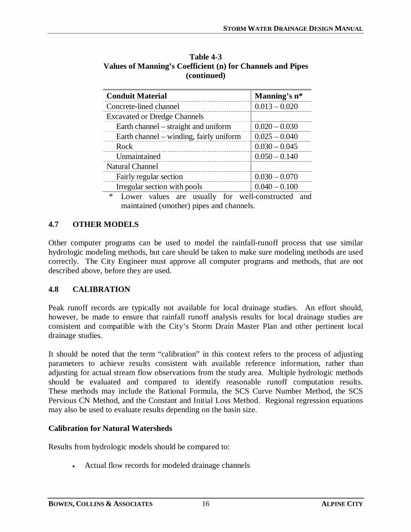
The Muskingum-Cunge method shall be used for routing. The method requires the follow parameters are inputted: Length – Total length of the reach element. Slope – Average slope for the entire reach. Invert – Optional. Typically not used. Cross Section Shape – Multiple cross sections are available to select from. Depending on the cross section chosen, additional information is required (i.e. diameter, side slope). Manning’s “n” – Average value for the entire reach. Typical values for Manning’s “n” used for storm drain conveyance facilities area shown in Table 4-3.
Table 4-3 Values of Manning’s Coefficient (n) for Channels and Pipes
Conduit Material Manning’s n* Plastic pipe 0.011 – 0.015 Steel/cast iron pipe 0.012 – 0.015 Concrete pipe 0.013 – 0.015 Corrugated metal pipe 0.012 – 0.026
STORM WATER DRAINAGE DESIGN MANUAL
BOWEN, COLLINS & ASSOCIATES 16 ALPINE CITY
Table 4-3 Values of Manning’s Coefficient (n) for Channels and Pipes
(continued)
Conduit Material Manning’s n* Concrete-lined channel 0.013 – 0.020 Excavated or Dredge Channels Earth channel – straight and uniform 0.020 – 0.030 Earth channel – winding, fairly uniform 0.025 – 0.040 Rock 0.030 – 0.045 Unmaintained 0.050 – 0.140 Natural Channel Fairly regular section 0.030 – 0.070 Irregular section with pools 0.040 – 0.100 * Lower values are usually for well-constructed and
maintained (smother) pipes and channels. 4.7 OTHER MODELS Other computer programs can be used to model the rainfall-runoff process that use similar hydrologic modeling methods, but care should be taken to make sure modeling methods are used correctly. The City Engineer must approve all computer programs and methods, that are not described above, before they are used. 4.8 CALIBRATION Peak runoff records are typically not available for local drainage studies. An effort should, however, be made to ensure that rainfall runoff analysis results for local drainage studies are consistent and compatible with the City’s Storm Drain Master Plan and other pertinent local drainage studies. It should be noted that the term “calibration” in this context refers to the process of adjusting parameters to achieve results consistent with available reference information, rather than adjusting for actual stream flow observations from the study area. Multiple hydrologic methods should be evaluated and compared to identify reasonable runoff computation results. These methods may include the Rational Formula, the SCS Curve Number Method, the SCS Pervious CN Method, and the Constant and Initial Loss Method. Regional regression equations may also be used to evaluate results depending on the basin size. Calibration for Natural Watersheds Results from hydrologic models should be compared to:
• Actual flow records for modeled drainage channels

STORM WATER DRAINAGE DESIGN MANUAL
BOWEN, COLLINS & ASSOCIATES 17 ALPINE CITY
• Streamflow records from hydrologically similar drainages in the vicinity of the study
• Regional streamflow data (in the event that streamflow records for the local area are not available).
Calibration for Urban Areas For small urban (developed) areas, the USGS published regression equations than can be used to “calibrate” hydrologic models (see Peak-flow Characteristics of Small Urban Drainages Along the Wasatch Front, Utah). The range of basin characteristics used to develop the regression equations are shown in Table 4-4.
Table 4-4 Range of Basin Characteristics Used
To Develop Regression Equations for Small Urban Drainages
Basin Characteristic Unit Range in Values Drainage Area (DA) mi2 0.085 – 0.87 Basin Slope (BS) % 0.3 – 15 Effective Impervious Area (EIA) % 22 – 57
The equations shown in Table 4-5 are only applicable to drainage basins that meet the range of values shown above.
Table 4-5 Regression Equations for Peak Flows
For Small Urban Drainages
Recurrence Interval (Years)
Equations
Average Standard Error of Estimate
(%) 10 Q10 = 0.575 DA0.285 BS0.410 EIA1.29 32 25 Q25 = 66.1 DA0.093 BS0.243 33 100 Q100 = 120 DA0.158 BS0.194 29
The unit peak runoff varies depending on slope and the drainage basin percent impervious. In general, the 10-year event for small urban drainages should be between 0.3 cfs/acre and 1.0 cfs/acre. Modification to input parameters should be considered if simulated runoff results are not within this range.
STORM WATER DRAINAGE DESIGN MANUAL
BOWEN, COLLINS & ASSOCIATES 18 ALPINE CITY
SECTION 5 EROSION CONTROL
5.1 UPDES PERMIT All new construction that disturbs one acre of land or more or more shall obtain a UPDES Storm Water General Permit for Construction Activities (Permit #UTR300000) or an alternate individual permit before construction begins. The permit requires the operator, typically the contractor, to control and eliminate storm water pollution sources through the development and implementation of a Storm Water Pollution Prevention Plan (SWPPP). The permit also requires inspection of the BMP controls either:
• At least once every 7 calendar days, or
• At least once every 14 days and within 24 hours of the end of a storm event of 0.5 inches or greater.
5.2 STORM WATER POLLUTION PREVENTION PLAN The Storm Water Pollution Prevention Plan (SWPPP) shall be prepared before the contractor can obtain the UPDES permit. Section 3.5 of the UPDES permit describes in detail what shall be included in the SWPPP. The plan shall include, among other things:
1. Possible sources of storm water pollutants
2. Selection of Best Management Practices (BMPs) to reduce or eliminate pollutant
impacts. A SWPPP template that addresses all of the information required in the SWPPP can be obtained from the State of Utah Division of Water Quality web site: http://www.waterquality.utah.gov/UPDES/stormwatercon.htm. 5.3 PERMITTING PROCESS
1. The Operator prepares a SWPPP in accordance with the UPDES Permit.
2. The Operator Submits SWPPP to City for review.
3. Once the City has reviewed the SWPPP, the operator applies for the UPDES Permit by completing the Notice of Intent (NOI) form. The form can be completed online at: https://secure.utah.gov/stormwater/main.html
4. Construction may commence only after:

STORM WATER DRAINAGE DESIGN MANUAL
BOWEN, COLLINS & ASSOCIATES 19 ALPINE CITY
i. The SWPPP has been reviewed by the City ii. The NOI has been submitted
iii. The Operator has attended a pre-construction meeting with designated City personnel to review and discuss the SWPPP, and
iv. All other applicable permits have been obtained from the City.
5. Once construction has been completed and the site stabilized, the contractor shall complete the Notice of Termination (NOT) form and submit to the Division of Water Quality.

STORM WATER DRAINAGE DESIGN MANUAL
BOWEN, COLLINS & ASSOCIATES 20 ALPINE CITY
REFERENCES Farmer, E.E., and J.E. Fletcher, February 1972, Rainfall Intensity-Duration-Frequency Relations
for the Wasatch Mountains of Northern Utah, Water Resources Research, Vol.8, No. 1. Federal Highway Administration, August 2001, Urban Drainage Design Manual, Hydraulic
Engineering Circular No. 22, Second Edition. National Oceanic and Atmospheric Administration, 2006, NOAA Atlas 14, Precipitation-
Frequency Atlas of the United States, Volume I, Version 4, Semiarid Southwest. Thomas, B.E., H.W. Hjalmarson and S.D. Waltemeyer, 1994, Methods for Estimating the
Magnitude and Frequency of Floods in the Southwestern United States, U.S. Geological Survey, Open File Report 93-419.
U.S. Army Corps of Engineers, December 1979, Project Cloudburst, Salt Lake County, Utah,
Internal File Report. U.S. Department of Agriculture, Soil Conservation Service, June 1986, Urban Hydrology for
Small Watersheds, Technical Release 55. U.S. Department of the Interior, Bureau of Reclamation, 1989, Flood Hydrology Manual. U.S. Department of the Interior, Geological Survey, March 1982. Interagency Advisory
Committee on Water Data, Office of Water Data Coordination, Hydrology Subcommittee, Bulletin No. 17B.
WRC Engineering, Inc., October 1990. Hydrologic Criteria and Drainage Design Manual, Clark
County Regional Flood Control District, Las Vegas, Nevada.