Embed Size (px)
Citation preview
1
Electronic Supplementary Information
Rational Design of a Metal-Organic Framework Host for Sulfur Storage in Fast, Long-Cycle Li-S Batteries
Junwen Zhou,a Rui Li,b Xinxin Fan,a Yifa Chen,b Ruodan Han,b Wei Li,a Jie Zheng,a Bo Wang*b and Xingguo Li*a
a Beijing National Laboratory for Molecular Sciences (BNLMS), The State Key Laboratory of Rare Earth Materials Chemistry and Applications, College of Chemistry and Molecular Engineering, Peking University, 5 Yiheyuan Road, Beijing, 100871, P.R. China.E-mail: [email protected]
b Key Laboratory of Cluster Science, Ministry of Education of China, School of Chemistry, Beijing Institute of Technology, 5 South Zhongguancun Street, Beijing, 100081, P.R. China.E-mail: [email protected]
Electronic Supplementary Material (ESI) for Energy & Environmental Science.This journal is © The Royal Society of Chemistry 2014

2
Synthesis of ZIF-8 nanocrystals:
ZIF-8 nanocrystals were synthesized through a simple mechanochemical synthetic protocol.1
Reactions were carried out in a ball mill (QM-3B, Nanjing University Instrument Factory,
China) using a 50 mL stainless steel grinding jar with five 10 mm and one 20 mm steel balls.
A solid mixture of zinc oxide (ZnO, 0.814 g, 10 mmol) and 2-methylimidazolate (2-MeIM,
1.642 g, 20 mmol) was placed into the jar and ground for 15 min at 40 Hz. After that 1 mL
ethanol was added into the jar and ground for another 30 min to give the white products of
ZIF-8 nanocrystals. The products were collected and washed with plenty amount of ethanol.
The solvent was removed under vacuum at 150 °C for 12 h, yielding the degassed MOF
powders. Particle size: 100~200 nm (Figure 3a). Pore volume (p/p0=0.2): 0.70 cm3 g-1 (Figure
3e).
Synthesis of MIL-53 (Al) and NH2-MIL-53 (Al):
MIL-53 (Al) and NH2-MIL-53 (Al) were synthesized following the reported solution
method.2 Briefly, a solid mixture of aluminum chloride hexahydrate (AlCl3·6H2O, 3.863 g, 16
mmol) and benzene-1,4-dicarboxylate (bdc, 2.658 g, 16 mmol) was dissolved in 60 mL
deionized water in a 100 mL Teflon-lined autoclave and heated at 150 °C for 9 h to give the
white products of MIL-53. Light yellow products of NH2-MIL-53 can be yielded in the same
way by using 2-aminobenzene-1,4-dicarboxylate (abdc, 2.898 g, 16 mmol) instead of
benzene-1,4-dicarboxylate. After cooling to room temperature, the products were separated by
centrifugation. In order to remove the remaining abdc or bdc, the products were heated in
N,N-dimethylformamide at 150 °C for 24 h, during which the solvent was decanted and
repeatedly replenished. After that, the products were immersed in dichloromethane and
sonicated for 2 h, during which the solvent was replenished three times. The solvent was
removed under vacuum at 150 °C for 12 h, yielding the degassed MOF powders. Particle size:
1~3 μm (MIL-53, Figure S1a) and 0.2~1 μm (NH2-MIL-53, Figure S2a). Pore volume
(p/p0=0.2): 0.54 cm3 g-1 (MIL-53, Figure S1e) and 0.57 cm3 g-1 (NH2-MIL-53, Figure S2e).
Synthesis of HKUST-1:
HKUST-1 was synthesized according to the reported solution method.3 Briefly, a solid
mixture of benzene-1,3,5-tricarboxylic acid (btc, 2.017 g, 9.6 mmol) and copper(II) nitrate
trihydrate (Cu(NO3)2·3H2O, 4.156 g, 17.2 mmol) was dissolved in 100 mL mixed solvent of
N,N-dimethylformamide, ethanol and deionized water (v/v/v 1:1:1) in a 250 mL tightly
capped bottle and heated at 85 °C for 20 h to give the blue crystals of HKUST-1. After

3
cooling to room temperature, the products were separated by centrifugation and immersed in
methanol under sonication for 2 h, during which the solvent was replenished repeatedly. The
solvent was removed under vacuum at 150 °C for 12 h, yielding the degassed MOF powders.
Particle size: >10 μm (Figure S3a). Pore volume (p/p0=0.2): 0.67 cm3 g-1 (Figure S3e).
Synthesis of microsized ZIF-8 particles (ZIF-8-M and ZIF-8-L):
ZIF-8-M was synthesized with modification of the reported solution method.4 Typically, zinc
nitrate hexahydrate (Zn(NO3)2·6H2O, 2.975 g, 10 mmol) was dissolved in 100 mL of
methanol. A second solution was prepared by dissolving 2-methylimidazole (2-MeIM, 3.284
g, 40 mmol) and sodium acetate trihydrate (NaOAc·3H2O, 5.443 g, 40 mmol) in 100 mL of
methanol. The latter clear solution was poured into the former clear solution under stirring.
Stirring was stopped after combining the two solutions. After 24 h at room temperature, the
resulting white products were isolated by centrifugation and washed with ethanol by three
dispersion-sonication-centrifugation cycles. ZIF-8-L can be yielded in the same way by using
ethanol as the reaction solvent without the addition of NaOAc·3H2O. The solvent was
removed under vacuum at 120 °C for 12 h, yielding the degassed MOF powders. Particle size:
0.8~1.2 μm (ZIF-8-M, Figure S4a) and 2.5~3.5 μm (ZIF-8-L, Figure S5a). Pore volume
(p/p0=0.2): 0.66 cm3 g-1 (ZIF-8-M, Figure S4c) and 0.68 cm3 g-1 (ZIF-8-L, Figure S5c).
Synthesis of S/MOF composites:
In a typical synthesis, 200 mg degassed MOF powders were first ground with 200 mg sulfur
in an argon-filled glove box for 30 min, and then subjected to a heating process under argon
for 12 h. The heating temperatures for the four MOFs were different: 155 °C for ZIF-8 and
MIL-53, and 135 °C for HKUST-1 and NH2-MIL-53. A lower temperature was chosen for the
latter two MOFs, because we observed that they would not keep inert to sulfur after heating at
155 °C for 12 h, suggested by powder X-ray diffraction (PXRD, data not shown). All the
degassed MOFs and S/MOF samples were kept in an argon-filled glove box prior use.
Discussions on the effect of sulfur loading:
For making a preliminary comparison among different MOFs, S loadings for all MOFs in the
main text are fixed at 1:1 (S/MOF g g-1). This ratio is below the maximum loading level of
MIL-53 (1.12:1, based on the density of sulfur, 2.07 g cm-3), which has the lowest
experimental pore volume (0.54 cm3 g-1). Therefore for all selected MOFs, it is reasonable
that most sulfur is embedded within the MOF pores at this S loading. To understand the S

4
loading effect, we used ZIF-8-M as a prototype and prepared another two S/ZIF-8-M
composites with extreme loadings: one is 1:3, leaving plenty of empty pores, and the other is
3:1, with substantial amount of sulfur unprotected by MOF. We tested the three composites
(1:3, 1:1 and 3:1) with the same CB and PVDF contents (30 wt% and 10 wt%, respectively) at
0.5C for 100 cycles, as shown in Figure S6. Extremely low S loading (1:3) leads to rather low
capacity but exceptional retention. Clearly, that less sulfur disperses at the outermost areas of
the MOF host would have two effects: (i) less sulfur could get in contact with the conductive
agent and become electrochemically active – low capacity; (ii) dissolved polysulfides need
more time to escape from MOF – high retention. The opposite combination (high capacity and
poor retention) is observed when S loading is exceedingly high (3:1). Therefore it is true that
one should carefully adjust the S loading to deal with this tradeoff if the performance of a
certain MOF is to be optimized.
References
1. R. Li, X. Ren, J. Zhao, X. Feng, X. Jiang, X. Fan, Z. Lin, X. Li, C. Hu and B. Wang, J.
Mater. Chem. A, 2014, 2, 2168.
2. M. Pera-Titus, T. Lescouet, S. Aguado and D. Farrusseng, J. Phys. Chem. C, 2012,
116, 9507.
3. J. L. C. Rowsell and O. M. Yaghi, J. Am. Chem. Soc., 2006, 128, 1304.
4. J. Cravillon, R. Nayuk, S. Springer, A. Feldhoff, K. Huber and M. Wiebcke, Chem.
Mater., 2011, 23, 2130.

5
Figure S1. Characterization of the sulfur infiltration of MIL-53 (Al): SEM images of (a) MIL-53 and
(b) S/MIL-53. (c) EDS mapping of the sulfur distribution in S/MIL-53. (d) PXRD patterns of sulfur
and MIL-53 after ground (S+MIL-53) and after heated (S/MIL-53). (e) N2 adsorption isotherms of
MIL-53 and S/MIL-53. (f) TGA of MIL-53 and S/MIL-53.

6
Figure S2. Characterization of the sulfur infiltration of NH2-MIL-53 (Al): SEM images of (a) NH2-
MIL-53 and (b) S/NH2-MIL-53. (c) EDS mapping of the sulfur distribution in S/NH2-MIL-53. (d)
PXRD patterns of sulfur and NH2-MIL-53 after ground (S+NH2-MIL-53) and after heated (S/NH2-
MIL-53). (e) N2 adsorption isotherms of NH2-MIL-53 and S/NH2-MIL-53. (f) TGA of NH2-MIL-53
and S/NH2-MIL-53.

7
Figure S3. Characterization of the sulfur infiltration of HKUST-1: SEM images of (a) HKUST-1 and
(b) S/HKUST-1. (c) EDS mapping of the sulfur distribution in S/HKUST-1. (d) PXRD patterns of
sulfur and HKUST-1 after ground (S+HKUST-1) and after heated (S/HKUST-1). (e) N2 adsorption
isotherms of HKUST-1 and S/HKUST-1. (f) TGA of HKUST-1 and S/HKUST-1.

8
Figure S4. Characterization of ZIF-8-M: (a) SEM images of ZIF-8-M. (b) PXRD patterns of sulfur
and ZIF-8-M after ground (S+ZIF-8-M) and after heated (S/ZIF-8-M). (c) N2 adsorption isotherm of
ZIF-8-M.
Figure S5. Characterization of ZIF-8-L: (a) SEM images of ZIF-8-L. (b) PXRD patterns of sulfur and
ZIF-8-L after ground (S+ZIF-8-L) and after heated (S/ZIF-8-L). (c) N2 adsorption isotherm of ZIF-8-L.

9
Figure S6. Performances of S/ZIF-8-M composites with different sulfur loadings at 0.5C.
Figure S7. Performances of S/ZIF-8 at 0.2C: Voltage profiles in electrolyte (a) with and (b)
without LiNO3 additive. (c) Discharge capacities and corresponding Coulombic efficiencies.
10
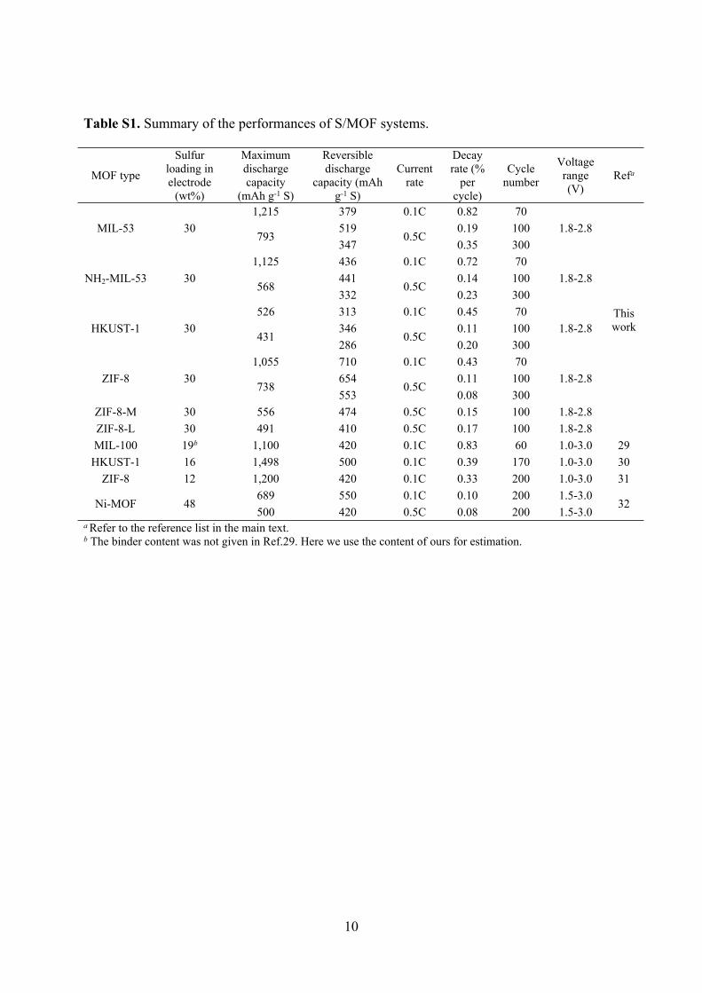
Table S1. Summary of the performances of S/MOF systems.
MOF type
Sulfur loading in electrode
(wt%)
Maximum discharge capacity
(mAh g-1 S)
Reversible discharge
capacity (mAh g-1 S)
Current rate
Decay rate (%
per cycle)
Cycle number
Voltage range (V)
Refa
1,215 379 0.1C 0.82 70519 0.19 100MIL-53 30
793347
0.5C0.35 300
1.8-2.8
1,125 436 0.1C 0.72 70441 0.14 100NH2-MIL-53 30
568332
0.5C0.23 300
1.8-2.8
526 313 0.1C 0.45 70346 0.11 100HKUST-1 30
431286
0.5C0.20 300
1.8-2.8
1,055 710 0.1C 0.43 70654 0.11 100ZIF-8 30
738553
0.5C0.08 300
1.8-2.8
ZIF-8-M 30 556 474 0.5C 0.15 100 1.8-2.8ZIF-8-L 30 491 410 0.5C 0.17 100 1.8-2.8
This work
MIL-100 19b 1,100 420 0.1C 0.83 60 1.0-3.0 29HKUST-1 16 1,498 500 0.1C 0.39 170 1.0-3.0 30
ZIF-8 12 1,200 420 0.1C 0.33 200 1.0-3.0 31689 550 0.1C 0.10 200 1.5-3.0
Ni-MOF 48500 420 0.5C 0.08 200 1.5-3.0
32
a Refer to the reference list in the main text.b The binder content was not given in Ref.29. Here we use the content of ours for estimation.