Embed Size (px)
Citation preview

SUSE Linux Enterprise Server 15 SP3
Storage AdministrationGuide

Storage Administration GuideSUSE Linux Enterprise Server 15 SP3
This guide provides information about how to manage storage devices on a SUSELinux Enterprise Server.
Publication Date: March 18, 2022
SUSE LLC1800 South Novell PlaceProvo, UT 84606USA
https://documentation.suse.com
Copyright © 2006– 2022 SUSE LLC and contributors. All rights reserved.

Permission is granted to copy, distribute and/or modify this document under the terms of the GNU Free
Documentation License, Version 1.2 or (at your option) version 1.3; with the Invariant Section being this
copyright notice and license. A copy of the license version 1.2 is included in the section entitled “GNU
Free Documentation License”.
For SUSE trademarks, see https://www.suse.com/company/legal/ . All other third-party trademarks are the
property of their respective owners. Trademark symbols (®, ™ etc.) denote trademarks of SUSE and its
affiliates. Asterisks (*) denote third-party trademarks.
All information found in this book has been compiled with utmost attention to detail. However, this does
not guarantee complete accuracy. Neither SUSE LLC, its affiliates, the authors nor the translators shall be
held liable for possible errors or the consequences thereof.

Contents
Preface xiv1 Available documentation xiv
2 Improving the documentation xiv
3 Documentation conventions xv
4 Support xvii
Support statement for SUSE Linux Enterprise Server xvii • Technology
previews xviii
I FILE SYSTEMS AND MOUNTING 1
1 Overview of file systems in Linux 21.1 Terminology 3
1.2 Btrfs 3
Key features 4 • The root file system setup on SUSE Linux
Enterprise Server 4 • Migration from ReiserFS and ext file systems
to Btrfs 9 • Btrfs administration 10 • Btrfs quota support
for subvolumes 10 • Swapping on Btrfs 14 • Btrfs send/
receive 14 • Data deduplication support 18 • Deleting subvolumes
from the root file system 19
1.3 XFS 20
High scalability by using allocation groups 20 • High performance through
ecient management of disk space 20 • Preallocation to avoid file system
fragmentation 21
1.4 Ext2 21
1.5 Ext3 22
Easy and highly reliable upgrades from ext2 22 • Converting an ext2 file
system into ext3 23
iv Storage Administration Guide
1.6 Ext4 23
Reliability and performance 24 • Ext4 file system inode size and number of
inodes 24 • Upgrading to Ext4 27
1.7 ReiserFS 28
1.8 Other supported file systems 29
1.9 Large file support in Linux 30
1.10 Linux kernel storage limitations 31
1.11 Troubleshooting file systems 32
Btrfs error: no space is left on device 32 • Freeing unused file
system blocks 34 • Btrfs: balancing data across devices 35 • No
defragmentation on SSDs 36
1.12 More information 36
2 Resizing file systems 37
2.1 Use cases 37
2.2 Guidelines for resizing 37
File systems that support resizing 38 • Increasing the size of a file
system 38 • Decreasing the size of a file system 39
2.3 Changing the size of a Btrfs file system 39
2.4 Changing the size of an XFS file system 40
2.5 Changing the size of an ext2, ext3, or ext4 file system 41
3 Mounting storage devices 42
3.1 Understanding UUIDs 42
3.2 Persistent device names with udev 42
3.3 Mounting network storage devices 43
4 Multi-tier caching for block device operations 44
4.1 General terminology 44
v Storage Administration Guide

4.2 Caching modes 45
4.3 bcache 46
Main features 46 • Setting up a bcache device 46 • bcache
configuration using sysfs 48
4.4 lvmcache 48
Configuring lvmcache 48 • Removing a cache pool 50
II LOGICAL VOLUMES (LVM) 52
5 LVM configuration 535.1 Understanding the logical volume manager 53
5.2 Creating volume groups 55
5.3 Creating logical volumes 58
Thinly provisioned logical volumes 61 • Creating mirrored volumes 62
5.4 Automatically activating non-root LVM volume groups 63
5.5 Resizing an existing volume group 64
5.6 Resizing a logical volume 65
5.7 Deleting a volume group or a logical volume 67
5.8 Using LVM commands 68
Resizing a logical volume with commands 71 • Using LVM cache
volumes 73
5.9 Tagging LVM2 storage objects 74
Using LVM2 tags 75 • Requirements for creating LVM2
tags 75 • Command line tag syntax 76 • Configuration
file syntax 76 • Using tags for a simple activation control in a
cluster 78 • Using tags to activate on preferred hosts in a cluster 78
6 LVM volume snapshots 82
6.1 Understanding volume snapshots 82
6.2 Creating Linux snapshots with LVM 84
vi Storage Administration Guide

6.3 Monitoring a snapshot 84
6.4 Deleting Linux snapshots 85
6.5 Using snapshots for virtual machines on a virtual host 85
6.6 Merging a snapshot with the source logical volume to revert changes orroll back to a previous state 87
III SOFTWARE RAID 90
7 Software RAID configuration 917.1 Understanding RAID levels 91
RAID 0 91 • RAID 1 92 • RAID 2 and
RAID 3 92 • RAID 4 92 • RAID 5 92 • RAID 6 93 • Nested and
complex RAID levels 93
7.2 Soft RAID configuration with YaST 93
RAID names 96
7.3 Monitoring software RAIDs 97
7.4 More information 97
8 Configuring software RAID for the root partition 98
8.1 Prerequisites for using a software RAID device for the rootpartition 98
8.2 Setting up the system with a software RAID device for the root (/)partition 99
9 Creating software RAID 10 devices 106
9.1 Creating nested RAID 10 devices with mdadm 106
Creating nested RAID 10 (1+0) with mdadm 107 • Creating nested RAID 10
(0+1) with mdadm 109
9.2 Creating a complex RAID 10 111
Number of devices and replicas in the complex
RAID 10 112 • Layout 113 • Creating a complex RAID 10 with the YaST
partitioner 115 • Creating a complex RAID 10 with mdadm 118
vii Storage Administration Guide

10 Creating a degraded RAID array 121
11 Resizing software RAID arrays with mdadm 123
11.1 Increasing the size of a software RAID 124
Increasing the size of component partitions 125 • Increasing the size of the
RAID array 126 • Increasing the size of the file system 127
11.2 Decreasing the size of a software RAID 128
Decreasing the size of the file system 128 • Decreasing the size of the RAID
array 128 • Decreasing the size of component partitions 129
12 Storage enclosure LED utilities for MD softwareRAIDs 132
12.1 The storage enclosure LED monitor service 133
12.2 The storage enclosure LED control application 134
Pattern names 135 • List of devices 138 • Examples 139
12.3 More information 139
13 Troubleshooting software RAIDs 140
13.1 Recovery after failing disk is back again 140
IV NETWORK STORAGE 142
14 iSNS for Linux 14314.1 How iSNS works 143
14.2 Installing iSNS server for Linux 145
14.3 Configuring iSNS discovery domains 146
Creating iSNS discovery domains 147 • Adding iSCSI nodes to a discovery
domain 148
14.4 Starting the iSNS service 150
14.5 More information 150
viii Storage Administration Guide

15 Mass storage over IP networks: iSCSI 151
15.1 Installing the iSCSI LIO target server and iSCSI initiator 152
15.2 Setting up an iSCSI LIO target server 153
iSCSI LIO target service start-up and firewall settings 153 • Configuring
authentication for discovery of iSCSI LIO targets and initiators 154 • Preparing
the storage space 156 • Setting up an iSCSI LIO target
group 157 • Modifying an iSCSI LIO target group 160 • Deleting an iSCSI
LIO target group 161
15.3 Configuring iSCSI initiator 162
Using YaST for the iSCSI initiator configuration 162 • Setting up the iSCSI
initiator manually 165 • The iSCSI initiator databases 166
15.4 Setting up software targets using targetcli-fb 168
15.5 Using iSCSI disks when installing 172
15.6 Troubleshooting iSCSI 173
Portal error when setting up target LUNs on an iSCSI LIO target
server 173 • iSCSI LIO targets are not visible from other
computers 174 • Data packets dropped for iSCSI trac 174 • Using iSCSI
volumes with LVM 174 • iSCSI targets are mounted when the configuration
file is set to manual 175
15.7 iSCSI LIO target terminology 175
15.8 More information 177
16 Fibre Channel storage over Ethernet networks:FCoE 178
16.1 Configuring FCoE interfaces during the installation 179
16.2 Installing FCoE and the YaST FCoE client 180
16.3 Managing FCoE services with YaST 181
16.4 Configuring FCoE with commands 184
16.5 Managing FCoE instances with the FCoE administration tool 185
ix Storage Administration Guide

16.6 More information 187
17 NVMe over Fabric 189
17.1 Overview 189
17.2 Setting up an NVMe over Fabric host 189
Installing command line client 189 • Discovering NVMe
over Fabric targets 190 • Connecting to NVMe over Fabric
targets 190 • Multipathing 191
17.3 Setting up an NVMe over Fabric target 192
Installing command line client 192 • Configuration steps 192 • Back up
and restore target configuration 195
17.4 Special hardware configuration 195
Overview 195 • Broadcom 195 • Marvell 196
17.5 More information 196
18 Managing multipath I/O for devices 198
18.1 Understanding multipath I/O 198
18.2 Hardware support 198
Storage arrays that are automatically detected for multipathing 199 • Tested
storage arrays for multipathing support 201 • Storage arrays that require
specific hardware handlers 202
18.3 Planning for multipathing 202
Prerequisites 202 • Disk management tasks 203 • Software
RAIDs 203 • High-availability solutions 204 • Always keep the initrd in
synchronization with the system configuration 204
18.4 Multipath management tools 204
Device mapper multipath module 205 • Multipath I/O management
tools 207 • Using MDADM for multipathed devices 208 • The multipath
command 208 • The mpathpersist utility 211
x Storage Administration Guide

18.5 Configuring the system for multipathing 212
Enabling, disabling, starting, and stopping multipath I/O
services 212 • Preparing SAN devices for multipathing 213 • Partitioning
multipath devices 214
18.6 Creating or modifying the /etc/multipath.conf file 215
Creating the /etc/multipath.conf file 215 • Sections in the /etc/
multipath.conf file 216 • Verifying the multipath setup in the /etc/
multipath.conf file 217 • Applying the /etc/multipath.conf file changes to
update the multipath maps 219 • Generating a WWID 219
18.7 Configuring default policies for polling, queuing, and failback 220
18.8 Blacklisting non-multipath devices 221
18.9 Configuring user-friendly names or alias names 225
Multipath device names in HA clusters 229
18.10 Configuring path failover policies and priorities 230
Configuring the path failover policies 231 • Configuring failover
priorities 231 • Reporting target path groups 239
18.11 Configuring multipath I/O for the root device 240
Enabling multipath I/O at install time 240 • Enabling multipath I/O for an
existing root device 243 • Disabling multipath I/O on the root device 243
18.12 Configuring multipath I/O for an existing software RAID 243
18.13 Using LVM2 on multipath devices 246
18.14 Best practice 246
Scanning for new devices without rebooting 246 • Scanning for new
partitioned devices without rebooting 248 • Viewing multipath I/O
status 250 • Managing I/O in error situations 251 • Resolving stalled
I/O 253 • Configuring default settings for IBM Z devices 253 • Using
multipath with NetApp devices 254 • Using --noflush with multipath
devices 254 • SAN timeout settings when the root device is
multipathed 255
xi Storage Administration Guide

18.15 Troubleshooting MPIO 255
Installing GRUB2 on multipath devices 255 • The system exits to emergency
shell at boot when multipath is enabled 256 • PRIO settings for individual
devices fail after upgrading to multipath 0.4.9 or later 259 • PRIO
settings with arguments fail after upgrading to multipath-tools-0.4.9 or
later 259 • Technical information documents 260
19 Sharing file systems with NFS 261
19.1 Overview 261
19.2 Installing NFS server 262
19.3 Configuring NFS server 263
Exporting file systems with YaST 263 • Exporting file systems
manually 265 • NFS with Kerberos 268
19.4 Configuring clients 268
Importing file systems with YaST 268 • Importing file systems
manually 269 • Parallel NFS (pNFS) 271
19.5 Managing Access Control Lists over NFSv4 272
19.6 More information 274
19.7 Gathering information for NFS troubleshooting 274
Common troubleshooting 274 • Advanced NFS debugging 276
20 Samba 279
20.1 Terminology 279
20.2 Installing a Samba server 281
20.3 Starting and stopping Samba 281
20.4 Configuring a Samba server 281
Configuring a Samba server with YaST 281 • Configuring the server
manually 284
20.5 Configuring clients 288
Configuring a Samba client with YaST 288 • Mounting SMB1/CIFS shares on
clients 289
xii Storage Administration Guide
20.6 Samba as login server 290
20.7 Samba server in the network with Active Directory 291
20.8 Advanced topics 292
Transparent file compression on Btrfs 293 • Snapshots 294
20.9 More information 301
21 On-demand mounting with autofs 303
21.1 Installation 303
21.2 Configuration 303
The master map file 303 • Map files 305
21.3 Operation and debugging 306
Controlling the autofs service 306 • Debugging automounter
problems 307
21.4 Auto-mounting an NFS share 308
21.5 Advanced topics 309
/net mount point 309 • Using wild cards to auto-mount
subdirectories 309 • Auto-mounting CIFS file system 310
A GNU licenses 311
xiii Storage Administration Guide

Preface
1 Available documentation
Online documentation
The online documentation for this product is available at https://documenta-
tion.suse.com/#sles . Browse or download the documentation in various formats.Find the online documentation for other products at https://documentation.suse.com/ .
Note: Latest updatesThe latest documentation updates are usually available in the English version of thedocumentation.
Release notes
For release notes, see https://www.suse.com/releasenotes/ .
In your system
For offline use, nd documentation in your installed system under /usr/share/doc . Manycommands are also described in detail in their manual pages. To view them, run man ,followed by a specific command name. If the man command is not installed on your system,install it with sudo zypper install man .
2 Improving the documentationYour feedback and contributions to this documentation are welcome! Several channels are avail-able:
Service requests and support
For services and support options available for your product, refer to https://www.suse.com/
support/ .To open a service request, you need a subscription at SUSE Customer Center. Go to https://
scc.suse.com/support/requests , log in, and click Create New.
Bug reports
xiv Available documentation SLES 15 SP3

Report issues with the documentation at https://bugzilla.suse.com/ . To simplify thisprocess, you can use the Report Documentation Bug links next to headlines in the HTML ver-sion of this document. These preselect the right product and category in Bugzilla and adda link to the current section. You can start typing your bug report right away. A Bugzillaaccount is required.
Contributions
To contribute to this documentation, use the Edit Source links next to headlines in theHTML version of this document. They take you to the source code on GitHub, where youcan open a pull request. A GitHub account is required.For more information about the documentation environment used for this doc-umentation, see the repository's README (https://github.com/SUSE/doc-sle/blob/mas-
ter/README.adoc) .
Alternatively, you can report errors and send feedback concerning the documentation [email protected] . Make sure to include the document title, the product version andthe publication date of the documentation. Refer to the relevant section number and title(or include the URL) and provide a concise description of the problem.
3 Documentation conventionsThe following notices and typographical conventions are used in this documentation:
/etc/passwd : directory names and le names
PLACEHOLDER : replace PLACEHOLDER with the actual value
PATH : the environment variable PATH
ls , --help : commands, options, and parameters
user : users or groups
package name : name of a package
Alt , Alt – F1 : a key to press or a key combination; keys are shown in uppercase as ona keyboard
File, File Save As: menu items, buttons
xv Documentation conventions SLES 15 SP3

AMD/Intel This paragraph is only relevant for the AMD64/Intel 64 architecture. The ar-rows mark the beginning and the end of the text block. IBM Z, POWER This paragraph is only relevant for the architectures IBM Z and POWER .
The arrows mark the beginning and the end of the text block.
Dancing Penguins (Chapter Penguins, ↑Another Manual): This is a reference to a chapter inanother manual.
Commands that must be run with root privileges. Often you can also prefix these com-mands with the sudo command to run them as non-privileged user.
# command> sudo command
Commands that can be run by non-privileged users.
> command
Notices
Warning: Warning noticeVital information you must be aware of before proceeding. Warns you about securityissues, potential loss of data, damage to hardware, or physical hazards.
Important: Important noticeImportant information you should be aware of before proceeding.
Note: Note noticeAdditional information, for example about differences in software versions.
Tip: Tip noticeHelpful information, like a guideline or a piece of practical advice.
xvi Documentation conventions SLES 15 SP3

4 SupportFind the support statement for SUSE Linux Enterprise Server and general information abouttechnology previews below. For details about the product life cycle, see Book “Upgrade Guide”,
Chapter 2 “Life cycle and support”.
If you are entitled to support, nd details on how to collect information for a support ticket inBook “Administration Guide”, Chapter 40 “Gathering system information for support”.
4.1 Support statement for SUSE Linux Enterprise Server
To receive support, you need an appropriate subscription with SUSE. To view the specific supportofferings available to you, go to https://www.suse.com/support/ and select your product.
The support levels are defined as follows:
L1
Problem determination, which means technical support designed to provide compatibilityinformation, usage support, ongoing maintenance, information gathering and basic trou-bleshooting using available documentation.
L2
Problem isolation, which means technical support designed to analyze data, reproducecustomer problems, isolate problem area and provide a resolution for problems not re-solved by Level 1 or prepare for Level 3.
L3
Problem resolution, which means technical support designed to resolve problems by en-gaging engineering to resolve product defects which have been identified by Level 2 Sup-port.
For contracted customers and partners, SUSE Linux Enterprise Server is delivered with L3 sup-port for all packages, except for the following:
technology previews.
sound, graphics, fonts, and artwork.
packages that require an additional customer contract.
xvii Support SLES 15 SP3

some packages shipped as part of the module Workstation Extension are L2-supported only.
packages with names ending in -devel (containing header les and similar developerresources) will only be supported together with their main packages.
SUSE will only support the usage of original packages. That is, packages that are unchangedand not recompiled.
4.2 Technology previews
Technology previews are packages, stacks, or features delivered by SUSE to provide glimpsesinto upcoming innovations. The previews are included for your convenience to give you thechance to test new technologies within your environment. We would appreciate your feedback!If you test a technology preview, contact your SUSE representative and let them know aboutyour experience and use cases. Your input is helpful for future development.
However, technology previews come with the following limitations:
Technology previews are still in development. Therefore, they may be functionally incom-plete, unstable, or in other ways not suitable for production use.
Technology previews are not supported.
Technology previews may only be available for specific hardware architectures.
Details and functionality of technology previews are subject to change. As a result, up-grading to subsequent releases of a technology preview may be impossible and require afresh installation.
Technology previews can be dropped at any time. For example, if SUSE discovers that apreview does not meet the customer or market needs, or does not prove to comply withenterprise standards. SUSE does not commit to providing a supported version of such tech-nologies in the future.
For an overview of technology previews shipped with your product, see the release notes athttps://www.suse.com/releasenotes/ .
xviii Technology previews SLES 15 SP3

I File systems and mounting
1 Overview of file systems in Linux 2
2 Resizing file systems 37
3 Mounting storage devices 42
4 Multi-tier caching for block device operations 44

1 Overview of file systems in Linux
SUSE Linux Enterprise Server ships with different le systems from which tochoose, including Btrfs, Ext4, Ext3, Ext2 and XFS. Each le system has its ownadvantages and disadvantages. For a side-by-side feature comparison of the ma-jor le systems in SUSE Linux Enterprise Server, see https://www.suse.com/re-
leasenotes/x86_64/SUSE-SLES/15-SP3/#file-system-comparison (Comparison of sup-ported le systems). This chapter contains an overview of how these le systemswork and what advantages they offer.
With SUSE Linux Enterprise 12, Btrfs is the default le system for the operating system andXFS is the default for all other use cases. SUSE also continues to support the Ext family of lesystems and OCFS2. By default, the Btrfs le system will be set up with subvolumes. Snapshotswill be automatically enabled for the root le system using the snapper infrastructure. For moreinformation about snapper, refer to Book “Administration Guide”, Chapter 7 “System recovery and
snapshot management with Snapper”.
Professional high-performance setups might require a highly available storage system. To meetthe requirements of high-performance clustering scenarios, SUSE Linux Enterprise Server in-cludes OCFS2 (Oracle Cluster File System 2) and the Distributed Replicated Block Device (DRBD)in the High Availability Extension add-on. These advanced storage systems are not coveredin this guide. For information, see the Administration Guide for the SUSE Linux Enterprise High
Availability Extension (https://documentation.suse.com/sle-ha-15/html/SLE-HA-all/book-administra-
tion.html) .
It is very important to remember that no le system best suits all kinds of applications. Eachle system has its particular strengths and weaknesses, which must be taken into account. Inaddition, even the most sophisticated le system cannot replace a reasonable backup strategy.
The terms data integrity and data consistency, when used in this section, do not refer to theconsistency of the user space data (the data your application writes to its les). Whether thisdata is consistent must be controlled by the application itself.
Unless stated otherwise in this section, all the steps required to set up or change partitions andle systems can be performed by using the YaST Partitioner (which is also strongly recommend-ed). For information, see Book “Deployment Guide”, Chapter 10 “Expert Partitioner”.
2 SLES 15 SP3

1.1 Terminology
metadata
A data structure that is internal to the le system. It ensures that all of the on-disk datais properly organized and accessible. Almost every le system has its own structure ofmetadata, which is one reason the le systems show different performance characteristics.It is extremely important to maintain metadata intact, because otherwise all data on thele system could become inaccessible.
inode
A data structure on a le system that contains a variety of information about a le, includ-ing size, number of links, pointers to the disk blocks where the le contents are actuallystored, and date and time of creation, modification, and access.
journal
In the context of a le system, a journal is an on-disk structure containing a type of login which the le system stores what it is about to change in the le system’s metadata.Journaling greatly reduces the recovery time of a le system because it has no need forthe lengthy search process that checks the entire le system at system start-up. Instead,only the journal is replayed.
1.2 BtrfsBtrfs is a copy-on-write (COW) le system developed by Chris Mason. It is based on COW-friendlyB-trees developed by Ohad Rodeh. Btrfs is a logging-style le system. Instead of journaling theblock changes, it writes them in a new location, then links the change in. Until the last write,the new changes are not committed.
3 Terminology SLES 15 SP3

1.2.1 Key features
Btrfs provides fault tolerance, repair, and easy management features, such as the following:
Writable snapshots that allow you to easily roll back your system if needed after applyingupdates, or to back up les.
Subvolume support: Btrfs creates a default subvolume in its assigned pool of space. It allowsyou to create additional subvolumes that act as individual le systems within the samepool of space. The number of subvolumes is limited only by the space allocated to the pool.
The online check and repair functionality scrub is available as part of the Btrfs commandline tools. It verifies the integrity of data and metadata, assuming the tree structure is ne.You can run scrub periodically on a mounted le system; it runs as a background processduring normal operation.
Different RAID levels for metadata and user data.
Different checksums for metadata and user data to improve error detection.
Integration with Linux Logical Volume Manager (LVM) storage objects.
Integration with the YaST Partitioner and AutoYaST on SUSE Linux Enterprise Server. Thisalso includes creating a Btrfs le system on Multiple Devices (MD) and Device Mapper(DM) storage configurations.
Offline migration from existing Ext2, Ext3, and Ext4 le systems.
Boot loader support for /boot , allowing to boot from a Btrfs partition.
Multivolume Btrfs is supported in RAID0, RAID1, and RAID10 profiles in SUSE Linux En-terprise Server 15 SP3. Higher RAID levels are not supported yet, but might be enabledwith a future service pack.
Use Btrfs commands to set up transparent compression.
1.2.2 The root file system setup on SUSE Linux Enterprise Server
By default, SUSE Linux Enterprise Server is set up using Btrfs and snapshots for the root par-tition. Snapshots allow you to easily roll back your system if needed after applying updates,or to back up les. Snapshots can easily be managed with the SUSE Snapper infrastructure as
4 Key features SLES 15 SP3

explained in Book “Administration Guide”, Chapter 7 “System recovery and snapshot management with
Snapper”. For general information about the SUSE Snapper project, see the Snapper Portal wikiat OpenSUSE.org (http://snapper.io ).
When using a snapshot to roll back the system, it must be ensured that data such as user's homedirectories, Web and FTP server contents or log les do not get lost or overwritten during a rollback. This is achieved by using Btrfs subvolumes on the root le system. Subvolumes can beexcluded from snapshots. The default root le system setup on SUSE Linux Enterprise Server asproposed by YaST during the installation contains the following subvolumes. They are excludedfrom snapshots for the reasons given below.
/boot/grub2/i386-pc , /boot/grub2/x86_64-efi , /boot/grub2/powerpc-ieee1275 , /
boot/grub2/s390x-emu
A rollback of the boot loader configuration is not supported. The directories listed aboveare architecture-specific. The rst two directories are present on AMD64/Intel 64 ma-chines, the latter two on IBM POWER and on IBM Z, respectively.
/home
If /home does not reside on a separate partition, it is excluded to avoid data loss on roll-backs.
/opt
Third-party products usually get installed to /opt . It is excluded to avoid uninstallingthese applications on rollbacks.
/srv
Contains data for Web and FTP servers. It is excluded to avoid data loss on rollbacks.
/tmp
All directories containing temporary les and caches are excluded from snapshots.
/usr/local
This directory is used when manually installing software. It is excluded to avoid unin-stalling these installations on rollbacks.
/var
This directory contains many variable les, including logs, temporary caches, third partyproducts in /var/opt , and is the default location for virtual machine images and databas-es. Therefore this subvolume is created to exclude all of this variable data from snapshotsand has Copy-On-Write disabled.
5 The root file system setup on SUSE Linux Enterprise Server SLES 15 SP3

Warning: Support for rollbacksRollbacks are only supported by SUSE if you do not remove any of the preconfiguredsubvolumes. You may, however, add subvolumes using the YaST Partitioner.
1.2.2.1 Mounting compressed Btrfs file systems
Note: GRUB 2 and compressed rootGRUB 2 cannot boot from lzo or zstd compressed root le systems. Use zlib compression,or create a separate /boot partition if you wish to use lzo or zstd compression for root.
The Btrfs le system supports transparent compression. While enabled, Btrfs compresses ledata when written and uncompresses le data when read.
Use the compress or compress-force mount option and select the compression algorithm,zstd , lzo , or zlib (the default). zlib compression has a higher compression ratio while lzois faster and takes less CPU load. The zstd algorithm offers a modern compromise, with perfor-mance close to lzo and compression ratios similar to zlib.
For example:
# mount -o compress=zstd /dev/sdx /mnt
In case you create a le, write to it, and the compressed result is greater or equal to the uncom-pressed size, Btrfs will skip compression for future write operations forever for this le. If youdo not like this behavior, use the compress-force option. This can be useful for les that havesome initial non-compressible data.
Note, compression takes effect for new les only. Files that were written without compressionare not compressed when the le system is mounted with the compress or compress-forceoption. Furthermore, les with the nodatacow attribute never get their extents compressed:
# chattr +C FILE# mount -o nodatacow /dev/sdx /mnt
In regard to encryption, this is independent from any compression. After you have written somedata to this partition, print the details:
# btrfs filesystem show /mntbtrfs filesystem show /mnt
6 The root file system setup on SUSE Linux Enterprise Server SLES 15 SP3

Label: 'Test-Btrfs' uuid: 62f0c378-e93e-4aa1-9532-93c6b780749d Total devices 1 FS bytes used 3.22MiB devid 1 size 2.00GiB used 240.62MiB path /dev/sdb1
If you want this to be permanent, add the compress or compress-force option into the /etc/fstab configuration le. For example:
UUID=1a2b3c4d /home btrfs subvol=@/home,compress 0 0
1.2.2.2 Mounting subvolumes
A system rollback from a snapshot on SUSE Linux Enterprise Server is performed by bootingfrom the snapshot rst. This allows you to check the snapshot while running before doing therollback. Being able to boot from snapshots is achieved by mounting the subvolumes (whichwould normally not be necessary).
In addition to the subvolumes listed in Section 1.2.2, “The root file system setup on SUSE Linux Enter-
prise Server” a volume named @ exists. This is the default subvolume that will be mounted as theroot partition ( / ). The other subvolumes will be mounted into this volume.
When booting from a snapshot, not the @ subvolume will be used, but rather the snapshot. Theparts of the le system included in the snapshot will be mounted read-only as / . The othersubvolumes will be mounted writable into the snapshot. This state is temporary by default: theprevious configuration will be restored with the next reboot. To make it permanent, execute thesnapper rollback command. This will make the snapshot that is currently booted the newdefault subvolume, which will be used after a reboot.
1.2.2.3 Checking for free space
File system usage is usually checked by running the df command. On a Btrfs le system, theoutput of df can be misleading, because in addition to the space the raw data allocates, a Btrfsle system also allocates and uses space for metadata.
Consequently a Btrfs le system may report being out of space even though it seems that plentyof space is still available. In that case, all space allocated for the metadata is used up. Use thefollowing commands to check for used and available space on a Btrfs le system:
btrfs filesystem show
> sudo btrfs filesystem show /
7 The root file system setup on SUSE Linux Enterprise Server SLES 15 SP3

Label: 'ROOT' uuid: 52011c5e-5711-42d8-8c50-718a005ec4b3 Total devices 1 FS bytes used 10.02GiB devid 1 size 20.02GiB used 13.78GiB path /dev/sda3
Shows the total size of the le system and its usage. If these two values in the last linematch, all space on the le system has been allocated.
btrfs filesystem df
> sudo btrfs filesystem df /Data, single: total=13.00GiB, used=9.61GiBSystem, single: total=32.00MiB, used=16.00KiBMetadata, single: total=768.00MiB, used=421.36MiBGlobalReserve, single: total=144.00MiB, used=0.00B
Shows values for allocated ( total ) and used space of the le system. If the values fortotal and used for the metadata are almost equal, all space for metadata has beenallocated.
btrfs filesystem usage
> sudo btrfs filesystem usage /Overall: Device size: 20.02GiB Device allocated: 13.78GiB Device unallocated: 6.24GiB Device missing: 0.00B Used: 10.02GiB Free (estimated): 9.63GiB (min: 9.63GiB) Data ratio: 1.00 Metadata ratio: 1.00 Global reserve: 144.00MiB (used: 0.00B)
Data Metadata SystemId Path single single single Unallocated-- --------- -------- --------- -------- ----------- 1 /dev/sda3 13.00GiB 768.00MiB 32.00MiB 6.24GiB-- --------- -------- --------- -------- ----------- Total 13.00GiB 768.00MiB 32.00MiB 6.24GiB Used 9.61GiB 421.36MiB 16.00KiB
Shows data similar to that of the two previous commands combined.
For more information refer to man 8 btrfs-filesystem and https://btrfs.wiki.kernel.org/in-
dex.php/FAQ .
8 The root file system setup on SUSE Linux Enterprise Server SLES 15 SP3

1.2.3 Migration from ReiserFS and ext file systems to Btrfs
You can migrate data volumes from existing ReiserFS or Ext (Ext2, Ext3, or Ext4) to the Btrfsle system using the btrfs-convert tool. This allows you to do an in-place conversion ofunmounted (offline) le systems, which may require a bootable install media with the btrfs-convert tool. The tool constructs a Btrfs le system within the free space of the original lesystem, directly linking to the data contained in it. There must be enough free space on the deviceto create the metadata or the conversion will fail. The original le system will be intact and nofree space will be occupied by the Btrfs le system. The amount of space required is dependenton the content of the le system and can vary based on the number of le system objects (suchas les, directories, extended attributes) contained in it. Since the data is directly referenced,the amount of data on the le system does not impact the space required for conversion, exceptfor les that use tail packing and are larger than about 2 KiB in size.
Warning: Root file system conversion not supportedConverting the root le system to Btrfs is not supported and not recommended. Automat-ing such a conversion is not possible due to various steps that need to be tailored to yourspecific setup—the process requires a complex configuration to provide a correct rollback,/boot must be on the root le system, and the system must have specific subvolumes,etc. Either keep the existing le system or re-install the whole system from scratch.
To convert the original le system to the Btrfs le system, run:
# btrfs-convert /path/to/device
Important: Check /etc/fstabAfter the conversion, you need to ensure that any references to the original le system in/etc/fstab have been adjusted to indicate that the device contains a Btrfs le system.
When converted, the contents of the Btrfs le system will reflect the contents of the source lesystem. The source le system will be preserved until you remove the related read-only imagecreated at fs_root/reiserfs_saved/image . The image le is effectively a 'snapshot' of theReiserFS le system prior to conversion and will not be modified as the Btrfs le system ismodified. To remove the image le, remove the reiserfs_saved subvolume:
# btrfs subvolume delete fs_root/reiserfs_saved
9 Migration from ReiserFS and ext file systems to Btrfs SLES 15 SP3

To revert the le system back to the original one, use the following command:
# btrfs-convert -r /path/to/device
Warning: Lost changesAny changes you made to the le system while it was mounted as a Btrfs le system willbe lost. A balance operation must not have been performed in the interim, or the lesystem will not be restored correctly.
1.2.4 Btrfs administration
Btrfs is integrated in the YaST Partitioner and AutoYaST. It is available during the installationto allow you to set up a solution for the root le system. You can use the YaST Partitioner afterthe installation to view and manage Btrfs volumes.
Btrfs administration tools are provided in the btrfsprogs package. For information about usingBtrfs commands, see the man 8 btrfs , man 8 btrfsck , and man 8 mkfs.btrfs commands.For information about Btrfs features, see the Btrfs wiki at http://btrfs.wiki.kernel.org .
1.2.5 Btrfs quota support for subvolumes
The Btrfs root le system subvolumes (for example, /var/log , /var/crash , or /var/cache )can use all of the available disk space during normal operation, and cause a system malfunc-tion. To help avoid this situation, SUSE Linux Enterprise Server offers quota support for Btrfssubvolumes. If you set up the root le system from a YaST proposal, you are ready to enableand set subvolume quotas.
1.2.5.1 Setting Btrfs quotas using YaST
To set a quota for a subvolume of the root le system by using YaST, proceed as follows:
1. Start YaST and select System Partitioner and confirm the warning with Yes.
2. In the left pane, click Btrfs.
3. In the main window, select the device for which you want to enable subvolume quotasand click Edit at the bottom.
10 Btrfs administration SLES 15 SP3

4. In the Edit Btrfs window, activate the Enable Subvolume Quotas check box and confirmwith Next.
FIGURE 1.1: ENABLING BTRFS QUOTAS
5. From the list of existing subvolumes, click the subvolume whose size you intend to limitby quota and click Edit at the bottom.
6. In the Edit subvolume of Btrfs window, activate Limit size and specify the maximum refer-enced size. Confirm with Accept.
11 Btrfs quota support for subvolumes SLES 15 SP3

FIGURE 1.2: SETTING QUOTA FOR A SUBVOLUME
The new size limit will be displayed next to the subvolume name:
FIGURE 1.3: LIST OF SUBVOLUMES FOR A DEVICE
7. Apply changes with Next.
12 Btrfs quota support for subvolumes SLES 15 SP3

1.2.5.2 Setting Btrfs quotas on the command line
To set a quota for a subvolume of the root le system on the command line, proceed as follows:
1. Enable quota support:
> sudo btrfs quota enable /
2. Get a list of subvolumes:
> sudo btrfs subvolume list /
Quotas can only be set for existing subvolumes.
3. Set a quota for one of the subvolumes that was listed in the previous step. A subvolumecan either be identified by path (for example /var/tmp ) or by 0/SUBVOLUME ID (forexample 0/272 ). The following example sets a quota of 5 GB for /var/tmp .
> sudo btrfs qgroup limit 5G /var/tmp
The size can either be specified in bytes (5000000000), kilobytes (5000000K), megabytes(5000M), or gigabytes (5G). The resulting values in bytes slightly differ, since 1024 Bytes= 1 KiB, 1024 KiB = 1 MiB, etc.
4. To list the existing quotas, use the following command. The column max_rfer shows thequota in bytes.
> sudo btrfs qgroup show -r /
Tip: Nullifying a quotaIn case you want to nullify an existing quota, set a quota size of none :
> sudo btrfs qgroup limit none /var/tmp
To disable quota support for a partition and all its subvolumes, use btrfs quota dis-able :
> sudo btrfs quota disable /
13 Btrfs quota support for subvolumes SLES 15 SP3

1.2.5.3 More information
See the man 8 btrfs-qgroup and man 8 btrfs-quota for more details. The UseCases pageon the Btrfs wiki (https://btrfs.wiki.kernel.org/index.php/UseCases ) also provides more infor-mation.
1.2.6 Swapping on Btrfs
Important: Snapshots with swappingYou will not be able to create a snapshot if the source subvolume contains any enabledswap les.
SLES supports swapping to a le on the Btrfs le system if the following criteria relating to theresulting swap le are fulfilled:
The swap le must have the NODATACOW and NODATASUM mount options.
The swap le can not be compressed—you can ensure this by setting the NODATACOW andNODATASUM mount options. Both options disable swap le compression.
The swap le cannot be activated while exclusive operations are running—such as deviceresizing, adding, removing, or replacing, or when a balancing operation is running.
The swap le cannot be sparse.
The swap le can not be an inline le.
The swap le must be on a single allocation profile le system.
1.2.7 Btrfs send/receive
Btrfs allows to make snapshots to capture the state of the le system. Snapper, for example, usesthis feature to create snapshots before and after system changes, allowing a rollback. However,together with the send/receive feature, snapshots can also be used to create and maintain copiesof a le system in a remote location. This feature can, for example, be used to do incrementalbackups.
14 Swapping on Btrfs SLES 15 SP3

A btrfs send operation calculates the difference between two read-only snapshots from thesame subvolume and sends it to a le or to STDOUT. A btrfs receive operation takes theresult of the send command and applies it to a snapshot.
1.2.7.1 Prerequisites
To use the send/receive feature, the following requirements need to be met:
A Btrfs le system is required on the source side ( send ) and on the target side ( receive ).
Btrfs send/receive operates on snapshots, therefore the respective data needs to reside ina Btrfs subvolume.
Snapshots on the source side need to be read-only.
SUSE Linux Enterprise 12 SP2 or better. Earlier versions of SUSE Linux Enterprise do notsupport send/receive.
1.2.7.2 Incremental backups
The following procedure shows the basic usage of Btrfs send/receive using the example of cre-ating incremental backups of /data (source side) in /backup/data (target side). /data needsto be a subvolume.
PROCEDURE 1.1: INITIAL SETUP
1. Create the initial snapshot (called snapshot_0 in this example) on the source side andmake sure it is written to the disk:
> sudo btrfs subvolume snapshot -r /data /data/bkp_datasync
A new subvolume /data/bkp_data is created. It will be used as the basis for the nextincremental backup and should be kept as a reference.
2. Send the initial snapshot to the target side. Since this is the initial send/receive operation,the complete snapshot needs to be sent:
> sudo bash -c 'btrfs send /data/bkp_data | btrfs receive /backup'
15 Btrfs send/receive SLES 15 SP3

A new subvolume /backup/bkp_data is created on the target side.
When the initial setup has been finished, you can create incremental backups and send thedifferences between the current and previous snapshots to the target side. The procedure isalways the same:
1. Create a new snapshot on the source side.
2. Send the differences to the target side.
3. Optional: Rename and/or clean up snapshots on both sides.
PROCEDURE 1.2: PERFORMING AN INCREMENTAL BACKUP
1. Create a new snapshot on the source side and make sure it is written to the disk. In thefollowing example the snapshot is named bkp_data_ CURRENT_DATE :
> sudo btrfs subvolume snapshot -r /data /data/bkp_data_$(date +%F)sync
A new subvolume, for example /data/bkp_data_2016-07-07 , is created.
2. Send the difference between the previous snapshot and the one you have created tothe target side. This is achieved by specifying the previous snapshot with the option -p SNAPSHOT .
> sudo bash -c 'btrfs send -p /data/bkp_data /data/bkp_data_2016-07-07 \| btrfs receive /backup'
A new subvolume /backup/bkp_data_2016-07-07 is created.
3. As a result four snapshots, two on each side, exist:
/data/bkp_data
/data/bkp_data_2016-07-07
/backup/bkp_data
/backup/bkp_data_2016-07-07
16 Btrfs send/receive SLES 15 SP3

Now you have three options for how to proceed:
Keep all snapshots on both sides. With this option you can roll back to any snapshoton both sides while having all data duplicated at the same time. No further actionis required. When doing the next incremental backup, keep in mind to use the next-to-last snapshot as parent for the send operation.
Only keep the last snapshot on the source side and all snapshots on the target side.Also allows to roll back to any snapshot on both sides—to do a rollback to a specificsnapshot on the source side, perform a send/receive operation of a complete snapshotfrom the target side to the source side. Do a delete/move operation on the sourceside.
Only keep the last snapshot on both sides. This way you have a backup on the targetside that represents the state of the last snapshot made on the source side. It is notpossible to roll back to other snapshots. Do a delete/move operation on the sourceand the target side.
a. To only keep the last snapshot on the source side, perform the following commands:
> sudo btrfs subvolume delete /data/bkp_data> sudo mv /data/bkp_data_2016-07-07 /data/bkp_data
The rst command will delete the previous snapshot, the second command renamesthe current snapshot to /data/bkp_data . This ensures that the last snapshot thatwas backed up is always named /data/bkp_data . As a consequence, you can alsoalways use this subvolume name as a parent for the incremental send operation.
b. To only keep the last snapshot on the target side, perform the following commands:
> sudo btrfs subvolume delete /backup/bkp_data> sudo mv /backup/bkp_data_2016-07-07 /backup/bkp_data
The rst command will delete the previous backup snapshot, the second commandrenames the current backup snapshot to /backup/bkp_data . This ensures that thelatest backup snapshot is always named /backup/bkp_data .
17 Btrfs send/receive SLES 15 SP3

Tip: Sending to a remote target sideTo send the snapshots to a remote machine, use SSH:
> btrfs send /data/bkp_data | ssh [email protected] 'btrfs receive /backup'
1.2.8 Data deduplication support
Btrfs supports data deduplication by replacing identical blocks in the le system with logicallinks to a single copy of the block in a common storage location. SUSE Linux Enterprise Serverprovides the tool duperemove for scanning the le system for identical blocks. When used ona Btrfs le system, it can also be used to deduplicate these blocks and thus save space on thele system. duperemove is not installed by default. To make it available, install the packageduperemove .
Note: Deduplicating large datasetsIf you intend to deduplicate a large amount of les, use the --hashfile option:
> sudo duperemove --hashfile HASH_FILE file1 file2 file3
The --hashfile option stores hashes of all specified les into the HASH_FILE instead ofRAM and prevents it from being exhausted. HASH_FILE is reusable—you can deduplicatechanges to large datasets very quickly after an initial run that generated a baseline hashle.
duperemove can either operate on a list of les or recursively scan a directory:
> sudo duperemove OPTIONS file1 file2 file3> sudo duperemove -r OPTIONS directory
It operates in two modes: read-only and de-duping. When run in read-only mode (that is withoutthe -d switch), it scans the given les or directories for duplicated blocks and prints them. Thisworks on any le system.
Running duperemove in de-duping mode is only supported on Btrfs le systems. After havingscanned the given les or directories, the duplicated blocks will be submitted for deduplication.
For more information see man 8 duperemove .
18 Data deduplication support SLES 15 SP3

1.2.9 Deleting subvolumes from the root file system
You may need to delete one of the default Btrfs subvolumes from the root le system for specificpurposes. One of them is transforming a subvolume—for example @/home or @/srv—into a lesystem on a separate device. The following procedure illustrates how to delete a Btrfs subvolume:
1. Identify the subvolume you need to delete (for example @/opt ). Notice that the root pathhas always subvolume ID '5'.
> sudo btrfs subvolume list /ID 256 gen 30 top level 5 path @ID 258 gen 887 top level 256 path @/varID 259 gen 872 top level 256 path @/usr/localID 260 gen 886 top level 256 path @/tmpID 261 gen 60 top level 256 path @/srvID 262 gen 886 top level 256 path @/rootID 263 gen 39 top level 256 path @/opt[...]
2. Find the device name that hosts the root partition:
> sudo btrfs device usage //dev/sda1, ID: 1 Device size: 23.00GiB Device slack: 0.00B Data,single: 7.01GiB Metadata,DUP: 1.00GiB System,DUP: 16.00MiB Unallocated: 14.98GiB
3. Mount the root le system (subvolume with ID 5) on a separate mount point (for example/mnt ):
> sudo mount -o subvolid=5 /dev/sda1 /mnt
4. Delete the @/opt partition from the mounted root le system:
> sudo btrfs subvolume delete /mnt/@/opt
5. Unmount the previously mounted root le system:
> sudo umount /mnt
19 Deleting subvolumes from the root file system SLES 15 SP3

1.3 XFSOriginally intended as the le system for their IRIX OS, SGI started XFS development in the early1990s. The idea behind XFS was to create a high-performance 64-bit journaling le system tomeet extreme computing challenges. XFS is very good at manipulating large les and performswell on high-end hardware. XFS is the default le system for data partitions in SUSE LinuxEnterprise Server.
A quick review of XFS’s key features explains why it might prove to be a strong competitor forother journaling le systems in high-end computing.
1.3.1 High scalability by using allocation groups
At the creation time of an XFS le system, the block device underlying the le system is dividedinto eight or more linear regions of equal size. Those are called allocation groups. Each allocationgroup manages its own inodes and free disk space. Practically, allocation groups can be seenas le systems in a le system. Because allocation groups are rather independent of each other,more than one of them can be addressed by the kernel simultaneously. This feature is the key toXFS’s great scalability. Naturally, the concept of independent allocation groups suits the needsof multiprocessor systems.
1.3.2 High performance through ecient management of diskspace
Free space and inodes are handled by B+ trees inside the allocation groups. The use of B+ treesgreatly contributes to XFS’s performance and scalability. XFS uses delayed allocation, which han-dles allocation by breaking the process into two pieces. A pending transaction is stored in RAMand the appropriate amount of space is reserved. XFS still does not decide where exactly (in lesystem blocks) the data should be stored. This decision is delayed until the last possible moment.Some short-lived temporary data might never make its way to disk, because it is obsolete by thetime XFS decides where actually to save it. In this way, XFS increases write performance and re-duces le system fragmentation. Because delayed allocation results in less frequent write eventsthan in other le systems, it is likely that data loss after a crash during a write is more severe.
20 XFS SLES 15 SP3

1.3.3 Preallocation to avoid file system fragmentation
Before writing the data to the le system, XFS reserves (preallocates) the free space needed fora le. Thus, le system fragmentation is greatly reduced. Performance is increased because thecontents of a le are not distributed all over the le system.
Note: The new XFS on-disk formatStarting with version 12, SUSE Linux Enterprise Server supports the new “on-disk format”(v5) of the XFS le system. XFS le systems created by YaST will use this new format.The main advantages of this format are automatic checksums of all XFS metadata, letype support, and support for a larger number of access control lists for a le.
Note that this format is not supported by SUSE Linux Enterprise kernels older than version3.12, by xfsprogs older than version 3.2.0, and GRUB 2 versions released before SUSELinux Enterprise 12. This will be problematic if the le system should also be used fromsystems not meeting these prerequisites.
If you require interoperability of the XFS le system with older SUSE systems or otherLinux distributions, format the le system manually using the mkfs.xfs command. Thiswill create an XFS le system in the old format (unless you use the -m crc=1 option).
1.4 Ext2The origins of Ext2 go back to the early days of Linux history. Its predecessor, the Extended FileSystem, was implemented in April 1992 and integrated in Linux 0.96c. The Extended File Systemunderwent several modifications and, as Ext2, became the most popular Linux le system foryears. With the creation of journaling le systems and their short recovery times, Ext2 becameless important.
A brief summary of Ext2’s strengths might help understand why it was—and in some areas stillis—the favorite Linux le system of many Linux users.
Solidity and speed
Being an “old-timer”, Ext2 underwent many improvements and was heavily tested. Thismight be the reason people often refer to it as rock-solid. After a system outage when thele system could not be cleanly unmounted, e2fsck starts to analyze the le system data.Metadata is brought into a consistent state and pending les or data blocks are written to
21 Preallocation to avoid file system fragmentation SLES 15 SP3

a designated directory (called lost+found ). In contrast to journaling le systems, e2fsckanalyzes the entire le system and not only the recently modified bits of metadata. Thistakes significantly longer than checking the log data of a journaling le system. Dependingon le system size, this procedure can take half an hour or more. Therefore, it is notdesirable to choose Ext2 for any server that needs high availability. However, becauseExt2 does not maintain a journal and uses less memory, it is sometimes faster than otherle systems.
Easy upgradability
Because Ext3 is based on the Ext2 code and shares its on-disk format and its metadataformat, upgrades from Ext2 to Ext3 are very easy.
1.5 Ext3Ext3 was designed by Stephen Tweedie. Unlike all other next-generation le systems, Ext3 doesnot follow a completely new design principle. It is based on Ext2. These two le systems arevery closely related to each other. An Ext3 le system can be easily built on top of an Ext2 lesystem. The most important difference between Ext2 and Ext3 is that Ext3 supports journaling.In summary, Ext3 has three major advantages to offer:
1.5.1 Easy and highly reliable upgrades from ext2
The code for Ext2 is the strong foundation on which Ext3 could become a highly acclaimednext-generation le system. Its reliability and solidity are elegantly combined in Ext3 with theadvantages of a journaling le system. Unlike transitions to other journaling le systems, suchas XFS, which can be quite tedious (making backups of the entire le system and re-creating itfrom scratch), a transition to Ext3 is a matter of minutes. It is also very safe, because re-creatingan entire le system from scratch might not work flawlessly. Considering the number of existingExt2 systems that await an upgrade to a journaling le system, you can easily see why Ext3might be of some importance to many system administrators. Downgrading from Ext3 to Ext2is as easy as the upgrade. Perform a clean unmount of the Ext3 le system and remount it asan Ext2 le system.
22 Ext3 SLES 15 SP3

1.5.2 Converting an ext2 file system into ext3
To convert an Ext2 le system to Ext3:
1. Create an Ext3 journal by running tune2fs -j as the root user.This creates an Ext3 journal with the default parameters.To specify how large the journal should be and on which device it should reside, runtune2fs -J instead together with the desired journal options size= and device= . Moreinformation about the tune2fs program is available in the tune2fs man page.
2. Edit the le /etc/fstab as the root user to change the le system type specified for thecorresponding partition from ext2 to ext3 , then save the changes.This ensures that the Ext3 le system is recognized as such. The change takes effect afterthe next reboot.
3. To boot a root le system that is set up as an Ext3 partition, add the modules ext3 andjbd in the initrd . Do so by
a. opening or creating /etc/dracut.conf.d/filesystem.conf and adding the fol-lowing line (mind the leading white space):
force_drivers+=" ext3 jbd"
b. and running the dracut -f command.
4. Reboot the system.
1.6 Ext4In 2006, Ext4 started as a fork from Ext3. It is the latest le system in the extended le systemversion. Ext4 was originally designed to increase storage size by supporting volumes with asize of up to 1 exbibyte, les with a size of up to 16 tebibytes and an unlimited number ofsubdirectories. Ext4 uses extents, instead of the traditional direct and indirect block pointers, tomap the le contents. Usage of extents improves both storage and retrieval of data from disks.
Ext4 also introduces several performance enhancements such as delayed block allocation anda much faster le system checking routine. Ext4 is also more reliable by supporting journalchecksums and by providing time stamps measured in nanoseconds. Ext4 is fully backwardcompatible to Ext2 and Ext3—both le systems can be mounted as Ext4.
23 Converting an ext2 file system into ext3 SLES 15 SP3
Note: Ext3 funcionality on Ext4The Ext3 funcionality is fully supported by the Ext4 driver in the Ext4 kernel module.
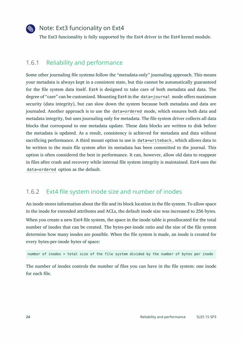
1.6.1 Reliability and performance
Some other journaling le systems follow the “metadata-only” journaling approach. This meansyour metadata is always kept in a consistent state, but this cannot be automatically guaranteedfor the le system data itself. Ext4 is designed to take care of both metadata and data. Thedegree of “care” can be customized. Mounting Ext4 in the data=journal mode offers maximumsecurity (data integrity), but can slow down the system because both metadata and data arejournaled. Another approach is to use the data=ordered mode, which ensures both data andmetadata integrity, but uses journaling only for metadata. The le system driver collects all datablocks that correspond to one metadata update. These data blocks are written to disk beforethe metadata is updated. As a result, consistency is achieved for metadata and data withoutsacrificing performance. A third mount option to use is data=writeback , which allows data tobe written to the main le system after its metadata has been committed to the journal. Thisoption is often considered the best in performance. It can, however, allow old data to reappearin les after crash and recovery while internal le system integrity is maintained. Ext4 uses thedata=ordered option as the default.
1.6.2 Ext4 file system inode size and number of inodes
An inode stores information about the le and its block location in the le system. To allow spacein the inode for extended attributes and ACLs, the default inode size was increased to 256 bytes.
When you create a new Ext4 le system, the space in the inode table is preallocated for the totalnumber of inodes that can be created. The bytes-per-inode ratio and the size of the le systemdetermine how many inodes are possible. When the le system is made, an inode is created forevery bytes-per-inode bytes of space:
number of inodes = total size of the file system divided by the number of bytes per inode
The number of inodes controls the number of les you can have in the le system: one inodefor each le.
24 Reliability and performance SLES 15 SP3

Important: Changing the inode size of an existing ext4 filesystem not possibleAfter the inodes are allocated, you cannot change the settings for the inode size or bytes-per-inode ratio. No new inodes are possible without re-creating the le system with dif-ferent settings, or unless the le system gets extended. When you exceed the maximumnumber of inodes, no new les can be created on the le system until some les aredeleted.
When you make a new Ext4 le system, you can specify the inode size and bytes-per-inode ratioto control inode space usage and the number of les possible on the le system. If the blockssize, inode size, and bytes-per-inode ratio values are not specified, the default values in the /etc/mked2fs.conf le are applied. For information, see the mke2fs.conf(5) man page.
Use the following guidelines:
Inode size: The default inode size is 256 bytes. Specify a value in bytes that is a powerof 2 and equal to 128 or larger in bytes and up to the block size, such as 128, 256, 512,and so on. Use 128 bytes only if you do not use extended attributes or ACLs on your Ext4le systems.
Bytes-per-inode ratio: The default bytes-per-inode ratio is 16384 bytes. Valid bytes-per-inode ratio values must be a power of 2 equal to 1024 or greater in bytes, such as 1024,2048, 4096, 8192, 16384, 32768, and so on. This value should not be smaller than theblock size of the le system, because the block size is the smallest chunk of space used tostore data. The default block size for the Ext4 le system is 4 KiB.In addition, consider the number of les and the size of les you need to store. For example,if your le system will have many small les, you can specify a smaller bytes-per-inode ra-tio, which increases the number of inodes. If your le system will have very large les, youcan specify a larger bytes-per-inode ratio, which reduces the number of possible inodes.Generally, it is better to have too many inodes than to run out of them. If you have toofew inodes and very small les, you could reach the maximum number of les on a diskthat is practically empty. If you have too many inodes and very large les, you might havefree space reported but be unable to use it because you cannot create new les in spacereserved for inodes.
25 Ext4 file system inode size and number of inodes SLES 15 SP3

Use any of the following methods to set the inode size and bytes-per-inode ratio:
Modifying the default settings for all new ext4 file systems: In a text editor, modify thedefaults section of the /etc/mke2fs.conf le to set the inode_size and inode_ra-tio to the desired default values. The values apply to all new Ext4 le systems. For ex-ample:
blocksize = 4096inode_size = 128inode_ratio = 8192
At the command line: Pass the inode size ( -I 128 ) and the bytes-per-inode ratio ( -i8192 ) to the mkfs.ext4(8) command or the mke2fs(8) command when you create anew ext4 le system. For example, use either of the following commands:
> sudo mkfs.ext4 -b 4096 -i 8092 -I 128 /dev/sda2> sudo mke2fs -t ext4 -b 4096 -i 8192 -I 128 /dev/sda2
During installation with YaST: Pass the inode size and bytes-per-inode ratio values whenyou create a new Ext4 le system during the installation. In the Expert Partitioner, select thepartition, click Edit. Under Formatting Options, select Format deviceExt4, then click Options.In the Format options dialog, select the desired values from the Block Size in Bytes, Bytes-per-inode, and Inode Size drop-down box.For example, select 4096 for the Block Size in Bytes drop-down box, select 8192 from theBytes per inode drop-down box, select 128 from the Inode Size drop-down box, then click OK.
26 Ext4 file system inode size and number of inodes SLES 15 SP3

1.6.3 Upgrading to Ext4
Important: Backup of dataBack up all data on the le system before performing any update of your le system.
PROCEDURE 1.3: UPGRADING TO EXT4
1. To upgrade from Ext2 or Ext3, you must enable the following:
FEATURES REQUIRED BY EXT4
extents
contiguous blocks on the hard disk that are used to keep les close together andprevent fragmentation
unint_bg
lazy inode table initialization
27 Upgrading to Ext4 SLES 15 SP3

dir_index
hashed b-tree lookups for large directores
on Ext2: as_journal
enable journalling on your Ext2 le system.
To enable the features, run:
on Ext3:
# tune2fs -O extents,uninit_bg,dir_index DEVICE_NAME
on Ext2:
# tune2fs -O extents,uninit_bg,dir_index,has_journal DEVICE_NAME
2. As root edit the /etc/fstab le: change the ext3 or ext2 record to ext4 . The changetakes effect after the next reboot.
3. To boot a le system that is setup on an ext4 parition, add the modules: ext4 and jbdin the initramfs . Open or create /etc/dracut.conf.d/filesystem.conf and add thefollowing line:
force_drivers+=" ext4 jbd"
You need to overwrite the existing dracut initramfs by running:
dracut -f
4. Reboot your system.
1.7 ReiserFSReiserFS support was completely removed with SUSE Linux Enterprise Server 15. To migrateyour existing partitions to Btrfs, refer to Section 1.2.3, “Migration from ReiserFS and ext file systems
to Btrfs”.
28 ReiserFS SLES 15 SP3

1.8 Other supported file systemsTable 1.1, “File system types in Linux” summarizes some other le systems supported by Linux. Theyare supported mainly to ensure compatibility and interchange of data with different kinds ofmedia or foreign operating systems.
TABLE 1.1: FILE SYSTEM TYPES IN LINUX
File System Type Description
cramfs Compressed ROM le system: A compressed read-only le system forROMs.
hpfs High Performance File System: The IBM OS/2 standard le system.Only supported in read-only mode.
iso9660 Standard le system on CD-ROMs.
minix This le system originated from academic projects on operating sys-tems and was the rst le system used in Linux. Today, it is used asa le system for floppy disks.
msdos fat , the le system originally used by DOS, is today used by vari-ous operating systems.
nfs Network File System: Here, data can be stored on any machine in anetwork and access might be granted via a network.
ntfs Windows NT le system; read-only.
exfat File system optimized for use with ash memory, such as USB ashdrives and SD cards.
smbfs Server Message Block is used by products such as Windows to enablele access over a network.
sysv Used on SCO Unix, Xenix, and Coherent (commercial Unix systemsfor PCs).
ufs Used by BSD, SunOS, and NextStep. Only supported in read-onlymode.
29 Other supported file systems SLES 15 SP3

File System Type Description
umsdos Unix on MS-DOS: Applied on top of a standard fat le system,achieves Unix functionality (permissions, links, long le names) bycreating special les.
vfat Virtual FAT: Extension of the fat le system (supports long lenames).
1.9 Large file support in LinuxOriginally, Linux supported a maximum le size of 2 GiB (231 bytes). Unless a le system comeswith large le support, the maximum le size on a 32-bit system is 2 GiB.
Currently, all of our standard le systems have LFS (large le support), which gives a maximumle size of 263 bytes in theory. Table 1.2, “Maximum sizes of files and file systems (on-disk format, 4
KiB block size)” offers an overview of the current on-disk format limitations of Linux les and lesystems. The numbers in the table assume that the le systems are using 4 KiB block size, whichis a common standard. When using different block sizes, the results are different. The maximumle sizes in Table 1.2, “Maximum sizes of files and file systems (on-disk format, 4 KiB block size)” can belarger than the le system's actual size when using sparse blocks.
Note: Binary multiplesIn this document: 1024 Bytes = 1 KiB; 1024 KiB = 1 MiB; 1024 MiB = 1 GiB; 1024 GiB= 1 TiB; 1024 TiB = 1 PiB; 1024 PiB = 1 EiB (see also NIST: Prefixes for Binary Multiples
(http://physics.nist.gov/cuu/Units/binary.html) .
TABLE 1.2: MAXIMUM SIZES OF FILES AND FILE SYSTEMS (ON-DISK FORMAT, 4 KIB BLOCK SIZE)
File System (4 KiB BlockSize)
Maximum File System Size Maximum File Size
Btrfs 16 EiB 16 EiB
Ext3 16 TiB 2 TiB
Ext4 1 EiB 16 TiB
30 Large file support in Linux SLES 15 SP3

File System (4 KiB BlockSize)
Maximum File System Size Maximum File Size
OCFS2 (a cluster-aware lesystem available in the HighAvailability Extension)
16 TiB 1 EiB
XFS 16 EiB 8 EiB
NFSv2 (client side) 8 EiB 2 GiB
NFSv3/NFSv4 (client side) 8 EiB 8 EiB
Important: LimitationsTable 1.2, “Maximum sizes of files and file systems (on-disk format, 4 KiB block size)” describesthe limitations regarding the on-disk format. The Linux kernel imposes its own limits onthe size of les and le systems handled by it. These are as follows:
File size
On 32-bit systems, les cannot exceed 2 TiB (241 bytes).
File system size
File systems can be up to 273 bytes in size. However, this limit is still out of reachfor the currently available hardware.
1.10 Linux kernel storage limitationsTable 1.3, “Storage limitations” summarizes the kernel limits for storage associated with SUSE LinuxEnterprise Server.
TABLE 1.3: STORAGE LIMITATIONS
Storage Feature Limitation
Maximum number of LUNs supported 16384 LUNs per target.
31 Linux kernel storage limitations SLES 15 SP3

Storage Feature Limitation
Maximum number of paths per single LUN No limit by default. Each path is treated as anormal LUN.
The actual limit is given by the number ofLUNs per target and the number of targetsper HBA (16777215 for a Fibre ChannelHBA).
Maximum number of HBAs Unlimited. The actual limit is determined bythe amount of PCI slots of the system.
Maximum number of paths with de-vice-mapper-multipath (in total) per operat-ing system
Approximately 1024. The actual numberdepends on the length of the device num-ber strings for each multipath device. Itis a compile-time variable within multi-path-tools, which can be raised if this limitposes a problem.
Maximum size per block device Up to 8 EiB.
1.11 Troubleshooting file systemsThis section describes some known issues and possible solutions for le systems.
1.11.1 Btrfs error: no space is left on device
The root ( / ) partition using the Btrfs le system stops accepting data. You receive the error“ No space left on device ”.
See the following sections for information about possible causes and prevention of this issue.
1.11.1.1 Disk space consumed by Snapper snapshots
If Snapper is running for the Btrfs le system, the “ No space left on device ” problem istypically caused by having too much data stored as snapshots on your system.
32 Troubleshooting file systems SLES 15 SP3

You can remove some snapshots from Snapper, however, the snapshots are not deleted imme-diately and might not free up as much space as you need.
To delete les from Snapper:
1. Open a terminal console.
2. At the command prompt, enter btrfs filesystem show , for example:
> sudo btrfs filesystem showLabel: none uuid: 40123456-cb2c-4678-8b3d-d014d1c78c78 Total devices 1 FS bytes used 20.00GB devid 1 size 20.00GB used 20.00GB path /dev/sda3
3. Enter
> sudo btrfs fi balance start MOUNTPOINT -dusage=5
This command attempts to relocate data in empty or near-empty data chunks, allowingthe space to be reclaimed and reassigned to metadata. This can take a while (many hoursfor 1 TB) although the system is otherwise usable during this time.
4. List the snapshots in Snapper. Enter
> sudo snapper -c root list
5. Delete one or more snapshots from Snapper. Enter
> sudo snapper -c root delete SNAPSHOT_NUMBER(S)
Ensure that you delete the oldest snapshots rst. The older a snapshot is, the more diskspace it occupies.
To help prevent this problem, you can change the Snapper cleanup algorithms. See Book “Admin-
istration Guide”, Chapter 7 “System recovery and snapshot management with Snapper”, Section 7.6.1.2
“Cleanup algorithms” for details. The configuration values controlling snapshot cleanup are EMP-TY_* , NUMBER_* , and TIMELINE_* .
If you use Snapper with Btrfs on the le system disk, it is advisable to reserve twice the amountof disk space than the standard storage proposal. The YaST Partitioner automatically proposestwice the standard disk space in the Btrfs storage proposal for the root le system.
33 Btrfs error: no space is left on device SLES 15 SP3

1.11.1.2 Disk space consumed by log, crash, and cache files
If the system disk is filling up with data, you can try deleting les from /var/log , /var/crash ,/var/lib/systemd/coredump and /var/cache .
The Btrfs root le system subvolumes /var/log , /var/crash and /var/cache can use allof the available disk space during normal operation, and cause a system malfunction. To helpavoid this situation, SUSE Linux Enterprise Server offers Btrfs quota support for subvolumes.See Section 1.2.5, “Btrfs quota support for subvolumes” for details.
On test and development machines, especially if you have frequent crashes of applications,you may also want to have a look at /var/lib/systemd/coredump where the core dumps arestored.
1.11.2 Freeing unused file system blocks
On solid-state drives (SSDs) and thinly provisioned volumes it is useful to trim blocks not in useby the le system. SUSE Linux Enterprise Server fully supports unmap or trim operations onall le systems supporting these methods.
The recommended way to trim a supported le system (except Btrfs) on SUSE Linux Enter-prise Server is to run /sbin/wiper.sh . Make sure to read /usr/share/doc/packages/hd-parm/README.wiper before running this script. For most desktop and server systems the suffi-cient trimming frequency is once a week. Mounting a le system with -o discard comes witha performance penalty and may negatively affect the lifetime of SSDs and is not recommended.
Warning: Do not use wiper.sh on BtrfsThe wiper.sh script trims read-write mounted Ext4 or XFS le systems, read-onlymounted/unmounted Ext2, Ext3, Ext4, or XFS le systems. Do not use wiper.sh on theBtrfs le system as it may damage your data. Instead, use /usr/share/btrfsmainte-nance/btrfs-trim.sh which is part of the btrfsmaintenance package.
34 Freeing unused file system blocks SLES 15 SP3
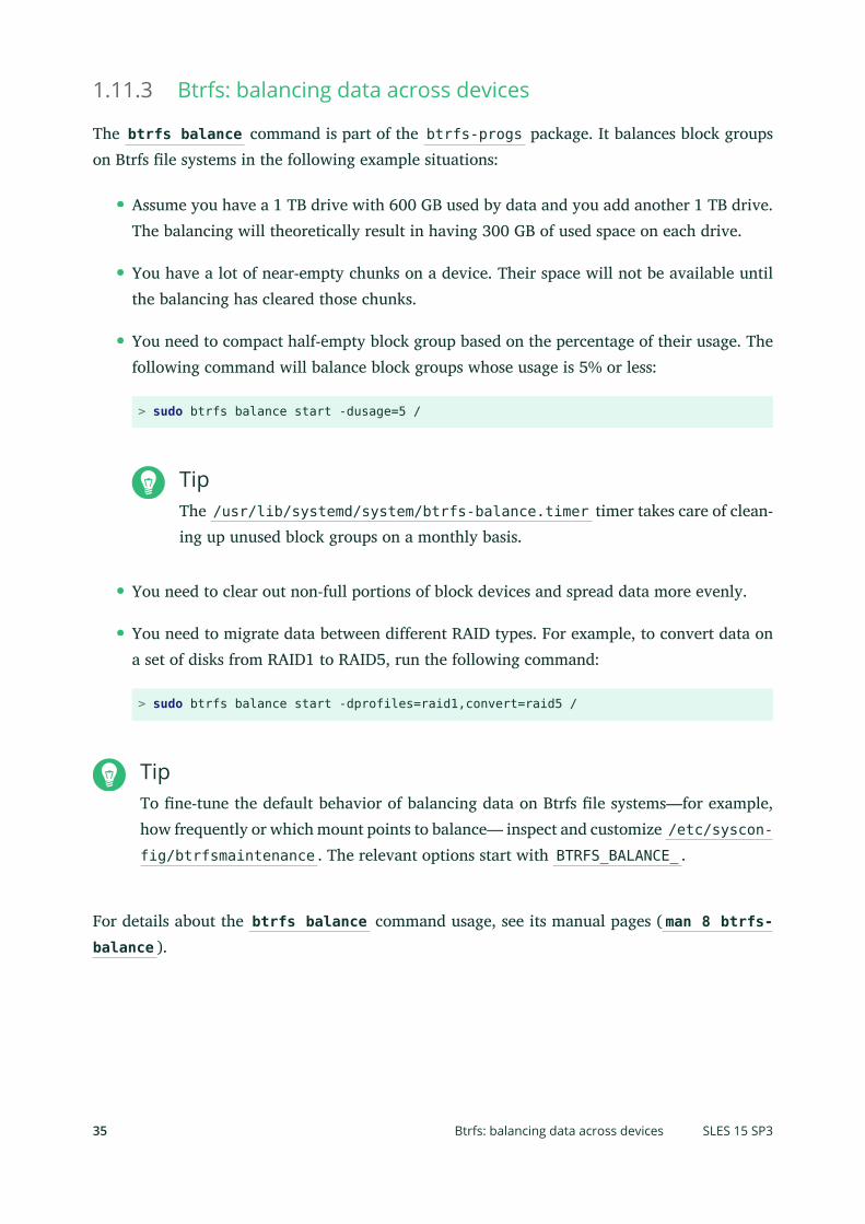
1.11.3 Btrfs: balancing data across devices
The btrfs balance command is part of the btrfs-progs package. It balances block groupson Btrfs le systems in the following example situations:
Assume you have a 1 TB drive with 600 GB used by data and you add another 1 TB drive.The balancing will theoretically result in having 300 GB of used space on each drive.
You have a lot of near-empty chunks on a device. Their space will not be available untilthe balancing has cleared those chunks.
You need to compact half-empty block group based on the percentage of their usage. Thefollowing command will balance block groups whose usage is 5% or less:
> sudo btrfs balance start -dusage=5 /
TipThe /usr/lib/systemd/system/btrfs-balance.timer timer takes care of clean-ing up unused block groups on a monthly basis.
You need to clear out non-full portions of block devices and spread data more evenly.
You need to migrate data between different RAID types. For example, to convert data ona set of disks from RAID1 to RAID5, run the following command:
> sudo btrfs balance start -dprofiles=raid1,convert=raid5 /
TipTo ne-tune the default behavior of balancing data on Btrfs le systems—for example,how frequently or which mount points to balance— inspect and customize /etc/syscon-fig/btrfsmaintenance . The relevant options start with BTRFS_BALANCE_ .
For details about the btrfs balance command usage, see its manual pages ( man 8 btrfs-balance ).
35 Btrfs: balancing data across devices SLES 15 SP3

1.11.4 No defragmentation on SSDs
Linux le systems contain mechanisms to avoid data fragmentation and usually it is not neces-sary to defragment. However, there are use cases, where data fragmentation cannot be avoidedand where defragmenting the hard disk significantly improves the performance.
This only applies to conventional hard disks. On solid state disks (SSDs) which use ash memoryto store data, the rmware provides an algorithm that determines to which chips the data iswritten. Data is usually spread all over the device. Therefore defragmenting an SSD does nothave the desired effect and will reduce the lifespan of an SSD by writing unnecessary data.
For the reasons mentioned above, SUSE explicitly recommends not to defragment SSDs. Somevendors also warn about defragmenting solid state disks. This includes, but it is not limited tothe following:
HPE 3PAR StoreServ All-Flash
HPE 3PAR StoreServ Converged Flash
1.12 More informationEach of the le system projects described above maintains its own home page on which to ndmailing list information, further documentation, and FAQs:
The Btrfs Wiki on Kernel.org: https://btrfs.wiki.kernel.org/
E2fsprogs: Ext2/3/4 File System Utilities: http://e2fsprogs.sourceforge.net/
The OCFS2 Project: https://oss.oracle.com/projects/ocfs2/
An in-depth comparison of le systems (not only Linux le systems) is available fromthe Wikipedia project in Comparison of File Systems (http://en.wikipedia.org/wiki/Compari-
son_of_file_systems#Comparison ).
36 No defragmentation on SSDs SLES 15 SP3

2 Resizing file systems
Resizing le systems—not to be confused with resizing partitions or volumes—can be used tomake space available on physical volumes or to use additional space available on a physicalvolume.
2.1 Use casesIt is strongly recommended to use the YaST Partitioner to resize partitions or logical volumes.When doing so, the le system will automatically be adjusted to the new size of the partitionor volume. However, there are some cases where you need to resize the le system manually,because they are not supported by YaST:
After having resized a virtual disk of a VM Guest.
After having resized a volume from a network-attached storage.
After having manually resized partitions (for example by using fdisk or parted ) orlogical volumes (for example by using lvresize ).
When wanting to shrink Btrfs le systems (as of SUSE Linux Enterprise Server 12, YaSTonly supports growing Btrfs le systems).
2.2 Guidelines for resizingResizing any le system involves some risks that can potentially result in losing data.
Warning: Back up your dataTo avoid data loss, ensure that you back up your data before you begin any resizing task.
Consider the following guidelines when planning to resize a le system.
37 Use cases SLES 15 SP3

2.2.1 File systems that support resizing
The le system must support resizing to take advantage of increases in available space for thevolume. In SUSE Linux Enterprise Server, le system resizing utilities are available for le sys-tems Ext2, Ext3, and Ext4. The utilities support increasing and decreasing the size as follows:
TABLE 2.1: FILE SYSTEM SUPPORT FOR RESIZING
File System Utility Increase Size(Grow)
Decrease Size(Shrink)
Btrfs btrfs filesystemresize
Online Online
XFS xfs_growfs Online Not supported
Ext2 resize2fs Online or offline Offline only
Ext3 resize2fs Online or offline Offline only
Ext4 resize2fs Online or offline Offline only
2.2.2 Increasing the size of a file system
You can grow a le system to the maximum space available on the device, or specify an exactsize. Ensure that you grow the size of the device or logical volume before you attempt to increasethe size of the le system.
When specifying an exact size for the le system, ensure that the new size satisfies the followingconditions:
The new size must be greater than the size of the existing data; otherwise, data loss occurs.
The new size must be equal to or less than the current device size because the le systemsize cannot extend beyond the space available.
38 File systems that support resizing SLES 15 SP3

2.2.3 Decreasing the size of a file system
When decreasing the size of the le system on a device, ensure that the new size satisfies thefollowing conditions:
The new size must be greater than the size of the existing data; otherwise, data loss occurs.
The new size must be equal to or less than the current device size because the le systemsize cannot extend beyond the space available.
If you plan to also decrease the size of the logical volume that holds the le system, ensure thatyou decrease the size of the le system before you attempt to decrease the size of the deviceor logical volume.
Important: XFSDecreasing the size of a le system formatted with XFS is not possible, since such a featureis not supported by XFS.
2.3 Changing the size of a Btrfs file systemThe size of a Btrfs le system can be changed by using the btrfs filesystem resize commandwhen the le system is mounted. Increasing and decreasing the size are both supported whilethe le system is mounted.
1. Open a terminal console.
2. Make sure the le system you want to change is mounted.
3. Change the size of the le system using the btrfs filesystem resize command withone of the following methods:
To extend the le system size to the maximum available size of the device, enter
> sudo btrfs filesystem resize max /mnt
To extend the le system to a specific size, enter
> sudo btrfs filesystem resize SIZE /mnt
39 Decreasing the size of a file system SLES 15 SP3

Replace SIZE with the desired size in bytes. You can also specify units on the value,such as 50000K (kilobytes), 250M (megabytes), or 2G (gigabytes). Alternatively, youcan specify an increase or decrease to the current size by prefixing the value with aplus ( + ) or a minus ( - ) sign, respectively:
> sudo btrfs filesystem resize +SIZE /mntsudo btrfs filesystem resize -SIZE /mnt
4. Check the effect of the resize on the mounted le system by entering
> df -h
The Disk Free ( df ) command shows the total size of the disk, the number of blocks used,and the number of blocks available on the le system. The -h option prints sizes in hu-man-readable format, such as 1K, 234M, or 2G.
2.4 Changing the size of an XFS file systemThe size of an XFS le system can be increased by using the xfs_growfs command when thele system is mounted. Reducing the size of an XFS le system is not possible.
1. Open a terminal console.
2. Make sure the le system you want to change is mounted.
3. Increase the size of the le system using the xfs_growfs command. The following ex-ample expands the size of the le system to the maximum value available. See man 8xfs_growfs for more options.
> sudo xfs_growfs -d /mnt
4. Check the effect of the resize on the mounted le system by entering
> df -h
The Disk Free ( df ) command shows the total size of the disk, the number of blocks used,and the number of blocks available on the le system. The -h option prints sizes in hu-man-readable format, such as 1K, 234M, or 2G.
40 Changing the size of an XFS file system SLES 15 SP3

2.5 Changing the size of an ext2, ext3, or ext4 filesystemThe size of Ext2, Ext3, and Ext4 le systems can be increased by using the resize2fs command,regardless of whether the respective partition is mounted or not. To decrease the size of an Extle system it needs to be unmounted.
1. Open a terminal console.
2. If the le system size should be decreased, unmount it.
3. Change the size of the le system using one of the following methods:
To extend the le system size to the maximum available size of the device called /dev/sda1 , enter
> sudo resize2fs /dev/sda1
If a size parameter is not specified, the size defaults to the size of the partition.
To change the le system to a specific size, enter
> sudo resize2fs /dev/sda1 SIZE
The SIZE parameter specifies the requested new size of the le system. If no units arespecified, the unit of the size parameter is the block size of the le system. Optionally,the size parameter can be suffixed by one of the following unit designations: s for512 byte sectors; K for kilobytes (1 kilobyte is 1024 bytes); M for megabytes; orG for gigabytes.
Wait until the resizing is completed before continuing.
4. If the le system is not mounted, mount it now.
5. Check the effect of the resize on the mounted le system by entering
> df -h
The Disk Free ( df ) command shows the total size of the disk, the number of blocks used,and the number of blocks available on the le system. The -h option prints sizes in hu-man-readable format, such as 1K, 234M, or 2G.
41 Changing the size of an ext2, ext3, or ext4 file system SLES 15 SP3

3 Mounting storage devices
This section gives an overview which device identificators are used during mounting of devices,and provides details about mounting network storages.
3.1 Understanding UUIDsA UUID (Universally Unique Identifier) is a 128-bit number for a le system that is unique onboth the local system and across other systems. It is randomly generated with system hardwareinformation and time stamps as part of its seed. UUIDs are commonly used to uniquely tagdevices.
Using non-persistent “traditional” device names such as /dev/sda1 may render the systemunbootable when adding storage. For example, if root ( / ) is assigned to /dev/sda1 , it mightbe reassigned to /dev/sdg1 after a SAN has been attached or additional hard disks have beenapplied to the system. In this case the boot loader configuration and the /etc/fstab le needto be adjusted, otherwise the system will no longer boot.
By default UUID are used in the boot loader and /etc/fstab les for the boot device. The UUIDis a property of the le system and can change if you reformat the drive. Other alternatives tousing UUIDs of device names would be to identify devices by ID or label.
You can also use the UUID as criterion for assembling and activating software RAID devices.When a RAID is created, the md driver generates a UUID for the device, and stores the valuein the md superblock.
You can nd the UUID for any block device in the /dev/disk/by-uuid directory. For example,a UUID entry looks like this:
> ls -og /dev/disk/by-uuid/lrwxrwxrwx 1 10 Dec 5 07:48 e014e482-1c2d-4d09-84ec-61b3aefde77a -> ../../sda1
3.2 Persistent device names with udevStarting with Linux kernel 2.6, udev provides a user space solution for the dynamic /devdirectory, with persistent device naming. As part of the hotplug system, udev is executed if adevice is added to or removed from the system.
42 Understanding UUIDs SLES 15 SP3

A list of rules is used to match against specific device attributes. The udev rules infrastructure(defined in the /etc/udev/rules.d directory) provides stable names for all disk devices, re-gardless of their order of recognition or the connection used for the device. The udev toolsexamine every appropriate block device that the kernel creates to apply naming rules based oncertain buses, drive types, or le systems. For information about how to define your own rulesfor udev , see Writing udev Rules (http://reactivated.net/writing_udev_rules.html) .
Along with the dynamic kernel-provided device node name, udev maintains classes of persistentsymbolic links pointing to the device in the /dev/disk directory, which is further categorizedby the by-id , by-label , by-path , and by-uuid subdirectories.
Note: UUID generatorsOther programs besides udev , such as LVM or md , might also generate UUIDs, but theyare not listed in /dev/disk .
For more information about using udev for managing devices, see Book “Administration Guide”,
Chapter 24 “Dynamic kernel device management with udev”.
For more information about udev commands, see man 7 udev .
3.3 Mounting network storage devicesSome types of storage devices require network to be configured and available before sys-temd.mount starts to mount the devices. To postpone mounting of these types of devices, addthe _netdev option to the /etc/fstab le for each particular network storage device. Anexample follows:
UUID=83df497d-bd6d-48a3-9275-37c0e3c8dc74 /root ntfs defaults,_netdev 0 0
43 Mounting network storage devices SLES 15 SP3

4 Multi-tier caching for block device operations
A multi-tier cache is a replicated/distributed cache that consists of at least two tiers: one isrepresented by slower but cheaper rotational block devices (hard disks), while the other is moreexpensive but performs faster data operations (for example SSD ash disks).
SUSE Linux Enterprise Server implements two different solutions for caching between ash androtational devices: bcache and lvmcache .
4.1 General terminologyThis section explains several terms often used when describing cache related features:
Migration
Movement of the primary copy of a logical block from one device to the other.
Promotion
Migration from the slow device to the fast device.
Demotion
Migration from the fast device to the slow device.
Origin device
The big and slower block device. It always contains a copy of the logical block, which maybe out of date or kept in synchronization with the copy on the cache device (dependingon policy).
Cache device
The small and faster block device.
Metadata device
A small device that records which blocks are in the cache, which are dirty, and extra hintsfor use by the policy object. This information could be put on the cache device as well,but having it separate allows the volume manager to configure it differently, for exampleas a mirror for extra robustness. The metadata device may only be used by a single cachedevice.
Dirty block
44 General terminology SLES 15 SP3

If some process writes to a block of data which is placed in the cache, the cached blockis marked as dirty because it was overwritten in the cache and needs to be written backto the original device.
Cache miss
A request for I/O operations is pointed to the cached device's cache rst. If it cannot ndthe requested values, it looks in the device itself, which is slow. This is called a cache miss.
Cache hit
When a requested value is found in the cached device's cache, it is served fast. This iscalled a cache hit.
Cold cache
Cache that holds no values (is empty) and causes cache misses. As the cached block deviceoperations progress, it gets lled with data and becomes warm.
Warm cache
Cache that already holds some values and is likely to result in cache hits.
4.2 Caching modesFollowing are the basic caching modes that multi-tier caches use: write-back, write-through, write-around and pass-through.
write-back
Data written to a block that is cached go to the cache only, and the block is marked dirty.This is the default caching mode.
write-through
Writing to a cached block will not complete until it has hit both the origin and cachedevices. Clean blocks remain clean with write-through cache.
write-around
A similar technique to write-through cache, but write I/O is written directly to a permanentstorage, bypassing the cache. This can prevent the cache being flooded with write I/O thatwill not subsequently be re-read, but the disadvantage is that a read request for recentlywritten data will create a 'cache miss' and needs to be read from slower bulk storage andexperience higher latency.
pass-through
45 Caching modes SLES 15 SP3
To enable the pass-through mode, the cache needs to be clean. Reading is served from theorigin device bypassing the cache. Writing is forwarded to the origin device and 'invali-dates' the cache block. Pass-through allows a cache device activation without having tocare about data coherency, which is maintained. The cache will gradually become cold aswriting takes place. If you can verify the coherency of the cache later, or establish it byusing the invalidate_cblocks message, you can switch the cache device to write-throughor write-back mode while it is still warm. Otherwise, you can discard the cache contentsbefore switching to the desired caching mode.
4.3 bcachebcache is a Linux kernel block layer cache. It allows one or more fast disk drives (such as SSDs)to act as a cache for one or more slower hard disks. bcache supports write-through and write-back, and is independent of the le system used. By default it caches random reads and writesonly, which SSDs excel at. It is suitable for desktops, servers, and high end storage arrays as well.
4.3.1 Main features
A single cache device can be used to cache an arbitrary number of backing devices. Backingdevices can be attached and detached at runtime, while mounted and in use.
Recovers from unclean shutdowns—writes are not completed until the cache is consistentwith regard to the backing device.
Throttles traffic to the SSD if it becomes congested.
Highly efficient write-back implementation. Dirty data is always written out in sorted or-der.
Stable and reliable—in production use.
4.3.2 Setting up a bcache device
This section describes steps to set up and manage a bcache device.
1. Install the bcache-tools package:
> sudo zypper in bcache-tools
46 bcache SLES 15 SP3
2. Create a backing device (typically a mechanical drive). The backing device can be a wholedevice, a partition, or any other standard block device.
> sudo make-bcache -B /dev/sdb
3. Create a cache device (typically an SSD disk).
> sudo make-bcache -C /dev/sdc
In this example, the default block and bucket sizes of 512 B and 128 KB are used. Theblock size should match the backing device's sector size which will usually be either 512or 4k. The bucket size should match the erase block size of the caching device with theintention of reducing write amplification. For example, using a hard disk with 4k sectorsand an SSD with an erase block size of 2 MB this command would look as follows:
sudo make-bcache --block 4k --bucket 2M -C /dev/sdc
Tip: Multi-device supportmake-bcache can prepare and register multiple backing devices and a cache deviceat the same time. In this case you do not need to manually attach the cache deviceto the backing device afterward:
> sudo make-bcache -B /dev/sda /dev/sdb -C /dev/sdc
4. bcache devices show up as
/dev/bcacheN
and as
/dev/bcache/by-uuid/UUID/dev/bcache/by-label/LABEL
You can normally format and mount bcache devices as usual:
> sudo mkfs.ext4 /dev/bcache0> sudo mount /dev/bcache0 /mnt
You can control bcache devices through sysfs at /sys/block/bcacheN/bcache .
47 Setting up a bcache device SLES 15 SP3

5. After both the cache and backing devices are registered, you need to attach the backingdevice to the related cache set to enable caching:
> echo CACHE_SET_UUID > /sys/block/bcache0/bcache/attach
where CACHE_SET_UUID is found in /sys/fs/bcache .
6. By default bcache uses a pass-through caching mode. To change it to for example write-back, run
> echo writeback > /sys/block/bcache0/bcache/cache_mode
4.3.3 bcache configuration using sysfs
bcache devices use the sysfs interface to store their runtime configuration values. This wayyou can change bcache backing and cache disks' behavior or see their usage statistics.
For the complete list of bcache sysfs parameters, see the contents of the /usr/src/lin-ux/Documentation/bcache.txt le, mainly the SYSFS - BACKING DEVICE , SYSFS - BACK-ING DEVICE STATS , and SYSFS - CACHE DEVICE sections.
4.4 lvmcachelvmcache is a caching mechanism consisting of logical volumes (LVs). It uses the dm-cachekernel driver and supports write-through (default) and write-back caching modes. lvmcacheimproves performance of a large and slow LV by dynamically migrating some of its data to afaster and smaller LV. For more information on LVM, see Part II, “Logical volumes (LVM)”.
LVM refers to the small, fast LV as a cache pool LV. The large, slow LV is called the origin LV.Because of requirements from dm-cache, LVM further splits the cache pool LV into two devices:the cache data LV and cache metadata LV. The cache data LV is where copies of data blocksare kept from the origin LV to increase speed. The cache metadata LV holds the accountinginformation that specifies where data blocks are stored.
4.4.1 Configuring lvmcache
This section describes steps to create and configure LVM based caching.
48 bcache configuration using sysfs SLES 15 SP3

1. Create the origin LV. Create a new LV or use an existing LV to become the origin LV:
> sudo lvcreate -n ORIGIN_LV -L 100G vg /dev/SLOW_DEV
2. Create the cache data LV. This LV will hold data blocks from the origin LV. The size of thisLV is the size of the cache and will be reported as the size of the cache pool LV.
> sudo lvcreate -n CACHE_DATA_LV -L 10G vg /dev/FAST
3. Create the cache metadata LV. This LV will hold cache pool metadata. The size of this LVshould be approximately 1000 times smaller than the cache data LV, with a minimumsize of 8MB.
> sudo lvcreate -n CACHE_METADATA_LV -L 12M vg /dev/FAST
List the volumes you have created so far:
> sudo lvs -a vgLV VG Attr LSize Pool Origincache_data_lv vg -wi-a----- 10.00gcache_metadata_lv vg -wi-a----- 12.00morigin_lv vg -wi-a----- 100.00g
4. Create a cache pool LV. Combine the data and metadata LVs into a cache pool LV. You canset the cache pool LV's behavior at the same time.CACHE_POOL_LV takes the name of CACHE_DATA_LV .CACHE_DATA_LV is renamed to CACHE_DATA_LV _cdata and becomes hidden.CACHE_META_LV is renamed to CACHE_DATA_LV _cmeta and becomes hidden.
> sudo lvconvert --type cache-pool \ --poolmetadata vg/cache_metadata_lv vg/cache_data_lv
> sudo lvs -a vgLV VG Attr LSize Pool Origincache_data_lv vg Cwi---C--- 10.00g[cache_data_lv_cdata] vg Cwi------- 10.00g[cache_data_lv_cmeta] vg ewi------- 12.00morigin_lv vg -wi-a----- 100.00g
5. Create a cache LV. Create a cache LV by linking the cache pool LV to the origin LV.The user accessible cache LV takes the name of the origin LV, while the origin LV becomesa hidden LV renamed to ORIGIN_LV _corig.CacheLV takes the name of ORIGIN_LV .
49 Configuring lvmcache SLES 15 SP3

ORIGIN_LV is renamed to ORIGIN_LV _corig and becomes hidden.
> sudo lvconvert --type cache --cachepool vg/cache_data_lv vg/origin_lv
> sudo lvs -a vgLV VG Attr LSize Pool Origincache_data_lv vg Cwi---C--- 10.00g[cache_data_lv_cdata] vg Cwi-ao---- 10.00g[cache_data_lv_cmeta] vg ewi-ao---- 12.00morigin_lv vg Cwi-a-C--- 100.00g cache_data_lv [origin_lv_corig][origin_lv_corig] vg -wi-ao---- 100.00g
4.4.2 Removing a cache pool
There are several ways to turn o the LV cache.
4.4.2.1 Detach a cache pool LV from a cache LV
You can disconnect a cache pool LV from a cache LV, leaving an unused cache pool LV and anuncached origin LV. Data are written back from the cache pool to the origin LV when necessary.
> sudo lvconvert --splitcache vg/origin_lv
4.4.2.2 Removing a cache pool LV without removing its origin LV
This writes back data from the cache pool to the origin LV when necessary, then removes thecache pool LV, leaving the uncached origin LV.
> sudo lvremove vg/cache_data_lv
An alternative command that also disconnects the cache pool from the cache LV, and deletesthe cache pool:
> sudo lvconvert --uncache vg/origin_lv
4.4.2.3 Removing both the origin LV and the cache pool LV
Removing a cache LV removes both the origin LV and the linked cache pool LV.
50 Removing a cache pool SLES 15 SP3

> sudo lvremove vg/origin_lv
4.4.2.4 More information
You can nd more lvmcache related topics, such as supported cache modes, redundant sub-logical volumes, cache policy, or converting existing LVs to cache types, in the lvmcache man-ual page ( man 7 lvmcache ).
51 Removing a cache pool SLES 15 SP3

II Logical volumes (LVM)
5 LVM configuration 53
6 LVM volume snapshots 82

5 LVM configuration
This chapter describes the principles behind Logical Volume Manager (LVM) and itsbasic features that make it useful under many circumstances. The YaST LVM config-uration can be reached from the YaST Expert Partitioner. This partitioning tool en-ables you to edit and delete existing partitions and create new ones that should beused with LVM.
Warning: RisksUsing LVM might be associated with increased risk, such as data loss. Risks also includeapplication crashes, power failures, and faulty commands. Save your data before imple-menting LVM or reconfiguring volumes. Never work without a backup.
5.1 Understanding the logical volume managerLVM enables flexible distribution of hard disk space over several physical volumes (hard disks,partitions, LUNs). It was developed because the need to change the segmentation of hard diskspace might arise only after the initial partitioning has already been done during installation.Because it is difficult to modify partitions on a running system, LVM provides a virtual pool(volume group or VG) of storage space from which logical volumes (LVs) can be created asneeded. The operating system accesses these LVs instead of the physical partitions. Volumegroups can span more than one disk, so that several disks or parts of them can constitute onesingle VG. In this way, LVM provides a kind of abstraction from the physical disk space thatallows its segmentation to be changed in a much easier and safer way than through physicalrepartitioning.
Figure 5.1, “Physical partitioning versus LVM” compares physical partitioning (left) with LVM seg-mentation (right). On the left side, one single disk has been divided into three physical partitions(PART), each with a mount point (MP) assigned so that the operating system can access them.On the right side, two disks have been divided into two and three physical partitions each. TwoLVM volume groups (VG 1 and VG 2) have been defined. VG 1 contains two partitions fromDISK 1 and one from DISK 2. VG 2 contains the remaining two partitions from DISK 2.
53 Understanding the logical volume manager SLES 15 SP3

DISK
PART PART PART
MP MP MP
DISK 1 DISK 2
MP MP MP MP
PART PART PART PART PART
VG 1 VG 2
LV 1 LV 2 LV 3 LV4
FIGURE 5.1: PHYSICAL PARTITIONING VERSUS LVM
In LVM, the physical disk partitions that are incorporated in a volume group are called physicalvolumes (PVs). Within the volume groups in Figure 5.1, “Physical partitioning versus LVM”, fourlogical volumes (LV 1 through LV 4) have been defined, which can be used by the operatingsystem via the associated mount points (MP). The border between different logical volumes neednot be aligned with any partition border. See the border between LV 1 and LV 2 in this example.
LVM features:
Several hard disks or partitions can be combined in a large logical volume.
Provided the configuration is suitable, an LV (such as /usr ) can be enlarged when thefree space is exhausted.
Using LVM, it is possible to add hard disks or LVs in a running system. However, thisrequires hotpluggable hardware that is capable of such actions.
It is possible to activate a striping mode that distributes the data stream of a logical volumeover several physical volumes. If these physical volumes reside on different disks, this canimprove the reading and writing performance like RAID 0.
The snapshot feature enables consistent backups (especially for servers) in the runningsystem.
Note: LVM and RAIDEven though LVM also supports RAID levels 0, 1, 4, 5 and 6, we recommend using mdraid(see Chapter 7, Software RAID configuration). However, LVM works ne with RAID 0 and 1,as RAID 0 is similar to common logical volume management (individual logical blocks are
54 Understanding the logical volume manager SLES 15 SP3

mapped onto blocks on the physical devices). LVM used on top of RAID 1 can keep trackof mirror synchronization and is fully able to manage the synchronization process. Withhigher RAID levels you need a management daemon that monitors the states of attacheddisks and can inform administrators if there is a problem in the disk array. LVM includessuch a daemon, but in exceptional situations such as a device failure, the daemon doesnot work properly.
Warning: IBM Z: LVM root file systemIf you configure the system with a root le system on LVM or software RAID array, youmust place /boot on a separate, non-LVM or non-RAID partition, otherwise the systemwill fail to boot. The recommended size for such a partition is 500 MB and the recom-mended le system is Ext4.
With these features, using LVM already makes sense for heavily-used home PCs or small servers.If you have a growing data stock, as in the case of databases, music archives, or user directo-ries, LVM is especially useful. It allows le systems that are larger than the physical hard disk.However, keep in mind that working with LVM is different from working with conventionalpartitions.
You can manage new or existing LVM storage objects by using the YaST Partitioner. Instructionsand further information about configuring LVM are available in the official LVM HOWTO (http://
tldp.org/HOWTO/LVM-HOWTO/) .
5.2 Creating volume groupsAn LVM volume group (VG) organizes the Linux LVM partitions into a logical pool of space. Youcan carve out logical volumes from the available space in the group. The Linux LVM partitionsin a group can be on the same or different disks. You can add partitions or entire disks to expandthe size of the group.
To use an entire disk, it must not contain any partitions. When using partitions, they must notbe mounted. YaST will automatically change their partition type to 0x8E Linux LVM whenadding them to a VG.
1. Launch YaST and open the Partitioner.
55 Creating volume groups SLES 15 SP3
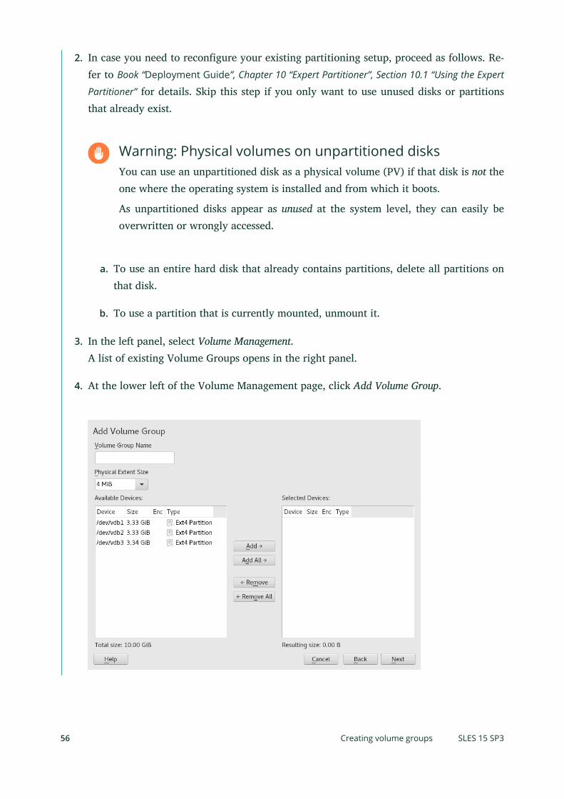
2. In case you need to reconfigure your existing partitioning setup, proceed as follows. Re-fer to Book “Deployment Guide”, Chapter 10 “Expert Partitioner”, Section 10.1 “Using the Expert
Partitioner” for details. Skip this step if you only want to use unused disks or partitionsthat already exist.
Warning: Physical volumes on unpartitioned disksYou can use an unpartitioned disk as a physical volume (PV) if that disk is not theone where the operating system is installed and from which it boots.
As unpartitioned disks appear as unused at the system level, they can easily beoverwritten or wrongly accessed.
a. To use an entire hard disk that already contains partitions, delete all partitions onthat disk.
b. To use a partition that is currently mounted, unmount it.
3. In the left panel, select Volume Management.A list of existing Volume Groups opens in the right panel.
4. At the lower left of the Volume Management page, click Add Volume Group.
56 Creating volume groups SLES 15 SP3

5. Define the volume group as follows:
a. Specify the Volume Group Name.If you are creating a volume group at install time, the name system is suggested fora volume group that will contain the SUSE Linux Enterprise Server system les.
b. Specify the Physical Extent Size.The Physical Extent Size defines the size of a physical block in the volume group. Allthe disk space in a volume group is handled in chunks of this size. Values can befrom 1 KB to 16 GB in powers of 2. This value is normally set to 4 MB.In LVM1, a 4 MB physical extent allowed a maximum LV size of 256 GB becauseit supports only up to 65534 extents per LV. LVM2, which is used on SUSE LinuxEnterprise Server, does not restrict the number of physical extents. Having manyextents has no impact on I/O performance to the logical volume, but it slows downthe LVM tools.
Important: Physical extent sizesDifferent physical extent sizes should not be mixed in a single VG. The extentshould not be modified after the initial setup.
c. In the Available Physical Volumes list, select the Linux LVM partitions that you want tomake part of this volume group, then click Add to move them to the Selected PhysicalVolumes list.
d. Click Finish.The new group appears in the Volume Groups list.
6. On the Volume Management page, click Next, verify that the new volume group is listed,then click Finish.
7. To check which physical devices are part of the volume group, open the YaST Partitionerat any time in the running system and click Volume Management Edit Physical Devices.Leave this screen with Abort.
57 Creating volume groups SLES 15 SP3

FIGURE 5.2: PHYSICAL VOLUMES IN THE VOLUME GROUP NAMED DATA
5.3 Creating logical volumesA logical volume provides a pool of space similar to what a hard disk does. To make this spaceusable, you need to define logical volumes. A logical volume is similar to a regular partition—you can format and mount it.
Use The YaST Partitioner to create logical volumes from an existing volume group. Assign at leastone logical volume to each volume group. You can create new logical volumes as needed untilall free space in the volume group has been exhausted. An LVM logical volume can optionally bethinly provisioned, allowing you to create logical volumes with sizes that overbook the availablefree space (see Section 5.3.1, “Thinly provisioned logical volumes” for more information).
Normal volume: (Default) The volume’s space is allocated immediately.
Thin pool: The logical volume is a pool of space that is reserved for use with thin volumes.The thin volumes can allocate their needed space from it on demand.
58 Creating logical volumes SLES 15 SP3

Thin volume: The volume is created as a sparse volume. The volume allocates neededspace on demand from a thin pool.
Mirrored volume: The volume is created with a defined count of mirrors.
PROCEDURE 5.1: SETTING UP A LOGICAL VOLUME
1. Launch YaST and open the Partitioner.
2. In the left panel, select Volume Management. A list of existing Volume Groups opens inthe right panel.
3. Select the volume group in which you want to create the volume and choose Logical Vol-umes Add Logical Volume.
4. Provide a Name for the volume and choose Normal Volume (refer to Section 5.3.1, “Thinly
provisioned logical volumes” for setting up thinly provisioned volumes). Proceed with Next.
5. Specify the size of the volume and whether to use multiple stripes.Using a striped volume, the data will be distributed among several physical volumes. Ifthese physical volumes reside on different hard disks, this generally results in a betterreading and writing performance (like RAID 0). The maximum number of available stripesis equal to the number of physical volumes. The default ( 1 is to not use multiple stripes.
59 Creating logical volumes SLES 15 SP3

6. Choose a Role for the volume. Your choice here only affects the default values for theupcoming dialog. They can be changed in the next step. If in doubt, choose Raw Volume(Unformatted).
60 Creating logical volumes SLES 15 SP3

7. Under Formatting Options, select Format Partition, then select the File system. The contentof the Options menu depends on the le system. Usually there is no need to change thedefaults.Under Mounting Options, select Mount partition, then select the mount point. Click FstabOptions to add special mounting options for the volume.
8. Click Finish.
9. Click Next, verify that the changes are listed, then click Finish.
5.3.1 Thinly provisioned logical volumes
An LVM logical volume can optionally be thinly provisioned. Thin provisioning allows you tocreate logical volumes with sizes that overbook the available free space. You create a thin poolthat contains unused space reserved for use with an arbitrary number of thin volumes. A thinvolume is created as a sparse volume and space is allocated from a thin pool as needed. The thinpool can be expanded dynamically when needed for cost-effective allocation of storage space.Thinly provisioned volumes also support snapshots which can be managed with Snapper—seeBook “Administration Guide”, Chapter 7 “System recovery and snapshot management with Snapper” formore information.
To set up a thinly provisioned logical volume, proceed as described in Procedure 5.1, “Setting up a
logical volume”. When it comes to choosing the volume type, do not choose Normal Volume, butrather Thin Volume or Thin Pool.
Thin pool
The logical volume is a pool of space that is reserved for use with thin volumes. The thinvolumes can allocate their needed space from it on demand.
Thin volume
The volume is created as a sparse volume. The volume allocates needed space on demandfrom a thin pool.
Important: Thinly provisioned volumes in a clusterTo use thinly provisioned volumes in a cluster, the thin pool and the thin volumes thatuse it must be managed in a single cluster resource. This allows the thin volumes and thinpool to always be mounted exclusively on the same node.
61 Thinly provisioned logical volumes SLES 15 SP3
5.3.2 Creating mirrored volumes
A logical volume can be created with several mirrors. LVM ensures that data written to anunderlying physical volume is mirrored onto a different physical volume. Thus even though aphysical volume crashes, you can still access the data on the logical volume. LVM also keepsa log le to manage the synchronization process. The log contains information about whichvolume regions are currently undergoing synchronization with mirrors. By default the log isstored on disk and if possible on a different disk than are the mirrors. But you may specify adifferent location for the log, for example volatile memory.
Currently there are two types of mirror implementation available: "normal" (non-raid) mirrorlogical volumes and raid1 logical volumes.
After you create mirrored logical volumes, you can perform standard operations with mirroredlogical volumes like activating, extending, and removing.
5.3.2.1 Setting up mirrored non-RAID logical volumes
To create a mirrored volume use the lvcreate command. The following example creates a500 GB logical volume with two mirrors called lv1, which uses a volume group vg1.
> sudo lvcreate -L 500G -m 2 -n lv1 vg1
Such a logical volume is a linear volume (without striping) that provides three copies of thele system. The m option specifies the count of mirrors. The L option specifies the size of thelogical volumes.
The logical volume is divided into regions of the 512 KB default size. If you need a differentsize of regions, use the -R option followed by the desired region size in megabytes. Or you canconfigure the preferred region size by editing the mirror_region_size option in the lvm.confle.
5.3.2.2 Setting up raid1 logical volumes
As LVM supports RAID you can implement mirroring by using RAID1. Such implementationprovides the following advantages compared to the non-raid mirrors:
LVM maintains a fully redundant bitmap area for each mirror image, which increases itsfault handling capabilities.
Mirror images can be temporarily split from the array and then merged back.
62 Creating mirrored volumes SLES 15 SP3

The array can handle transient failures.
The LVM RAID 1 implementation supports snapshots.
On the other hand, this type of mirroring implementation does not enable to create a logicalvolume in a clustered volume group.
To create a mirror volume by using RAID, issue the command
> sudo lvcreate --type raid1 -m 1 -L 1G -n lv1 vg1
where the options/parameters have the following meanings:
--type - you need to specify raid1 , otherwise the command uses the implicit segmenttype mirror and creates a non-raid mirror.
-m - specifies the count of mirrors.
-L - specifies the size of the logical volume.
-n - by using this option you specify a name of the logical volume.
vg1 - is a name of the volume group used by the logical volume.
LVM creates a logical volume of one extent size for each data volume in the array. If you havetwo mirrored volumes, LVM creates another two volumes that stores metadata.
After you create a RAID logical volume, you can use the volume in the same way as a commonlogical volume. You can activate it, extend it, etc.
5.4 Automatically activating non-root LVM volumegroupsActivation behavior for non-root LVM volume groups is controlled in the /etc/lvm/lvm.confle and by the auto_activation_volume_list parameter. By default, the parameter is emptyand all volumes are activated. To activate only some volume groups, add the names in quotesand separate them with commas, for example:
auto_activation_volume_list = [ "vg1", "vg2/lvol1", "@tag1", "@*" ]
63 Automatically activating non-root LVM volume groups SLES 15 SP3

If you have defined a list in the auto_activation_volume_list parameter, the following willhappen:
1. Each logical volume is rst checked against this list.
2. If it does not match, the logical volume will not be activated.
By default, non-root LVM volume groups are automatically activated on system restart by Dracut.This parameter allows you to activate all volume groups on system restart, or to activate onlyspecified non-root LVM volume groups.
5.5 Resizing an existing volume groupThe space provided by a volume group can be expanded at any time in the running systemwithout service interruption by adding physical volumes. This will allow you to add logicalvolumes to the group or to expand the size of existing volumes as described in Section 5.6, “Resizing
a logical volume”.
It is also possible to reduce the size of the volume group by removing physical volumes. YaSTonly allows to remove physical volumes that are currently unused. To nd out which physicalvolumes are currently in use, run the following command. The partitions (physical volumes)listed in the PE Ranges column are the ones in use:
> sudo pvs -o vg_name,lv_name,pv_name,seg_pe_rangesroot's password: VG LV PV PE Ranges /dev/sda1 DATA DEVEL /dev/sda5 /dev/sda5:0-3839 DATA /dev/sda5 DATA LOCAL /dev/sda6 /dev/sda6:0-2559 DATA /dev/sda7 DATA /dev/sdb1 DATA /dev/sdc1
1. Launch YaST and open the Partitioner.
2. In the left panel, select Volume Management. A list of existing Volume Groups opens inthe right panel.
3. Select the volume group you want to change, activate the Physical Volumes tab, then clickChange.
64 Resizing an existing volume group SLES 15 SP3

4. Do one of the following:
Add: Expand the size of the volume group by moving one or more physical volumes(LVM partitions) from the Available Physical Volumes list to the Selected Physical Vol-umes list.
Remove: Reduce the size of the volume group by moving one or more physical vol-umes (LVM partitions) from the Selected Physical Volumes list to the Available PhysicalVolumes list.
5. Click Finish.
6. Click Next, verify that the changes are listed, then click Finish.
5.6 Resizing a logical volumeIn case there is unused free space available in the volume group, you can enlarge a logicalvolume to provide more usable space. You may also reduce the size of a volume to free spacein the volume group that can be used by other logical volumes.
65 Resizing a logical volume SLES 15 SP3

Note: “Online” resizingWhen reducing the size of a volume, YaST automatically resizes its le system, too.Whether a volume that is currently mounted can be resized “online” (that is while beingmounted), depends on its le system. Growing the le system online is supported by Btrfs,XFS, Ext3, and Ext4.
Shrinking the le system online is only supported by Btrfs. To shrink the Ext2/3/4 lesystems, you need to unmount them. Shrinking volumes formatted with XFS is not possi-ble, since XFS does not support le system shrinking.
1. Launch YaST and open the Partitioner.
2. In the left panel, select Volume Management. A list of existing Volume Groups opens inthe right panel.
3. Select the logical volume you want to change, then click Resize.
66 Resizing a logical volume SLES 15 SP3

4. Set the intended size by using one of the following options:
Maximum size. Expand the size of the logical volume to use all space left in thevolume group.
Minimum size. Reduce the size of the logical volume to the size occupied by thedata and the le system metadata.
Custom size. Specify the new size for the volume. The value must be within therange of the minimum and maximum values listed above. Use K, M, G, T for Kilo-bytes, Megabytes, Gigabytes and Terabytes (for example 20G ).
5. Click OK.
6. Click Next, verify that the change is listed, then click Finish.
5.7 Deleting a volume group or a logical volume
Warning: Data lossDeleting a volume group destroys all of the data in each of its member partitions. Deletinga logical volume destroys all data stored on the volume.
1. Launch YaST and open the Partitioner.
2. In the left panel, select Volume Management. A list of existing volume groups opens in theright panel.
3. Select the volume group or the logical volume you want to remove and click Delete.
4. Depending on your choice, warning dialogs are shown. Confirm them with Yes.
5. Click Next, verify that the deleted volume group is listed—deletion is indicated by a red-colored font—then click Finish.
67 Deleting a volume group or a logical volume SLES 15 SP3

5.8 Using LVM commandsFor information about using LVM commands, see the man pages for the commands described inthe following table. All commands need to be executed with root privileges. Either use sudoCOMMAND (recommended), or execute them directly as root .
LVM COMMANDS
pvcreate DEVICE
Initializes a device (such as /dev/sdb1 ) for use by LVM as a physical volume. If there isany le system on the specified device, a warning appears. Bear in mind that pvcreatechecks for existing le systems only if blkid is installed (which is done by default). Ifblkid is not available, pvcreate will not produce any warning and you may lose yourle system without any warning.
pvdisplay DEVICE
Displays information about the LVM physical volume, such as whether it is currently beingused in a logical volume.
vgcreate -c y VG_NAME DEV1 [DEV2...]
Creates a clustered volume group with one or more specified devices.
vgcreate --activationmode ACTIVATION_MODE VG_NAME
Configures the mode of volume group activation. You can specify one of the followingvalues:
complete - only the logical volumes that are not affected by missing physical vol-umes can be activated, even though the particular logical volume can tolerate sucha failure.
degraded - is the default activation mode. If there is a sufficient level of redundancyto activate a logical volume, the logical volume can be activated even though somephysical volumes are missing.
partial - the LVM tries to activate the volume group even though some physicalvolumes are missing. If a non-redundant logical volume is missing important physicalvolumes, then the logical volume usually cannot be activated and is handled as anerror target.
vgchange -a [ey|n] VG_NAME
68 Using LVM commands SLES 15 SP3

Activates ( -a ey ) or deactivates ( -a n ) a volume group and its logical volumes forinput/output.When activating a volume in a cluster, ensure that you use the ey option. This option isused by default in the load script.
vgremove VG_NAME
Removes a volume group. Before using this command, remove the logical volumes, thendeactivate the volume group.
vgdisplay VG_NAME
Displays information about a specified volume group.To nd the total physical extent of a volume group, enter
> vgdisplay VG_NAME | grep "Total PE"
lvcreate -L SIZE -n LV_NAME VG_NAME
Creates a logical volume of the specified size.
lvcreate -L SIZE --thinpool POOL_NAME VG_NAME
Creates a thin pool named myPool of the specified size from the volume group VG_NAME .The following example creates a thin pool with a size of 5 GB from the volume groupLOCAL :
> sudo lvcreate -L 5G --thinpool myPool LOCAL
lvcreate -T VG_NAME/POOL_NAME -V SIZE -n LV_NAME
Creates a thin logical volume within the pool POOL_NAME . The following example createsa 1GB thin volume named myThin1 from the pool myPool on the volume group LOCAL :
> sudo lvcreate -T LOCAL/myPool -V 1G -n myThin1
lvcreate -T VG_NAME/POOL_NAME -V SIZE -L SIZE -n LV_NAME
It is also possible to combine thin pool and thin logical volume creation in one command:
> sudo lvcreate -T LOCAL/myPool -V 1G -L 5G -n myThin1
lvcreate --activationmode ACTIVATION_MODE LV_NAME
69 Using LVM commands SLES 15 SP3
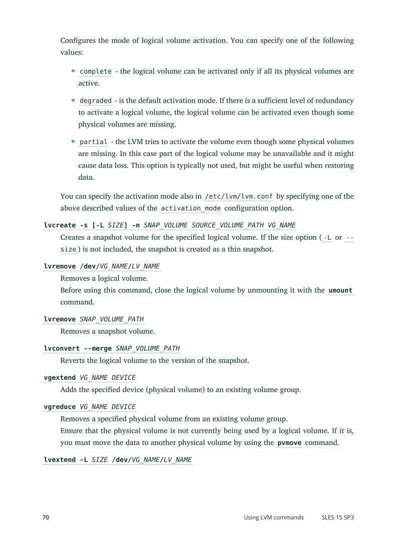
Configures the mode of logical volume activation. You can specify one of the followingvalues:
complete - the logical volume can be activated only if all its physical volumes areactive.
degraded - is the default activation mode. If there is a sufficient level of redundancyto activate a logical volume, the logical volume can be activated even though somephysical volumes are missing.
partial - the LVM tries to activate the volume even though some physical volumesare missing. In this case part of the logical volume may be unavailable and it mightcause data loss. This option is typically not used, but might be useful when restoringdata.
You can specify the activation mode also in /etc/lvm/lvm.conf by specifying one of theabove described values of the activation_mode configuration option.
lvcreate -s [-L SIZE] -n SNAP_VOLUME SOURCE_VOLUME_PATH VG_NAME
Creates a snapshot volume for the specified logical volume. If the size option ( -L or --size ) is not included, the snapshot is created as a thin snapshot.
lvremove /dev/VG_NAME/LV_NAME
Removes a logical volume.Before using this command, close the logical volume by unmounting it with the umountcommand.
lvremove SNAP_VOLUME_PATH
Removes a snapshot volume.
lvconvert --merge SNAP_VOLUME_PATH
Reverts the logical volume to the version of the snapshot.
vgextend VG_NAME DEVICE
Adds the specified device (physical volume) to an existing volume group.
vgreduce VG_NAME DEVICE
Removes a specified physical volume from an existing volume group.Ensure that the physical volume is not currently being used by a logical volume. If it is,you must move the data to another physical volume by using the pvmove command.
lvextend -L SIZE /dev/VG_NAME/LV_NAME
70 Using LVM commands SLES 15 SP3

Extends the size of a specified logical volume. Afterward, you must also expand the lesystem to take advantage of the newly available space. See Chapter 2, Resizing file systems
for details.
lvreduce -L SIZE /dev/VG_NAME/LV_NAME
Reduces the size of a specified logical volume.Ensure that you reduce the size of the le system rst before shrinking the volume, other-wise you risk losing data. See Chapter 2, Resizing file systems for details.
lvrename /dev/VG_NAME/LV_NAME /dev/VG_NAME/NEW_LV_NAME
Renames an existing LVM logical volume. It does not change the volume group name.
Tip: Bypassing udev on volume creationIn case you want to manage LV device nodes and symbolic links by using LVM insteadof by using udev rules, you can achieve this by disabling notifications from udev withone of the following methods:
Configure activation/udev_rules = 0 and activation/udev_sync = 0 in /etc/lvm/lvm.conf .Note that specifying --nodevsync with the lvcreate command has the same ef-fect as activation/udev_sync = 0 ; setting activation/udev_rules = 0 is stillrequired.
Setting the environment variable DM_DISABLE_UDEV :
export DM_DISABLE_UDEV=1
This will also disable notifications from udev. In addition, all udev related settingsfrom /etc/lvm/lvm.conf will be ignored.
5.8.1 Resizing a logical volume with commands
The lvresize , lvextend , and lvreduce commands are used to resize logical volumes. Seethe man pages for each of these commands for syntax and options information. To extend an LVthere must be enough unallocated space available on the VG.
The recommended way to grow or shrink a logical volume is to use the YaST Partitioner. Whenusing YaST, the size of the le system in the volume will automatically be adjusted, too.
71 Resizing a logical volume with commands SLES 15 SP3

LVs can be extended or shrunk manually while they are being used, but this may not be true fora le system on them. Extending or shrinking the LV does not automatically modify the size ofle systems in the volume. You must use a different command to grow the le system afterward.For information about resizing le systems, see Chapter 2, Resizing file systems.
Ensure that you use the right sequence when manually resizing an LV:
If you extend an LV, you must extend the LV before you attempt to grow the le system.
If you shrink an LV, you must shrink the le system before you attempt to shrink the LV.
To extend the size of a logical volume:
1. Open a terminal console.
2. If the logical volume contains an Ext2 or Ext4 le system, which do not support onlinegrowing, dismount it. In case it contains le systems that are hosted for a virtual machine(such as a Xen VM), shut down the VM rst.
3. At the terminal console prompt, enter the following command to grow the size of thelogical volume:
> sudo lvextend -L +SIZE /dev/VG_NAME/LV_NAME
For SIZE , specify the amount of space you want to add to the logical volume, such as 10GB. Replace /dev/VG_NAME/LV_NAME with the Linux path to the logical volume, such as/dev/LOCAL/DATA . For example:
> sudo lvextend -L +10GB /dev/vg1/v1
4. Adjust the size of the le system. See Chapter 2, Resizing file systems for details.
5. In case you have dismounted the le system, mount it again.
For example, to extend an LV with a (mounted and active) Btrfs on it by 10 GB:
> sudo lvextend −L +10G /dev/LOCAL/DATA> sudo btrfs filesystem resize +10G /dev/LOCAL/DATA
To shrink the size of a logical volume:
1. Open a terminal console.
72 Resizing a logical volume with commands SLES 15 SP3

2. If the logical volume does not contain a Btrfs le system, dismount it. In case it containsle systems that are hosted for a virtual machine (such as a Xen VM), shut down the VMrst. Note that volumes with the XFS le system cannot be reduced in size.
3. Adjust the size of the le system. See Chapter 2, Resizing file systems for details.
4. At the terminal console prompt, enter the following command to shrink the size of thelogical volume to the size of the le system:
> sudo lvreduce /dev/VG_NAME/LV_NAME
5. In case you have unmounted the le system, mount it again.
For example, to shrink an LV with a Btrfs on it by 5 GB:
> sudo btrfs filesystem resize -size 5G /dev/LOCAL/DATAsudo lvreduce /dev/LOCAL/DATA
Tip: Resizing the Volume and the File System with a SingleCommandStarting with SUSE Linux Enterprise Server 12 SP1, lvextend , lvresize , and lvreducesupport the option --resizefs which will not only change the size of the volume, butwill also resize the le system. Therefore the examples for lvextend and lvreduceshown above can alternatively be run as follows:
> sudo lvextend --resizefs −L +10G /dev/LOCAL/DATA> sudo lvreduce --resizefs -L -5G /dev/LOCAL/DATA
Note that the --resizefs is supported for the following le systems: ext2/3/4, Btrfs,XFS. Resizing Btrfs with this option is currently only available on SUSE Linux EnterpriseServer, since it is not yet accepted upstream.
5.8.2 Using LVM cache volumes
LVM supports the use of fast block devices (such as an SSD device) as write-back or write-through caches for large slower block devices. The cache logical volume type uses a small andfast LV to improve the performance of a large and slow LV.
73 Using LVM cache volumes SLES 15 SP3

To set up LVM caching, you need to create two logical volumes on the caching device. A largeone is used for the caching itself, a smaller volume is used to store the caching metadata. Thesetwo volumes need to be part of the same volume group as the original volume. When thesevolumes are created, they need to be converted into a cache pool which needs to be attachedto the original volume:
PROCEDURE 5.2: SETTING UP A CACHED LOGICAL VOLUME
1. Create the original volume (on a slow device) if not already existing.
2. Add the physical volume (from a fast device) to the same volume group the original volumeis part of and create the cache data volume on the physical volume.
3. Create the cache metadata volume. The size should be 1/1000 of the size of the cachedata volume, with a minimum size of 8 MB.
4. Combine the cache data volume and metadata volume into a cache pool volume:
> sudo lvconvert --type cache-pool --poolmetadata VOLUME_GROUP/METADATA_VOLUME VOLUME_GROUP/CACHING_VOLUME
5. Attach the cache pool to the original volume:
> sudo lvconvert --type cache --cachepool VOLUME_GROUP/CACHING_VOLUME VOLUME_GROUP/ORIGINAL_VOLUME
For more information on LVM caching, see the lvmcache(7) man page.
5.9 Tagging LVM2 storage objectsA tag is an unordered keyword or term assigned to the metadata of a storage object. Taggingallows you to classify collections of LVM storage objects in ways that you nd useful by attachingan unordered list of tags to their metadata.
74 Tagging LVM2 storage objects SLES 15 SP3

5.9.1 Using LVM2 tags
After you tag the LVM2 storage objects, you can use the tags in commands to accomplish thefollowing tasks:
Select LVM objects for processing according to the presence or absence of specific tags.
Use tags in the configuration le to control which volume groups and logical volumes areactivated on a server.
Override settings in a global configuration le by specifying tags in the command.
A tag can be used in place of any command line LVM object reference that accepts:
a list of objects
a single object as long as the tag expands to a single object
Replacing the object name with a tag is not supported everywhere yet. After the arguments areexpanded, duplicate arguments in a list are resolved by removing the duplicate arguments, andretaining the rst instance of each argument.
Wherever there might be ambiguity of argument type, you must prefix a tag with the commercialat sign (@) character, such as @mytag . Elsewhere, using the “@” prefix is optional.
5.9.2 Requirements for creating LVM2 tags
Consider the following requirements when using tags with LVM:
Supported characters
An LVM tag word can contain the ASCII uppercase characters A to Z, lowercase charactersa to z, numbers 0 to 9, underscore (_), plus (+), hyphen (-), and period (.). The wordcannot begin with a hyphen. The maximum length is 128 characters.
Supported storage objects
You can tag LVM2 physical volumes, volume groups, logical volumes, and logical volumesegments. PV tags are stored in its volume group’s metadata. Deleting a volume group alsodeletes the tags in the orphaned physical volume. Snapshots cannot be tagged, but theirorigin can be tagged.LVM1 objects cannot be tagged because the disk format does not support it.
75 Using LVM2 tags SLES 15 SP3

5.9.3 Command line tag syntax
--addtag TAG_INFO
Add a tag to (or tag) an LVM2 storage object. Example:
> sudo vgchange --addtag @db1 vg1
--deltag TAG_INFO
Remove a tag from (or untag) an LVM2 storage object. Example:
> sudo vgchange --deltag @db1 vg1
--tag TAG_INFO
Specify the tag to use to narrow the list of volume groups or logical volumes to be activatedor deactivated.Enter the following to activate the volume if it has a tag that matches the tag provided(example):
> sudo lvchange -ay --tag @db1 vg1/vol2
5.9.4 Configuration file syntax
The following sections show example configurations for certain use cases.
5.9.4.1 Enabling host name tags in the lvm.conf file
Add the following code to the /etc/lvm/lvm.conf le to enable host tags that are definedseparately on host in a /etc/lvm/lvm_<HOSTNAME>.conf le.
tags { # Enable hostname tags hosttags = 1}
You place the activation code in the /etc/lvm/lvm_<HOSTNAME>.conf le on the host. SeeSection 5.9.4.3, “Defining activation”.
5.9.4.2 Defining tags for host names in the lvm.conf file
tags {
76 Command line tag syntax SLES 15 SP3

tag1 { } # Tag does not require a match to be set.
tag2 { # If no exact match, tag is not set. host_list = [ "hostname1", "hostname2" ] }}
5.9.4.3 Defining activation
You can modify the /etc/lvm/lvm.conf le to activate LVM logical volumes based on tags.
In a text editor, add the following code to the le:
activation { volume_list = [ "vg1/lvol0", "@database" ] }
Replace @database with your tag. Use "@*" to match the tag against any tag set on the host.
The activation command matches against VGNAME , VGNAME/LVNAME , or @ TAG set in the meta-data of volume groups and logical volumes. A volume group or logical volume is activated onlyif a metadata tag matches. The default if there is no match, is not to activate.
If volume_list is not present and tags are defined on the host, then it activates the volumegroup or logical volumes only if a host tag matches a metadata tag.
If volume_list is defined, but empty, and no tags are defined on the host, then it does notactivate.
If volume_list is undefined, it imposes no limits on LV activation (all are allowed).
5.9.4.4 Defining activation in multiple host name configuration files
You can use the activation code in a host’s configuration le ( /etc/lvm/lvm_<HOST_TAG>.conf ) when host tags are enabled in the lvm.conf le. For example, a serverhas two configuration les in the /etc/lvm/ directory:
lvm.conf
lvm_<HOST_TAG>.conf
At start-up, load the /etc/lvm/lvm.conf le, and process any tag settings in the le. If any hosttags were defined, it loads the related /etc/lvm/lvm_<HOST_TAG>.conf le. When it searchesfor a specific configuration le entry, it searches the host tag le rst, then the lvm.conf le,
77 Configuration file syntax SLES 15 SP3

and stops at the rst match. Within the lvm_<HOST_TAG>.conf le, use the reverse order thattags were set in. This allows the le for the last tag set to be searched rst. New tags set in thehost tag le will trigger additional configuration le loads.
5.9.5 Using tags for a simple activation control in a cluster
You can set up a simple host name activation control by enabling the hostname_tags optionin the /etc/lvm/lvm.conf le. Use the same le on every machine in a cluster so that it isa global setting.
1. In a text editor, add the following code to the /etc/lvm/lvm.conf le:
tags { hostname_tags = 1}
2. Replicate the le to all hosts in the cluster.
3. From any machine in the cluster, add db1 to the list of machines that activate vg1/lvol2 :
> sudo lvchange --addtag @db1 vg1/lvol2
4. On the db1 server, enter the following to activate it:
> sudo lvchange -ay vg1/vol2
5.9.6 Using tags to activate on preferred hosts in a cluster
The examples in this section demonstrate two methods to accomplish the following:
Activate volume group vg1 only on the database hosts db1 and db2 .
Activate volume group vg2 only on the le server host fs1 .
Activate nothing initially on the le server backup host fsb1 , but be prepared for it totake over from the le server host fs1 .
5.9.6.1 Option 1: centralized admin and static configuration replicatedbetween hosts
In the following solution, the single configuration le is replicated among multiple hosts.
78 Using tags for a simple activation control in a cluster SLES 15 SP3

1. Add the @database tag to the metadata of volume group vg1 . In a terminal console, enter
> sudo vgchange --addtag @database vg1
2. Add the @fileserver tag to the metadata of volume group vg2 . In a terminal console,enter
> sudo vgchange --addtag @fileserver vg2
3. In a text editor, modify the /etc/lvm/lvm.conf le with the following code to definethe @database , @fileserver , @fileserverbackup tags.
tags { database { host_list = [ "db1", "db2" ] } fileserver { host_list = [ "fs1" ] } fileserverbackup { host_list = [ "fsb1" ] }}
activation { # Activate only if host has a tag that matches a metadata tag volume_list = [ "@*" ]}
4. Replicate the modified /etc/lvm/lvm.conf le to the four hosts: db1 , db2 , fs1 , andfsb1 .
5. If the le server host goes down, vg2 can be brought up on fsb1 by entering the followingcommands in a terminal console on any node:
> sudo vgchange --addtag @fileserverbackup vg2> sudo vgchange -ay vg2
5.9.6.2 Option 2: localized admin and configuration
In the following solution, each host holds locally the information about which classes of volumeto activate.
1. Add the @database tag to the metadata of volume group vg1 . In a terminal console, enter
79 Using tags to activate on preferred hosts in a cluster SLES 15 SP3

> sudo vgchange --addtag @database vg1
2. Add the @fileserver tag to the metadata of volume group vg2 . In a terminal console,enter
> sudo vgchange --addtag @fileserver vg2
3. Enable host tags in the /etc/lvm/lvm.conf le:
a. In a text editor, modify the /etc/lvm/lvm.conf le with the following code toenable host tag configuration les.
tags { hosttags = 1}
b. Replicate the modified /etc/lvm/lvm.conf le to the four hosts: db1 , db2 , fs1 ,and fsb1 .
4. On host db1 , create an activation configuration le for the database host db1 . In a texteditor, create /etc/lvm/lvm_db1.conf le and add the following code:
activation { volume_list = [ "@database" ]}
5. On host db2 , create an activation configuration le for the database host db2 . In a texteditor, create /etc/lvm/lvm_db2.conf le and add the following code:
activation { volume_list = [ "@database" ]}
6. On host fs1, create an activation configuration le for the le server host fs1 . In a texteditor, create /etc/lvm/lvm_fs1.conf le and add the following code:
activation { volume_list = [ "@fileserver" ]}
80 Using tags to activate on preferred hosts in a cluster SLES 15 SP3

7. If the le server host fs1 goes down, to bring up a spare le server host fsb1 as a leserver:
a. On host fsb1 , create an activation configuration le for the host fsb1 . In a texteditor, create /etc/lvm/lvm_fsb1.conf le and add the following code:
activation { volume_list = [ "@fileserver" ]}
b. In a terminal console, enter one of the following commands:
> sudo vgchange -ay vg2> sudo vgchange -ay @fileserver
81 Using tags to activate on preferred hosts in a cluster SLES 15 SP3

6 LVM volume snapshots
A Logical Volume Manager (LVM) logical volume snapshot is a copy-on-write technology thatmonitors changes to an existing volume’s data blocks so that when a write is made to one ofthe blocks, the block’s value at the snapshot time is copied to a snapshot volume. In this way, apoint-in-time copy of the data is preserved until the snapshot volume is deleted.
6.1 Understanding volume snapshotsA le system snapshot contains metadata about itself and data blocks from a source logicalvolume that has changed since the snapshot was taken. When you access data via the snapshot,you see a point-in-time copy of the source logical volume. There is no need to restore data frombackup media or to overwrite the changed data.
Important: Mounting volumes with snapshotsDuring the snapshot’s lifetime, the snapshot must be mounted before its source logicalvolume can be mounted.
LVM volume snapshots allow you to create a backup from a point-in-time view of the le system.The snapshot is created instantly and persists until you delete it. You can back up the le systemfrom the snapshot while the volume itself continues to be available for users. The snapshotinitially contains some metadata about the snapshot, but no actual data from the source logicalvolume. Snapshot uses copy-on-write technology to detect when data changes in an originaldata block. It copies the value it held when the snapshot was taken to a block in the snapshotvolume, then allows the new data to be stored in the source block. As more blocks change fromtheir original value on the source logical volume, the snapshot size grows.
When you are sizing the snapshot, consider how much data is expected to change on the sourcelogical volume and how long you plan to keep the snapshot. The amount of space that youallocate for a snapshot volume can vary, depending on the size of the source logical volume,how long you plan to keep the snapshot, and the number of data blocks that are expected tochange during the snapshot’s lifetime. The snapshot volume cannot be resized after it is created.As a guide, create a snapshot volume that is about 10% of the size of the original logical volume.If you anticipate that every block in the source logical volume will change at least one time
82 Understanding volume snapshots SLES 15 SP3

before you delete the snapshot, then the snapshot volume should be at least as large as thesource logical volume plus some additional space for metadata about the snapshot volume. Lessspace is required if the data changes infrequently or if the expected lifetime is sufficiently brief.
In LVM2, snapshots are read/write by default. When you write data directly to the snapshot,that block is marked in the exception table as used, and never gets copied from the sourcelogical volume. You can mount the snapshot volume, and test application changes by writingdata directly to the snapshot volume. You can easily discard the changes by dismounting thesnapshot, removing the snapshot, and then remounting the source logical volume.
In a virtual guest environment, you can use the snapshot function for LVM logical volumes youcreate on the server’s disks, as you would on a physical server.
In a virtual host environment, you can use the snapshot function to back up the virtual machine’sstorage back-end, or to test changes to a virtual machine image, such as for patches or upgrades,without modifying the source logical volume. The virtual machine must be using an LVM logicalvolume as its storage back-end, as opposed to using a virtual disk le. You can mount the LVMlogical volume and use it to store the virtual machine image as a le-backed disk, or you canassign the LVM logical volume as a physical disk to write to it as a block device.
Beginning in SLES 11 SP3, an LVM logical volume snapshot can be thinly provisioned. Thinprovisioning is assumed if you create a snapshot without a specified size. The snapshot is createdas a thin volume that uses space as needed from a thin pool. A thin snapshot volume has the samecharacteristics as any other thin volume. You can independently activate the volume, extendthe volume, rename the volume, remove the volume, and even snapshot the volume.
Important: Thinly provisioned volumes in a clusterTo use thinly provisioned snapshots in a cluster, the source logical volume and its snap-shots must be managed in a single cluster resource. This allows the volume and its snap-shots to always be mounted exclusively on the same node.
When you are done with the snapshot, it is important to remove it from the system. A snapshoteventually lls up completely as data blocks change on the source logical volume. When thesnapshot is full, it is disabled, which prevents you from remounting the source logical volume.
If you create multiple snapshots for a source logical volume, remove the snapshots in a lastcreated, rst deleted order.
83 Understanding volume snapshots SLES 15 SP3

6.2 Creating Linux snapshots with LVMThe Logical Volume Manager (LVM) can be used for creating snapshots of your le system.
Open a terminal console and enter
> sudo lvcreate -s [-L <size>] -n SNAP_VOLUME SOURCE_VOLUME_PATH
If no size is specified, the snapshot is created as a thin snapshot.
For example:
> sudo lvcreate -s -L 1G -n linux01-snap /dev/lvm/linux01
The snapshot is created as the /dev/lvm/linux01-snap volume.
6.3 Monitoring a snapshotOpen a terminal console and enter
> sudo lvdisplay SNAP_VOLUME
For example:
> sudo lvdisplay /dev/vg01/linux01-snap
--- Logical volume --- LV Name /dev/lvm/linux01 VG Name vg01 LV UUID QHVJYh-PR3s-A4SG-s4Aa-MyWN-Ra7a-HL47KL LV Write Access read/write LV snapshot status active destination for /dev/lvm/linux01 LV Status available # open 0 LV Size 80.00 GB Current LE 1024 COW-table size 8.00 GB COW-table LE 512 Allocated to snapshot 30% Snapshot chunk size 8.00 KB Segments 1 Allocation inherit Read ahead sectors 0 Block device 254:5
84 Creating Linux snapshots with LVM SLES 15 SP3

6.4 Deleting Linux snapshotsOpen a terminal console and enter
> sudo lvremove SNAP_VOLUME_PATH
For example:
> sudo lvremove /dev/lvmvg/linux01-snap
6.5 Using snapshots for virtual machines on a virtualhostUsing an LVM logical volume for a virtual machine’s back-end storage allows flexibility in ad-ministering the underlying device, such as making it easier to move storage objects, create snap-shots, and back up data. You can mount the LVM logical volume and use it to store the virtualmachine image as a le-backed disk, or you can assign the LVM logical volume as a physicaldisk to write to it as a block device. You can create a virtual disk image on the LVM logicalvolume, then snapshot the LVM.
You can leverage the read/write capability of the snapshot to create different instances of avirtual machine, where the changes are made to the snapshot for a particular virtual machineinstance. You can create a virtual disk image on an LVM logical volume, snapshot the sourcelogical volume, and modify the snapshot for a particular virtual machine instance. You can createanother snapshot of the source logical volume, and modify it for a different virtual machineinstance. The majority of the data for the different virtual machine instances resides with theimage on the source logical volume.
You can also leverage the read/write capability of the snapshot to preserve the virtual diskimage while testing patches or upgrades in the guest environment. You create a snapshot of theLVM volume that contains the image, and then run the virtual machine on the snapshot location.The source logical volume is unchanged, and all changes for that machine are written to thesnapshot. To return to the source logical volume of the virtual machine image, you power o thevirtual machine, then remove the snapshot from the source logical volume. To start over, you re-create the snapshot, mount the snapshot, and restart the virtual machine on the snapshot image.
85 Deleting Linux snapshots SLES 15 SP3

The following procedure uses a le-backed virtual disk image and the Xen hypervisor. You canadapt the procedure in this section for other hypervisors that run on the SUSE Linux Enterpriseplatform, such as KVM. To run a le-backed virtual machine image from the snapshot volume:
1. Ensure that the source logical volume that contains the le-backed virtual machine imageis mounted, such as at mount point /var/lib/xen/images/<IMAGE_NAME> .
2. Create a snapshot of the LVM logical volume with enough space to store the differencesthat you expect.
> sudo lvcreate -s -L 20G -n myvm-snap /dev/lvmvg/myvm
If no size is specified, the snapshot is created as a thin snapshot.
3. Create a mount point where you will mount the snapshot volume.
> sudo mkdir -p /mnt/xen/vm/myvm-snap
4. Mount the snapshot volume at the mount point you created.
> sudo mount -t auto /dev/lvmvg/myvm-snap /mnt/xen/vm/myvm-snap
5. In a text editor, copy the configuration le for the source virtual machine, modify thepaths to point to the le-backed image le on the mounted snapshot volume, and savethe le such as /etc/xen/myvm-snap.cfg .
6. Start the virtual machine using the mounted snapshot volume of the virtual machine.
> sudo xm create -c /etc/xen/myvm-snap.cfg
7. (Optional) Remove the snapshot, and use the unchanged virtual machine image on thesource logical volume.
> sudo umount /mnt/xenvms/myvm-snap> sudo lvremove -f /dev/lvmvg/mylvm-snap
8. (Optional) Repeat this process as desired.
86 Using snapshots for virtual machines on a virtual host SLES 15 SP3

6.6 Merging a snapshot with the source logicalvolume to revert changes or roll back to a previousstateSnapshots can be useful if you need to roll back or restore data on a volume to a previous state.For example, you might need to revert data changes that resulted from an administrator erroror a failed or undesirable package installation or upgrade.
You can use the lvconvert --merge command to revert the changes made to an LVM logicalvolume. The merging begins as follows:
If both the source logical volume and snapshot volume are not open, the merge beginsimmediately.
If the source logical volume or snapshot volume are open, the merge starts the rst timeeither the source logical volume or snapshot volume are activated and both are closed.
If the source logical volume cannot be closed, such as the root le system, the merge isdeferred until the next time the server reboots and the source logical volume is activated.
If the source logical volume contains a virtual machine image, you must shut down thevirtual machine, deactivate the source logical volume and snapshot volume (by dismount-ing them in that order), and then issue the merge command. Because the source logicalvolume is automatically remounted and the snapshot volume is deleted when the mergeis complete, you should not restart the virtual machine until after the merge is complete.After the merge is complete, you use the resulting logical volume for the virtual machine.
After a merge begins, the merge continues automatically after server restarts until it is complete.A new snapshot cannot be created for the source logical volume while a merge is in progress.
While the merge is in progress, reads or writes to the source logical volume are transparentlyredirected to the snapshot that is being merged. This allows users to immediately view andaccess the data as it was when the snapshot was created. They do not need to wait for the mergeto complete.
When the merge is complete, the source logical volume contains the same data as it did whenthe snapshot was taken, plus any data changes made after the merge began. The resulting logicalvolume has the source logical volume’s name, minor number, and UUID. The source logicalvolume is automatically remounted, and the snapshot volume is removed.
1. Open a terminal console and enter
87
Merging a snapshot with the source logical volume to revert changes or roll back to a previous
state SLES 15 SP3

> sudo lvconvert --merge [-b] [-i SECONDS] [SNAP_VOLUME_PATH[...snapN]|@VOLUME_TAG]
You can specify one or multiple snapshots on the command line. You can alternatively tagmultiple source logical volumes with the same volume tag then specify @<VOLUME_TAG>on the command line. The snapshots for the tagged volumes are merged to their respectivesource logical volumes. For information about tagging logical volumes, see Section 5.9,
“Tagging LVM2 storage objects”.The options include:
-b,
--background
Run the daemon in the background. This allows multiple specified snapshots to bemerged concurrently in parallel.
-i,
--interval < SECONDS >
Report progress as a percentage at regular intervals. Specify the interval in seconds.
For more information about this command, see the lvconvert(8) man page.For example:
> sudo lvconvert --merge /dev/lvmvg/linux01-snap
This command merges /dev/lvmvg/linux01-snap into its source logical volume.
> sudo lvconvert --merge @mytag
If lvol1 , lvol2 , and lvol3 are all tagged with mytag , each snapshot volume is mergedserially with its respective source logical volume; that is: lvol1 , then lvol2 , then lvol3 .If the --background option is specified, the snapshots for the respective tagged logicalvolume are merged concurrently in parallel.
2. (Optional) If both the source logical volume and snapshot volume are open and they canbe closed, you can manually deactivate and activate the source logical volume to get themerge to start immediately.
> sudo umount ORIGINAL_VOLUME> sudo lvchange -an ORIGINAL_VOLUME> sudo lvchange -ay ORIGINAL_VOLUME> sudo mount ORIGINAL_VOLUME MOUNT_POINT
88
Merging a snapshot with the source logical volume to revert changes or roll back to a previous
state SLES 15 SP3

For example:
> sudo umount /dev/lvmvg/lvol01> sudo lvchange -an /dev/lvmvg/lvol01> sudo lvchange -ay /dev/lvmvg/lvol01> sudo mount /dev/lvmvg/lvol01 /mnt/lvol01
3. (Optional) If both the source logical volume and snapshot volume are open and the sourcelogical volume cannot be closed, such as the root le system, you can restart the serverand mount the source logical volume to get the merge to start immediately after the restart.
89
Merging a snapshot with the source logical volume to revert changes or roll back to a previous
state SLES 15 SP3
III Software RAID
7 Software RAID configuration 91
8 Configuring software RAID for the root partition 98
9 Creating software RAID 10 devices 106
10 Creating a degraded RAID array 121
11 Resizing software RAID arrays with mdadm 123
12 Storage enclosure LED utilities for MD software RAIDs 132
13 Troubleshooting software RAIDs 140

7 Software RAID configuration
The purpose of RAID (redundant array of independent disks) is to combine several hard diskpartitions into one large virtual hard disk to optimize performance, data security, or both. MostRAID controllers use the SCSI protocol, because it can address a larger number of hard disksin a more effective way than the IDE protocol and is more suitable for parallel processing ofcommands. There are some RAID controllers that support IDE or SATA hard disks. SoftwareRAID provides the advantages of RAID systems without the additional cost of hardware RAIDcontrollers. However, this requires some CPU time and has memory requirements that make itunsuitable for real high performance computers.
Important: RAID on cluster file systemsSoftware RAID underneath clustered le systems needs to be set up using a clustermulti-device (Cluster MD). Refer to the Administration Guide for the SUSE Linux Enter-
prise High Availability Extension (https://documentation.suse.com/sle-ha/15-SP2/html/SLE-HA-
all/cha-ha-cluster-md.html) .
SUSE Linux Enterprise offers the option of combining several hard disks into one soft RAIDsystem. RAID implies several strategies for combining several hard disks in a RAID system, eachwith different goals, advantages, and characteristics. These variations are commonly known asRAID levels.
7.1 Understanding RAID levelsThis section describes common RAID levels 0, 1, 2, 3, 4, 5, and nested RAID levels.
7.1.1 RAID 0
This level improves the performance of your data access by spreading out blocks of each leacross multiple disks. Actually, this is not a RAID, because it does not provide data backup, butthe name RAID 0 for this type of system has become the norm. With RAID 0, two or more harddisks are pooled together. The performance is very good, but the RAID system is destroyed andyour data lost if even one hard disk fails.
91 Understanding RAID levels SLES 15 SP3

7.1.2 RAID 1
This level provides adequate security for your data, because the data is copied to another harddisk 1:1. This is known as hard disk mirroring. If a disk is destroyed, a copy of its contents isavailable on another mirrored disk. All disks except one could be damaged without endangeringyour data. However, if damage is not detected, damaged data might be mirrored to the correctdisk and the data is corrupted that way. The writing performance suffers a little in the copyingprocess compared to when using single disk access (10 to 20 percent slower), but read accessis significantly faster in comparison to any one of the normal physical hard disks, because thedata is duplicated so can be scanned in parallel. RAID 1 generally provides nearly twice the readtransaction rate of single disks and almost the same write transaction rate as single disks.
7.1.3 RAID 2 and RAID 3
These are not typical RAID implementations. Level 2 stripes data at the bit level rather than theblock level. Level 3 provides byte-level striping with a dedicated parity disk and cannot servicesimultaneous multiple requests. Both levels are rarely used.
7.1.4 RAID 4
Level 4 provides block-level striping like Level 0 combined with a dedicated parity disk. If adata disk fails, the parity data is used to create a replacement disk. However, the parity diskmight create a bottleneck for write access. Nevertheless, Level 4 is sometimes used.
7.1.5 RAID 5
RAID 5 is an optimized compromise between Level 0 and Level 1 in terms of performanceand redundancy. The hard disk space equals the number of disks used minus one. The data isdistributed over the hard disks as with RAID 0. Parity blocks, created on one of the partitions,are there for security reasons. They are linked to each other with XOR, enabling the contentsto be reconstructed by the corresponding parity block in case of system failure. With RAID 5,no more than one hard disk can fail at the same time. If one hard disk fails, it must be replacedwhen possible to avoid the risk of losing data.
92 RAID 1 SLES 15 SP3

7.1.6 RAID 6
RAID 6 is an extension of RAID 5 that allows for additional fault tolerance by using a secondindependent distributed parity scheme (dual parity). Even if two of the hard disks fail duringthe data recovery process, the system continues to be operational, with no data loss.
RAID 6 provides for extremely high data fault tolerance by sustaining multiple simultaneousdrive failures. It handles the loss of any two devices without data loss. Accordingly, it requiresN+2 drives to store N drives worth of data. It requires a minimum of four devices.
The performance for RAID 6 is slightly lower but comparable to RAID 5 in normal mode andsingle disk failure mode. It is very slow in dual disk failure mode. A RAID 6 configuration needsa considerable amount of CPU time and memory for write operations.
TABLE 7.1: COMPARISON OF RAID 5 AND RAID 6
Feature RAID 5 RAID 6
Number of devices N+1, minimum of 3 N+2, minimum of 4
Parity Distributed, single Distributed, dual
Performance Medium impact on write andrebuild
More impact on sequentialwrite than RAID 5
Fault-tolerance Failure of one componentdevice
Failure of two componentdevices
7.1.7 Nested and complex RAID levels
Other RAID levels have been developed, such as RAIDn, RAID 10, RAID 0+1, RAID 30, andRAID 50. Some are proprietary implementations created by hardware vendors. Examples forcreating RAID 10 configurations can be found in Chapter 9, Creating software RAID 10 devices.
7.2 Soft RAID configuration with YaSTThe YaST soft RAID configuration can be reached from the YaST Expert Partitioner. This par-titioning tool also enables you to edit and delete existing partitions and create new ones thatshould be used with soft RAID. These instructions apply on setting up RAID levels 0, 1, 5, and6. Setting up RAID 10 configurations is explained in Chapter 9, Creating software RAID 10 devices.
93 RAID 6 SLES 15 SP3

1. Launch YaST and open the Partitioner.
2. If necessary, create partitions that should be used with your RAID configuration. Do notformat them and set the partition type to 0xFD Linux RAID. When using existing partitionsit is not necessary to change their partition type—YaST will automatically do so. Referto Book “Deployment Guide”, Chapter 10 “Expert Partitioner”, Section 10.1 “Using the Expert Par-
titioner” for details.It is strongly recommended to use partitions stored on different hard disks to decreasethe risk of losing data if one is defective (RAID 1 and 5) and to optimize the performanceof RAID 0.For RAID 0 at least two partitions are needed. RAID 1 requires exactly two partitions,while at least three partitions are required for RAID 5. A RAID 6 setup requires at leastfour partitions. It is recommended to use only partitions of the same size because eachsegment can contribute only the same amount of space as the smallest sized partition.
3. In the left panel, select RAID.A list of existing RAID configurations opens in the right panel.
4. At the lower left of the RAID page, click Add RAID.
5. Select a RAID Type and Add an appropriate number of partitions from the Available Devicesdialog.You can optionally assign a RAID Name to your RAID. It will make it available as /dev/md/NAME . See Section 7.2.1, “RAID names” for more information.
94 Soft RAID configuration with YaST SLES 15 SP3

FIGURE 7.1: EXAMPLE RAID 5 CONFIGURATION
Proceed with Next.
6. Select the Chunk Size and, if applicable, the Parity Algorithm. The optimal chunk sizedepends on the type of data and the type of RAID. See https://raid.wiki.kernel.org/in-
dex.php/RAID_setup#Chunk_sizes for more information. More information on parity al-gorithms can be found with man 8 mdadm when searching for the --layout option. Ifunsure, stick with the defaults.
7. Choose a Role for the volume. Your choice here only affects the default values for theupcoming dialog. They can be changed in the next step. If in doubt, choose Raw Volume(Unformatted).
8. Under Formatting Options, select Format Partition, then select the File system. The contentof the Options menu depends on the le system. Usually there is no need to change thedefaults.Under Mounting Options, select Mount partition, then select the mount point. Click FstabOptions to add special mounting options for the volume.
9. Click Finish.
10. Click Next, verify that the changes are listed, then click Finish.
95 Soft RAID configuration with YaST SLES 15 SP3

Important: RAID on disksWhile the partitioner makes it possible to create a RAID on top of disks instead of par-titions, we do not recommend this approach for a number of reasons. Installing a boot-loader on such RAID is not supported, so you need to use a separate device for booting.Tools like fdisk and parted do not work properly with such RAIDs, which may lead toincorrect diagnosis and actions by a person who is unaware of the RAID's particular setup.
7.2.1 RAID names
By default, software RAID devices have numeric names following the pattern mdN , where N isa number. As such they can be accessed as, for example, /dev/md127 and are listed as md127in /proc/mdstat and /proc/partitions . Working with these names can be clumsy. SUSELinux Enterprise Server offers two ways to work around this problem:
Providing a named link to the device
You can optionally specify a name for the RAID device when creating it with YaST or onthe command line with mdadm --create '/dev/md/ NAME '. The device name will stillbe mdN , but a link /dev/md/NAME will be created:
> ls -og /dev/mdtotal 0lrwxrwxrwx 1 8 Dec 9 15:11 myRAID -> ../md127
The device will still be listed as md127 under /proc .
Providing a named device
In case a named link to the device is not sufficient for your setup, add the line CREATEnames=yes to /etc/mdadm.conf by running the following command:
> sudo echo "CREATE names=yes" >> /etc/mdadm.conf
This will cause names like myRAID to be used as a “real” device name. The device will notonly be accessible at /dev/myRAID , but also be listed as myRAID under /proc . Note thatthis will only apply to RAIDs configured after the change to the configuration le. ActiveRAIDs will continue to use the mdN names until they get stopped and re-assembled.
96 RAID names SLES 15 SP3

Warning: Incompatible toolsNot all tools may support named RAID devices. In case a tool expects a RAID deviceto be named mdN , it will fail to identify the devices.
7.3 Monitoring software RAIDsYou can run mdadm as a daemon in the monitor mode to monitor your software RAID. Inthe monitor mode, mdadm performs regular checks on the array for disk failures. If there is afailure, mdadm sends an email to the administrator. To define the time interval of the checks,run the following command:
mdadm --monitor --mail=root@localhost --delay=1800 /dev/md2
The command above turns on monitoring of the /dev/md2 array in intervals of 1800 seconds.In the event of a failure, an email will be sent to root@localhost .
Note: RAID checks are enabled by defaultThe RAID checks are enabled by default. It may happen that the interval between eachcheck is not long enough and you may encounter warnings. Thus, you can increase theinterval by setting a higher value with the delay option.
7.4 More informationConfiguration instructions and more details for soft RAID can be found in the HOWTOs at:
The Linux RAID wiki: https://raid.wiki.kernel.org/
The Software RAID HOWTO in the /usr/share/doc/packages/mdadm/Soft-
ware-RAID.HOWTO.html le
Linux RAID mailing lists are also available, such as linux-raid at http://marc.info/?l=linux-raid .
97 Monitoring software RAIDs SLES 15 SP3
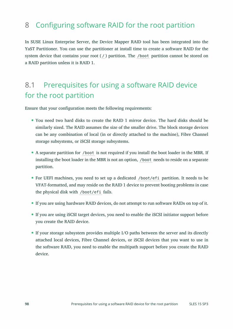
8 Configuring software RAID for the root partition
In SUSE Linux Enterprise Server, the Device Mapper RAID tool has been integrated into theYaST Partitioner. You can use the partitioner at install time to create a software RAID for thesystem device that contains your root ( / ) partition. The /boot partition cannot be stored ona RAID partition unless it is RAID 1.
8.1 Prerequisites for using a software RAID devicefor the root partitionEnsure that your configuration meets the following requirements:
You need two hard disks to create the RAID 1 mirror device. The hard disks should besimilarly sized. The RAID assumes the size of the smaller drive. The block storage devicescan be any combination of local (in or directly attached to the machine), Fibre Channelstorage subsystems, or iSCSI storage subsystems.
A separate partition for /boot is not required if you install the boot loader in the MBR. Ifinstalling the boot loader in the MBR is not an option, /boot needs to reside on a separatepartition.
For UEFI machines, you need to set up a dedicated /boot/efi partition. It needs to beVFAT-formatted, and may reside on the RAID 1 device to prevent booting problems in casethe physical disk with /boot/efi fails.
If you are using hardware RAID devices, do not attempt to run software RAIDs on top of it.
If you are using iSCSI target devices, you need to enable the iSCSI initiator support beforeyou create the RAID device.
If your storage subsystem provides multiple I/O paths between the server and its directlyattached local devices, Fibre Channel devices, or iSCSI devices that you want to use inthe software RAID, you need to enable the multipath support before you create the RAIDdevice.
98 Prerequisites for using a software RAID device for the root partition SLES 15 SP3

8.2 Setting up the system with a software RAIDdevice for the root (/) partition
1. Start the installation with YaST and proceed as described in Book “Deployment Guide”,
Chapter 8 “Installation steps” until you reach the Suggested Partitioning step.
2. Click Expert Partitioner to open the custom partitioning tool. You can use the suggestedproposal or you can use the existing proposal.
3. (Optional) If there are iSCSI target devices that you want to use, you need to enable theiSCSI Initiator software by choosing System Configure Configure iSCSI from the upperleft section of the screen. Refer to Chapter 15, Mass storage over IP networks: iSCSI for furtherdetails.
4. (Optional) If there are FCoE target devices that you want to use, you need to configurethe interface by clicking System Configure Configure FCoE from the upper left section ofthe screen.
5. (Optional) In case you need to discard the partitioning changes, click System Rescan De-vices.
6. Set up the Linux RAID format for each of the devices you want to use for the softwareRAID. You should use RAID for / , /boot/efi , or swap partitions.
a. In the left panel, select Hard Disks and select the device you want to use, then clickAdd Partition.
b. Under New Partition Size, specify the size to use, then click Next.
c. Under Role, choose Raw Volume (unformatted).
d. Select Do not format and Do not mount and set the Partition ID to Linux RAID.
e. Click Next and repeat these instructions for the second partition.
99 Setting up the system with a software RAID device for the root (/) partition SLES 15 SP3

7. Create the RAID device for the / partition.
a. In the left panel, select RAID and then Add RAID.
b. Set the desired RAID Type for the / partition and the RAID name to system .
c. Select the two RAID devices you prepared in the previous step from the AvailableDevices section and Add them.
100 Setting up the system with a software RAID device for the root (/) partition SLES 15 SP3

Proceed with Next.
d. Select the chunk size from the drop-down box. Sticking with the default is a safechoice.
e. In the left panel, click the RAID. In the Device Overview tab, select your new RAIDand click Edit.
101 Setting up the system with a software RAID device for the root (/) partition SLES 15 SP3

f. Under Role, select Operating System and proceed with Next.
g. Select the File System and set the mount point to / . Leave the dialog with Next .
8. The software RAID device is managed by Device Mapper, and creates a device under the/dev/md/system path.
102 Setting up the system with a software RAID device for the root (/) partition SLES 15 SP3

9. Optionally, you can create a swap partition in RAID. Use similar steps to those describedabove, but under the Role, select swap. Select the le system and mount point as shownbelow. Click Next.
10. Optionally, for UEFI machines, use similar steps to create the /boot/efi mounted parti-tion. Remember that only RAID 1 is supported for /boot/efi , and the partition needs tobe formatted with the FAT32 le system.
103 Setting up the system with a software RAID device for the root (/) partition SLES 15 SP3

The partitioning then looks as follows:
11. Click Accept to leave the partitioner.The new proposal appears on the Suggested Partitioning page.
104 Setting up the system with a software RAID device for the root (/) partition SLES 15 SP3

12. Continue with the installation. For UEFI machines with a separate /boot/efi partition,click Booting on the Installation Settings screen and set GRUB2 for EFI as the Boot Loader.Check that the Enable Secure Boot Support option is activated.Whenever you reboot your server, Device Mapper is started at boot time so that the soft-ware RAID is automatically recognized, and the operating system on the root ( / ) partitioncan be started.
105 Setting up the system with a software RAID device for the root (/) partition SLES 15 SP3

9 Creating software RAID 10 devices
This section describes how to set up nested and complex RAID 10 devices. A RAID 10 deviceconsists of nested RAID 1 (mirroring) and RAID 0 (striping) arrays. Nested RAIDs can either beset up as striped mirrors (RAID 1+0) or as mirrored stripes (RAID 0+1). A complex RAID 10setup also combines mirrors and stripes and additional data security by supporting a higher dataredundancy level.
9.1 Creating nested RAID 10 devices with mdadmA nested RAID device consists of a RAID array that uses another RAID array as its basic element,instead of using physical disks. The goal of this configuration is to improve the performance andfault tolerance of the RAID. Setting up nested RAID levels is not supported by YaST, but can bedone by using the mdadm command line tool.
Based on the order of nesting, two different nested RAIDs can be set up. This document usesthe following terminology:
RAID 1+0: RAID 1 (mirror) arrays are built rst, then combined to form a RAID 0 (stripe)array.
RAID 0+1: RAID 0 (stripe) arrays are built rst, then combined to form a RAID 1 (mirror)array.
The following table describes the advantages and disadvantages of RAID 10 nesting as 1+0versus 0+1. It assumes that the storage objects you use reside on different disks, each with adedicated I/O capability.
TABLE 9.1: NESTED RAID LEVELS
RAID Level Description Performance and Fault Tolerance
10 (1+0) RAID 0 (stripe) builtwith RAID 1 (mirror)arrays
RAID 1+0 provides high levels of I/O perfor-mance, data redundancy, and disk fault toler-ance. Because each member device in the RAID0 is mirrored individually, multiple disk failurescan be tolerated and data remains available aslong as the disks that fail are in different mirrors.
106 Creating nested RAID 10 devices with mdadm SLES 15 SP3

RAID Level Description Performance and Fault Tolerance
You can optionally configure a spare for each un-derlying mirrored array, or configure a spare toserve a spare group that serves all mirrors.
10 (0+1) RAID 1 (mirror) builtwith RAID 0 (stripe) ar-rays
RAID 0+1 provides high levels of I/O perfor-mance and data redundancy, but slightly lessfault tolerance than a 1+0. If multiple disks failon one side of the mirror, then the other mirroris available. However, if disks are lost concur-rently on both sides of the mirror, all data is lost.
This solution offers less disk fault tolerance thana 1+0 solution, but if you need to perform main-tenance or maintain the mirror on a differentsite, you can take an entire side of the mirror of-fline and still have a fully functional storage de-vice. Also, if you lose the connection between thetwo sites, either site operates independently ofthe other. That is not true if you stripe the mir-rored segments, because the mirrors are managedat a lower level.
If a device fails, the mirror on that side fails be-cause RAID 1 is not fault-tolerant. Create a newRAID 0 to replace the failed side, then resynchro-nize the mirrors.
9.1.1 Creating nested RAID 10 (1+0) with mdadm
A nested RAID 1+0 is built by creating two or more RAID 1 (mirror) devices, then using themas component devices in a RAID 0.
107 Creating nested RAID 10 (1+0) with mdadm SLES 15 SP3

Important: MultipathingIf you need to manage multiple connections to the devices, you must configure multipathI/O before configuring the RAID devices. For information, see Chapter 18, Managing mul-
tipath I/O for devices.
The procedure in this section uses the device names shown in the following table. Ensure thatyou modify the device names with the names of your own devices.
TABLE 9.2: SCENARIO FOR CREATING A RAID 10 (1+0) BY NESTING
Raw Devices RAID 1 (mirror) RAID 1+0 (striped mir-rors)
/dev/sdb1
/dev/sdc1/dev/md0
/dev/sdd1
/dev/sde1/dev/md1
/dev/md2
1. Open a terminal console.
2. If necessary, create four 0xFD Linux RAID partitions of equal size using a disk partitionersuch as parted.
3. Create two software RAID 1 devices, using two different devices for each device. At thecommand prompt, enter these two commands:
> sudo mdadm --create /dev/md0 --run --level=1 --raid-devices=2 /dev/sdb1 /dev/sdc1sudo mdadm --create /dev/md1 --run --level=1 --raid-devices=2 /dev/sdd1 /dev/sde1
4. Create the nested RAID 1+0 device. At the command prompt, enter the following com-mand using the software RAID 1 devices you created in the previous step:
> sudo mdadm --create /dev/md2 --run --level=0 --chunk=64 \--raid-devices=2 /dev/md0 /dev/md1
The default chunk size is 64 KB.
5. Create a le system on the RAID 1+0 device /dev/md2 , for example an XFS le system:
> sudo mkfs.xfs /dev/md2
108 Creating nested RAID 10 (1+0) with mdadm SLES 15 SP3

Modify the command to use a different le system.
6. Edit the /etc/mdadm.conf le or create it, if it does not exist (for example by runningsudo vi /etc/mdadm.conf ). Add the following lines (if the le already exists, the rstline probably already exists).
DEVICE containers partitionsARRAY /dev/md0 UUID=UUIDARRAY /dev/md1 UUID=UUIDARRAY /dev/md2 UUID=UUID
The UUID of each device can be retrieved with the following command:
> sudo mdadm -D /dev/DEVICE | grep UUID
7. Edit the /etc/fstab le to add an entry for the RAID 1+0 device /dev/md2 . The fol-lowing example shows an entry for a RAID device with the XFS le system and /dataas a mount point.
/dev/md2 /data xfs defaults 1 2
8. Mount the RAID device:
> sudo mount /data
9.1.2 Creating nested RAID 10 (0+1) with mdadm
A nested RAID 0+1 is built by creating two to four RAID 0 (striping) devices, then mirroringthem as component devices in a RAID 1.
Important: MultipathingIf you need to manage multiple connections to the devices, you must configure multipathI/O before configuring the RAID devices. For information, see Chapter 18, Managing mul-
tipath I/O for devices.
In this configuration, spare devices cannot be specified for the underlying RAID 0 devices be-cause RAID 0 cannot tolerate a device loss. If a device fails on one side of the mirror, you mustcreate a replacement RAID 0 device, than add it into the mirror.
109 Creating nested RAID 10 (0+1) with mdadm SLES 15 SP3

The procedure in this section uses the device names shown in the following table. Ensure thatyou modify the device names with the names of your own devices.
TABLE 9.3: SCENARIO FOR CREATING A RAID 10 (0+1) BY NESTING
Raw Devices RAID 0 (stripe) RAID 0+1 (mirroredstripes)
/dev/sdb1
/dev/sdc1/dev/md0
/dev/sdd1
/dev/sde1/dev/md1
/dev/md2
1. Open a terminal console.
2. If necessary, create four 0xFD Linux RAID partitions of equal size using a disk partitionersuch as parted.
3. Create two software RAID 0 devices, using two different devices for each RAID 0 device.At the command prompt, enter these two commands:
> sudo mdadm --create /dev/md0 --run --level=0 --chunk=64 \--raid-devices=2 /dev/sdb1 /dev/sdc1sudo mdadm --create /dev/md1 --run --level=0 --chunk=64 \--raid-devices=2 /dev/sdd1 /dev/sde1
The default chunk size is 64 KB.
4. Create the nested RAID 0+1 device. At the command prompt, enter the following com-mand using the software RAID 0 devices you created in the previous step:
> sudo mdadm --create /dev/md2 --run --level=1 --raid-devices=2 /dev/md0 /dev/md1
5. Create a le system on the RAID 1+0 device /dev/md2 , for example an XFS le system:
> sudo mkfs.xfs /dev/md2
Modify the command to use a different le system.
6. Edit the /etc/mdadm.conf le or create it, if it does not exist (for example by runningsudo vi /etc/mdadm.conf ). Add the following lines (if the le exists, the rst lineprobably already exists, too).
DEVICE containers partitions
110 Creating nested RAID 10 (0+1) with mdadm SLES 15 SP3

ARRAY /dev/md0 UUID=UUIDARRAY /dev/md1 UUID=UUIDARRAY /dev/md2 UUID=UUID
The UUID of each device can be retrieved with the following command:
> sudo mdadm -D /dev/DEVICE | grep UUID
7. Edit the /etc/fstab le to add an entry for the RAID 1+0 device /dev/md2 . The fol-lowing example shows an entry for a RAID device with the XFS le system and /dataas a mount point.
/dev/md2 /data xfs defaults 1 2
8. Mount the RAID device:
> sudo mount /data
9.2 Creating a complex RAID 10YaST (and mdadm with the --level=10 option) creates a single complex software RAID 10that combines features of both RAID 0 (striping) and RAID 1 (mirroring). Multiple copies of alldata blocks are arranged on multiple drives following a striping discipline. Component devicesshould be the same size.
The complex RAID 10 is similar in purpose to a nested RAID 10 (1+0), but differs in the fol-lowing ways:
TABLE 9.4: COMPLEX RAID 10 COMPARED TO NESTED RAID 10
Feature Complex RAID 10 Nested RAID 10 (1+0)
Number of devices Allows an even or odd num-ber of component devices
Requires an even number ofcomponent devices
Component devices Managed as a single RAIDdevice
Manage as a nested RAID de-vice
Striping Striping occurs in the nearor far layout on componentdevices.
Striping occurs consecutivelyacross component devices
111 Creating a complex RAID 10 SLES 15 SP3

Feature Complex RAID 10 Nested RAID 10 (1+0)
The far layout provides se-quential read throughputthat scales by number of dri-ves, rather than number ofRAID 1 pairs.
Multiple copies of data Two or more copies, up tothe number of devices in thearray
Copies on each mirrored seg-ment
Hot spare devices A single spare can service allcomponent devices
Configure a spare for eachunderlying mirrored array,or configure a spare to servea spare group that serves allmirrors.
9.2.1 Number of devices and replicas in the complex RAID 10
When configuring a complex RAID 10 array, you must specify the number of replicas of eachdata block that are required. The default number of replicas is two, but the value can be twoto the number of devices in the array.
You must use at least as many component devices as the number of replicas you specify. How-ever, the number of component devices in a RAID 10 array does not need to be a multiple ofthe number of replicas of each data block. The effective storage size is the number of devicesdivided by the number of replicas.
For example, if you specify two replicas for an array created with ve component devices, acopy of each block is stored on two different devices. The effective storage size for one copy ofall data is 5/2 or 2.5 times the size of a component device.
112 Number of devices and replicas in the complex RAID 10 SLES 15 SP3

9.2.2 Layout
The complex RAID 10 setup supports three different layouts which define how the data blocksare arranged on the disks. The available layouts are near (default), far and offset. They havedifferent performance characteristics, so it is important to choose the right layout for your work-load.
9.2.2.1 Near layout
With the near layout, copies of a block of data are striped near each other on different componentdevices. That is, multiple copies of one data block are at similar offsets in different devices. Nearis the default layout for RAID 10. For example, if you use an odd number of component devicesand two copies of data, some copies are perhaps one chunk further into the device.
The near layout for the complex RAID 10 yields read and write performance similar to RAID 0over half the number of drives.
Near layout with an even number of disks and two replicas:
sda1 sdb1 sdc1 sde1 0 0 1 1 2 2 3 3 4 4 5 5 6 6 7 7 8 8 9 9
Near layout with an odd number of disks and two replicas:
sda1 sdb1 sdc1 sde1 sdf1 0 0 1 1 2 2 3 3 4 4 5 5 6 6 7 7 8 8 9 9 10 10 11 11 12
9.2.2.2 Far layout
The far layout stripes data over the early part of all drives, then stripes a second copy of the dataover the later part of all drives, making sure that all copies of a block are on different drives.The second set of values starts halfway through the component drives.
113 Layout SLES 15 SP3

With a far layout, the read performance of the complex RAID 10 is similar to a RAID 0 overthe full number of drives, but write performance is substantially slower than a RAID 0 becausethere is more seeking of the drive heads. It is best used for read-intensive operations such asfor read-only le servers.
The speed of the RAID 10 for writing is similar to other mirrored RAID types, like RAID 1 andRAID 10 using near layout, as the elevator of the le system schedules the writes in a moreoptimal way than raw writing. Using RAID 10 in the far layout is well suited for mirrored writingapplications.
Far layout with an even number of disks and two replicas:
sda1 sdb1 sdc1 sde1 0 1 2 3 4 5 6 7 . . . 3 0 1 2 7 4 5 6
Far layout with an odd number of disks and two replicas:
sda1 sdb1 sdc1 sde1 sdf1 0 1 2 3 4 5 6 7 8 9 . . . 4 0 1 2 3 9 5 6 7 8
9.2.2.3 Oset layout
The offset layout duplicates stripes so that the multiple copies of a given chunk are laid outon consecutive drives and at consecutive offsets. Effectively, each stripe is duplicated and thecopies are offset by one device. This should give similar read characteristics to a far layout if asuitably large chunk size is used, but without as much seeking for writes.
Offset layout with an even number of disks and two replicas:
sda1 sdb1 sdc1 sde1 0 1 2 3 3 0 1 2 4 5 6 7 7 4 5 6 8 9 10 11
114 Layout SLES 15 SP3

11 8 9 10
Offset layout with an odd number of disks and two replicas:
sda1 sdb1 sdc1 sde1 sdf1 0 1 2 3 4 4 0 1 2 3 5 6 7 8 9 9 5 6 7 8 10 11 12 13 14 14 10 11 12 13
9.2.2.4 Specifying the number of replicas and the layout with YaST andmdadm
The number of replicas and the layout is specified as Parity Algorithm in YaST or with the --layout parameter for mdadm. The following values are accepted:
nN
Specify n for near layout and replace N with the number of replicas. n2 is the defaultthat is used when not configuring layout and the number of replicas.
fN
Specify f for far layout and replace N with the number of replicas.
oN
Specify o for offset layout and replace N with the number of replicas.
Note: Number of replicasYaST automatically offers a selection of all possible values for the Parity Algorithm para-meter.
9.2.3 Creating a complex RAID 10 with the YaST partitioner
1. Launch YaST and open the Partitioner.
115 Creating a complex RAID 10 with the YaST partitioner SLES 15 SP3

2. If necessary, create partitions that should be used with your RAID configuration. Do notformat them and set the partition type to 0xFD Linux RAID. When using existing partitionsit is not necessary to change their partition type—YaST will automatically do so. Referto Book “Deployment Guide”, Chapter 10 “Expert Partitioner”, Section 10.1 “Using the Expert Par-
titioner” for details.For RAID 10 at least four partitions are needed. It is strongly recommended to use parti-tions stored on different hard disks to decrease the risk of losing data if one is defective.It is recommended to use only partitions of the same size because each segment can con-tribute only the same amount of space as the smallest sized partition.
3. In the left panel, select RAID.A list of existing RAID configurations opens in the right panel.
4. At the lower left of the RAID page, click Add RAID.
5. Under RAID Type, select RAID 10 (Mirroring and Striping).You can optionally assign a RAID Name to your RAID. It will make it available as /dev/md/NAME . See Section 7.2.1, “RAID names” for more information.
6. In the Available Devices list, select the desired partitions, then click Add to move them tothe Selected Devices list.
7. (Optional) Click Classify to specify the preferred order of the disks in the RAID array.
116 Creating a complex RAID 10 with the YaST partitioner SLES 15 SP3

For RAID types such as RAID 10, where the order of added disks matters, you can specifythe order in which the devices will be used. This will ensure that one half of the arrayresides on one disk subsystem and the other half of the array resides on a different disksubsystem. For example, if one disk subsystem fails, the system keeps running from thesecond disk subsystem.
a. Select each disk in turn and click one of the Class X buttons, where X is the letteryou want to assign to the disk. Available classes are A, B, C, D and E but for manycases fewer classes are needed (only A and B, for example). Assign all available RAIDdisks this way.You can press the Ctrl or Shift key to select multiple devices. You can also right-click a selected device and choose the appropriate class from the context menu.
b. Specify the order of the devices by selecting one of the sorting options:
Sorted: Sorts all devices of class A before all devices of class B and so on. For ex-ample: AABBCC .
Interleaved: Sorts devices by the rst device of class A, then rst device of class B,then all the following classes with assigned devices. Then the second device of classA, the second device of class B, and so on follows. All devices without a class aresorted to the end of the devices list. For example: ABCABC .
Pattern file: Select an existing le that contains multiple lines, where each is aregular expression and a class name ( "sda.* A" ). All devices that match the reg-ular expression are assigned to the specified class for that line. The regular expres-sion is matched against the kernel name ( /dev/sda1 ), the udev path name ( /dev/disk/by-path/pci-0000:00:1f.2-scsi-0:0:0:0-part1 ) and then the udev ID( dev/disk/by-id/ata-ST3500418AS_9VMN8X8L-part1 ). The rst match made de-termines the class if a device’s name matches more than one regular expression.
c. At the bottom of the dialog, click OK to confirm the order.
117 Creating a complex RAID 10 with the YaST partitioner SLES 15 SP3

8. Click Next.
9. Under RAID Options, specify the Chunk Size and Parity Algorithm, then click Next.For a RAID 10, the parity options are n (near), f (far), and o (offset). The number indicatesthe number of replicas of each data block that are required. Two is the default. For infor-mation, see Section 9.2.2, “Layout”.
10. Add a le system and mount options to the RAID device, then click Finish.
11. Click Next.
12. Verify the changes to be made, then click Finish to create the RAID.
9.2.4 Creating a complex RAID 10 with mdadm
The procedure in this section uses the device names shown in the following table. Ensure thatyou modify the device names with the names of your own devices.
TABLE 9.5: SCENARIO FOR CREATING A RAID 10 USING MDADM
Raw Devices RAID 10
/dev/sdf1 /dev/md3
118 Creating a complex RAID 10 with mdadm SLES 15 SP3

Raw Devices RAID 10
/dev/sdg1
/dev/sdh1
/dev/sdi1
1. Open a terminal console.
2. If necessary, create at least four 0xFD Linux RAID partitions of equal size using a diskpartitioner such as parted.
3. Create a RAID 10 by entering the following command.
> sudo mdadm --create /dev/md3 --run --level=10 --chunk=32 --raid-devices=4 \/dev/sdf1 /dev/sdg1 /dev/sdh1 /dev/sdi1
Make sure to adjust the value for --raid-devices and the list of partitions accordingto your setup.The command creates an array with near layout and two replicas. To change any of the twovalues, use the --layout as described in Section 9.2.2.4, “Specifying the number of replicas
and the layout with YaST and mdadm”.
4. Create a le system on the RAID 10 device /dev/md3 , for example an XFS le system:
> sudo mkfs.xfs /dev/md3
Modify the command to use a different le system.
5. Edit the /etc/mdadm.conf le or create it, if it does not exist (for example by runningsudo vi /etc/mdadm.conf ). Add the following lines (if the le exists, the rst lineprobably already exists, too).
DEVICE containers partitionsARRAY /dev/md3 UUID=UUID
The UUID of the device can be retrieved with the following command:
> sudo mdadm -D /dev/md3 | grep UUID
6. Edit the /etc/fstab le to add an entry for the RAID 10 device /dev/md3 . The followingexample shows an entry for a RAID device with the XFS le system and /data as a mountpoint.
119 Creating a complex RAID 10 with mdadm SLES 15 SP3

/dev/md3 /data xfs defaults 1 2
7. Mount the RAID device:
> sudo mount /data
120 Creating a complex RAID 10 with mdadm SLES 15 SP3

10 Creating a degraded RAID array
A degraded array is one in which some devices are missing. Degraded arrays aresupported only for RAID 1, RAID 4, RAID 5, and RAID 6. These RAID types are de-signed to withstand some missing devices as part of their fault-tolerance features.Typically, degraded arrays occur when a device fails. It is possible to create a de-graded array on purpose.
RAID Type Allowable Number of Slots Missing
RAID 1 All but one device
RAID 4 One slot
RAID 5 One slot
RAID 6 One or two slots
To create a degraded array in which some devices are missing, simply give the word missingin place of a device name. This causes mdadm to leave the corresponding slot in the array empty.
When creating a RAID 5 array, mdadm automatically creates a degraded array with an extraspare drive. This is because building the spare into a degraded array is generally faster thanresynchronizing the parity on a non-degraded, but not clean, array. You can override this featurewith the --force option.
Creating a degraded array might be useful if you want create a RAID, but one of the devices youwant to use already has data on it. In that case, you create a degraded array with other devices,copy data from the in-use device to the RAID that is running in degraded mode, add the deviceinto the RAID, then wait while the RAID is rebuilt so that the data is now across all devices. Anexample of this process is given in the following procedure:
1. To create a degraded RAID 1 device /dev/md0 , using one single drive /dev/sd1 , enterthe following at the command prompt:
> sudo mdadm --create /dev/md0 -l 1 -n 2 /dev/sda1 missing
The device should be the same size or larger than the device you plan to add to it.
121 SLES 15 SP3

2. If the device you want to add to the mirror contains data that you want to move to theRAID array, copy it now to the RAID array while it is running in degraded mode.
3. Add the device you copied the data from to the mirror. For example, to add /dev/sdb1to the RAID, enter the following at the command prompt:
> sudo mdadm /dev/md0 -a /dev/sdb1
You can add only one device at a time. You must wait for the kernel to build the mirrorand bring it fully online before you add another mirror.
4. Monitor the build progress by entering the following at the command prompt:
> sudo cat /proc/mdstat
To see the rebuild progress while being refreshed every second, enter
> sudo watch -n 1 cat /proc/mdstat
122 SLES 15 SP3

11 Resizing software RAID arrays with mdadm
This section describes how to increase or reduce the size of a software RAID 1, 4, 5,or 6 device with the Multiple Device Administration ( mdadm(8) ) tool.
Resizing an existing software RAID device involves increasing or decreasing the space con-tributed by each component partition. The le system that resides on the RAID must also be ableto be resized to take advantage of the changes in available space on the device. In SUSE LinuxEnterprise Server, le system resizing utilities are available for le systems Btrfs, Ext2, Ext3,Ext4, and XFS (increase size only). Refer to Chapter 2, Resizing file systems for more information.
The mdadm tool supports resizing only for software RAID levels 1, 4, 5, and 6. These RAIDlevels provide disk fault tolerance so that one component partition can be removed at a timefor resizing. In principle, it is possible to perform a hot resize for RAID partitions, but you musttake extra care for your data when doing so.
Warning: Back up your data before resizingResizing any partition or le system involves some risks that can potentially result inlosing data. To avoid data loss, ensure that you back up your data before you begin anyresizing task.
Resizing the RAID involves the following tasks. The order in which these tasks are performeddepends on whether you are increasing or decreasing its size.
TABLE 11.1: TASKS INVOLVED IN RESIZING A RAID
Tasks Description Order IfIncreas-ing Size
Order IfDecreas-ing Size
Resize each of thecomponent parti-tions.
Increase or decrease the active size of eachcomponent partition. You remove only onecomponent partition at a time, modify itssize, then return it to the RAID.
1 2
123 SLES 15 SP3
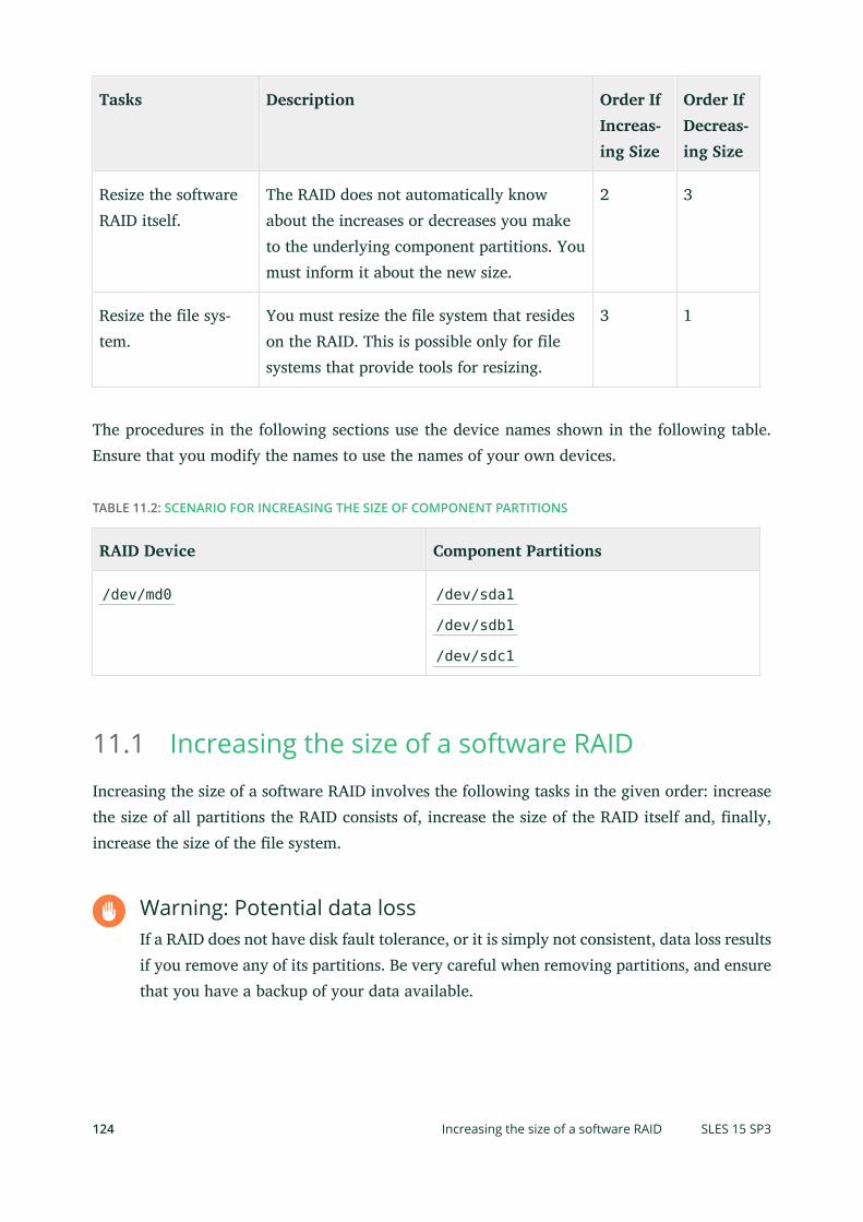
Tasks Description Order IfIncreas-ing Size
Order IfDecreas-ing Size
Resize the softwareRAID itself.
The RAID does not automatically knowabout the increases or decreases you maketo the underlying component partitions. Youmust inform it about the new size.
2 3
Resize the le sys-tem.
You must resize the le system that resideson the RAID. This is possible only for lesystems that provide tools for resizing.
3 1
The procedures in the following sections use the device names shown in the following table.Ensure that you modify the names to use the names of your own devices.
TABLE 11.2: SCENARIO FOR INCREASING THE SIZE OF COMPONENT PARTITIONS
RAID Device Component Partitions
/dev/md0 /dev/sda1
/dev/sdb1
/dev/sdc1
11.1 Increasing the size of a software RAIDIncreasing the size of a software RAID involves the following tasks in the given order: increasethe size of all partitions the RAID consists of, increase the size of the RAID itself and, finally,increase the size of the le system.
Warning: Potential data lossIf a RAID does not have disk fault tolerance, or it is simply not consistent, data loss resultsif you remove any of its partitions. Be very careful when removing partitions, and ensurethat you have a backup of your data available.
124 Increasing the size of a software RAID SLES 15 SP3

11.1.1 Increasing the size of component partitions
Apply the procedure in this section to increase the size of a RAID 1, 4, 5, or 6. For each compo-nent partition in the RAID, remove the partition from the RAID, modify its size, return it to theRAID, then wait until the RAID stabilizes to continue. While a partition is removed, the RAIDoperates in degraded mode and has no or reduced disk fault tolerance. Even for RAIDs that cantolerate multiple concurrent disk failures, do not remove more than one component partition ata time. To increase the size of the component partitions for the RAID, proceed as follows:
1. Open a terminal console.
2. Ensure that the RAID array is consistent and synchronized by entering
> cat /proc/mdstat
If your RAID array is still synchronizing according to the output of this command, youmust wait until synchronization is complete before continuing.
3. Remove one of the component partitions from the RAID array. For example, to remove/dev/sda1 , enter
> sudo mdadm /dev/md0 --fail /dev/sda1 --remove /dev/sda1
To succeed, both the fail and remove actions must be specified.
4. Increase the size of the partition that you removed in the previous step by doing one ofthe following:
Increase the size of the partition, using a disk partitioner such as the YaST Partitioneror the command line tool parted. This option is the usual choice.
Replace the disk on which the partition resides with a higher-capacity device. Thisoption is possible only if no other le systems on the original disk are accessed bythe system. When the replacement device is added back into the RAID, it takes muchlonger to synchronize the data because all of the data that was on the original devicemust be rebuilt.
5. Re-add the partition to the RAID array. For example, to add /dev/sda1 , enter
> sudo mdadm -a /dev/md0 /dev/sda1
Wait until the RAID is synchronized and consistent before continuing with the next par-tition.
125 Increasing the size of component partitions SLES 15 SP3

6. Repeat these steps for each of the remaining component devices in the array. Ensure thatyou modify the commands for the correct component partition.
7. If you get a message that tells you that the kernel could not re-read the partition tablefor the RAID, you must reboot the computer after all partitions have been resized to forcean update of the partition table.
8. Continue with Section 11.1.2, “Increasing the size of the RAID array”.
11.1.2 Increasing the size of the RAID array
After you have resized each of the component partitions in the RAID (see Section 11.1.1, “Increasing
the size of component partitions”), the RAID array configuration continues to use the original arraysize until you force it to be aware of the newly available space. You can specify a size for theRAID or use the maximum available space.
The procedure in this section uses the device name /dev/md0 for the RAID device. Ensure thatyou modify the name to use the name of your own device.
1. Open a terminal console.
2. Ensure that the RAID array is consistent and synchronized by entering
> cat /proc/mdstat
If your RAID array is still synchronizing according to the output of this command, youmust wait until synchronization is complete before continuing.
3. Check the size of the array and the device size known to the array by entering
> sudo mdadm -D /dev/md0 | grep -e "Array Size" -e "Dev Size"
4. Do one of the following:
Increase the size of the array to the maximum available size by entering
> sudo mdadm --grow /dev/md0 -z max
Increase the size of the array to the maximum available size by entering
> sudo mdadm --grow /dev/md0 -z max --assume-clean
126 Increasing the size of the RAID array SLES 15 SP3

The array uses any space that has been added to the devices, but this space will notbe synchronized. This is recommended for RAID 1 because the synchronization isnot needed. It can be useful for other RAID levels if the space that was added to themember devices was pre-zeroed.
Increase the size of the array to a specified value by entering
> sudo mdadm --grow /dev/md0 -z SIZE
Replace SIZE with an integer value in kilobytes (a kilobyte is 1024 bytes) for thedesired size.
5. Recheck the size of your array and the device size known to the array by entering
> sudo mdadm -D /dev/md0 | grep -e "Array Size" -e "Dev Size"
6. Do one of the following:
If your array was successfully resized, continue with Section 11.1.3, “Increasing the size
of the file system”.
If your array was not resized as you expected, you must reboot, then try this proce-dure again.
11.1.3 Increasing the size of the file system
After you increase the size of the array (see Section 11.1.2, “Increasing the size of the RAID array”),you are ready to resize the le system.
You can increase the size of the le system to the maximum space available or specify an exactsize. When specifying an exact size for the le system, ensure that the new size satisfies thefollowing conditions:
The new size must be greater than the size of the existing data; otherwise, data loss occurs.
The new size must be equal to or less than the current RAID size because the le systemsize cannot extend beyond the space available.
Refer to Chapter 2, Resizing file systems for detailed instructions.
127 Increasing the size of the file system SLES 15 SP3

11.2 Decreasing the size of a software RAIDDecreasing the Size of a Software RAID involves the following tasks in the given order: decreasethe size of the le system, decrease the size of all partitions the RAID consists of, and finallydecrease the size of the RAID itself.
Warning: Potential data lossIf a RAID does not have disk fault tolerance, or it is simply not consistent, data loss resultsif you remove any of its partitions. Be very careful when removing partitions, and ensurethat you have a backup of your data available.
Important: XFSDecreasing the size of a le system formatted with XFS is not possible, since such a featureis not supported by XFS. As a consequence, the size of a RAID that uses the XFS le systemcannot be decreased.
11.2.1 Decreasing the size of the file system
When decreasing the size of the le system on a RAID device, ensure that the new size satisfiesthe following conditions:
The new size must be greater than the size of the existing data; otherwise, data loss occurs.
The new size must be equal to or less than the current RAID size because the le systemsize cannot extend beyond the space available.
Refer to Chapter 2, Resizing file systems for detailed instructions.
11.2.2 Decreasing the size of the RAID array
After you have resized the le system (see Section 11.2.1, “Decreasing the size of the file system”), theRAID array configuration continues to use the original array size until you force it to reduce theavailable space. Use the mdadm --grow mode to force the RAID to use a smaller segment size.
128 Decreasing the size of a software RAID SLES 15 SP3

To do this, you must use the -z option to specify the amount of space in kilobytes to use fromeach device in the RAID. This size must be a multiple of the chunk size, and it must leave about128 KB of space for the RAID superblock to be written to the device.
The procedure in this section uses the device name /dev/md0 for the RAID device. Ensure thatyou modify commands to use the name of your own device.
1. Open a terminal console.
2. Check the size of the array and the device size known to the array by entering
> sudo mdadm -D /dev/md0 | grep -e "Array Size" -e "Dev Size"
3. Decrease the array’s device size to a specified value by entering
> sudo mdadm --grow /dev/md0 -z SIZE
Replace SIZE with an integer value in kilobytes for the desired size. (A kilobyte is 1024bytes.)For example, the following command sets the segment size for each RAID device to about40 GB where the chunk size is 64 KB. It includes 128 KB for the RAID superblock.
> sudo mdadm --grow /dev/md2 -z 41943168
4. Recheck the size of your array and the device size known to the array by entering
> sudo mdadm -D /dev/md0 | grep -e "Array Size" -e "Device Size"
5. Do one of the following:
If your array was successfully resized, continue with Section 11.2.3, “Decreasing the size
of component partitions”.
If your array was not resized as you expected, you must reboot, then try this proce-dure again.
11.2.3 Decreasing the size of component partitions
After you decrease the segment size that is used on each device in the RAID (see Section 11.2.2,
“Decreasing the size of the RAID array”), the remaining space in each component partition is notused by the RAID. You can leave partitions at their current size to allow for the RAID to growat a future time, or you can reclaim this now unused space.
129 Decreasing the size of component partitions SLES 15 SP3

To reclaim the space, you decrease the component partitions one at a time. For each componentpartition, you remove it from the RAID, reduce its partition size, return the partition to the RAID,then wait until the RAID stabilizes. To allow for metadata, you should specify a slightly largersize than the size you specified for the RAID in Section 11.2.2, “Decreasing the size of the RAID array”.
While a partition is removed, the RAID operates in degraded mode and has no or reduced diskfault tolerance. Even for RAIDs that can tolerate multiple concurrent disk failures, you shouldnever remove more than one component partition at a time. To decrease the size of the compo-nent partitions for the RAID, proceed as follows:
1. Open a terminal console.
2. Ensure that the RAID array is consistent and synchronized by entering
> cat /proc/mdstat
If your RAID array is still synchronizing according to the output of this command, youmust wait until synchronization is complete before continuing.
3. Remove one of the component partitions from the RAID array. For example, to remove/dev/sda1 , enter
> sudo mdadm /dev/md0 --fail /dev/sda1 --remove /dev/sda1
To succeed, both the fail and remove actions must be specified.
4. Decrease the size of the partition that you removed in the previous step to a size that isslightly larger than the size you set for the segment size. The size should be a multiple ofthe chunk size and allow 128 KB for the RAID superblock. Use a disk partitioner such asthe YaST partitioner or the command line tool parted to decrease the size of the partition.
5. Re-add the partition to the RAID array. For example, to add /dev/sda1 , enter
> sudo mdadm -a /dev/md0 /dev/sda1
Wait until the RAID is synchronized and consistent before continuing with the next par-tition.
6. Repeat these steps for each of the remaining component devices in the array. Ensure thatyou modify the commands for the correct component partition.
7. If you get a message that tells you that the kernel could not re-read the partition table forthe RAID, you must reboot the computer after resizing all of its component partitions.
130 Decreasing the size of component partitions SLES 15 SP3

8. (Optional) Expand the size of the RAID and le system to use the maximum amount ofspace in the now smaller component partitions and increase the size of the le systemafterward. Refer to Section 11.1.2, “Increasing the size of the RAID array” for instructions.
131 Decreasing the size of component partitions SLES 15 SP3

12 Storage enclosure LED utilities for MD softwareRAIDs
Storage enclosure LED Monitoring utility ( ledmon ) and LED Control ( ledctl ) util-ity are Linux user space applications that use a broad range of interfaces and pro-tocols to control storage enclosure LEDs. The primary usage is to visualize the sta-tus of Linux MD software RAID devices created with the mdadm utility. The led-mon daemon monitors the status of the drive array and updates the status of the dri-ve LEDs. The ledctl utility allows you to set LED patterns for specified devices.
These LED utilities use the SGPIO (Serial General Purpose Input/Output) specification (SmallForm Factor (SFF) 8485) and the SCSI Enclosure Services (SES) 2 protocol to control LEDs. Theyimplement the International Blinking Pattern Interpretation (IBPI) patterns of the SFF-8489specification for SGPIO. The IBPI defines how the SGPIO standards are interpreted as states fordrives and slots on a backplane and how the backplane should visualize the states with LEDs.
Some storage enclosures do not adhere strictly to the SFF-8489 specification. An enclosureprocessor might accept an IBPI pattern but not blink the LEDs according to the SFF-8489 spec-ification, or the processor might support only a limited number of the IBPI patterns.
LED management (AHCI) and SAF-TE protocols are not supported by the ledmon and ledctlutilities.
The ledmon and ledctl applications have been verified to work with Intel storage controllerssuch as the Intel AHCI controller and Intel SAS controller. They also support PCIe-SSD (sol-id-state drive) enclosure LEDs to control the storage enclosure status (OK, Fail, Rebuilding) LEDsof PCIe-SSD devices that are part of an MD software RAID volume. The applications might al-so work with the IBPI-compliant storage controllers of other vendors (especially SAS/SCSI con-trollers); however, other vendors’ controllers have not been tested.
ledmon and ledctl are part of the ledmon package, which is not installed by default. Runsudo zypper in ledmon to install it.
132 SLES 15 SP3

12.1 The storage enclosure LED monitor serviceThe ledmon application is a daemon process that constantly monitors the state of MD softwareRAID devices or the state of block devices in a storage enclosure or drive bay. Only a singleinstance of the daemon should be running at a time. The ledmon daemon is part of Intel En-closure LED Utilities.
The state is visualized on LEDs associated with each slot in a storage array enclosure or a drivebay. The application monitors all software RAID devices and visualizes their state. It does notprovide a way to monitor only selected software RAID volumes.
The ledmon daemon supports two types of LED systems: A two-LED system (Activity LED andStatus LED) and a three-LED system (Activity LED, Locate LED, and Fail LED). This tool has thehighest priority when accessing the LEDs.
To start ledmon , enter
> sudo ledmon [options]
where [options] is one or more of the following:
OPTIONS FOR ledmon
-c PATH ,
--confg=PATH
The configuration is read from ~/.ledctl or from /etc/ledcfg.conf if existing. Usethis option to specify an alternative configuration le.Currently this option has no effect, since support for configuration les has not been im-plemented yet. See man 5 ledctl.conf for details.
-l PATH ,
--log= PATH
Sets a path to local log le. If this user-defined le is specified, the global log le /var/log/ledmon.log is not used.
-t SECONDS ,
--interval=SECONDS
Sets the time interval between scans of sysfs . The value is given in seconds. The minimumis 5 seconds. The maximum is not specified.
--quiet , --error , --warning , --info , --debug , --all
133 The storage enclosure LED monitor service SLES 15 SP3

Specifies the verbosity level. The level options are specified in the order of no informationto the most information. Use the --quiet option for no logging. Use the --all optionto log everything. If you specify more than one verbose option, the last option in thecommand applies.
-h ,
--help
Prints the command information to the console, then exits.
-v ,
--version
Displays version of ledmon and information about the license, then exits.
Note: Known issuesThe ledmon daemon does not recognize the PFA (Predicted Failure Analysis) state fromthe SFF-8489 specification. Thus, the PFA pattern is not visualized.
12.2 The storage enclosure LED control applicationThe Enclosure LED Application ( ledctl ) is a user space application that controls LEDs associ-ated with each slot in a storage enclosure or a drive bay. The ledctl application is a part ofIntel Enclosure LED Utilities.
When you issue the command, the LEDs of the specified devices are set to a specified pattern andall other LEDs are turned o. This application needs to be run with root privileges. Because theledmon application has the highest priority when accessing LEDs, some patterns set by ledctlmight have no effect if the ledmon daemon is running (except for the Locate pattern).
The ledctl application supports two types of LED systems: A two-LED system (Activity LEDand Status LED) and a three-LED system (Activity LED, Fail LED, and Locate LED).
To start ledctl , enter
> sudo [options] PATTERN_NAME=list_of_devices
where [options] is one or more of the following:
-c PATH ,
--confg=PATH
134 The storage enclosure LED control application SLES 15 SP3

Sets a path to local configuration le. If this option is specified, the global configurationle and user configuration le have no effect.
-l PATH ,
--log= PATH
Sets a path to local log le. If this user-defined le is specified, the global log le /var/log/ledmon.log is not used.
--quiet
Turns o all messages sent to stdout or stderr out. The messages are still logged tolocal le and the syslog facility.
-h ,
--help
Prints the command information to the console, then exits.
-v ,
--version
Displays version of ledctl and information about the license, then exits.
12.2.1 Pattern names
The ledctl application accepts the following names for pattern_name argument, according tothe SFF-8489 specification.
locate
Turns on the Locate LED associated with the specified devices or empty slots. This stateis used to identify a slot or drive.
locate_off
Turns o the Locate LED associated with the specified devices or empty slots.
normal
Turns o the Status LED, Failure LED, and Locate LED associated with the specified devices.
off
Turns o only the Status LED and Failure LED associated with the specified devices.
ica ,
degraded
135 Pattern names SLES 15 SP3

Visualizes the In a Critical Array pattern.
rebuild ,
rebuild_p
Visualizes the Rebuild pattern. This supports both of the rebuild states for compatibilityand legacy reasons.
ifa ,
failed_array
Visualizes the In a Failed Array pattern.
hotspare
Visualizes the Hotspare pattern.
pfa
Visualizes the Predicted Failure Analysis pattern.
failure ,
disk_failed
Visualizes the Failure pattern.
ses_abort
SES-2 R/R ABORT
ses_rebuild
SES-2 REBUILD/REMAP
ses_ifa
SES-2 IN FAILED ARRAY
ses_ica
SES-2 IN CRITICAL ARRAY
ses_cons_check
SES-2 CONS CHECK
ses_hotspare
SES-2 HOTSPARE
ses_rsvd_dev
SES-2 RSVD DEVICE
ses_ok
136 Pattern names SLES 15 SP3

SES-2 OK
ses_ident
SES-2 IDENT
ses_rm
SES-2 REMOVE
ses_insert
SES-2 INSERT
ses_missing
SES-2 MISSING
ses_dnr
SES-2 DO NOT REMOVE
ses_active
SES-2 ACTIVE
ses_enable_bb
SES-2 ENABLE BYP B
ses_enable_ba
SES-2 ENABLE BYP A
ses_devoff
SES-2 DEVICE OFF
ses_fault
SES-2 FAULT
When a non-SES-2 pattern is sent to a device in an enclosure, the pattern is automatically trans-lated to the SCSI Enclosure Services (SES) 2 pattern as shown above.
TABLE 12.1: TRANSLATION BETWEEN NON-SES-2 PATTERNS AND SES-2 PATTERNS
Non-SES-2 Pattern SES-2 Pattern
locate ses_ident
locate_off ses_ident
normal ses_ok
137 Pattern names SLES 15 SP3
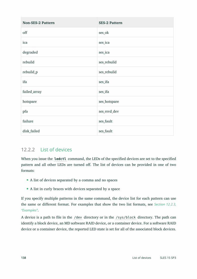
Non-SES-2 Pattern SES-2 Pattern
o ses_ok
ica ses_ica
degraded ses_ica
rebuild ses_rebuild
rebuild_p ses_rebuild
ifa ses_ifa
failed_array ses_ifa
hotspare ses_hotspare
pfa ses_rsvd_dev
failure ses_fault
disk_failed ses_fault
12.2.2 List of devices
When you issue the ledctl command, the LEDs of the specified devices are set to the specifiedpattern and all other LEDs are turned o. The list of devices can be provided in one of twoformats:
A list of devices separated by a comma and no spaces
A list in curly braces with devices separated by a space
If you specify multiple patterns in the same command, the device list for each pattern can usethe same or different format. For examples that show the two list formats, see Section 12.2.3,
“Examples”.
A device is a path to le in the /dev directory or in the /sys/block directory. The path canidentify a block device, an MD software RAID device, or a container device. For a software RAIDdevice or a container device, the reported LED state is set for all of the associated block devices.
138 List of devices SLES 15 SP3
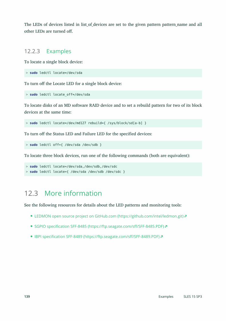
The LEDs of devices listed in list_of_devices are set to the given pattern pattern_name and allother LEDs are turned o.
12.2.3 Examples
To locate a single block device:
> sudo ledctl locate=/dev/sda
To turn o the Locate LED for a single block device:
> sudo ledctl locate_off=/dev/sda
To locate disks of an MD software RAID device and to set a rebuild pattern for two of its blockdevices at the same time:
> sudo ledctl locate=/dev/md127 rebuild={ /sys/block/sd[a-b] }
To turn o the Status LED and Failure LED for the specified devices:
> sudo ledctl off={ /dev/sda /dev/sdb }
To locate three block devices, run one of the following commands (both are equivalent):
> sudo ledctl locate=/dev/sda,/dev/sdb,/dev/sdc> sudo ledctl locate={ /dev/sda /dev/sdb /dev/sdc }
12.3 More informationSee the following resources for details about the LED patterns and monitoring tools:
LEDMON open source project on GitHub.com (https://github.com/intel/ledmon.git)
SGPIO specification SFF-8485 (https://ftp.seagate.com/s/SFF-8485.PDF)
IBPI specification SFF-8489 (https://ftp.seagate.com/s/SFF-8489.PDF)
139 Examples SLES 15 SP3

13 Troubleshooting software RAIDs
Check the /proc/mdstat le to nd out whether a RAID partition has been damaged. If adisk fails, shut down your Linux system and replace the defective hard disk with a new onepartitioned the same way. Then restart your system and enter the command mdadm /dev/mdX--add /dev/sdX . Replace X with your particular device identifiers. This integrates the harddisk automatically into the RAID system and fully reconstructs it (for all RAID levels exceptfor RAID 0).
Although you can access all data during the rebuild, you might encounter some performanceissues until the RAID has been fully rebuilt.
13.1 Recovery after failing disk is back againThere are several reasons a disk included in a RAID array may fail. Here is a list of the mostcommon ones:
Problems with the disk media.
Disk drive controller failure.
Broken connection to the disk.
In the case of disk media or controller failure, the device needs to be replaced or repaired. If ahot spare was not configured within the RAID, then manual intervention is required.
In the last case, the failed device can be automatically re-added with the mdadm command afterthe connection is repaired (which might be automatic).
Because md / mdadm cannot reliably determine what caused the disk failure, it assumes a seriousdisk error and treats any failed device as faulty until it is explicitly told that the device is reliable.
Under some circumstances—such as storage devices with an internal RAID array—connectionproblems are very often the cause of the device failure. In such case, you can tell mdadm thatit is safe to automatically --re-add the device after it appears. You can do this by adding thefollowing line to /etc/mdadm.conf :
POLICY action=re-add
Note that the device will be automatically re-added after re-appearing only if the udev rulescause mdadm -I DISK_DEVICE_NAME to be run on any device that spontaneously appears (de-fault behavior), and if write-intent bitmaps are configured (they are by default).
140 Recovery after failing disk is back again SLES 15 SP3

If you want this policy to only apply to some devices and not to the others, then the path= optioncan be added to the POLICY line in /etc/mdadm.conf to restrict the non-default action to onlyselected devices. Wild cards can be used to identify groups of devices. See man 5 mdadm.conffor more information.
141 Recovery after failing disk is back again SLES 15 SP3

IV Network storage
14 iSNS for Linux 143
15 Mass storage over IP networks: iSCSI 151
16 Fibre Channel storage over Ethernet networks: FCoE 178
17 NVMe over Fabric 189
18 Managing multipath I/O for devices 198
19 Sharing file systems with NFS 261
20 Samba 279
21 On-demand mounting with autofs 303

14 iSNS for Linux
Storage area networks (SANs) can contain many disk drives that are dispersed across complexnetworks. This can make device discovery and device ownership difficult. iSCSI initiators mustbe able to identify storage resources in the SAN and determine whether they have access to them.
Internet Storage Name Service (iSNS) is a standards-based service that simplifies the automat-ed discovery, management, and configuration of iSCSI devices on a TCP/IP network. iSNS pro-vides intelligent storage discovery and management services comparable to those found in FibreChannel networks.
Without iSNS, you must know the host name or IP address of each node where targets of interestare located. In addition, you must manually manage which initiators can access which targetsyourself using mechanisms such as access control lists.
Important: Security considerationsiSNS should only be used in secure internal networking environments, as the networktraffic is not encrypted.
14.1 How iSNS worksFor an iSCSI initiator to discover iSCSI targets, it needs to identify which devices in the networkare storage resources and what IP addresses it needs to access them. A query to an iSNS serverreturns a list of iSCSI targets and the IP addresses that the initiator has permission to access.
Using iSNS, you create iSNS discovery domains into which you then group or organize iSCSI tar-gets and initiators. By dividing storage nodes into domains, you can limit the discovery processof each host to the most appropriate subset of targets registered with iSNS, which allows thestorage network to scale by reducing the number of unnecessary discoveries and by limiting theamount of time each host spends establishing discovery relationships. This lets you control andsimplify the number of targets and initiators that must be discovered.
143 How iSNS works SLES 15 SP3

FIGURE 14.1: ISNS DISCOVERY DOMAINS
Both iSCSI targets and iSCSI initiators can use iSNS clients to initiate transactions with iSNSservers by using the iSNS protocol. They then register device attribute information in a commondiscovery domain, download information about other registered clients, and receive asynchro-nous notification of events that occur in their discovery domain.
iSNS servers respond to iSNS protocol queries and requests made by iSNS clients using theiSNS protocol. iSNS servers initiate iSNS protocol state change notifications and store properlyauthenticated information submitted by a registration request in an iSNS database.
Benefits provided by iSNS for Linux include:
Provides an information facility for registration, discovery, and management of networkedstorage assets.
Integrates with the DNS infrastructure.
Consolidates registration, discovery, and management of iSCSI storage.
Simplifies storage management implementations.
Improves scalability compared to other discovery methods.
iSNS offers several important benefits.
144 How iSNS works SLES 15 SP3

For example, in a setup with 100 iSCSI initiators and 100 iSCSI targets, all iSCSI initiators couldpotentially try to discover and connect to any of the 100 iSCSI targets. By grouping initiatorsand targets into discovery domains, you can prevent iSCSI initiators in one department fromdiscovering the iSCSI targets in another department.
Another advantage of using iSNS is that the iSCSI clients only need to know the host name orIP address of the iSNS server, rather than having to know the host names or IP addresses of ahundred servers.
14.2 Installing iSNS server for LinuxiSNS Server for Linux is included with SUSE Linux Enterprise Server, but is not installed or con-figured by default. You need to install the package open-isns and configure the iSNS service.
Note: iSNS and iSCSI on the same serveriSNS can be installed on the same server where iSCSI target or iSCSI initiator softwareis installed. Installing both the iSCSI target software and iSCSI initiator software on thesame server is not supported.
To install iSNS for Linux:
1. Start YaST and select Network Services iSNS Server.
2. In case open-isns is not installed yet, you are prompted to install it now. Confirm byclicking Install.
3. The iSNS Service configuration dialog opens automatically to the Service tab.
145 Installing iSNS server for Linux SLES 15 SP3

4. In Service Start, select one of the following:
When booting: The iSNS service starts automatically on server start-up.
Manually (default): The iSNS service must be started manually by entering sudosystemctl start isnsd at the server console of the server where you install it.
5. Specify the following firewall settings:
Open port in firewall: Select the check box to open the firewall and allow access tothe service from remote computers. The firewall port is closed by default.
Firewall details: If you open the firewall port, the port is open on all network inter-faces by default. Click Firewall Details to select interfaces on which to open the port,select the network interfaces to use, then click OK.
6. Click OK to apply the configuration settings and complete the installation.
7. Continue with Section 14.3, “Configuring iSNS discovery domains”.
14.3 Configuring iSNS discovery domainsFor iSCSI initiators and targets to use the iSNS service, they must belong to a discovery domain.
146 Configuring iSNS discovery domains SLES 15 SP3

Important: The iSNS service must be activeThe iSNS service must be installed and running to configure iSNS discovery domains. Forinformation, see Section 14.4, “Starting the iSNS service”.
14.3.1 Creating iSNS discovery domains
A default discovery domain named default DD is automatically created when you install theiSNS service. The existing iSCSI targets and initiators that have been configured to use iSNS areautomatically added to the default discovery domain.
To create a new discovery domain:
1. Start YaST and under Network Services, select iSNS Server.
2. Click the Discovery Domains tab.The Discovery Domains area lists all existing discovery domains. You can Create DiscoveryDomains, or Delete existing ones. Keep in mind that deleting an iSCSI node from domainmembership removes it from the domain, but it does not delete the iSCSI node.The Discovery Domain Members area lists all iSCSI nodes assigned to a selected discoverydomain. Selecting a different discovery domain refreshes the list with members from thatdiscovery domain. You can add and delete iSCSI nodes from a selected discovery domain.Deleting an iSCSI node removes it from the domain, but it does not delete the iSCSI node.Create iSCSI Node Member allows a node that is not yet registered to be added as a memberof the discovery domain. When the iSCSI initiator or target registers this node, then itbecomes part of this domain.When an iSCSI initiator performs a discovery request, the iSNS service returns all iSCSInode targets that are members of the same discovery domain.
147 Creating iSNS discovery domains SLES 15 SP3

3. Click the Create Discovery Domain button.You can also select an existing discovery domain and click the Delete button to removethat discovery domain.
4. Specify the name of the discovery domain you are creating, then click OK.
5. Continue with Section 14.3.2, “Adding iSCSI nodes to a discovery domain”.
14.3.2 Adding iSCSI nodes to a discovery domain
1. Start YaST and under Network Services, select iSNS Server.
2. Click the iSCSI Nodes tab.
148 Adding iSCSI nodes to a discovery domain SLES 15 SP3

3. Review the list of nodes to ensure that the iSCSI targets and initiators that you want touse the iSNS service are listed.If an iSCSI target or initiator is not listed, you might need to restart the iSCSI service onthe node. You can do this by running
> sudo systemctl restart iscsid.socket> sudo systemctl restart iscsi
to restart an initiator or
> sudo systemctl restart target-isns
to restart a target.You can select an iSCSI node and click the Delete button to remove that node from theiSNS database. This is useful if you are no longer using an iSCSI node or have renamed it.The iSCSI node is automatically added to the list (iSNS database) again when you restartthe iSCSI service or reboot the server unless you remove or comment out the iSNS portionof the iSCSI configuration le.
4. Click the Discovery Domains tab and select the desired discovery domain.
5. Click Add existing iSCSI Node, select the node you want to add to the domain, then clickAdd Node.
149 Adding iSCSI nodes to a discovery domain SLES 15 SP3

6. Repeat the previous step for as many nodes as you want to add to the discovery domain,then click Done when you are finished adding nodes.Note that an iSCSI node can belong to more than one discovery domain.
14.4 Starting the iSNS serviceiSNS must be started at the server where you install it. If you have not configured it to be startedat boot time (see Section 14.2, “Installing iSNS server for Linux” for details), enter the followingcommand at a terminal console:
> sudo systemctl start isnsd
You can also use the stop , status , and restart options with iSNS.
14.5 More informationThe following projects provide further information on iSNS and iSCSI:
iSNS server and client for Linux project (https://github.com/open-iscsi/open-isns)
iSNS client for the Linux LIO iSCSI target (https://github.com/open-iscsi/target-isns)
iSCSI tools for Linux (http://www.open-iscsi.com)
General information about iSNS is available in RFC 4171: Internet Storage Name Service at https://
tools.ietf.org/html/rfc4171 .
150 Starting the iSNS service SLES 15 SP3

15 Mass storage over IP networks: iSCSI
One of the primary tasks of a computer center, or any site that supports servers, is to provideadequate disk capacity. Fibre Channel is often used for this purpose. iSCSI (Internet SCSI) so-lutions provide a lower-cost alternative to Fibre Channel that can leverage commodity serversand Ethernet networking equipment. Linux iSCSI provides iSCSI initiator and iSCSI LIO targetsoftware for connecting Linux servers to central storage systems.
Server 3 Server 4 Server 5 Server 6Server 1
iSCSIInitiator
Server 2
Ethernet SwitchNetwork Backbone Network Backbone
Ethernet Switch
Ethernet
iSCSIInitiator
iSCSIInitiator
iSCSIInitiator
iSCSIInitiator
iSNSServer
Server 7
iSCSI LIO TargetServer Shared Disks
iSCSI SAN
FIGURE 15.1: ISCSI SAN WITH AN ISNS SERVER
Note: LIOLIO (http://linux-iscsi.org ) is the standard open source multiprotocol SCSI target for Lin-ux. LIO replaced the STGT (SCSI Target) framework as the standard unified storage targetin Linux with Linux kernel version 2.6.38 and later. In SUSE Linux Enterprise Server 12the iSCSI LIO Target Server replaces the iSCSI Target Server from previous versions.
iSCSI is a storage networking protocol that simplifies data transfers of SCSI packets over TCP/IP networks between block storage devices and servers. iSCSI target software runs on the targetserver and defines the logical units as iSCSI target devices. iSCSI initiator software runs ondifferent servers and connects to the target devices to make the storage devices available onthat server.
151 SLES 15 SP3

The iSCSI LIO target server and iSCSI initiator servers communicate by sending SCSI packets atthe IP level in your LAN. When an application running on the initiator server starts an inquiryfor an iSCSI LIO target device, the operating system produces the necessary SCSI commands.The SCSI commands are then embedded in IP packets and encrypted as necessary by softwarethat is commonly known as the iSCSI initiator. The packets are transferred across the internal IPnetwork to the corresponding iSCSI remote station, called the iSCSI LIO target server, or simplythe iSCSI target.
Many storage solutions provide access over iSCSI, but it is also possible to run a Linux serverthat provides an iSCSI target. In this case, it is important to set up a Linux server that is opti-mized for le system services. For more information about RAID, also see Chapter 7, Software
RAID configuration.
15.1 Installing the iSCSI LIO target server and iSCSIinitiatorWhile the iSCSI initiator is installed by default (packages open-iscsi and yast2-isc-si-client ), the iSCSI LIO target packages need to be installed manually.
Important: Initiator and target on the same serverWhile it is possible to run initiator and target in the same system, this setup is not rec-ommended.
To install the iSCSI LIO Target Server, run the following command in a terminal console:
> sudo zypper in yast2-iscsi-lio-server
In case you need to install the iSCSI initiator or any of its dependencies, run the command sudozypper in yast2-iscsi-client .
Alternatively, use the YaST Software Management module for installation.
Any packages required in addition to the ones mentioned above will either be automaticallypulled in by the installer, or be installed when you rst run the respective YaST module.
152 Installing the iSCSI LIO target server and iSCSI initiator SLES 15 SP3

15.2 Setting up an iSCSI LIO target serverThis section describes how to use YaST to configure an iSCSI LIO Target Server and set up iSCSILIO target devices. You can use any iSCSI initiator software to access the target devices.
15.2.1 iSCSI LIO target service start-up and firewall settings
The iSCSI LIO Target service is by default configured to be started manually. You can configurethe service to start automatically at boot time. If you use a firewall on the server and you wantthe iSCSI LIO targets to be available to other computers, you must open a port in the firewallfor each adapter that you want to use for target access. TCP port 3260 is the port number forthe iSCSI protocol, as defined by IANA (Internet Assigned Numbers Authority).
1. Start YaST and launch Network Services iSCSI LIO Target.
2. Switch to the Service tab.
3. Under Service Start, specify how you want the iSCSI LIO target service to be started:
When booting: The service starts automatically on server restart.
Manually: (Default) You must start the service manually after a server restart byrunning sudo systemctl start targetcli . The target devices are not availableuntil you start the service.
153 Setting up an iSCSI LIO target server SLES 15 SP3

4. If you use a firewall on the server and you want the iSCSI LIO targets to be available toother computers, open port 3260 in the firewall for each adapter interface that you wantto use for target access. If the port is closed for all of the network interfaces, the iSCSI LIOtargets are not available to other computers.If you do not use a firewall on the server, the firewall settings are disabled. In this caseskip the following steps and leave the configuration dialog with Finish or switch to anothertab to continue with the configuration.
a. On the Services tab, select the Open Port in Firewall check box to enable the firewallsettings.
b. Click Firewall Details to view or configure the network interfaces to use. All availablenetwork interfaces are listed, and all are selected by default. Deselect all interfaceson which the port should not be opened. Save your settings with OK.
5. Click Finish to save and apply the iSCSI LIO Target service settings.
15.2.2 Configuring authentication for discovery of iSCSI LIO targetsand initiators
The iSCSI LIO Target Server software supports the PPP-CHAP (Point-to-Point Protocol ChallengeHandshake Authentication Protocol), a three-way authentication method defined in the Inter-net Engineering Task Force (IETF) RFC 1994 (https://tools.ietf.org/rfc/rfc1994.txt ). The serveruses this authentication method for the discovery of iSCSI LIO targets and initiators, not foraccessing les on the targets. If you do not want to restrict the access to the discovery, use NoAuthentication. The No Discovery Authentication option is enabled by default. Without requiringauthentication all iSCSI LIO targets on this server can be discovered by any iSCSI initiator onthe same network.
If authentication is needed for a more secure configuration, you can use incoming authentica-tion, outgoing authentication, or both. Authentication by Initiators requires an iSCSI initiator toprove that it has the permissions to run a discovery on the iSCSI LIO target. The initiator mustprovide the incoming user name and password. Authentication by Targets requires the iSCSI LIOtarget to prove to the initiator that it is the expected target. The iSCSI LIO target must providethe outgoing user name and password to the iSCSI initiator. The password needs to be differentfor incoming and outgoing discovery. If authentication for discovery is enabled, its settings ap-ply to all iSCSI LIO target groups.
154 Configuring authentication for discovery of iSCSI LIO targets and initiators SLES 15 SP3

Important: SecurityWe recommend that you use authentication for target and initiator discovery in produc-tion environments for security reasons.
To configure authentication preferences for iSCSI LIO targets:
1. Start YaST and launch Network Services iSCSI LIO Target.
2. Switch to the Global tab.
3. By default, authentication is disabled (No Discovery Authentication). To enable Authenti-cation, select Authentication by Initiators, Outgoing Authentication or both.
4. Provide credentials for the selected authentication method(s). The user name and pass-word pair must be different for incoming and outgoing discovery.
5. Click Finish to save and apply the settings.
155 Configuring authentication for discovery of iSCSI LIO targets and initiators SLES 15 SP3

15.2.3 Preparing the storage space
Before you configure LUNs for your iSCSI Target servers, you must prepare the storage you wantto use. You can use the entire unformatted block device as a single LUN, or you can subdividea device into unformatted partitions and use each partition as a separate LUN. The iSCSI targetconfiguration exports the LUNs to iSCSI initiators.
You can use the Partitioner in YaST or the command line to set up the partitions. Refer toBook “Deployment Guide”, Chapter 10 “Expert Partitioner”, Section 10.1 “Using the Expert Partitioner”
for details. iSCSI LIO targets can use unformatted partitions with Linux, Linux LVM, or LinuxRAID le system IDs.
Important: Do not mount iSCSI target devicesAfter you set up a device or partition for use as an iSCSI target, you never access it directlyvia its local path. Do not mount the partitions on the target server.
15.2.3.1 Partitioning devices in a virtual environment
You can use a virtual machine guest server as an iSCSI LIO Target Server. This section describeshow to assign partitions to a Xen virtual machine. You can also use other virtual environmentsthat are supported by SUSE Linux Enterprise Server.
In a Xen virtual environment, you must assign the storage space you want to use for the iSCSILIO target devices to the guest virtual machine, then access the space as virtual disks withinthe guest environment. Each virtual disk can be a physical block device, such as an entire disk,partition, or volume, or it can be a le-backed disk image where the virtual disk is a singleimage le on a larger physical disk on the Xen host server. For the best performance, createeach virtual disk from a physical disk or a partition. After you set up the virtual disks for theguest virtual machine, start the guest server, then configure the new blank virtual disks as iSCSItarget devices by following the same process as for a physical server.
File-backed disk images are created on the Xen host server, then assigned to the Xen guestserver. By default, Xen stores le-backed disk images in the /var/lib/xen/images/VM_NAMEdirectory, where VM_NAME is the name of the virtual machine.
156 Preparing the storage space SLES 15 SP3

15.2.4 Setting up an iSCSI LIO target group
You can use YaST to configure iSCSI LIO target devices. YaST uses the targetcli software.iSCSI LIO targets can use partitions with Linux, Linux LVM, or Linux RAID le system IDs.
Important: PartitionsBefore you begin, choose the partitions you wish to use for back-end storage. The parti-tions do not have to be formatted—the iSCSI client can format them when connected,overwriting all existing formatting.
1. Start YaST and launch Network Services iSCSI LIO Target.
2. Switch to the Targets tab.
3. Click Add, then define a new iSCSI LIO target group and devices:The iSCSI LIO Target software automatically completes the Target, Identifier, Portal Group,IP Address, and Port Number elds. Use Authentication is selected by default.
a. If you have multiple network interfaces, use the IP address drop-down box to selectthe IP address of the network interface to use for this target group. To make theserver accessible under all addresses, choose Bind All IP Addresses.
157 Setting up an iSCSI LIO target group SLES 15 SP3

b. Deselect Use Authentication if you do not want to require initiator authentication forthis target group (not recommended).
c. Click Add. Enter the path of the device or partition or Browse to add it. Optionallyspecify a name, then click OK. The LUN number is automatically generated, begin-ning with 0. A name is automatically generated if you leave the eld empty.
d. (Optional) Repeat the previous steps to add targets to this target group.
e. After all desired targets have been added to the group, click Next.
4. On the Modify iSCSI Target Initiator Setup page, configure information for the initiators thatare permitted to access LUNs in the target group:
After you specify at least one initiator for the target group, the Edit LUN, Edit Auth, Delete,and Copy buttons are enabled. You can use Add or Copy to add initiators for the targetgroup:
MODIFY ISCSI TARGET: OPTIONS
Add: Add a new initiator entry for the selected iSCSI LIO target group.
158 Setting up an iSCSI LIO target group SLES 15 SP3

Edit LUN: Configure which LUNs in the iSCSI LIO target group to map to a selectedinitiator. You can map each of the allocated targets to a preferred initiator.
Edit auth: Configure the preferred authentication method for a selected initiator.You can specify no authentication, or you can configure incoming authentication,outgoing authentication, or both.
Delete: Remove a selected initiator entry from the list of initiators allocated to thetarget group.
Copy: Add a new initiator entry with the same LUN mappings and authenticationsettings as a selected initiator entry. This allows you to easily allocate the sameshared LUNs, in turn, to each node in a cluster.
a. Click Add, specify the initiator name, select or deselect the Import LUNs from TPGcheck box, then click OK to save the settings.
b. Select an initiator entry, click Edit LUN, modify the LUN mappings to specify whichLUNs in the iSCSI LIO target group to allocate to the selected initiator, then clickOK to save the changes.If the iSCSI LIO target group consists of multiple LUNs, you can allocate one ormultiple LUNs to the selected initiator. By default, each of the available LUNs in thegroup are assigned to an initiator LUN.To modify the LUN allocation, perform one or more of the following actions:
Add: Click Add to create a new Initiator LUN entry, then use the Change drop-down box to map a target LUN to it.
Delete: Select the Initiator LUN entry, then click Delete to remove a target LUNmapping.
Change: Select the Initiator LUN entry, then use the Change drop-down box toselect which Target LUN to map to it.
Typical allocation plans include the following:
A single server is listed as an initiator. All of the LUNs in the target group areallocated to it.
159 Setting up an iSCSI LIO target group SLES 15 SP3
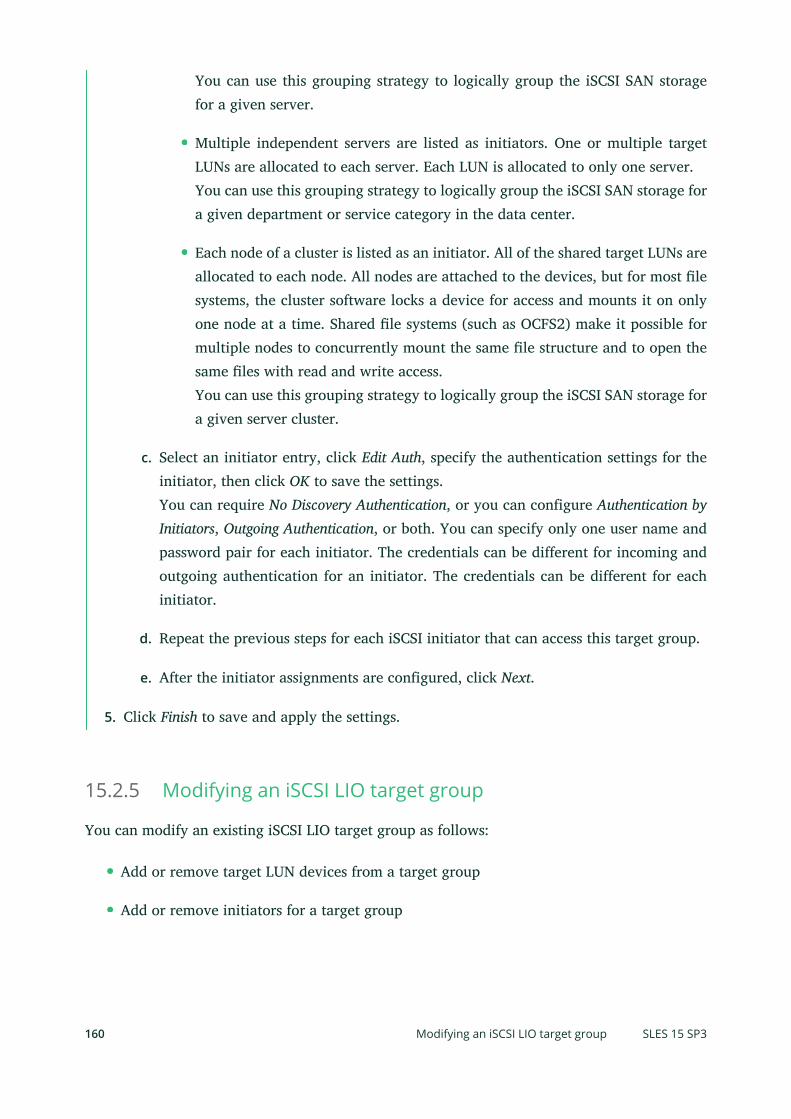
You can use this grouping strategy to logically group the iSCSI SAN storagefor a given server.
Multiple independent servers are listed as initiators. One or multiple targetLUNs are allocated to each server. Each LUN is allocated to only one server.You can use this grouping strategy to logically group the iSCSI SAN storage fora given department or service category in the data center.
Each node of a cluster is listed as an initiator. All of the shared target LUNs areallocated to each node. All nodes are attached to the devices, but for most lesystems, the cluster software locks a device for access and mounts it on onlyone node at a time. Shared le systems (such as OCFS2) make it possible formultiple nodes to concurrently mount the same le structure and to open thesame les with read and write access.You can use this grouping strategy to logically group the iSCSI SAN storage fora given server cluster.
c. Select an initiator entry, click Edit Auth, specify the authentication settings for theinitiator, then click OK to save the settings.You can require No Discovery Authentication, or you can configure Authentication byInitiators, Outgoing Authentication, or both. You can specify only one user name andpassword pair for each initiator. The credentials can be different for incoming andoutgoing authentication for an initiator. The credentials can be different for eachinitiator.
d. Repeat the previous steps for each iSCSI initiator that can access this target group.
e. After the initiator assignments are configured, click Next.
5. Click Finish to save and apply the settings.
15.2.5 Modifying an iSCSI LIO target group
You can modify an existing iSCSI LIO target group as follows:
Add or remove target LUN devices from a target group
Add or remove initiators for a target group
160 Modifying an iSCSI LIO target group SLES 15 SP3

Modify the initiator LUN-to-target LUN mappings for an initiator of a target group
Modify the user name and password credentials for an initiator authentication (incoming,outgoing, or both)
To view or modify the settings for an iSCSI LIO target group:
1. Start YaST and launch Network Services iSCSI LIO Target.
2. Switch to the Targets tab.
3. Select the iSCSI LIO target group to be modified, then click Edit.
4. On the Modify iSCSI Target LUN Setup page, add LUNs to the target group, edit the LUNassignments, or remove target LUNs from the group. After all desired changes have beenmade to the group, click Next.For option information, see Modify iSCSI target: options.
5. On the Modify iSCSI Target Initiator Setup page, configure information for the initiatorsthat are permitted to access LUNs in the target group. After all desired changes have beenmade to the group, click Next.
6. Click Finish to save and apply the settings.
15.2.6 Deleting an iSCSI LIO target group
Deleting an iSCSI LIO target group removes the definition of the group, and the related setup forinitiators, including LUN mappings and authentication credentials. It does not destroy the dataon the partitions. To give initiators access again, you can allocate the target LUNs to a differentor new target group, and configure the initiator access for them.
1. Start YaST and launch Network Services iSCSI LIO Target.
2. Switch to the Targets tab.
3. Select the iSCSI LIO target group to be deleted, then click Delete.
4. When you are prompted, click Continue to confirm the deletion, or click Cancel to cancel it.
5. Click Finish to save and apply the settings.
161 Deleting an iSCSI LIO target group SLES 15 SP3

15.3 Configuring iSCSI initiatorThe iSCSI initiator can be used to connect to any iSCSI target. This is not restricted to the iSCSItarget solution explained in Section 15.2, “Setting up an iSCSI LIO target server”. The configuration ofiSCSI initiator involves two major steps: the discovery of available iSCSI targets and the setupof an iSCSI session. Both can be done with YaST.
15.3.1 Using YaST for the iSCSI initiator configuration
The iSCSI Initiator Overview in YaST is divided into three tabs:
Service:
The Service tab can be used to enable the iSCSI initiator at boot time. It also offers to seta unique Initiator Name and an iSNS server to use for the discovery.
Connected targets:
The Connected Targets tab gives an overview of the currently connected iSCSI targets. Likethe Discovered Targets tab, it also gives the option to add new targets to the system.
Discovered targets:
The Discovered Targets tab provides the possibility of manually discovering iSCSI targetsin the network.
15.3.1.1 Configuring the iSCSI initiator
1. Start YaST and launch Network Services iSCSI Initiator.
2. Switch to the Service tab.
162 Configuring iSCSI initiator SLES 15 SP3

3. Under After writing configuration, define what to do if there is a configuration change. Bearin mind that available options depend on the service current status.The Keep current state option keeps the service in the same status.
4. In the After reboot menu specify action that will take place after reboot:
Start on boot - to start the service automatically on boot.
Start on demand - the associated socket will be running and if needed, the servicewill be started.
Do not start - the service is not started automatically.
Keep current settings - the service configuration is not changed.
5. Specify or verify the Initiator Name.Specify a well-formed iSCSI qualified name (IQN) for the iSCSI initiator on this server.The initiator name must be globally unique on your network. The IQN uses the followinggeneral format:
iqn.yyyy-mm.com.mycompany:n1:n2
where n1 and n2 are alphanumeric characters. For example:
iqn.1996-04.de.suse:01:a5dfcea717a
163 Using YaST for the iSCSI initiator configuration SLES 15 SP3

The Initiator Name is automatically completed with the corresponding value from the /etc/iscsi/initiatorname.iscsi le on the server.If the server has iBFT (iSCSI Boot Firmware Table) support, the Initiator Name is completedwith the corresponding value in the IBFT, and you are not able to change the initiator namein this interface. Use the BIOS Setup to modify it instead. The iBFT is a block of informationcontaining various parameters useful to the iSCSI boot process, including iSCSI target andinitiator descriptions for the server.
6. Use either of the following methods to discover iSCSI targets on the network.
iSNS: To use iSNS (Internet Storage Name Service) for discovering iSCSI targets,continue with Section 15.3.1.2, “Discovering iSCSI targets by using iSNS”.
Discovered targets: To discover iSCSI target devices manually, continue with Sec-
tion 15.3.1.3, “Discovering iSCSI targets manually”.
15.3.1.2 Discovering iSCSI targets by using iSNS
Before you can use this option, you must have already installed and configured an iSNS serverin your environment. For information, see Chapter 14, iSNS for Linux.
1. In YaST, select iSCSI Initiator, then select the Service tab.
2. Specify the IP address of the iSNS server and port. The default port is 3205.
3. Click OK to save and apply your changes.
15.3.1.3 Discovering iSCSI targets manually
Repeat the following process for each of the iSCSI target servers that you want to access fromthe server where you are setting up the iSCSI initiator.
1. In YaST, select iSCSI Initiator, then select the Discovered Targets tab.
2. Click Discovery to open the iSCSI Initiator Discovery dialog.
3. Enter the IP address and change the port if needed. The default port is 3260.
4. If authentication is required, deselect No Discovery Authentication, then specify the creden-tials for Authentication by Initiator or Authentication by Targets.
164 Using YaST for the iSCSI initiator configuration SLES 15 SP3

5. Click Next to start the discovery and connect to the iSCSI target server.
6. If credentials are required, after a successful discovery, use Connect to activate the target.You are prompted for authentication credentials to use the selected iSCSI target.
7. Click Next to finish the configuration.The target now appears in Connected Targets and the virtual iSCSI device is now available.
8. Click OK to save and apply your changes.
9. You can nd the local device path for the iSCSI target device by using the lsscsi com-mand.
15.3.1.4 Setting the start-up preference for iSCSI target devices
1. In YaST, select iSCSI Initiator, then select the Connected Targets tab to view a list of theiSCSI target devices that are currently connected to the server.
2. Select the iSCSI target device that you want to manage.
3. Click Toggle Start-Up to modify the setting:
Automatic: This option is used for iSCSI targets that are to be connected when the iSCSIservice itself starts up. This is the typical configuration.
Onboot: This option is used for iSCSI targets that are to be connected during boot; thatis, when root ( / ) is on iSCSI. As such, the iSCSI target device will be evaluated from theinitrd on server boots. This option is ignored on platforms that cannot boot from iSCSI,such as IBM Z. Therefore it should not be used on these platforms; use Automatic instead.
4. Click OK to save and apply your changes.
15.3.2 Setting up the iSCSI initiator manually
Both the discovery and the configuration of iSCSI connections require a running iscsid. Whenrunning the discovery the rst time, the internal database of the iSCSI initiator is created in thedirectory /etc/iscsi/ .
165 Setting up the iSCSI initiator manually SLES 15 SP3

If your discovery is password protected, provide the authentication information to iscsid. Be-cause the internal database does not exist when doing the rst discovery, it cannot be used now.Instead, the configuration le /etc/iscsid.conf must be edited to provide the information.To add your password information for the discovery, add the following lines to the end of /etc/iscsid.conf :
discovery.sendtargets.auth.authmethod = CHAPdiscovery.sendtargets.auth.username = USERNAMEdiscovery.sendtargets.auth.password = PASSWORD
The discovery stores all received values in an internal persistent database. In addition, it displaysall detected targets. Run this discovery with the following command:
> sudo iscsiadm -m discovery --type=st --portal=TARGET_IP
The output should look like the following:
10.44.171.99:3260,1 iqn.2006-02.com.example.iserv:systems
To discover the available targets on an iSNS server, use the following command:
sudo iscsiadm --mode discovery --type isns --portal TARGET_IP
For each target defined on the iSCSI target, one line appears. For more information about thestored data, see Section 15.3.3, “The iSCSI initiator databases”.
The special --login option of iscsiadm creates all needed devices:
> sudo iscsiadm -m node -n iqn.2006-02.com.example.iserv:systems --login
The newly generated devices show up in the output of lsscsi and can now be mounted.
15.3.3 The iSCSI initiator databases
All information that was discovered by the iSCSI initiator is stored in two database les thatreside in /etc/iscsi . There is one database for the discovery of targets and one for the dis-covered nodes. When accessing a database, you rst must select if you want to get your datafrom the discovery or from the node database. Do this with the -m discovery and -m nodeparameters of iscsiadm . Using iscsiadm with one of these parameters gives an overview ofthe stored records:
> sudo iscsiadm -m discovery10.44.171.99:3260,1 iqn.2006-02.com.example.iserv:systems
166 The iSCSI initiator databases SLES 15 SP3

The target name in this example is iqn.2006-02.com.example.iserv:systems . This name isneeded for all actions that relate to this special data set. To examine the content of the datarecord with the ID iqn.2006-02.com.example.iserv:systems , use the following command:
> sudo iscsiadm -m node --targetname iqn.2006-02.com.example.iserv:systemsnode.name = iqn.2006-02.com.example.iserv:systemsnode.transport_name = tcpnode.tpgt = 1node.active_conn = 1node.startup = manualnode.session.initial_cmdsn = 0node.session.reopen_max = 32node.session.auth.authmethod = CHAPnode.session.auth.username = joenode.session.auth.password = ********node.session.auth.username_in = EMPTYnode.session.auth.password_in = EMPTYnode.session.timeo.replacement_timeout = 0node.session.err_timeo.abort_timeout = 10node.session.err_timeo.reset_timeout = 30node.session.iscsi.InitialR2T = Nonode.session.iscsi.ImmediateData = Yes....
To edit the value of one of these variables, use the command iscsiadm with the update op-eration. For example, if you want iscsid to log in to the iSCSI target when it initializes, set thevariable node.startup to the value automatic :
sudo iscsiadm -m node -n iqn.2006-02.com.example.iserv:systems \-p ip:port --op=update --name=node.startup --value=automatic
Remove obsolete data sets with the delete operation. If the target iqn.2006-02.com.exam-ple.iserv:systems is no longer a valid record, delete this record with the following command:
> sudo iscsiadm -m node -n iqn.2006-02.com.example.iserv:systems \-p ip:port --op=delete
Important: No confirmationUse this option with caution because it deletes the record without any additional confir-mation prompt.
To get a list of all discovered targets, run the sudo iscsiadm -m node command.
167 The iSCSI initiator databases SLES 15 SP3

15.4 Setting up software targets using targetcli-fbtargetcli is a shell for managing the configuration of the LinuxIO (LIO) target subsystem.The shell can be called interactively, or you can execute one command at a time, much likea conventional shell. Similar to a conventional shell, you can traverse the targetcli functionalhierarchy using the cd command and list contents with the ls command.
The available commands depend on the current directory. While each directory has its own setof commands, there are also commands that are available in all directories (for example, thecd and ls commands).
targetcli commands have the following format:
[DIRECTORY] command [ARGUMENTS]
You can use the help command in any directory to view a list of available commands or infor-mation about any command in particular.
The targetcli tool is part of the targetcli-fb package. This package is available in theofficial SUSE Linux Enterprise Server software repository, and it can be installed using the fol-lowing command:
> sudo zypper install targetcli-fb
After the targetcli-fb package has been installed, enable the targetcli service:
> sudo systemctl enable targetcli> sudo systemctl start targetcli
To switch to the targetcli shell, run the targetcli as root:
> sudo targetcli
You can then run the ls command to see the default configuration.
/> lso- / ............................ [...] o- backstores ................. [...] | o- block ..... [Storage Objects: 0] | o- fileio .... [Storage Objects: 0] | o- pscsi ..... [Storage Objects: 0] | o- ramdisk ... [Storage Objects: 0] | o- rbd ....... [Storage Objects: 0] o- iscsi ............... [Targets: 0] o- loopback ............ [Targets: 0] o- vhost ............... [Targets: 0]
168 Setting up software targets using targetcli-fb SLES 15 SP3

o- xen-pvscsi .......... [Targets: 0]/>
As the output of the ls command indicates, there are no configured back-ends. So the rst stepis to configure one of the supported software targets.
targetcli supports the following back-ends:
fileio , local image le
block , block storage on a dedicated disk or partition
pscsi , SCSI pass-through devices
ramdisk , memory-based back-end
rbd , Ceph RADOS block devices
To familiarize yourself with the functionality of targetcli, set up a local image le as a softwaretarget using the create command:
/backstores/fileio create test-disc /alt/test.img 1G
This creates a 1 GB test.img image in the specified location (in this case /alt ). Run ls , andyou should see the following result:
/> lso- / ........................................................... [...] o- backstores ................................................ [...] | o- block .................................... [Storage Objects: 0] | o- fileio ................................... [Storage Objects: 1] | | o- test-disc ... [/alt/test.img (1.0GiB) write-back deactivated] | | o- alua ...... .......................... [ALUA Groups: 1] | | o- default_tg_pt_gp .... [ALUA state: Active/optimized] | o- pscsi .................................... [Storage Objects: 0] | o- ramdisk .................................. [Storage Objects: 0] | o- rbd ...................................... [Storage Objects: 0] o- iscsi .............................................. [Targets: 0] o- loopback ........................................... [Targets: 0] o- vhost .............................................. [Targets: 0] o- xen-pvscsi ......................................... [Targets: 0]/>
The output indicates that there is now a le-based backstore, under the /backstores/fileiodirectory, called test-disc , which is linked to the created le /alt/test.img . Note that thenew backstore is not yet activated.
169 Setting up software targets using targetcli-fb SLES 15 SP3

The next step is to connect an iSCSI target front-end to the back-end storage. Each target musthave an IQN (iSCSI Qualified Name). The most commonly used IQN format is as follows:
iqn.YYYY-MM.NAMING-AUTHORITY:UNIQUE-NAME
The following parts of an IQN are required:
YYYY-MM , the year and month when the naming authority was established
NAMING-AUTHORITY , reverse-syntax of the Internet Domain Name of the naming authority
UNIQUE-NAME , a domain-unique name chosen by the naming authority
For example, for the domain open-iscsi.com , the IQN can be as follows:
iqn.2005-03.com.open-iscsi:UNIQUE-NAME
When creating an iSCSI target, the targetcli command allows you to assign your own IQN,as long as it follows the specified format. You can also let the command create an IQN for youby omitting a name when creating the target, for example:
/> iscsi/ create
Run the ls command again:
/> lso- / ............................................................... [...] o- backstores .................................................... [...] | o- block ........................................ [Storage Objects: 0] | o- fileio ....................................... [Storage Objects: 1] | | o- test-disc ....... [/alt/test.img (1.0GiB) write-back deactivated] | | o- alua ......................................... [ALUA Groups: 1] | | o- default_tg_pt_gp ............. [ALUA state: Active/optimized] | o- pscsi ........................................ [Storage Objects: 0] | o- ramdisk ...................................... [Storage Objects: 0] | o- rbd .......................................... [Storage Objects: 0] o- iscsi .................................................. [Targets: 1] | o- iqn.2003-01.org.linux-iscsi.e83.x8664:sn.8b35d04dd456 ... [TPGs: 1] | o- tpg1 ..................................... [no-gen-acls, no-auth] | o- acls ................................................ [ACLs: 0] | o- luns ................................................ [LUNs: 0] | o- portals .......................................... [Portals: 1] | o- 0.0.0.0:3260 ........................................... [OK] o- loopback ............................................... [Targets: 0] o- vhost .................................................. [Targets: 0] o- xen-pvscsi ............................................. [Targets: 0]/>
170 Setting up software targets using targetcli-fb SLES 15 SP3

The output shows the created iSCSI target node with its automatically generated IQNiqn.2003-01.org.linux-iscsi.e83.x8664:sn.8b35d04dd456
Note that targetcli has also created and enabled the default target portal group tpg1 . Thisis done because the variables auto_add_default_portal and auto_enable_tpgt at the rootlevel are set to true by default.
The command also created the default portal with the 0.0.0.0 IPv4 wildcard. This means thatany IPv4 address can access the configured target.
The next step is to create a LUN (Logical Unit Number) for the iSCSI target. The best way todo this is to let targetcli assign its name and number automatically. Switch to the directoryof the iSCSI target, and then use the create command in the lun directory to assign a LUNto the backstore.
/> cd /iscsi/iqn.2003-01.org.linux-iscsi.e83.x8664:sn.8b35d04dd456//iscsi/iqn.2003-01.org.linux-iscsi.e83.x8664:sn.8b35d04dd456> cd tpg1/iscsi/iqn.2003-01.org.linux-iscsi.e83.x8664:sn.8b35d04dd456/tpg1> luns/create /backstores/fileio/test-disc
Run the ls command to see the changes:
/iscsi/iqn.2003-01.org.linux-iscsi.e83.x8664:sn.8b35d04dd456/tpg1> lso- tpg1 .............................................. [no-gen-acls, no-auth] o- acls ..................................................... [ACLs: 0] o- luns ..................................................... [LUNs: 1] | o- lun0 ....... [fileio/test-disc (/alt/test.img) (default_tg_pt_gp)] o- portals ............................................... [Portals: 1] o- 0.0.0.0:3260 ................................................ [OK]
There is now an iSCSI target that has a 1 GB le-based backstore. The target has theiqn.2003-01.org.linux-iscsi.e83.x8664:sn.8b35d04dd456 name, and it can be accessedfrom any network port of the system.
Finally, you need to ensure that initiators have access to the configured target. One way to dothis is to create an ACL rule for each initiator that allows them to connect to the target. In thiscase, you must list each desired initiator using its IQN. The IQNs of the existing initiators canbe found in the /etc/iscsi/initiatorname.iscsi le. Use the following command to addthe desired initiator (in this case, it's iqn.1996-04.de.suse:01:54cab487975b ):
/iscsi/iqn.2003-01.org.linux-iscsi.e83.x8664:sn.8b35d04dd456/tpg1> acls/ create iqn.1996-04.de.suse:01:54cab487975bCreated Node ACL for iqn.1996-04.de.suse:01:54cab487975bCreated mapped LUN 0./iscsi/iqn.2003-01.org.linux-iscsi.e83.x8664:sn.8b35d04dd456/tpg1>
171 Setting up software targets using targetcli-fb SLES 15 SP3

Alternatively, you can run the target in a demo mode with no access restrictions. This methodis less secure, but it can be useful for demonstration purposes and running on closed networks.To enable the demo mode, use the following commands:
/iscsi/iqn.2003-01.org.linux-iscsi.e83.x8664:sn.8b35d04dd456/tpg1> set attribute generate_node_acls=1/iscsi/iqn.2003-01.org.linux-iscsi.e83.x8664:sn.8b35d04dd456/tpg1> set attribute demo_mode_write_protect=0
The last step is to save the created configuration using the saveconfig command available inthe root directory:
/> saveconfig /etc/target/example.json
If at some point you need to restore configuration from the saved le, you need to clear thecurrent configuration rst. Keep in mind that clearing the current configuration results in dataloss unless you save your configuration rst. Use the following command to clear and reloadthe configuration:
/> clearconfigAs a precaution, confirm=True needs to be set/> clearconfig confirm=trueAll configuration cleared/> restoreconfig /etc/target/example.jsonConfiguration restored from /etc/target/example.json/>
To test whether the configured target is working, connect to it using the open-iscsi iSCSI ini-tiator installed on the same system (replace HOSTNAME with the host name of the local machine):
> iscsiadm -m discovery -t st -p HOSTNAME
This command returns a list of found targets, for example:
192.168.20.3:3260,1 iqn.2003-01.org.linux-iscsi.e83.x8664:sn.8b35d04dd456
You can then connect to the listed target using the login iSCSI command. This makes the targetavailable as a local disk.
15.5 Using iSCSI disks when installingBooting from an iSCSI disk on AMD64/Intel 64 and IBM POWER architectures is supported wheniSCSI-enabled rmware is used.
172 Using iSCSI disks when installing SLES 15 SP3

To use iSCSI disks during installation, it is necessary to add the following parameter to the bootparameter line:
withiscsi=1
During installation, an additional screen appears that provides the option to attach iSCSI disksto the system and use them in the installation process.
Note: Mount point supportiSCSI devices will appear asynchronously during the boot process. While the initrd guar-antees that those devices are set up correctly for the root le system, there are no suchguarantees for any other le systems or mount points like /usr . Hence any system mountpoints like /usr or /var are not supported. To use those devices, ensure correct syn-chronization of the respective services and devices.
15.6 Troubleshooting iSCSIThis section describes some known issues and possible solutions for iSCSI target and iSCSI ini-tiator issues.
15.6.1 Portal error when setting up target LUNs on an iSCSI LIOtarget server
When adding or editing an iSCSI LIO target group, you get an error:
Problem setting network portal IP_ADDRESS:3260
The /var/log/YasT2/y2log log le contains the following error:
find: `/sys/kernel/config/target/iscsi': No such file or directory
This problem occurs if the iSCSI LIO Target Server software is not currently running. To resolvethis issue, exit YaST, manually start iSCSI LIO at the command line with systemctl starttargetcli , then try again.
You can also enter the following to check if configfs , iscsi_target_mod , and tar-get_core_mod are loaded. A sample response is shown.
> sudo lsmod | grep iscsi
173 Troubleshooting iSCSI SLES 15 SP3

iscsi_target_mod 295015 0target_core_mod 346745 4iscsi_target_mod,target_core_pscsi,target_core_iblock,target_core_fileconfigfs 35817 3 iscsi_target_mod,target_core_modscsi_mod 231620 16iscsi_target_mod,target_core_pscsi,target_core_mod,sg,sr_mod,mptctl,sd_mod,scsi_dh_rdac,scsi_dh_emc,scsi_dh_alua,scsi_dh_hp_sw,scsi_dh,libata,mptspi,mptscsih,scsi_transport_spi
15.6.2 iSCSI LIO targets are not visible from other computers
If you use a firewall on the target server, you must open the iSCSI port that you are using toallow other computers to see the iSCSI LIO targets. For information, see Section 15.2.1, “iSCSI LIO
target service start-up and firewall settings”.
15.6.3 Data packets dropped for iSCSI trac
A firewall might drop packets if it gets too busy. The default for the SUSE Firewall is to droppackets after three minutes. If you nd that iSCSI traffic packets are being dropped, considerconfiguring the SUSE Firewall to queue packets instead of dropping them when it gets too busy.
15.6.4 Using iSCSI volumes with LVM
Use the troubleshooting tips in this section when using LVM on iSCSI targets.
15.6.4.1 Check if the iSCSI initiator discovery occurs at boot
When you set up the iSCSI Initiator, ensure that you enable discovery at boot time so that udevcan discover the iSCSI devices at boot time and set up the devices to be used by LVM.
15.6.4.2 Check that iSCSI target discovery occurs at boot
Remember that udev provides the default setup for devices. Ensure that all of the applicationsthat create devices are started at boot time so that udev can recognize and assign devices forthem at system start-up. If the application or service is not started until later, udev does notcreate the device automatically as it would at boot time.
174 iSCSI LIO targets are not visible from other computers SLES 15 SP3

15.6.5 iSCSI targets are mounted when the configuration file is setto manual
When Open-iSCSI starts, it can mount the targets even if the node.startup option is set tomanual in the /etc/iscsi/iscsid.conf le if you manually modified the configuration le.
Check the /etc/iscsi/nodes/TARGET_NAME/IP_ADDRESS,PORT/default le. It contains anode.startup setting that overrides the /etc/iscsi/iscsid.conf le. Setting the mountoption to manual by using the YaST interface also sets node.startup = manual in the /etc/iscsi/nodes/TARGET_NAME/IP_ADDRESS,PORT/default les.
15.7 iSCSI LIO target terminology
backstore
A physical storage object that provides the actual storage underlying an iSCSI endpoint.
CDB (command descriptor block)
The standard format for SCSI commands. CDBs are commonly 6, 10, or 12 bytes long,though they can be 16 bytes or of variable length.
CHAP (challenge handshake authentication protocol)
A point-to-point protocol (PPP) authentication method used to confirm the identity of onecomputer to another. After the Link Control Protocol (LCP) connects the two computers,and the CHAP method is negotiated, the authenticator sends a random Challenge to thepeer. The peer issues a cryptographically hashed Response that depends upon the Chal-lenge and a secret key. The authenticator verifies the hashed Response against its owncalculation of the expected hash value, and either acknowledges the authentication or ter-minates the connection. CHAP is defined in the RFC 1994.
CID (connection identifier)
A 16‐bit number, generated by the initiator, that uniquely identifies a connection betweentwo iSCSI devices. This number is presented during the login phase.
endpoint
The combination of an iSCSI Target Name with an iSCSI TPG (IQN + Tag).
EUI (extended unique identifier)
175 iSCSI targets are mounted when the configuration file is set to manual SLES 15 SP3

A 64‐bit number that uniquely identifies every device in the world. The format consistsof 24 bits that are unique to a given company, and 40 bits assigned by the company toeach device it builds.
initiator
The originating end of an SCSI session. Typically a controlling device such as a computer.
IPS (Internet protocol storage)
The class of protocols or devices that use the IP protocol to move data in a storage network.FCIP (Fibre Channel over Internet Protocol), iFCP (Internet Fibre Channel Protocol), andiSCSI (Internet SCSI) are all examples of IPS protocols.
IQN (iSCSI qualified name)
A name format for iSCSI that uniquely identifies every device in the world (for example:iqn.5886.com.acme.tapedrive.sn‐a12345678 ).
ISID (initiator session identifier)
A 48‐bit number, generated by the initiator, that uniquely identifies a session between theinitiator and the target. This value is created during the login process, and is sent to thetarget with a Login PDU.
MCS (multiple connections per session)
A part of the iSCSI specification that allows multiple TCP/IP connections between an ini-tiator and a target.
MPIO (multipath I/O)
A method by which data can take multiple redundant paths between a server and storage.
network portal
The combination of an iSCSI endpoint with an IP address plus a TCP (Transmission ControlProtocol) port. TCP port 3260 is the port number for the iSCSI protocol, as defined byIANA (Internet Assigned Numbers Authority).
SAM (SCSI architectural model)
A document that describes the behavior of SCSI in general terms, allowing for differenttypes of devices communicating over various media.
target
The receiving end of an SCSI session, typically a device such as a disk drive, tape drive,or scanner.
target group (TG)
176 iSCSI LIO target terminology SLES 15 SP3

A list of SCSI target ports that are all treated the same when creating views. Creating aview can help simplify LUN (logical unit number) mapping. Each view entry specifies atarget group, host group, and a LUN.
target port
The combination of an iSCSI endpoint with one or more LUNs.
target port group (TPG)
A list of IP addresses and TCP port numbers that determines which interfaces a specificiSCSI target will listen to.
target session identifier (TSID)
A 16‐bit number, generated by the target, that uniquely identifies a session between theinitiator and the target. This value is created during the login process, and is sent to theinitiator with a Login Response PDU (protocol data units).
15.8 More informationThe iSCSI protocol has been available for several years. There are many reviews comparingiSCSI with SAN solutions, benchmarking performance, and there also is documentation describ-ing hardware solutions. For more information, see the Open-iSCSI project home page at http://
www.open-iscsi.com/ .
Additionally, see the man pages for iscsiadm , iscsid , and the example configuration le /etc/iscsid.conf .
177 More information SLES 15 SP3

16 Fibre Channel storage over Ethernet networks:FCoE
Many enterprise data centers rely on Ethernet for their LAN and data traffic, and on Fibre Chan-nel networks for their storage infrastructure. Open Fibre Channel over Ethernet (FCoE) Initiatorsoftware allows servers with Ethernet adapters to connect to a Fibre Channel storage subsystemover an Ethernet network. This connectivity was previously reserved exclusively for systemswith Fibre Channel adapters over a Fibre Channel fabric. The FCoE technology reduces com-plexity in the data center by aiding network convergence. This helps to preserve your existinginvestments in a Fibre Channel storage infrastructure and to simplify network management.
Ethernet Card(s)
10 Gbps Ethernet Card(s)
Server 1 Server 2 Server 3 Server 4 Server 5 Server 6
Open FCoEInitiator
Lossless Ethernet
Open FCoEInitiator
Open FCoEInitiator
Open FCoEInitiator
Open FCoEInitiator
Open FCoEInitiator
10 Gbps Ethernet Switch with Fibre Channel Forwarder
Fibre Channelover Ethernet
SAN
Fibre Channel
Network Backbone
Ethernet
Network BackboneEthernet Switch
FC Storage Arrays
FC Switch
Fibre Channel SAN
FIGURE 16.1: OPEN FIBRE CHANNEL OVER ETHERNET SAN
Open-FCoE allows you to run the Fibre Channel protocols on the host, instead of on propri-etary hardware on the host bus adapter. It is targeted for 10 Gbps (gigabit per second) Ether-net adapters, but can work on any Ethernet adapter that supports pause frames. The initiatorsoftware provides a Fibre Channel protocol processing module and an Ethernet-based transportmodule. The Open-FCoE module acts as a low-level driver for SCSI. The Open-FCoE transportuses net_device to send and receive packets. Data Center Bridging (DCB) drivers provide thequality of service for FCoE.
178 SLES 15 SP3

FCoE is an encapsulation protocol that moves the Fibre Channel protocol traffic over Ethernetconnections without changing the Fibre Channel frame. This allows your network security andtraffic management infrastructure to work the same with FCoE as it does with Fibre Channel.
You might choose to deploy FCoE in your enterprise if the following conditions exist:
Your enterprise already has a Fibre Channel storage subsystem and administrators withFibre Channel skills and knowledge.
You are deploying 10 Gbps Ethernet in the network.
This section describes how to set up FCoE in your network.
16.1 Configuring FCoE interfaces during theinstallationThe YaST installation for SUSE Linux Enterprise Server allows you to configure FCoE disks duringthe operating system installation if FCoE is enabled at the switch for the connections between theserver and the Fibre Channel storage infrastructure. Some system BIOS types can automaticallydetect the FCoE disks, and report the disks to the YaST Installation software. However, automaticdetection of FCoE disks is not supported by all BIOS types. To enable automatic detection inthis case, you can add the withfcoe option to the kernel command line when you begin theinstallation:
withfcoe=1
When the FCoE disks are detected, the YaST installation offers the option to configure FCoEinstances at that time. On the Disk Activation page, select Configure FCoE Interfaces to accessthe FCoE configuration. For information about configuring the FCoE interfaces, see Section 16.3,
“Managing FCoE services with YaST”.
179 Configuring FCoE interfaces during the installation SLES 15 SP3

Note: Mount point supportFCoE devices will appear asynchronously during the boot process. While the initrd guar-antees that those devices are set up correctly for the root le system, there are no suchguarantees for any other le systems or mount points like /usr . Hence any system mountpoints like /usr or /var are not supported. To use those devices, ensure correct syn-chronization of the respective services and devices.
16.2 Installing FCoE and the YaST FCoE clientYou can set up FCoE disks in your storage infrastructure by enabling FCoE at the switch forthe connections to a server. If FCoE disks are available when the SUSE Linux Enterprise Serveroperating system is installed, the FCoE Initiator software is automatically installed at that time.
If the FCoE Initiator software and the YaST FCoE Client software are not installed, use thefollowing procedure to manually install them with the following command:
> sudo zypper in yast2-fcoe-client fcoe-utils
Alternatively, use the YaST Software Manager to install the packages listed above.
180 Installing FCoE and the YaST FCoE client SLES 15 SP3

16.3 Managing FCoE services with YaSTYou can use the YaST FCoE Client Configuration option to create, configure, and remove FCoEinterfaces for the FCoE disks in your Fibre Channel storage infrastructure. To use this option,the FCoE Initiator service (the fcoemon daemon) and the Link Layer Discovery Protocol agentdaemon ( llpad ) must be installed and running, and the FCoE connections must be enabled atthe FCoE-capable switch.
1. Launch YaST and select Network Services FCoE Client Configuration.
2. On the Services tab, view or modify the FCoE service and Lldpad (Link Layer DiscoveryProtocol agent daemon) service start time as necessary.
FCoE service start: Specifies whether to start the Fibre Channel over Ethernet servicefcoemon daemon at the server boot time or manually. The daemon controls theFCoE interfaces and establishes a connection with the llpad daemon. The valuesare When Booting (default) or Manually.
Lldpad service start: Specifies whether to start the Link Layer Discovery Protocolagent llpad daemon at the server boot time or manually. The llpad daemon in-forms the fcoemon daemon about the Data Center Bridging features and the config-uration of the FCoE interfaces. The values are When Booting (default) or Manually.
181 Managing FCoE services with YaST SLES 15 SP3

If you modify a setting, click OK to save and apply the change.
3. On the Interfaces tab, view information about all of the detected network adapters on theserver, including information about VLAN and FCoE configuration. You can also create anFCoE VLAN interface, change settings for an existing FCoE interface, or remove an FCoEinterface.
Use the FCoE VLAN Interface column to determine whether FCoE is available or not:
Interface Name
If a name is assigned to the interface, such as eth4.200 , FCoE is available on theswitch, and the FCoE interface is activated for the adapter.
Not configured:
If the status is not configured, FCoE is enabled on the switch, but an FCoE interfacehas not been activated for the adapter. Select the adapter, then click Create FCoEVLAN Interface to activate the interface on the adapter.
Not available:
If the status is not available, FCoE is not possible for the adapter because FCoE hasnot been enabled for that connection on the switch.
4. To set up an FCoE-enabled adapter that has not yet been configured, select it and clickCreate FCoE VLAN Interface. Confirm the query with Yes.The adapter is now listed with an interface name in the FCoE VLAN Interface column.
5. To change the settings for an adapter that is already configured, select it from the list,then click Change Settings.
182 Managing FCoE services with YaST SLES 15 SP3

The following options can be configured:
FCoE enable
Enable or disable the creation of FCoE instances for the adapter.
DCB required
Specifies whether Data Center Bridging is required for the adapter (usually this isthe case).
Auto VLAN
Specifies whether the fcoemon daemon creates the VLAN interfaces automatically.
If you modify a setting, click Next to save and apply the change. The settings are writtento the /etc/fcoe/cfg-ethX le. The fcoemon daemon reads the configuration les foreach FCoE interface when it is initialized.
6. To remove an interface that is already configured, select it from the list. Click RemoveInterface and Continue to confirm. The FCoE Interface value changes to not configured.
7. On the Configuration tab, view or modify the general settings for the FCoE system ser-vice. You can enable or disable debugging messages from the FCoE service script and thefcoemon daemon and specify whether messages are sent to the system log.
183 Managing FCoE services with YaST SLES 15 SP3

8. Click OK to save and apply changes.
16.4 Configuring FCoE with commands
1. Open a terminal console.
2. Use YaST to configure the Ethernet network interface card, such as eth2 .
3. Start the Link Layer Discovery Protocol agent daemon ( llpad ).
> sudo systemctl start lldpad
4. Enable Data Center Bridging on your Ethernet adapter.
> dcbtool sc eth2 dcb on Version: 2 Command: Set Config Feature: DCB State Port: eth2 Status: Successful
5. Enable and set the Priority Flow Control (PFC) settings for Data Center Bridging.
> sudo dcbtool sc eth<x> pfc e:1 a:1 w:1
Argument setting values are:
e:<0|1>
Controls feature enablement.
a:<0|1>
Controls whether the feature is advertised via Data Center Bridging Exchange pro-tocol to the peer.
w:<0|1>
Controls whether the feature is willing to change its operational configuration basedon what is received from the peer.
6. Enable the Data Center Bridging to accept the switch’s priority setting for FCoE.
> sudo dcbtool sc eth2 app:fcoe e:1 Version: 2
184 Configuring FCoE with commands SLES 15 SP3

Command: Set Config Feature: Application FCoE Port: eth2 Status: Successful
7. Copy the default FCoE configuration le to /etc/fcoe/cfg-eth2 .
> sudo cp /etc/fcoe/cfg-ethx /etc/fcoe/cfg-eth2
8. Start the FCoE Initiator service.
systemctl start fcoe.service
9. Set up the Link Layer Discovery Protocol agent daemon ( llpad ) and the FCoE Initiatorservice to start when booting.
> systemctl enable llpad fcoe
16.5 Managing FCoE instances with the FCoEadministration toolThe fcoeadm utility is the Fibre Channel over Ethernet (FCoE) management tool. It can be usedto create, destroy, and reset an FCoE instance on a given network interface. The fcoeadm utilitysends commands to a running fcoemon process via a socket interface. For information aboutfcoemon , see the man 8 fcoemon .
The fcoeadm utility allows you to query the FCoE instances about the following:
Interfaces
Target LUNs
Port statistics
The fcoeadm utility is part of the fcoe-utils package. The general syntax for the commandlooks like the following:
fcoeadm [-c|--create] [<ethX>] [-d|--destroy] [<ethX>] [-r|--reset] [<ethX>]
185 Managing FCoE instances with the FCoE administration tool SLES 15 SP3
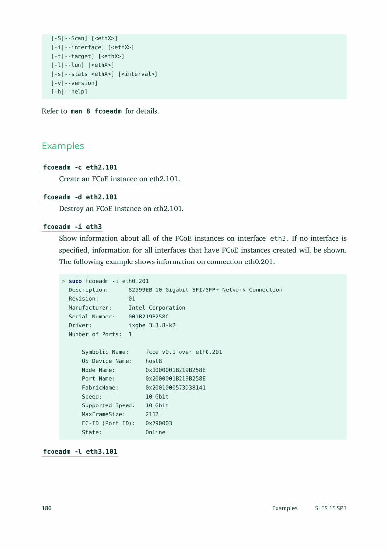
[-S|--Scan] [<ethX>] [-i|--interface] [<ethX>] [-t|--target] [<ethX>] [-l|--lun] [<ethX>] [-s|--stats <ethX>] [<interval>] [-v|--version] [-h|--help]
Refer to man 8 fcoeadm for details.
Examples
fcoeadm -c eth2.101
Create an FCoE instance on eth2.101.
fcoeadm -d eth2.101
Destroy an FCoE instance on eth2.101.
fcoeadm -i eth3
Show information about all of the FCoE instances on interface eth3 . If no interface isspecified, information for all interfaces that have FCoE instances created will be shown.The following example shows information on connection eth0.201:
> sudo fcoeadm -i eth0.201 Description: 82599EB 10-Gigabit SFI/SFP+ Network Connection Revision: 01 Manufacturer: Intel Corporation Serial Number: 001B219B258C Driver: ixgbe 3.3.8-k2 Number of Ports: 1
Symbolic Name: fcoe v0.1 over eth0.201 OS Device Name: host8 Node Name: 0x1000001B219B258E Port Name: 0x2000001B219B258E FabricName: 0x2001000573D38141 Speed: 10 Gbit Supported Speed: 10 Gbit MaxFrameSize: 2112 FC-ID (Port ID): 0x790003 State: Online
fcoeadm -l eth3.101
186 Examples SLES 15 SP3
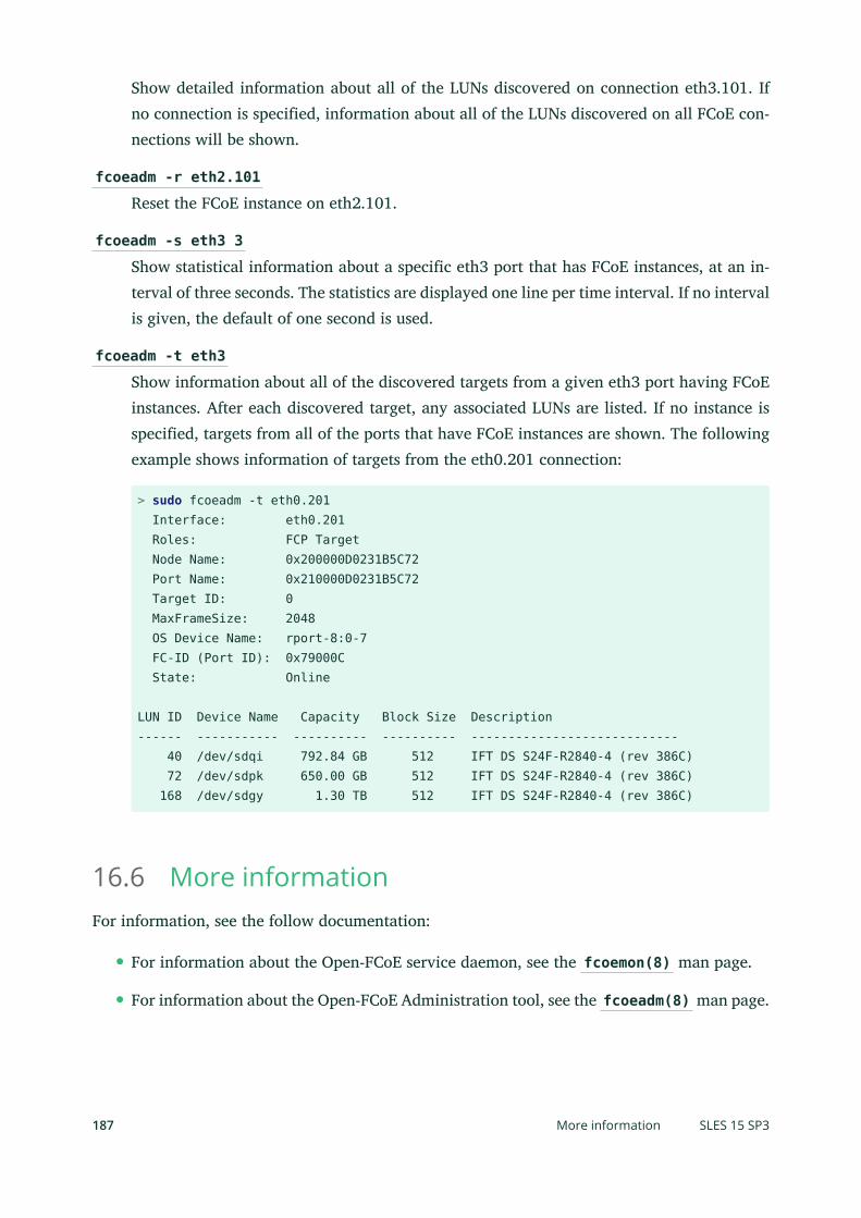
Show detailed information about all of the LUNs discovered on connection eth3.101. Ifno connection is specified, information about all of the LUNs discovered on all FCoE con-nections will be shown.
fcoeadm -r eth2.101
Reset the FCoE instance on eth2.101.
fcoeadm -s eth3 3
Show statistical information about a specific eth3 port that has FCoE instances, at an in-terval of three seconds. The statistics are displayed one line per time interval. If no intervalis given, the default of one second is used.
fcoeadm -t eth3
Show information about all of the discovered targets from a given eth3 port having FCoEinstances. After each discovered target, any associated LUNs are listed. If no instance isspecified, targets from all of the ports that have FCoE instances are shown. The followingexample shows information of targets from the eth0.201 connection:
> sudo fcoeadm -t eth0.201 Interface: eth0.201 Roles: FCP Target Node Name: 0x200000D0231B5C72 Port Name: 0x210000D0231B5C72 Target ID: 0 MaxFrameSize: 2048 OS Device Name: rport-8:0-7 FC-ID (Port ID): 0x79000C State: Online
LUN ID Device Name Capacity Block Size Description------ ----------- ---------- ---------- ---------------------------- 40 /dev/sdqi 792.84 GB 512 IFT DS S24F-R2840-4 (rev 386C) 72 /dev/sdpk 650.00 GB 512 IFT DS S24F-R2840-4 (rev 386C) 168 /dev/sdgy 1.30 TB 512 IFT DS S24F-R2840-4 (rev 386C)
16.6 More informationFor information, see the follow documentation:
For information about the Open-FCoE service daemon, see the fcoemon(8) man page.
For information about the Open-FCoE Administration tool, see the fcoeadm(8) man page.
187 More information SLES 15 SP3

For information about the Data Center Bridging Configuration tool, see the dcbtool(8)man page.
For information about the Link Layer Discovery Protocol agent daemon, see the lld-pad(8) man page.
188 More information SLES 15 SP3

17 NVMe over Fabric
This chapter describes how to set up an NVMe over Fabric host and target.
17.1 OverviewNVM Express (NVMe) is an interface standard for accessing non-volatile storage, commonly SSDdisks. NVMe supports much higher speeds and has a lower latency than SATA.
NVMe over Fabric is an architecture to access NVMe storage over different networking fabrics—for example, RDMA, TCP, or NVMe over Fibre Channel (FC-NVMe). The role of NVMe over Fab-ric is similar to iSCSI. To increase the fault-tolerance, NVMe over Fabric has a built-in supportfor multipathing. The NVMe over Fabric multipathing is not based on the traditional DM-Mul-tipathing.
The NVMe host is the machine that connects to an NVMe target. The NVMe target is the machinethat shares its NVMe block devices.
NVMe is supported on SUSE Linux Enterprise Server 15 SP3. There are Kernel modules availablefor the NVMe block storage and NVMe over Fabric target and host.
To see if your hardware requires any special consideration, refer to Section 17.4, “Special hardware
configuration”.
17.2 Setting up an NVMe over Fabric hostTo use NVMe over Fabric, a target must be available with one of the supported networkingmethods. Supported are NVMe over Fibre Channel, TCP, and RDMA. The following sectionsdescribe how to connect a host to an NVMe target.
17.2.1 Installing command line client
To use NVMe over Fabric, you need the nvme command line tool. Install it with zypper :
> sudo zypper in nvme-cli
Use nvme --help to list all available subcommands. Man pages are available for nvme sub-commands. Consult them by executing man nvme-SUBCOMMAND . For example, to view the manpage for the discover subcommand, execute man nvme-discover .
189 Overview SLES 15 SP3

17.2.2 Discovering NVMe over Fabric targets
To list available NVMe subsystems on the NVMe over Fabric target, you need the discoverycontroller address and service ID.
> sudo nvme discover -t TRANSPORT -a DISCOVERY_CONTROLLER_ADDRESS -s SERVICE_ID
Replace TRANSPORT with the underlying transport medium: loop , rdma , tcp , or fc . ReplaceDISCOVERY_CONTROLLER_ADDRESS with the address of the discovery controller. For RDMA andTCP, this should be an IPv4 address. Replace SERVICE_ID with the transport service ID. If theservice is IP based, like RDMA or TCP, service ID specifies the port number. For Fibre Channel,the service ID is not required.
The NVMe hosts only see the subsystems they are allowed to connect to.
Example:
> sudo nvme discover -t tcp -a 10.0.0.3 -s 4420
For more details, see man nvme-discover .
17.2.3 Connecting to NVMe over Fabric targets
After you have identified the NVMe subsystem, you can connect it with the nvme connectcommand.
> sudo nvme connect -t transport -a DISCOVERY_CONTROLLER_ADDRESS -s SERVICE_ID -n SUBSYSTEM_NQN
Replace TRANSPORT with the underlying transport medium: loop , rdma , tcp or fc . ReplaceDISCOVERY_CONTROLLER_ADDRESS with the address of the discovery controller. For RDMA andTCP this should be an IPv4 address. Replace SERVICE_ID with the transport service ID. If theservice is IP based, like RDMA or TCP, this specifies the port number. Replace SUBSYSTEM_NQNwith the NVMe qualified name of the desired subsystem as found by the discovery command.NQN is the abbreviation for NVMe Qualified Name. The NQN must be unique.
Example:
> sudo nvme connect -t tcp -a 10.0.0.3 -s 4420 -n nqn.2014-08.com.example:nvme:nvm-subsystem-sn-d78432
Alternatively, use nvme connect-all to connect to all discovered namespaces. For advancedusage see man nvme-connect and man nvme-connect-all .
190 Discovering NVMe over Fabric targets SLES 15 SP3

In case of a path loss, the NVMe subsytem tries to reconnect for a time period, defined bythe ctrl-loss-tmo option of the nvme connect command. After this time (default value is600s), the path is removed and the upper layers of the block layer (le system) are notified. Bydefault, the le system is then mounted read-only, which usually is not the expected behaviour.Therefore, it is recommended to set the ctrl-loss-tmo option so that the NVMe subsytemkeeps trying to reconnect without a limit. To do so, run the following command:
> sudo nvme connect --ctrl-loss-tmo=-1
To make an NVMe over Fabrics subsytem available at boot, create a /etc/nvme/discov-ery.conf le on the host with the parameters passed to the discover command (as describedin Section 17.2.2, “Discovering NVMe over Fabric targets”. For example, if you use the discovercommand as follows:
> sudo nvme discover -t tcp -a 10.0.0.3 -s 4420
Add the parameters of the discover command to the /etc/nvme/discovery.conf le:
echo "-t tcp -a 10.0.0.3 -s 4420" | sudo tee -a /etc/nvme/discovery.conf
Then enable the nvmf-autoconnect service:
> sudo systemctl enable nvmf-autoconnect.service
17.2.4 Multipathing
NVMe native multipathing is enabled by default. If the CMIC option in the controller identitysettings is set, the NVMe stack recognizes an NVME drive as a multipathed device by default.
To manage the multipathing, you can use the following:
MANAGING MULTIPATHING
nvme list-subsys
Prints the layout of the multipath devices.
multipath -ll
The command has a compatibility mode and displays NVMe multipath devices.
nvme-core.multipath=N
When the option is added as a boot parameter, the NVMe native multipathing will bedisabled.
191 Multipathing SLES 15 SP3
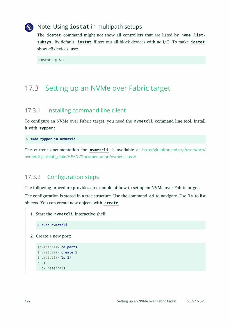
Note: Using iostat in multipath setupsThe iostat command might not show all controllers that are listed by nvme list-subsys . By default, iostat filters out all block devices with no I/O. To make iostatshow all devices, use:
iostat -p ALL
17.3 Setting up an NVMe over Fabric target
17.3.1 Installing command line client
To configure an NVMe over Fabric target, you need the nvmetcli command line tool. Installit with zypper :
> sudo zypper in nvmetcli
The current documentation for nvmetcli is available at http://git.infradead.org/users/hch/
nvmetcli.git/blob_plain/HEAD:/Documentation/nvmetcli.txt .
17.3.2 Configuration steps
The following procedure provides an example of how to set up an NVMe over Fabric target.
The configuration is stored in a tree structure. Use the command cd to navigate. Use ls to listobjects. You can create new objects with create .
1. Start the nvmetcli interactive shell:
> sudo nvmetcli
2. Create a new port:
(nvmetcli)> cd ports(nvmetcli)> create 1(nvmetcli)> ls 1/o- 1 o- referrals
192 Setting up an NVMe over Fabric target SLES 15 SP3

o- subsystems
3. Create an NVMe subsystem:
(nvmetcli)> cd /subsystems(nvmetcli)> create nqn.2014-08.org.nvmexpress:NVMf:uuid:c36f2c23-354d-416c-95de-f2b8ec353a82(nvmetcli)> cd nqn.2014-08.org.nvmexpress:NVMf:uuid:c36f2c23-354d-416c-95de-f2b8ec353a82/(nvmetcli)> lso- nqn.2014-08.org.nvmexpress:NVMf:uuid:c36f2c23-354d-416c-95de-f2b8ec353a82 o- allowed_hosts o- namespaces
4. Create a new namespace and set an NVMe device to it:
(nvmetcli)> cd namespaces(nvmetcli)> create 1(nvmetcli)> cd 1(nvmetcli)> set device path=/dev/nvme0n1Parameter path is now '/dev/nvme0n1'.
5. Enable the previously created namespace:
(nvmetcli)> cd ..(nvmetcli)> enableThe Namespace has been enabled.
6. Display the created namespace:
(nvmetcli)> cd ..(nvmetcli)> lso- nqn.2014-08.org.nvmexpress:NVMf:uuid:c36f2c23-354d-416c-95de-f2b8ec353a82 o- allowed_hosts o- namespaces o- 1
7. Allow all hosts to use the subsystem. Only do this in secure environments.
(nvmetcli)> set attr allow_any_host=1Parameter allow_any_host is now '1'.
Alternatively, you can allow only specific hosts to connect:
(nvmetcli)> cd nqn.2014-08.org.nvmexpress:NVMf:uuid:c36f2c23-354d-416c-95de-f2b8ec353a82/allowed_hosts/
193 Configuration steps SLES 15 SP3

(nvmetcli)> create hostnqn
8. List all created objects:
(nvmetcli)> cd /(nvmetcli)> lso- / o- hosts o- ports | o- 1 | o- referrals | o- subsystems o- subsystems o- nqn.2014-08.org.nvmexpress:NVMf:uuid:c36f2c23-354d-416c-95de-f2b8ec353a82 o- allowed_hosts o- namespaces o- 1
9. Make the target available via TCP. Use trtype=rdma for RDMA:
(nvmetcli)> cd ports/1/(nvmetcli)> set addr adrfam=ipv4 trtype=tcp traddr=10.0.0.3 trsvcid=4420Parameter trtype is now 'tcp'.Parameter adrfam is now 'ipv4'.Parameter trsvcid is now '4420'.Parameter traddr is now '10.0.0.3'.
Alternatively, you can make it available with Fibre Channel:
(nvmetcli)> cd ports/1/(nvmetcli)> set addr adrfam=fc trtype=fc traddr=nn-0x1000000044001123:pn-0x2000000055001123 trsvcid=none
10. Link the subsystem to the port:
(nvmetcli)> cd /ports/1/subsystems(nvmetcli)> create nqn.2014-08.org.nvmexpress:NVMf:uuid:c36f2c23-354d-416c-95de-f2b8ec353a82
Now you can verify that the port is enabled using dmesg :
# dmesg ...[ 257.872084] nvmet_tcp: enabling port 1 (10.0.0.3:4420)
194 Configuration steps SLES 15 SP3

17.3.3 Back up and restore target configuration
You can save the target configuration in a JSON le with the following commands:
> sudo nvmetcli(nvmetcli)> saveconfig nvme-target-backup.json
To restore the configuration, use:
(nvmetcli)> restore nvme-target-backup.json
You can also wipe the current configuration:
(nvmetcli)> clear
17.4 Special hardware configuration
17.4.1 Overview
Some hardware needs special configuration to work correctly. Skim the titles of the followingsections to see if you are using any of the mentioned devices or vendors.
17.4.2 Broadcom
If you are using the Broadcom Emulex LightPulse Fibre Channel SCSI driver, add a Kernel config-uration parameter on the target and host for the lpfc module:
> sudo echo "options lpfc lpfc_enable_fc4_type=3" > /etc/modprobe.d/lpfc.conf
Make sure that the Broadcom adapter rmware has at least version 11.4.204.33. Also make surethat you have the current versions of nvme-cli , nvmetcli and the Kernel installed.
To enable a Fibre Channel port as an NVMe target, an additional module parameter needs tobe configured: lpfc_enable_nvmet= COMMA_SEPARATED_WWPNS . Enter the WWPN with a lead-ing 0x , for example lpfc_enable_nvmet=0x2000000055001122,0x2000000055003344 . Onlylisted WWPNs will be configured for target mode. A Fibre Channel port can either be configuredas target or as initiator.
195 Back up and restore target configuration SLES 15 SP3

17.4.3 Marvell
FC-NVMe is supported on QLE269x and QLE27xx adapters. FC-NVMe support is enabled bydefault in the Marvell® QLogic® QLA2xxx Fibre Channel driver.
To confirm NVMe is enabled, run the following command:
> cat /sys/module/qla2xxx/parameters/ql2xnvmeenable
A resulting 1 means NVMe is enabled, a 0 indicates it is disabled.
Next, ensure that the Marvell adapter rmware is at least version 8.08.204 by checking theoutput of the following command:
> cat /sys/class/scsi_host/host0/fw_version
Last, ensure that the latest versions available for SUSE Linux Enterprise Server of nvme-cli ,QConvergeConsoleCLI , and the Kernel are installed. You may, for example, run
# zypper lu && zypper pchk
to check for updates and patches.
For more details on installation, please refer to the FC-NVMe sections in the following Marvelluser guides:
http://
driverdownloads.qlogic.com/QLogicDriverDownloads_UI/ShowEula.aspx?resourcei-
d=32769&docid=96728&ProductCategory=39&Product=1259&Os=126
http://
driverdownloads.qlogic.com/QLogicDriverDownloads_UI/ShowEula.aspx?resourcei-
d=32761&docid=96726&ProductCategory=39&Product=1261&Os=126
17.5 More informationFor more details about the abilities of the nvme command, refer to nvme nvme-help .
The following links provide a basic introduction to NVMe and NVMe over Fabric:
http://nvmexpress.org/
http://www.nvmexpress.org/wp-content/uploads/NVMe_Over_Fabrics.pdf
196 Marvell SLES 15 SP3

https://storpool.com/blog/demystifying-what-is-nvmeof
https://medium.com/@metebalci/a-quick-tour-of-nvm-express-nvme-3da2246ce4ef
197 More information SLES 15 SP3

18 Managing multipath I/O for devices
This section describes how to manage failover and path load balancing for multiple paths be-tween the servers and block storage devices by using Multipath I/O (MPIO).
18.1 Understanding multipath I/OMultipathing is the ability of a server to communicate with the same physical or logical blockstorage device across multiple physical paths between the host bus adapters in the server and thestorage controllers for the device, typically in Fibre Channel (FC) or iSCSI SAN environments.You can also achieve multiple connections with direct attached storage when multiple channelsare available.
Linux multipathing provides connection fault tolerance and can provide load balancing acrossthe active connections. When multipathing is configured and running, it automatically isolatesand identifies device connection failures, and reroutes I/O to alternate connections.
Typical connection problems involve faulty adapters, cables, or controllers. When you configuremultipath I/O for a device, the multipath driver monitors the active connection between devices.When the multipath driver detects I/O errors for an active path, it fails over the traffic to thedevice’s designated secondary path. When the preferred path becomes healthy again, controlcan be returned to the preferred path.
18.2 Hardware supportThe multipathing drivers and tools support all architectures for which SUSE Linux EnterpriseServer is available. They support most storage arrays. The storage array that houses the multi-pathed device must support multipathing to use the multipathing drivers and tools. Some storagearray vendors provide their own multipathing management tools. Consult the vendor’s hardwaredocumentation to determine what settings are required.
198 Understanding multipath I/O SLES 15 SP3

18.2.1 Storage arrays that are automatically detected formultipathing
The multipath-tools package automatically detects the following storage arrays:
3PARdata VVAIX NVDISKAIX VDASDAPPLE Xserve RAIDCOMPELNT Compellent VolCOMPAQ/HP HSV101, HSV111, HSV200, HSV210, HSV300, HSV400, HSV 450COMPAQ/HP MSA, HSVCOMPAQ/HP MSA VOLUMEDataCore SANmelodyDDN SAN DataDirectorDEC HSG80DELL MD3000DELL MD3000iDELL MD32xxDELL MD32xxiDGCEMC ClariionEMC InvistaEMC SYMMETRIXEUROLOGC FC2502FSC CentricStorFUJITSU ETERNUS_DX, DXL, DX400, DX8000HITACHI DFHITACHI/HP OPENHP A6189AHP HSVX700HP LOGICAL VOLUMEHP MSA2012fc, MSA 2212fc, MSA2012iHP MSA2012sa, MSA2312 fc/i/sa, MCA2324 fc/i/sa, MSA2000s VOLUMEHP P2000 G3 FC|P2000G3 FC/iSCSI|P2000 G3 SAS|P2000 G3 iSCSIIBM 1722-600IBM 1724
199 Storage arrays that are automatically detected for multipathing SLES 15 SP3

IBM 1726IBM 1742IBM 1745, 1746IBM 1750500IBM 1814IBM 1815IBM 1818IBM 1820N00IBM 2105800IBM 2105F20IBM 2107900IBM 2145IBM 2810XIVIBM 3303 NVDISKIBM 3526IBM 3542IBM IPRIBM NseriesIBM ProFibre 4000RIBM S/390 DASD ECKDIBM S/390 DASD FBAIntel Multi-FlexLSI/ENGENIO INF-01-00NEC DISK ARRAYNETAPP LUNNEXENTA COMSTARPillar AxiomPIVOT3 RAIGE VOLUMESGI ISSGI TP9100, TP 9300SGI TP9400, TP9500STK FLEXLINE 380STK OPENstorage D280SUN CSM200_RSUN LCSM100_[IEFS]SUN STK6580, STK6780
200 Storage arrays that are automatically detected for multipathing SLES 15 SP3

SUN StorEdge 3510, T4SUN SUN_6180
In general, most other storage arrays should work. When storage arrays are automatically de-tected, the default settings for multipathing apply. If you want non-default settings, you mustmanually create and configure the /etc/multipath.conf le. The same applies for hardwarethat is not automatically detected. For information, see Section 18.6, “Creating or modifying the /
etc/multipath.conf file”.
Consider the following caveats:
Not all of the storage arrays that are automatically detected have been tested on SUSE LinuxEnterprise Server. Also see Section 18.2.2, “Tested storage arrays for multipathing support”.
Some storage arrays might require specific hardware handlers. A hardware handler is akernel module that performs hardware-specific actions when switching path groups anddealing with I/O errors. For information, see Section 18.2.3, “Storage arrays that require specific
hardware handlers”.
After each modification of the /etc/multipath.conf le, you must run dracut -f tore-create the initrd on your system. Reboot afterward for the changes to take effect.
18.2.2 Tested storage arrays for multipathing support
Storage arrays from the following vendors have been tested with SUSE Linux Enterprise Server:
EMCHitachiHewlett-Packard/CompaqIBMNetAppSGI
Most other vendor storage arrays should also work. Consult your vendor’s documentation forguidance. For a list of the default storage arrays recognized by the multipath-tools package,see Section 18.2.1, “Storage arrays that are automatically detected for multipathing”.
201 Tested storage arrays for multipathing support SLES 15 SP3

18.2.3 Storage arrays that require specific hardware handlers
Storage arrays that require special commands on failover from one path to the other or thatrequire special nonstandard error handling might require more extensive support. Therefore,the Device Mapper Multipath service has hooks for hardware handlers. For example, one suchhandler for the EMC CLARiiON CX family of arrays is already provided.
Important: More informationConsult the hardware vendor’s documentation to determine if its hardware handler mustbe installed for Device Mapper Multipath.
The multipath -t command shows an internal table of storage arrays that require specialhandling with specific hardware handlers. The displayed list is not an exhaustive list of support-ed storage arrays. It lists only those arrays that require special handling and that the multi-path-tools developers had access to during the tool development.
Important: ExceptionsArrays with true active/active multipath support do not require special handling, so theyare not listed for the multipath -t command.
A listing in the multipath -t table does not necessarily mean that SUSE Linux EnterpriseServer was tested on that specific hardware. For a list of tested storage arrays, see Section 18.2.2,
“Tested storage arrays for multipathing support”.
18.3 Planning for multipathingUse the guidelines in this section when planning your multipath I/O solution.
18.3.1 Prerequisites
Multipathing is managed at the device level.
The storage array you use for the multipathed device must support multipathing. For moreinformation, see Section 18.2, “Hardware support”.
202 Storage arrays that require specific hardware handlers SLES 15 SP3

You need to configure multipathing only if multiple physical paths exist between host busadapters in the server and host bus controllers for the block storage device. You configuremultipathing for the logical device as seen by the server.
For some storage arrays, the vendor provides its own multipathing software to managemultipathing for the array’s physical and logical devices. In this case, you should followthe vendor’s instructions for configuring multipathing for those devices.
When using multipathing in a virtualization environment, the multipathing is controlledin the host server environment. Configure multipathing for the device before you assignit to a virtual guest machine.
18.3.2 Disk management tasks
Perform the following disk management tasks before you attempt to configure multipathing fora physical or logical device that has multiple paths:
Use third-party tools to carve physical disks into smaller logical disks.
Use third-party tools to partition physical or logical disks. If you change the partitioning inthe running system, the Device Mapper Multipath (DM-MP) module does not automaticallydetect and reflect these changes. DM-MPIO must be re-initialized, which usually requiresa reboot.
Use third-party SAN array management tools to create and configure hardware RAID de-vices.
Use third-party SAN array management tools to create logical devices such as LUNs. Logicaldevice types that are supported for a given array depend on the array vendor.
18.3.3 Software RAIDs
The Linux software RAID management software runs on top of multipathing. For each device thathas multiple I/O paths and that you plan to use in a software RAID, you must configure the devicefor multipathing before you attempt to create the software RAID device. Automatic discoveryof multipathed devices is not available. The software RAID is not aware of the multipathingmanagement running underneath.
203 Disk management tasks SLES 15 SP3
For information about setting up multipathing for existing software RAIDs, see Section 18.12,
“Configuring multipath I/O for an existing software RAID”.
18.3.4 High-availability solutions
High-availability solutions for clustering storage resources run on top of the multipathing serviceon each node. Make sure that the configuration settings in the /etc/multipath.conf le oneach node are consistent across the cluster.
Make sure that multipath devices have the same name across all devices. Refer to Section 18.9.1,
“Multipath device names in HA clusters” for details.
The Distributed Replicated Block Device (DRBD) high-availability solution for mirroring devicesacross a LAN runs on top of multipathing. For each device that has multiple I/O paths and thatyou plan to use in a DRDB solution, you must configure the device for multipathing before youconfigure DRBD.
18.3.5 Always keep the initrd in synchronization with the systemconfiguration
One of the most important requirements when using Multipath is to make sure that the initrdand the installed system behave the same regarding the root le system and all other le systemsrequired to boot the system. If Multipath is enabled in the system, it also needs to be enabled inthe initrd and vice versa. See Section 18.5.1, “Enabling, disabling, starting, and stopping multipath
I/O services” for details.
If the initrd and the system are not synchronized, the system will not properly boot andthe start-up procedure will result in an emergency shell. See Section 18.15.2, “The system exits to
emergency shell at boot when multipath is enabled” for instructions on how to avoid or repair sucha scenario.
18.4 Multipath management toolsThe multipathing support in SUSE Linux Enterprise Server is based on the Device Mapper Multi-path module of the Linux kernel and the multipath-tools user space package. You can use theMultiple Devices Administration utility ( multipath ) to view the status of multipathed devices.
204 High-availability solutions SLES 15 SP3

18.4.1 Device mapper multipath module
The Device Mapper Multipath (DM-MP) module provides the multipathing capability for Linux.DM-MPIO is the preferred solution for multipathing on SUSE Linux Enterprise Server. It is theonly multipathing option shipped with the product that is completely supported by SUSE.
DM-MPIO features automatic configuration of the multipathing subsystem for a large varietyof setups. Configurations of up to eight paths to each device are supported. Configurations aresupported for active/passive (one path active, others passive) or active/active (all paths activewith round-robin load balancing).
The DM-MPIO framework is extensible in two ways:
Using specific hardware handlers. For information, see Section 18.2.3, “Storage arrays that
require specific hardware handlers”.
Using load-balancing algorithms that are more sophisticated than the round-robin algo-rithm.
The user space component of DM-MPIO takes care of automatic path discovery and grouping,and automated path retesting, so that a previously failed path is automatically reinstated whenit becomes healthy again. This minimizes the need for administrator attention in a productionenvironment.
DM-MPIO protects against failures in the paths to the device, and not failures in the device itself.If one of the active paths is lost (for example, a network adapter breaks or a ber-optic cable isremoved), I/O is redirected to the remaining paths. If the configuration is active/passive, thenthe path fails over to one of the passive paths. If you are using the round-robin load-balancingconfiguration, the traffic is balanced across the remaining healthy paths. If all active paths fail,inactive secondary paths must be woken up, so failover occurs with a delay of approximately30 seconds.
If a disk array has more than one storage processor, ensure that the SAN switch has a connectionto the storage processor that owns the LUNs you want to access. On most disk arrays, all LUNsbelong to both storage processors, so both connections are active.
205 Device mapper multipath module SLES 15 SP3

Note: Storage processorsOn some disk arrays, the storage array manages the traffic through storage processors sothat it presents only one storage processor at a time. One processor is active and the otherone is passive until there is a failure. If you are connected to the wrong storage processor(the one with the passive path) you might not see the expected LUNs, or you might seethe LUNs but get errors when you try to access them.
TABLE 18.1: MULTIPATH I/O FEATURES OF STORAGE ARRAYS
Features of Storage Ar-rays
Description
Active/passive con-trollers
One controller is active and serves all LUNs. The second con-troller acts as a standby. The second controller also presents theLUNs to the multipath component so that the operating systemknows about redundant paths. If the primary controller fails, thesecond controller takes over, and it serves all LUNs.
In some arrays, the LUNs can be assigned to different con-trollers. A given LUN is assigned to one controller to be its ac-tive controller. One controller does the disk I/O for any LUN ata time, and the second controller is the standby for that LUN.The second controller also presents the paths, but disk I/O is notpossible. Servers that use that LUN are connected to the LUN’sassigned controller. If the primary controller for a set of LUNsfails, the second controller takes over, and it serves all LUNs.
Active/active controllers Both controllers share the load for all LUNs, and can processdisk I/O for any LUN. If one controller fails, the second con-troller automatically handles all traffic.
Load balancing The Device Mapper Multipath driver automatically load bal-ances traffic across all active paths.
Controller failover When the active controller fails over to the passive, or standby,controller, the Device Mapper Multipath driver automaticallyactivates the paths between the host and the standby, makingthem the primary paths.
206 Device mapper multipath module SLES 15 SP3

Features of Storage Ar-rays
Description
Boot/Root device sup-port
Multipathing is supported for the root ( / ) device in SUSE Lin-ux Enterprise Server 10 and later. The host server must be con-nected to the currently active controller and storage processorfor the boot device.
Multipathing is supported for the /boot device in SUSE LinuxEnterprise Server 11 and later.
Device Mapper Multipath detects every path for a multipathed device as a separate SCSI device.The SCSI device names take the form /dev/sdN , where N is an autogenerated letter for thedevice, beginning with a and issued sequentially as the devices are created, such as /dev/sda ,/dev/sdb , and so on. If the number of devices exceeds 26, the letters are duplicated so that thenext device after /dev/sdz will be named /dev/sdaa , /dev/sdab , and so on.
If multiple paths are not automatically detected, you can configure them manually in the /etc/multipath.conf le. The multipath.conf le does not exist until you create and configureit. For information, see Section 18.6, “Creating or modifying the /etc/multipath.conf file”.
18.4.2 Multipath I/O management tools
The packages multipath-tools and kpartx provide tools that take care of automatic pathdiscovery and grouping. They automatically test the path periodically, so that a previously failedpath is automatically reinstated when it becomes healthy again. This minimizes the need foradministrator attention in a production environment.
TABLE 18.2: TOOLS IN THE MULTIPATH-TOOLS PACKAGE
Tool Description
multipath Scans the system for multipathed devices and assembles them.
multipathd Waits for maps events, then executes multipath .
kpartx Maps linear devmaps to partitions on the multipathed device,which makes it possible to create multipath monitoring for par-titions on the device.
207 Multipath I/O management tools SLES 15 SP3

Tool Description
mpathpersist Manages SCSI-persistent reservations on Device Mapper Multi-path devices.ppc
18.4.3 Using MDADM for multipathed devices
Udev is the default device handler, and devices are automatically known to the system by theWorldwide ID instead of by the device node name. This resolves problems in previous releases ofMDADM and LVM where the configuration les ( mdadm.conf and lvm.conf) did not properlyrecognize multipathed devices.
As with LVM2, MDADM requires that the devices be accessed by the ID rather than by the devicenode path. Therefore, the DEVICE entry in /etc/mdadm.conf should be set as follows:
DEVICE /dev/disk/by-id/*
If you are using user-friendly names, specify the path as follows so that only the device mappernames are scanned after multipathing is configured:
DEVICE /dev/disk/by-id/dm-uuid-.*-mpath-.*
18.4.4 The multipath command
Use the Linux multipath(8) command to configure and manage multipathed devices. Thegeneral syntax for the command looks like the following:
multipath [-v verbosity_level] [-b bindings_file] [-d] [-h|-l|-ll|-f|-F|-B|-c|-q|-r|-w|-W|-t|-T] [-p failover|multibus|group_by_serial|group_by_prio|group_by_node_name] [DEVICENAME]
Refer to man 8 multipath for details.
General Examples
multipath
Configures all multipath devices.
multipath DEVICENAME
Configures a specific multipath device.
208 Using MDADM for multipathed devices SLES 15 SP3

Replace DEVICENAME with the device node name such as /dev/sdb (as shown by udev inthe $DEVNAME variable), or in the major:minor format. The device may alternativelybe a multipath map name.
multipath -f
Selectively suppresses a multipath map, and its device-mapped partitions.
multipath -d
Dry run. Displays potential multipath devices, but does not create any devices and doesnot update device maps.
multipath -v2 -d
Displays multipath map information for potential multipath devices in a dry run. The -v2option shows only local disks. This verbosity level prints the created or updated multipathnames only for use to feed other tools like kpartx.There is no output if the device already exists and there are no changes. Use multipath-ll to see the status of configured multipath devices.
multipath -v2 DEVICENAME
Configures a specific potential multipath device and displays multipath map informationfor it. This verbosity level prints only the created or updated multipath names for use tofeed other tools like kpartx .There is no output if the device already exists and there are no changes. Use multipath-ll to see the status of configured multipath devices.Replace DEVICENAME with the device node name such as /dev/sdb (as shown by udevin the $DEVNAME variable), or in the major:minor format. The device may alternativelybe a multipath map name.
multipath -v3
Configures potential multipath devices and displays multipath map information for them.This verbosity level prints all detected paths, multipaths, and device maps. Both WWIDand devnode blacklisted devices are displayed.
multipath -v3 DEVICENAME
Configures a specific potential multipath device and displays information for it. The -v3option shows the full path list. This verbosity level prints all detected paths, multipaths,and device maps. Both WWID and devnode blacklisted devices are displayed.Replace DEVICENAME with the device node name such as /dev/sdb (as shown by udevin the $DEVNAME variable), or in the major:minor format. The device may alternativelybe a multipath map name.
209 The multipath command SLES 15 SP3

multipath -ll
Displays the status of all multipath devices.
multipath -ll DEVICENAME
Displays the status of a specified multipath device.Replace DEVICENAME with the device node name such as /dev/sdb (as shown by udevin the $DEVNAME variable), or in the major:minor format. The device may alternativelybe a multipath map name.
multipath -f
Flushes all unused multipath device maps. This unresolves the multiple paths; it does notdelete the devices.
multipath -f DEVICENAME
Flushes unused multipath device maps for a specified multipath device. This unresolvesthe multiple paths; it does not delete the device.Replace DEVICENAME with the device node name such as /dev/sdb (as shown by udevin the $DEVNAME variable), or in the major:minor format. The device may alternativelybe a multipath map name.
multipath -p [ failover | multibus | group_by_serial | group_by_prio | group_by_node_name ]
Sets the group policy by specifying one of the group policy options that are described inthe following table:
TABLE 18.3: GROUP POLICY OPTIONS FOR THE MULTIPATH -P COMMAND
Policy Option Description
failover (Default) One path per priority group. You can use only onepath at a time.
multibus All paths in one priority group.
group_by_serial One priority group per detected SCSI serial number (the con-troller node worldwide number).
group_by_prio One priority group per path priority value. Paths with thesame priority are in the same priority group. Priorities are de-termined by callout programs specified as a global, per-con-troller, or per-multipath option in the /etc/multipath.confconfiguration le.
210 The multipath command SLES 15 SP3

Policy Option Description
group_by_node_name One priority group per target node name. Target nodenames are fetched in the /sys/class/fc_transport/tar-get*/node_name location.
multipath -t
Shows internal hardware table and active configuration of multipath. Refer to man mul-tipath for details about the configuration parameters.
18.4.5 The mpathpersist utility
The mpathpersist utility can be used to manage SCSI persistent reservations on Device MapperMultipath devices. The general syntax for the command looks like the following:
mpathpersist [options] [device]
Refer to man 8 mpathpersist for details.
Use this utility with the service action reservation key ( reservation_key attribute) in the /etc/multipath.conf le to set persistent reservations for SCSI devices. The attribute is notused by default. If it is not set, the multipathd daemon does not check for persistent reservationfor newly discovered paths or reinstated paths.
reservation_key <RESERVATION_KEY>
You can add the attribute to the defaults section or the multipaths section. For example:
multipaths { multipath { wwid XXXXXXXXXXXXXXXX alias yellow reservation_key 0x123abc }}
Set the reservation_key parameter for all mpath devices applicable for persistent manage-ment, then restart the multipathd daemon by running the following command:
> sudo systemctl restart multipathd
211 The mpathpersist utility SLES 15 SP3

After it is set up, you can specify the reservation key in the mpathpersist commands.
Examples
mpathpersist --out --register --param-sark=123abc --prout-type=5 -d /dev/mapper/mpath9
Register the Service Action Reservation Key for the /dev/mapper/mpath9 device.
mpathpersist -i -k -d /dev/mapper/mpath9
Read the Service Action Reservation Key for the /dev/mapper/mpath9 device.
mpathpersist --out --reserve --param-sark=123abc --prout-type=8 -d /dev/mapper/mpath9
Reserve the Service Action Reservation Key for the /dev/mapper/mpath9 device.
mpathpersist -i -s -d /dev/mapper/mpath9
Read the reservation status of the /dev/mapper/mpath9 device.
18.5 Configuring the system for multipathing
18.5.1 Enabling, disabling, starting, and stopping multipath I/Oservices
To enable multipath services to start at boot time, run the following command:
> sudo systemctl enable multipathd
To manually start the service in the running system or to check its status, enter one of thefollowing commands:
> sudo systemctl start multipathd> sudo systemctl status multipathd
To stop the multipath services in the current session and to disable it, so it will not be startedthe next time the system is booted, run the following commands:
> sudo systemctl stop multipathd> sudo systemctl disable multipathd
212 Configuring the system for multipathing SLES 15 SP3

Important: Rebuilding the initrdWhenever you enable or disable the multipath services it is also required to rebuild theinitrd , otherwise the system may not boot anymore. When enabling the multipath ser-vices, also run the following command to rebuild the initrd:
> dracut --force --add multipath
When disabling the services, then run the following command to rebuild the initrd:
> dracut --force -o multipath
Additionally and optionally, if you also want to make sure multipath devices do not getset up, even when starting multipath manually, add the following lines to the end of /etc/multipath.conf before rebuilding the initrd:
blacklist { wwid ".*"}
18.5.2 Preparing SAN devices for multipathing
Before configuring multipath I/O for your SAN devices, prepare the SAN devices, as necessary,by doing the following:
Configure and zone the SAN with the vendor’s tools.
Configure permissions for host LUNs on the storage arrays with the vendor’s tools.
Install the Linux HBA driver module. Upon module installation, the driver automaticallyscans the HBA to discover any SAN devices that have permissions for the host. It presentsthem to the host for further configuration.
Note: No native multipathingMake sure that the HBA driver you are using does not have native multipathingenabled.
See the vendor’s specific instructions for more details.
213 Preparing SAN devices for multipathing SLES 15 SP3

After the driver module is loaded, discover the device nodes assigned to specific arrayLUNs or partitions.
If the SAN device will be used as the root device on the server, modify the timeout settingsfor the device as described in Section 18.14.9, “SAN timeout settings when the root device is
multipathed”.
If the LUNs are not seen by the HBA driver, lsscsi can be used to check whether the SCSIdevices are seen correctly by the operating system. When the LUNs are not seen by the HBAdriver, check the zoning setup of the SAN. In particular, check whether LUN masking is activeand whether the LUNs are correctly assigned to the server.
If the LUNs are seen by the HBA driver, but there are no corresponding block devices, additionalkernel parameters are needed to change the SCSI device scanning behavior, such as to indicatethat LUNs are not numbered consecutively. For information, see TID 3955167: TroubleshootingSCSI (LUN) Scanning Issues in the SUSE Knowledgebase at https://www.suse.com/support/kb/
doc.php?id=3955167 .
18.5.3 Partitioning multipath devices
Partitioning devices that have multiple paths is not recommended, but it is supported. Youcan use the kpartx tool to create partitions on multipath devices without rebooting. You canalso partition the device before you attempt to configure multipathing by using the Partitionerfunction in YaST, or by using a third-party partitioning tool.
Multipath devices are device-mapper devices. Modifying device-mapper devices with commandline tools (such as parted, kpartx, or fdisk) works, but it does not necessarily generate the udevevents that are required to update other layers. After you partition the device-mapper device,you should check the multipath map to make sure the device-mapper devices were mapped. Ifthey are missing, you can remap the multipath devices or reboot the server to pick up all of thenew partitions in the multipath map.
The device-mapper device for a partition on a multipath device is not the same as an independentdevice. When you create an LVM logical volume using the whole device, you must specify adevice that contains no partitions. If you specify a multipath partition as the target device forthe LVM logical volume, LVM recognizes that the underlying physical device is partitioned andthe create fails. If you need to subdivide a SAN device, you can carve LUNs on the SAN deviceand present each LUN as a separate multipath device to the server.
214 Partitioning multipath devices SLES 15 SP3

18.6 Creating or modifying the /etc/multipath.conffileThe /etc/multipath.conf le does not exist unless you create it. Default multipath devicesettings are applied automatically when the multipathd daemon runs unless you create themultipath configuration le and personalize the settings.
Important: Testing and permanently applying changes from /etc/multipath.confWhenever you create or modify the /etc/multipath.conf le, the changes are notautomatically applied when you save the le. This allows you to perform a dry run toverify your changes before they are committed. When you are satisfied with the revisedsettings, you can update the multipath maps as described in Section 18.6.4, “Applying the /
etc/multipath.conf file changes to update the multipath maps”.
18.6.1 Creating the /etc/multipath.conf file
1. Start with a general set of configuration settings using the following command:
multipath -T > /etc/multipath.conf
This will create all relevant settings for your current hardware.
2. The le /etc/multipath.conf will be created. Make sure to check if the following sec-tions of the le are matching your configuration:
device . Refer to your SAN's vendor documentation for the correct settings. Note thatdifferent SANs require individual device sections.
blacklist . This section needs to contain all non-multipath devices of your machine.Refer to Section 18.8, “Blacklisting non-multipath devices” for details.If required, add more sections to the configuration le. Refer to Section 18.6.2, “Sections in
the /etc/multipath.conf file” for a brief introduction. More details are available whenrunning man 5 multipath.conf .
3. When finished, save /etc/multipath.conf and test your settings as described in Sec-
tion 18.6.3, “Verifying the multipath setup in the /etc/multipath.conf file”.
215 Creating or modifying the /etc/multipath.conf file SLES 15 SP3

4. When you have successfully verified the configuration, apply it as described in Sec-
tion 18.6.4, “Applying the /etc/multipath.conf file changes to update the multipath maps”.
18.6.2 Sections in the /etc/multipath.conf file
The /etc/multipath.conf le is organized into the following sections. See man 5 multi-path.conf for details.
defaults
General default settings for multipath I/0. These values are used if no values are given inthe appropriate device or multipath sections. For information, see Section 18.7, “Configuring
default policies for polling, queuing, and failback”.
blacklist
Lists the device names to discard as not multipath candidates. Devices can be identifiedby their device node name ( devnode ), their WWID ( wwid ), or their vendor or productstrings ( device ). You can typically ignore non-multipathed devices, such as hpsa , fd ,hd , md , dm , sr , scd , st , ram , raw , and loop . For more information and examples,see Section 18.8, “Blacklisting non-multipath devices”.
blacklist_exceptions
Lists the device names of devices to be treated as multipath candidates even if they areon the blacklist. Devices can be identified by their device node name ( devnode ), theirWWID ( wwid ), or their vendor or product strings ( device ). You must specify the excepteddevices by using the same keyword that you used in the blacklist. For example, if youused the devnode keyword for devices in the blacklist, you use the devnode keyword toexclude some devices in the blacklist exceptions. It is not possible to blacklist devices byusing the devnode keyword and to exclude some of them by using the wwid keyword.For more information and examples, see Section 18.8, “Blacklisting non-multipath devices”.
multipaths
Specifies settings for individual multipath devices. Except for settings that do not supportindividual settings, these values overwrite what is specified in the defaults and devicessections of the configuration le.
devices
216 Sections in the /etc/multipath.conf file SLES 15 SP3

Specifies settings for individual storage controllers. These values overwrite values specifiedin the defaults section of the configuration le. If you use a storage array that is notsupported by default, you can create a devices subsection to specify the default settingsfor it. These values can be overwritten by settings for individual multipath devices if thekeyword allows it.For information, see the following:
Section 18.9, “Configuring user-friendly names or alias names”
Section 18.14.6, “Configuring default settings for IBM Z devices”
18.6.3 Verifying the multipath setup in the /etc/multipath.conf file
Whenever you create or modify the /etc/multipath.conf le, the changes are not automat-ically applied when you save the le. You can perform a “dry run” of the setup to verify themultipath setup before you update the multipath maps.
At the server command prompt, enter
> sudo multipath -v2 -d
This command scans the devices, then displays what the setup would look like if you committhe changes. It is assumed that the multipathd daemon is already running with the old (ordefault) multipath settings when you modify the /etc/multipath.conf le and perform thedry run. If the changes are acceptable, continue with the next step.
The output is similar to the following:
26353900f02796769[size=127 GB][features="0"][hwhandler="1 emc"]
\_ round-robin 0 [first] \_ 1:0:1:2 sdav 66:240 [ready ] \_ 0:0:1:2 sdr 65:16 [ready ]
\_ round-robin 0 \_ 1:0:0:2 sdag 66:0 [ready ] \_ 0:0:0:2 sdc 8:32 [ready ]
217 Verifying the multipath setup in the /etc/multipath.conf file SLES 15 SP3

Paths are grouped into priority groups. Only one priority group is in active use at a time. Tomodel an active/active configuration, all paths end in the same group. To model an active/pas-sive configuration, the paths that should not be active in parallel are placed in several distinctpriority groups. This normally happens automatically on device discovery.
The output shows the order, the scheduling policy used to balance I/O within the group, and thepaths for each priority group. For each path, its physical address (host:bus:target:lun), devicenode name, major:minor number, and state is shown.
By using a verbosity level of -v3 in the dry run, you can see all detected paths, multipaths, anddevice maps. Both WWID and device node blacklisted devices are displayed.
The following is an example of -v3 output on a 64-bit SLES 11 SP2 server with two QlogicHBAs connected to a Xiotech Magnitude 3000 SAN. Some multiple entries have been omittedto shorten the example.
> sudo multipath -v3 ddm-22: device node name blacklisted< content omitted >loop7: device node name blacklisted< content omitted >md0: device node name blacklisted< content omitted >dm-0: device node name blacklistedsdf: not found in pathvecsdf: mask = 0x1fsdf: dev_t = 8:80sdf: size = 105005056sdf: subsystem = scsisdf: vendor = XIOtechsdf: product = Magnitude 3Dsdf: rev = 3.00sdf: h:b:t:l = 1:0:0:2sdf: tgt_node_name = 0x202100d0b2028dasdf: serial = 000028DA0014sdf: getuid= "/usr/lib/udev/scsi_id --whitelisted --device=/dev/%n" (config file default)sdf: uid = 200d0b2da28001400 (callout)sdf: prio = const (config file default)sdf: const prio = 1[...]ram15: device node name blacklisted[...]===== paths list =====uuid hcil dev dev_t pri dm_st chk_st vend/prod/rev200d0b2da28001400 1:0:0:2 sdf 8:80 1 [undef][undef] XIOtech,Magnitude 3D200d0b2da28005400 1:0:0:1 sde 8:64 1 [undef][undef] XIOtech,Magnitude 3D
218 Verifying the multipath setup in the /etc/multipath.conf file SLES 15 SP3

200d0b2da28004d00 1:0:0:0 sdd 8:48 1 [undef][undef] XIOtech,Magnitude 3D200d0b2da28001400 0:0:0:2 sdc 8:32 1 [undef][undef] XIOtech,Magnitude 3D200d0b2da28005400 0:0:0:1 sdb 8:16 1 [undef][undef] XIOtech,Magnitude 3D200d0b2da28004d00 0:0:0:0 sda 8:0 1 [undef][undef] XIOtech,Magnitude 3Dparams = 0 0 2 1 round-robin 0 1 1 8:80 1000 round-robin 0 1 1 8:32 1000status = 2 0 0 0 2 1 A 0 1 0 8:80 A 0 E 0 1 0 8:32 A 0sdf: mask = 0x4sdf: path checker = directio (config file default)directio: starting new requestdirectio: async io getevents returns 1 (errno=Success)directio: io finished 4096/0sdf: state = 2[...]
18.6.4 Applying the /etc/multipath.conf file changes to update themultipath maps
Changes to the /etc/multipath.conf le cannot take effect when multipathd is running.After you make changes, save and close the le, then run the following commands to apply thechanges and update the multipath maps:
1. Apply your configuration changes:
> sudo multipathd reconfigure
2. Run dracut -f to re-create the initrd image on your system, then reboot for thechanges to take effect.
18.6.5 Generating a WWID
To identify a device over different paths, multipath uses a World Wide Identification (WWID)for each device. If the WWID is the same for two device paths, they are assumed to representthe same device. We recommend not changing the method of WWID generation, unless there isa compelling reason to do so. For more details, see man multipath.conf .
219 Applying the /etc/multipath.conf file changes to update the multipath maps SLES 15 SP3

18.7 Configuring default policies for polling, queuing,and failbackThe goal of multipath I/O is to provide connectivity fault tolerance between the storage systemand the server. The desired default behavior depends on whether the server is a stand-aloneserver or a node in a high-availability cluster.
When you configure multipath I/O for a stand-alone server, the no_path_retry setting protectsthe server operating system from receiving I/O errors as long as possible. It queues messagesuntil a multipath failover occurs and provides a healthy connection.
When you configure multipath I/O for a node in a high-availability cluster, you want multipathto report the I/O failure to trigger the resource failover instead of waiting for a multipath failoverto be resolved. In cluster environments, you must modify the no_path_retry setting so that thecluster node receives an I/O error in relation to the cluster verification process (recommendedto be 50% of the heartbeat tolerance) if the connection is lost to the storage system. In addition,you want the multipath I/O fallback to be set to manual to avoid a ping-pong of resourcesbecause of path failures.
The /etc/multipath.conf le should contain a defaults section where you can specifydefault behaviors for polling, queuing, and failback. If the eld is not otherwise specified in adevice section, the default setting is applied for that SAN configuration.
The following are the compiled default settings. They will be used unless you overwrite thesevalues by creating and configuring a personalized /etc/multipath.conf le.
defaults { verbosity 2# udev_dir is deprecated in SLES 11 SP3# udev_dir /dev polling_interval 5# path_selector default value is service-time in SLES 11 SP3# path_selector "round-robin 0" path selector "service-time 0" path_grouping_policy failover# getuid_callout is deprecated in SLES 11 SP3 and replaced with uid_attribute# getuid_callout "/usr/lib/udev/scsi_id --whitelisted --device=/dev/%n"# uid_attribute is new in SLES 11 SP3 uid_attribute "ID_SERIAL" prio "const" prio_args "" features "0" path_checker "tur"
220 Configuring default policies for polling, queuing, and failback SLES 15 SP3

alias_prefix "mpath" rr_min_io_rq 1 max_fds "max" rr_weight "uniform" queue_without_daemon "yes" flush_on_last_del "no" user_friendly_names "no" fast_io_fail_tmo 5 bindings_file "/etc/multipath/bindings" wwids_file "/etc/multipath/wwids" log_checker_err "always"
retain_attached_hw_handler "no" detect_prio "no" failback "manual" no_path_retry "fail" }
For information about setting the polling, queuing, and failback policies, see the following pa-rameters in Section 18.10, “Configuring path failover policies and priorities”:
polling_interval
no_path_retry
failback
After you have modified the /etc/multipath.conf le, you must run dracut -f to re-cre-ate the initrd on your system, then restart the server for the changes to take effect. See Sec-
tion 18.6.4, “Applying the /etc/multipath.conf file changes to update the multipath maps” for details.
18.8 Blacklisting non-multipath devicesThe /etc/multipath.conf le can contain a blacklist section where all non-multipath de-vices are listed. You can blacklist devices by WWID ( wwid keyword), device name ( devnodekeyword), or device type ( device section). You can also use the blacklist_exceptions sec-tion to enable multipath for some devices that are blacklisted by the regular expressions usedin the blacklist section.
221 Blacklisting non-multipath devices SLES 15 SP3

Note: Preferred blacklisting methodsThe preferred method for blacklisting devices is by WWID or by vendor and product. Black-listing by devnode is not recommended, because device nodes can change and thus arenot useful for persistent device identification.
Warning: Regular expressions in multipath.confRegular expressions in the /etc/multipath.conf do not work in general. They onlywork if they are matched against common strings. However, the standard configuration ofmultipath already contains regular expressions for many devices and vendors. Matchingregular expressions with other regular expressions does not work. Make sure that you areonly matching against strings shown with multipath -t .
You can typically ignore non-multipathed devices, such as hpsa , fd , hd , md , dm , sr , scd ,st , ram , raw , and loop . For example, local SATA hard disks and ash disks do not havemultiple paths. If you want multipath to ignore single-path devices, put them in the black-list section.
Note: CompatibilityThe keyword devnode_blacklist has been deprecated and replaced with the keywordblacklist .
With SUSE Linux Enterprise Server 12 the glibc-provided regular expressions are used.To match an arbitrary string, you must now use ".*" rather than "*" .
For example, to blacklist local devices and all arrays from the hpsa driver from being managedby multipath, the blacklist section looks like this:
blacklist { wwid "26353900f02796769" devnode "^(ram|raw|loop|fd|md|dm-|sr|scd|st)[0-9]*" devnode "^sd[a-z][0-9]*"}
222 Blacklisting non-multipath devices SLES 15 SP3

You can also blacklist only the partitions from a driver instead of the entire array. For example,you can use the following regular expression to blacklist only partitions from the cciss driverand not the entire array:
blacklist { devnode "^cciss!c[0-9]d[0-9]*[p[0-9]*]"}
You can blacklist by specific device types by adding a device section in the blacklist, and usingthe vendor and product keywords.
blacklist { device { vendor "DELL" product ".*" }}
You can use a blacklist_exceptions section to enable multipath for some devices that wereblacklisted by the regular expressions used in the blacklist section. You add exceptions byWWID ( wwid keyword), device name ( devnode keyword), or device type ( device section).You must specify the exceptions in the same way that you blacklisted the corresponding devices.That is, wwid exceptions apply to a wwid blacklist, devnode exceptions apply to a devnodeblacklist, and device type exceptions apply to a device type blacklist.
For example, you can enable multipath for a desired device type when you have different de-vice types from the same vendor. Blacklist all of the vendor’s device types in the blacklistsection, and then enable multipath for the desired device type by adding a device section ina blacklist_exceptions section.
blacklist { devnode "^(ram|raw|loop|fd|md|dm-|sr|scd|st|sda)[0-9]*" device { vendor "DELL" product ".*" }}
blacklist_exceptions { device { vendor "DELL" product "MD3220i" }}
223 Blacklisting non-multipath devices SLES 15 SP3
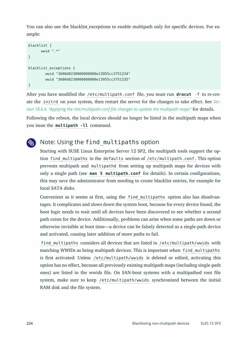
You can also use the blacklist_exceptions to enable multipath only for specific devices. For ex-ample:
blacklist { wwid ".*"}
blacklist_exceptions { wwid "3600d0230000000000e13955cc3751234" wwid "3600d0230000000000e13955cc3751235"}
After you have modified the /etc/multipath.conf le, you must run dracut -f to re-cre-ate the initrd on your system, then restart the server for the changes to take effect. See Sec-
tion 18.6.4, “Applying the /etc/multipath.conf file changes to update the multipath maps” for details.
Following the reboot, the local devices should no longer be listed in the multipath maps whenyou issue the multipath -ll command.
Note: Using the find_multipaths optionStarting with SUSE Linux Enterprise Server 12 SP2, the multipath tools support the op-tion find_multipaths in the defaults section of /etc/multipath.conf . This optionprevents multipath and multipathd from setting up multipath maps for devices withonly a single path (see man 5 multipath.conf for details). In certain configurations,this may save the administrator from needing to create blacklist entries, for example forlocal SATA disks.
Convenient as it seems at rst, using the find_multipaths option also has disadvan-tages. It complicates and slows down the system boot, because for every device found, theboot logic needs to wait until all devices have been discovered to see whether a secondpath exists for the device. Additionally, problems can arise when some paths are down orotherwise invisible at boot time—a device can be falsely detected as a single-path deviceand activated, causing later addition of more paths to fail.
find_multipaths considers all devices that are listed in /etc/multipath/wwids withmatching WWIDs as being multipath devices. This is important when find_multipathsis rst activated: Unless /etc/multipath/wwids is deleted or edited, activating thisoption has no effect, because all previously existing multipath maps (including single-pathones) are listed in the wwids le. On SAN-boot systems with a multipathed root lesystem, make sure to keep /etc/multipath/wwids synchronized between the initialRAM disk and the le system.
224 Blacklisting non-multipath devices SLES 15 SP3

In summary, using find_multipaths may be convenient in certain use cases, but SUSEstill recommends the default configuration with a properly configured blacklist and black-list exceptions.
18.9 Configuring user-friendly names or alias namesA multipath device can be identified by its WWID, by a user-friendly name, or by an alias thatyou assign for it. Device node names in the form of /dev/sdn and /dev/dm-n can change onreboot and might be assigned to different devices each time. A device’s WWID, user-friendlyname, and alias name persist across reboots, and are the preferred way to identify the device.
Important: Using persistent names is recommendedBecause device node names in the form of /dev/sdn and /dev/dm-n can change onreboot, referring to multipath devices by their WWID is preferred. You can also use auser-friendly name or alias that is mapped to the WWID to identify the device uniquelyacross reboots.
The following table describes the types of device names that can be used for a device in the /etc/multipath.conf le. For an example of multipath.conf settings, see the /usr/share/doc/packages/multipath-tools/multipath.conf.synthetic le.
TABLE 18.4: COMPARISON OF MULTIPATH DEVICE NAME TYPES
Name Types Description
WWID (de-fault)
The serial WWID (Worldwide Identifier) is an identifier for the multipathdevice that is guaranteed to be globally unique and unchanging. The de-fault name used in multipathing is the ID of the logical unit as found inthe /dev/disk/by-id directory. For example, a device with the WWID of3600508e0000000009e6baa6f609e7908 is listed as /dev/disk/by-id/scsi-3600508e0000000009e6baa6f609e7908 .
User-friendly The Device Mapper Multipath device names in the /dev/mapper directoryalso reference the ID of the logical unit. These multipath device names areuser-friendly names in the form of /dev/mapper/mpathN , such as /dev/
225 Configuring user-friendly names or alias names SLES 15 SP3

Name Types Description
mapper/mpath0 . The names are unique and persistent because they use the/var/lib/multipath/bindings le to track the association between theUUID and user-friendly names.
Alias An alias name is a globally unique name that the administrator providesfor a multipath device. Alias names override the WWID and the user-friendly /dev/mapper/mpathN names.
If you are using user_friendly_names, do not set the alias to mpath N for-mat. This may conflict with an automatically assigned user-friendly name,and give you incorrect device node names.
The global multipath user_friendly_names option in the /etc/multipath.conf le is usedto enable or disable the use of user-friendly names for multipath devices. If it is set to no (thedefault), multipath uses the WWID as the name of the device. If it is set to yes , multipath usesthe /var/lib/multipath/bindings le to assign a persistent and unique name to the devicein the form of mpath<N> in the /dev/mapper directory. The bindings file option in the /etc/multipath.conf le can be used to specify an alternate location for the bindings le.
The global multipath alias option in the /etc/multipath.conf le is used to explicitly assigna name to the device. If an alias name is set up for a multipath device, the alias is used insteadof the WWID or the user-friendly name.
Using the user_friendly_names option can be problematic in the following situations:
Root device is using multipath:
If the system root device is using multipath and you use the user_friendly_names option,the user-friendly settings in the /var/lib/multipath/bindings le are included in theinitrd . If you later change the storage setup, such as by adding or removing devices,there is a mismatch between the bindings setting inside the initrd and the bindingssettings in /var/lib/multipath/bindings .
Warning: Binding mismatchesA bindings mismatch between initrd and /var/lib/multipath/bindings canlead to a wrong assignment of mount points to devices, which can result in lesystem corruption and data loss.
226 Configuring user-friendly names or alias names SLES 15 SP3

To avoid this problem, we recommend that you use the default WWID settings for thesystem root device. You should not use aliases for the system root device. Because thedevice name would differ, using an alias causes you to lose the ability to seamlessly switcho multipathing via the kernel command line.
Mounting /var from another partition:
The default location of the user_friendly_names configuration le is /var/lib/mul-tipath/bindings . If the /var data is not located on the system root device but mountedfrom another partition, the bindings le is not available when setting up multipathing.Make sure that the /var/lib/multipath/bindings le is available on the system rootdevice and multipath can nd it. For example, this can be done as follows:
1. Move the /var/lib/multipath/bindings le to /etc/multipath/bindings .
2. Set the bindings_file option in the defaults section of / etc/multipath.confto this new location. For example:
defaults { user_friendly_names yes bindings_file "/etc/multipath/bindings"}
Multipath is in the initrd:
Even if the system root device is not on multipath, it is possible for multipath to be includedin the initrd . For example, this can happen if the system root device is on LVM. If youuse the user_friendly_names option and multipath is in the initrd , you should bootwith the parameter multipath=off to avoid problems.This disables multipath only in the initrd during system boots. After the system boots,the boot.multipath and multipathd boot scripts can activate multipathing.
Multipathing in HA clusters:
See Section 18.9.1, “Multipath device names in HA clusters” for details.
To enable user-friendly names or to specify aliases:
1. Open the /etc/multipath.conf le in a text editor with root privileges.
2. (Optional) Modify the location of the /var/lib/multipath/bindings le.The alternate path must be available on the system root device where multipath can nd it.
a. Move the /var/lib/multipath/bindings le to /etc/multipath/bindings .
227 Configuring user-friendly names or alias names SLES 15 SP3

b. Set the bindings_file option in the defaults section of / etc/multipath.confto this new location. For example:
defaults { user_friendly_names yes bindings_file "/etc/multipath/bindings"}
3. (Optional, not recommended) Enable user-friendly names:
a. Uncomment the defaults section and its ending bracket.
b. Uncomment the user_friendly_names option , then change its value from No toYes.For example:
## Use user-friendly names, instead of using WWIDs as names.defaults { user_friendly_names yes}
4. (Optional) Specify your own names for devices by using the alias option in the multi-path section.For example:
## Use alias names, instead of using WWIDs as names.multipaths { multipath { wwid 36006048000028350131253594d303030 alias blue1 } multipath { wwid 36006048000028350131253594d303041 alias blue2 } multipath { wwid 36006048000028350131253594d303145 alias yellow1 } multipath { wwid 36006048000028350131253594d303334 alias yellow2 }}
228 Configuring user-friendly names or alias names SLES 15 SP3

Important: WWID compared to WWNWhen you define device aliases in the /etc/multipath.conf le, ensure that youuse each device’s WWID (such as 3600508e0000000009e6baa6f609e7908 ) andnot its WWN, which replaces the rst character of a device ID with 0x , such as0x600508e0000000009e6baa6f609e7908 .
5. Save your changes, then close the le.
6. After you have modified the /etc/multipath.conf le, you must run dracut -f to re-create the initrd on your system, then restart the server for the changes to take effect.See Section 18.6.4, “Applying the /etc/multipath.conf file changes to update the multipath maps”
for details.
To use the entire LUN directly (for example, if you are using the SAN features to partitionyour storage), you can use the /dev/disk/by-id/xxx names for mkfs , /etc/fstab , yourapplication, and so on. Partitioned devices have _part<n> appended to the device name, suchas /dev/disk/by-id/xxx_part1 .
In the /dev/disk/by-id directory, the multipath-mapped devices are represented by the de-vice’s dm-uuid* name or alias name (if you assign an alias for it in the /etc/multipath.confle). The scsi- and wwn- device names represent physical paths to the devices.
18.9.1 Multipath device names in HA clusters
Make sure that multipath devices have the same name across all devices by doing the following:
Use UUID and alias names to ensure that multipath device names are consistent acrossall nodes in the cluster. Alias names must be unique across all nodes. Copy the /etc/multipath.conf le from the node to the /etc/ directory for all of the other nodes inthe cluster.
When using links to multipath-mapped devices, ensure that you specify the dm-uuid*name or alias name in the /dev/disk/by-id directory, and not a xed path instance ofthe device. For information, see Section 18.9, “Configuring user-friendly names or alias names”.
Set the user_friendly_names configuration option to no to disable it. A user-friendlyname is unique to a node, but a device might not be assigned the same user-friendly nameon every node in the cluster.
229 Multipath device names in HA clusters SLES 15 SP3

Note: User-friendly namesIf you really need to use user-friendly names, you can force the system-defined user-friendly names to be consistent across all nodes in the cluster by doing the following:
1. In the /etc/multipath.conf le on one node:
1. Set the user_friendly_names configuration option to yes to enable it.Multipath uses the /var/lib/multipath/bindings le to assign a persistentand unique name to the device in the form of mpath<N> in the /dev/mapperdirectory.
2. (Optional) Set the bindings_file option in the defaults section of the /etc/multipath.conf le to specify an alternate location for the bindingsle.The default location is /var/lib/multipath/bindings .
2. Set up all of the multipath devices on the node.
3. Copy the /etc/multipath.conf le from the node to the /etc/ directory of allthe other nodes in the cluster.
4. Copy the bindings le from the node to the bindings_file path on all of theother nodes in the cluster.
5. After you have modified the /etc/multipath.conf le, you must run dracut -f to re-create the initrd on your system, then restart the node for the changesto take effect. See Section 18.6.4, “Applying the /etc/multipath.conf file changes to update
the multipath maps” for details. This applies to all affected nodes.
18.10 Configuring path failover policies and prioritiesIn a Linux host, when there are multiple paths to a storage controller, each path appears as aseparate block device, and results in multiple block devices for single LUN. The Device MapperMultipath service detects multiple paths with the same LUN ID, and creates a new multipathdevice with that ID. For example, a host with two HBAs attached to a storage controller with
230 Configuring path failover policies and priorities SLES 15 SP3

two ports via a single unzoned Fibre Channel switch sees four block devices: /dev/sda , /dev/sdb , /dev/sdc , and /dev/sdd . The Device Mapper Multipath service creates a single blockdevice, /dev/mpath/mpath1 , that reroutes I/O through those four underlying block devices.
This section describes how to specify policies for failover and configure priorities for the paths.Note that after you have modified the /etc/multipath.conf le, you must run dracut -f tore-create the initrd on your system, then restart the server for the changes to take effect. SeeSection 18.6.4, “Applying the /etc/multipath.conf file changes to update the multipath maps” for details.
18.10.1 Configuring the path failover policies
Use the multipath command with the -p option to set the path failover policy:
> sudo multipath DEVICENAME -p POLICY
Replace POLICY with one of the following policy options:
TABLE 18.5: GROUP POLICY OPTIONS FOR THE MULTIPATH -P COMMAND
Policy Option Description
failover (Default) One path per priority group.
multibus All paths in one priority group.
group_by_serial One priority group per detected serial number.
group_by_prio One priority group per path priority value. Priorities are determinedby callout programs specified as a global, per-controller, or per-mul-tipath option in the /etc/multipath.conf configuration le.
group_by_n-ode_name
One priority group per target node name. Target node names arefetched in the /sys/class/fc_transport/target*/node_name lo-cation.
18.10.2 Configuring failover priorities
You must manually enter the failover priorities for the device in the /etc/multipath.conf le.Examples for all settings and options can be found in the /usr/share/doc/packages/multi-path-tools/multipath.conf.annotated le.
231 Configuring the path failover policies SLES 15 SP3

18.10.2.1 Understanding priority groups and attributes
A priority group is a collection of paths that go to the same physical LUN. By default, I/O is dis-tributed in a round-robin fashion across all paths in the group. The multipath command auto-matically creates priority groups for each LUN in the SAN based on the path_grouping_policysetting for that SAN. The multipath command multiplies the number of paths in a group by thegroup’s priority to determine which group is the primary. The group with the highest calculatedvalue is the primary. When all paths in the primary group are failed, the priority group withthe next highest value becomes active.
A path priority is an integer value assigned to a path. The higher the value, the higher the priority.An external program is used to assign priorities for each path. For a given device, the paths withthe same priorities belong to the same priority group.
The prio setting is used in the defaults{} or devices{} section of the /etc/multi-path.conf le. It is silently ignored when it is specified for an individual multipath definitionin the multipaths{) section. The prio line specifies the prioritizer. If the prioritizer requiresan argument, you specify the argument by using the prio_args keyword on a second line.
PRIO Settings for the Defaults or Devices Sections
prio
Specifies the prioritizer program to call to obtain a path priority value. Weights aresummed for each path group to determine the next path group to use in case of failure.Use the prio_args keyword to specify arguments if the specified prioritizer requires ar-guments.If no prio keyword is specified, all paths are equal. The default setting is const with aprio_args setting with no value.
prio "const"prio_args ""
Example prioritizer programs include:
Prioritizer Program Description
alua Generates path priorities based on the SCSI-3 ALUA settings.
const Generates the same priority for all paths.
232 Configuring failover priorities SLES 15 SP3

Prioritizer Program Description
emc Generates the path priority for EMC arrays.
hdc Generates the path priority for Hitachi HDS Modular storagearrays.
hp_sw Generates the path priority for Compaq/HP controller in ac-tive/standby mode.
ontap Generates the path priority for NetApp arrays.
random Generates a random priority for each path.
rdac Generates the path priority for LSI/Engenio RDAC controller.
weightedpath Generates the path priority based on the weighted valuesyou specify in the arguments for prio_args .
path_latency Generates the path priority based on a latency algorithm,which is configured with the prio_args keyword.
prio_args arguments
These are the arguments for the prioritizer programs that require arguments. Most prio pro-grams do not need arguments. There is no default. The values depend on the prio setting andwhether the prioritizer requires any of the following arguments:
weighted
Requires a value of the form [hbtl|devname|serial|wwn] REGEX1 PRIO1 REGEX2PRIO2 ...Regex must be of SCSI H:B:T:L format, for example 1:0:.:. and *:0:0:., with a weight value,where H, B, T, L are the host, bus, target, and LUN IDs for a device. For example:
prio "weightedpath"prio_args "hbtl 1:.:.:. 2 4:.:.:. 4"
devname
Regex is in device name format. For example: sda, sd.e
serial
233 Configuring failover priorities SLES 15 SP3

Regex is in serial number format. For example: .*J1FR.*324. Look up your serial numberwith the multipathd show paths format %z command. ( multipathd show wildcardsdisplays all format wildcards.)
alua
If exclusive_pref_bit is set for a device ( alua exclusive_pref_bit ), paths with thepreferred path bit set will always be in their own path group.
path_latency
path_latency adjusts latencies between remote and local storage arrays if both arraysuse the same type of hardware. Usually the latency on the remote array will be higher, soyou can tune the latency to bring them closer together. This requires a value pair of theform io_num=20 base_num=10 .io_num is the number of read IOs sent to the current path continuously, which are usedto calculate the average path latency. Valid values are integers from 2 to 200.base_num is the logarithmic base number, used to partition different priority ranks. Validvalues are integers from 2 to 10. The maximum average latency value is 100s, the minimumis 1 μs. For example, if base_num=10 , the paths will be grouped in priority groups withpath latency <=1 μs, (1 μs, 10 μs], (10 μs, 100 μs), (100 μs, 1 ms), (1 ms, 10 ms), (10 ms,100 ms), (100 ms, 1 s), (1 s, 10 s), (10 s, 100 s), >100 s.
Multipath Attributes
Multipath attributes are used to control the behavior of multipath I/O for devices. You canspecify attributes as defaults for all multipath devices. You can also specify attributes that applyonly to a given multipath device by creating an entry for that device in the multipaths sectionof the multipath configuration le.
user_friendly_names
Specifies whether to use world-wide IDs (WWIDs) or to use the /var/lib/multi-
path/bindings le to assign a persistent and unique alias to the multipath devices in theform of /dev/mapper/mpathN .This option can be used in the devices section and the multipaths section.
Value Description
no (Default) Use the WWIDs shown in the /dev/disk/by-id/ lo-cation.
234 Configuring failover priorities SLES 15 SP3

Value Description
yes Autogenerate user-friendly names as aliases for the multipathdevices instead of the actual ID.
failback
Specifies whether to monitor the failed path recovery, and indicates the timing for groupfailback after failed paths return to service.When the failed path recovers, the path is added back into the multipath-enabled pathlist based on this setting. Multipath evaluates the priority groups, and changes the activepriority group when the priority of the primary path exceeds the secondary group.
Value Description
manual (Default) The failed path is not monitored for recovery. The ad-ministrator runs the multipath command to update enabledpaths and priority groups.
followover Only perform automatic failback when the rst path of a path-group becomes active. This keeps a node from automaticallyfailing back when another node requested the failover.
immediate When a path recovers, enable the path immediately.
N When the path recovers, wait N seconds before enabling thepath. Specify an integer value greater than 0.
We recommend failback setting of manual for multipath in cluster environments to pre-vent multipath failover ping-pong.
failback "manual"
Important: VerificationMake sure that you verify the failback setting with your storage system vendor.Different storage systems can require different settings.
no_path_retry
235 Configuring failover priorities SLES 15 SP3

Specifies the behaviors to use on path failure.
Value Description
N Specifies the number of retries until multipath stops thequeuing and fails the path. Specify an integer value greaterthan 0.
In a cluster, you can specify a value of “0” to prevent queuingand allow resources to fail over.
fail Specifies immediate failure (no queuing).
queue Never stop queuing (queue forever until the path comes alive).
We recommend a retry setting of fail or 0 in the /etc/multipath.conf le whenworking in a cluster. This causes the resources to fail over when the connection is lost tostorage. Otherwise, the messages queue and the resource failover cannot occur.
no_path_retry "fail"no_path_retry "0"
Important: VerificationMake sure that you verify the retry settings with your storage system vendor. Dif-ferent storage systems can require different settings.
path_checker
Determines the state of the path.
Value Description
directio Reads the rst sector that has direct I/O.This is useful for DASD devices. Logs fail-ure messages in the systemd journal (seeBook “Administration Guide”, Chapter 17
“journalctl: Query the systemd journal”).
236 Configuring failover priorities SLES 15 SP3

Value Description
tur Issues an SCSI test unit ready command tothe device. This is the preferred setting ifthe LUN supports it. On failure, the com-mand does not ll up the systemd logjournal with messages.
CUSTOM_VENDOR_VALUE Some SAN vendors provide custompath_checker options:
cciss_tur : Checks the path statefor HP Smart Storage Arrays.
emc_clariion : Queries the EMCClariion EVPD page 0xC0 to deter-mine the path state.
hp_sw : Checks the path state (Up,Down, or Ghost) for HP storage ar-rays with Active/Standby rmware.
rdac : Checks the path state forthe LSI/Engenio RDAC storage con-troller.
path_grouping_policy
Specifies the path grouping policy for a multipath device hosted by a given controller.
Value Description
failover (Default) One path is assigned per priority group so that onlyone path at a time is used.
multibus All valid paths are in one priority group. Traffic is load-bal-anced across all active paths in the group.
237 Configuring failover priorities SLES 15 SP3

Value Description
group_by_prio One priority group exists for each path priority value. Pathswith the same priority are in the same priority group. Prioritiesare assigned by an external program.
group_by_serial Paths are grouped by the SCSI target serial number (controllernode WWN).
group_by_n-
ode_name
One priority group is assigned per target node name. Targetnode names are fetched in /sys/class/fc_transport/tar-get*/node_name .
path_selector
Specifies the path-selector algorithm to use for load balancing.
Value Description
round-robin 0 The load-balancing algorithm used to balance traffic across allactive paths in a priority group.
queue-length 0 A dynamic load balancer that balances the number of in-ightI/O on paths similar to the least-pending option.
service-time 0 (Default) A service-time oriented load balancer that balances I/O on paths according to the latency.
pg_timeout
Specifies path group timeout handling. No value can be specified; an internal default is set.
polling_interval
Specifies the time in seconds between the end of one path checking cycle and the beginningof the next path checking cycle.Specify an integer value greater than 0. The default value is 5. Make sure that you verifythe polling_interval setting with your storage system vendor. Different storage systems canrequire different settings.
rr_min_io_rq
Specifies the number of I/O requests to route to a path before switching to the next pathin the current path group, using request-based device-mapper-multipath.
238 Configuring failover priorities SLES 15 SP3
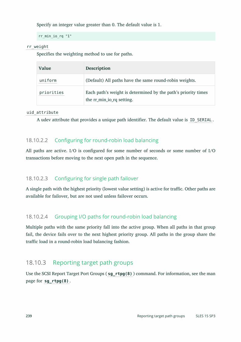
Specify an integer value greater than 0. The default value is 1.
rr_min_io_rq "1"
rr_weight
Specifies the weighting method to use for paths.
Value Description
uniform (Default) All paths have the same round-robin weights.
priorities Each path’s weight is determined by the path’s priority timesthe rr_min_io_rq setting.
uid_attribute
A udev attribute that provides a unique path identifier. The default value is ID_SERIAL .
18.10.2.2 Configuring for round-robin load balancing
All paths are active. I/O is configured for some number of seconds or some number of I/Otransactions before moving to the next open path in the sequence.
18.10.2.3 Configuring for single path failover
A single path with the highest priority (lowest value setting) is active for traffic. Other paths areavailable for failover, but are not used unless failover occurs.
18.10.2.4 Grouping I/O paths for round-robin load balancing
Multiple paths with the same priority fall into the active group. When all paths in that groupfail, the device fails over to the next highest priority group. All paths in the group share thetraffic load in a round-robin load balancing fashion.
18.10.3 Reporting target path groups
Use the SCSI Report Target Port Groups ( sg_rtpg(8) ) command. For information, see the manpage for sg_rtpg(8) .
239 Reporting target path groups SLES 15 SP3

18.11 Configuring multipath I/O for the root deviceDevice Mapper Multipath I/O (DM-MPIO) is available and supported for /boot and /root inSUSE Linux Enterprise Server. In addition, the YaST partitioner in the YaST installer supportsenabling multipath during the install.
18.11.1 Enabling multipath I/O at install time
To install the operating system on a multipath device, the multipath software must be running atinstall time. The multipathd daemon is not automatically active during the system installation.You can start it by using the Configure Multipath option in the YaST Partitioner.
18.11.1.1 Enabling multipath I/O at install time on an active/active multipathstorage LUN
1. Choose Expert Partitioner on the Suggested Partitioning screen during the installation.
2. Select the Hard Disks main icon, click the Configure button, then select Configure Multipath.
3. Start multipath.YaST starts to rescan the disks and shows available multipath devices (such as /dev/disk/by-id/dm-uuid-mpath-3600a0b80000f4593000012ae4ab0ae65 ). This is the device thatshould be used for all further processing.
4. Click Next to continue with the installation.
18.11.1.2 Enabling multipath I/O at install time on an active/passivemultipath storage LUN
The multipathd daemon is not automatically active during the system installation. You canstart it by using the Configure Multipath option in the YaST Partitioner.
To enable multipath I/O at install time for an active/passive multipath storage LUN:
1. Choose Expert Partitioner on the Suggested Partitioning screen during the installation.
2. Select the Hard Disks main icon, click the Configure button, then select Configure Multipath.
240 Configuring multipath I/O for the root device SLES 15 SP3

3. Start multipath.YaST starts to rescan the disks and shows available multipath devices (such as /dev/disk/by-id/dm-uuid-mpath-3600a0b80000f4593000012ae4ab0ae65 ). This is the device thatshould be used for all further processing. Write down the device path and UUID; you willneed it later.
4. Click Next to continue with the installation.
5. After all settings are done and the installation is finished, YaST starts to write the bootloader information, and displays a countdown to restart the system. Stop the counter byclicking the Stop button and press Ctrl – Alt – F5 to access a console.
6. Use the console to determine if a passive path was entered in the /boot/grub2/de-vice.map le for the hd0 entry.This is necessary because the installation does not distinguish between active and passivepaths.
a. Mount the root device to /mnt by entering
> sudo mount /dev/disk/by-id/UUID;_part2 /mnt
For example, enter
> sudo mount /dev/disk/by-id/dm-uuid-mpath-3600a0b80000f4593000012ae4ab0ae65_part2 /mnt
b. Mount the boot device to /mnt/boot by entering
> sudo mount /dev/disk/by-id/UUID_part1 /mnt/boot
For example, enter
> sudo mount /dev/disk/by-id/dm-uuid-mpath-3600a0b80000f4593000012ae4ab0ae65_part2 /mnt/boot
241 Enabling multipath I/O at install time SLES 15 SP3

c. In the /mnt/boot/grub2/device.map le, determine if the hd0 entry points to apassive path, then do one of the following:
Active path: No action is needed. Skip all remaining steps and return to theYaST graphical environment by pressing Ctrl – Alt – F7 and continue with theinstallation.
Passive path: The configuration must be changed and the boot loader mustbe reinstalled.
7. If the hd0 entry points to a passive path, change the configuration and reinstall the bootloader:
a. Enter the following commands at the console prompt:
mount -o bind /dev /mnt/dev mount -o bind /sys /mnt/sys mount -o bind /proc /mnt/proc chroot /mnt
b. At the console, run multipath -ll , then check the output to nd the active path.Passive paths are agged as ghost .
c. In the /boot/grub2/device.map le, change the hd0 entry to an active path, savethe changes, and close the le.
d. Reinstall the boot loader by entering
grub-install /dev/disk/by-id/UUID_part1 /mnt/boot
For example, enter
grub-install /dev/disk/by-id/dm-uuid-mpath-3600a0b80000f4593000012ae4ab0ae65_part2 /mnt/boot
e. Enter the following commands:
exitumount /mnt/*umount /mnt
8. Return to the YaST graphical environment by pressing Ctrl – Alt – F7 .
242 Enabling multipath I/O at install time SLES 15 SP3

9. Click OK to continue with the installation reboot.
18.11.2 Enabling multipath I/O for an existing root device
1. Install Linux with only a single path active, preferably one where the by-id symboliclinks are listed in the partitioner.
2. Mount the devices by using the /dev/disk/by-id path used during the install.
3. Open or create /etc/dracut.conf.d/10-mp.conf and add the following line (mind theleading whitespace):
force_drivers+=" dm-multipath"
4. For IBM Z, before running dracut , edit the /etc/zipl.conf le to change the by-pathinformation in zipl.conf with the same by-id information that was used in /etc/fstab .
5. Run dracut -f to update the initrd image.
6. For IBM Z, after running dracut , run zipl .
7. Reboot the server.
18.11.3 Disabling multipath I/O on the root device
Add multipath=off to the kernel command line. This can be done with the YaST Boot Loadermodule. Open Boot Loader Installation Kernel Parameters and add the parameter to both com-mand lines.
This affects only the root device. All other devices are not affected.
18.12 Configuring multipath I/O for an existingsoftware RAIDIdeally, you should configure multipathing for devices before you use them as components ofa software RAID device. If you add multipathing after creating any software RAID devices,the DM-MPIO service might be starting after the multipath service on reboot, which makesmultipathing appear not to be available for RAIDs. You can use the procedure in this section toget multipathing running for a previously existing software RAID.
243 Enabling multipath I/O for an existing root device SLES 15 SP3
For example, you might need to configure multipathing for devices in a software RAID underthe following circumstances:
If you create a new software RAID as part of the Partitioning settings during a new installor upgrade.
If you did not configure the devices for multipathing before using them in the softwareRAID as a member device or spare.
If you grow your system by adding new HBA adapters to the server or expanding thestorage subsystem in your SAN.
Note: AssumptionsThe following instructions assume the software RAID device is /dev/mapper/mpath0 ,which is its device name as recognized by the kernel. It assumes you have enabled user-friendly names in the /etc/multipath.conf le as described in Section 18.9, “Configuring
user-friendly names or alias names”.
Make sure to modify the instructions for the device name of your software RAID.
1. Open a terminal console.Except where otherwise directed, use this console to enter the commands in the followingsteps.
2. If any software RAID devices are currently mounted or running, enter the following com-mands for each device to unmount the device and stop it.
> sudo umount /dev/mapper/mpath0> sudo mdadm --misc --stop /dev/mapper/mpath0
3. Stop the md service by entering
> sudo systemctl stop mdmonitor
4. Start the multipathd daemon by entering the following command:
> systemctl start multipathd
244 Configuring multipath I/O for an existing software RAID SLES 15 SP3

5. After the multipathing service has been started, verify that the software RAID’s componentdevices are listed in the /dev/disk/by-id directory. Do one of the following:
Devices are listed: The device names should now have symbolic links to their DeviceMapper Multipath device names, such as /dev/dm-1 .
Devices are not listed: Force the multipath service to recognize them by flushingand rediscovering the devices by entering
> sudo multipath -F> sudo multipath -v0
The devices should now be listed in /dev/disk/by-id , and have symbolic links totheir Device Mapper Multipath device names. For example:
lrwxrwxrwx 1 root root 10 2011-01-06 11:42 dm-uuid-mpath-36006016088d014007e0d0d2213ecdf11 -> ../../dm-1
6. Restart the mdmonitor service and the RAID device by entering
> sudo systemctl start mdmonitor
7. Check the status of the software RAID by entering
> sudo mdadm --detail /dev/mapper/mpath0
The RAID’s component devices should match their Device Mapper Multipath device namesthat are listed as the symbolic links of devices in the /dev/disk/by-id directory.
8. In case the root ( / ) device or any parts of it (such as /var , /etc , /log ) are on the SANand multipath is needed to boot, rebuild the initrd :
> dracut -f --add-multipath
9. Reboot the server to apply the changes.
10. Verify that the software RAID array comes up properly on top of the multipathed devicesby checking the RAID status. Enter
> sudo mdadm --detail /dev/mapper/mpath0
For example:
Number Major Minor RaidDevice State
245 Configuring multipath I/O for an existing software RAID SLES 15 SP3

0 253 0 0 active sync /dev/dm-0
1 253 1 1 active sync /dev/dm-1
2 253 2 2 active sync /dev/dm-2
Note: Using mdadm with multipath devicesThe mdadm tool requires that the devices be accessed by the ID rather than by the devicenode path. Refer to Section 18.4.3, “Using MDADM for multipathed devices” for details.
18.13 Using LVM2 on multipath devicesWhen using multipath, all paths to a resource are present as devices in the device tree. By defaultLVM checks if there is a multipath device on top of any device in the device tree. If LVM ndsa multipath device on top, it assumes that the device is a multipath component and ignores the(underlying) device. This is the most likely desired behavior, but it can be changed in /etc/lvm/lvm.conf . When multipath_component_detection is set to 0, LVM is scanning multipathcomponent devices. The default entry in lvm.conf is:
# By default, LVM2 will ignore devices used as component paths # of device-mapper multipath devices. # 1 enables; 0 disables. multipath_component_detection = 1
18.14 Best practice
18.14.1 Scanning for new devices without rebooting
If your system has already been configured for multipathing and you later need to add storage tothe SAN, you can use the rescan-scsi-bus.sh script to scan for the new devices. By default,this script scans all HBAs with typical LUN ranges. The general syntax for the command lookslike the following:
> sudo rescan-scsi-bus.sh [options] [host [host ...]]
246 Using LVM2 on multipath devices SLES 15 SP3

For most storage subsystems, the script can be run successfully without options. However, somespecial cases might need to use one or more options. Run rescan-scsi-bus.sh --help fordetails.
Warning: EMC PowerPath environmentsIn EMC PowerPath environments, do not use the rescan-scsi-bus.sh utility providedwith the operating system or the HBA vendor scripts for scanning the SCSI buses. To avoidpotential le system corruption, EMC requires that you follow the procedure provided inthe vendor documentation for EMC PowerPath for Linux.
Use the following procedure to scan the devices and make them available to multipathing with-out rebooting the system.
1. On the storage subsystem, use the vendor’s tools to allocate the device and update itsaccess control settings to allow the Linux system access to the new storage. Refer to thevendor’s documentation for details.
2. Scan all targets for a host to make its new device known to the middle layer of the Linuxkernel’s SCSI subsystem. At a terminal console prompt, enter
> sudo rescan-scsi-bus.sh
Depending on your setup, you might need to run rescan-scsi-bus.sh with optionalparameters. Refer to rescan-scsi-bus.sh --help for details.
3. Check for scanning progress in the systemd journal (see Book “Administration Guide”, Chap-
ter 17 “journalctl: Query the systemd journal” for details). At a terminal console prompt,enter
> sudo journalctl -r
This command displays the last lines of the log. For example:
> sudo journalctl -rFeb 14 01:03 kernel: SCSI device sde: 81920000Feb 14 01:03 kernel: SCSI device sdf: 81920000Feb 14 01:03 multipathd: sde: path checker registeredFeb 14 01:03 multipathd: sdf: path checker registeredFeb 14 01:03 multipathd: mpath4: event checker startedFeb 14 01:03 multipathd: mpath5: event checker started
247 Scanning for new devices without rebooting SLES 15 SP3

Feb 14 01:03:multipathd: mpath4: remaining active paths: 1Feb 14 01:03 multipathd: mpath5: remaining active paths: 1[...]
4. Repeat the previous steps to add paths through other HBA adapters on the Linux systemthat are connected to the new device.
5. Run the multipath command to recognize the devices for DM-MPIO configuration. Ata terminal console prompt, enter
> sudo multipath
You can now configure the new device for multipathing.
18.14.2 Scanning for new partitioned devices without rebooting
Use the example in this section to detect a newly added multipathed LUN without rebooting.
Warning: EMC PowerPath environmentsIn EMC PowerPath environments, do not use the rescan-scsi-bus.sh utility providedwith the operating system or the HBA vendor scripts for scanning the SCSI buses. To avoidpotential le system corruption, EMC requires that you follow the procedure provided inthe vendor documentation for EMC PowerPath for Linux.
1. Open a terminal console.
2. Scan all targets for a host to make its new device known to the middle layer of the Linuxkernel’s SCSI subsystem. At a terminal console prompt, enter
> rescan-scsi-bus.sh
Depending on your setup, you might need to run rescan-scsi-bus.sh with optionalparameters. Refer to rescan-scsi-bus.sh --help for details.
3. Verify that the device is seen (such as if the link has a new time stamp) by entering
> ls -lrt /dev/dm-*
You can also verify the devices in /dev/disk/by-id by entering
248 Scanning for new partitioned devices without rebooting SLES 15 SP3

> ls -l /dev/disk/by-id/
4. Verify the new device appears in the log by entering
> sudo journalctl -r
5. Use a text editor to add a new alias definition for the device in the /etc/multipath.confle, such as data_vol3 .For example, if the UUID is 36006016088d014006e98a7a94a85db11 , make the followingchanges:
defaults { user_friendly_names yes }multipaths { multipath { wwid 36006016088d014006e98a7a94a85db11 alias data_vol3 } }
6. Create a partition table for the device by entering
> fdisk /dev/disk/by-id/dm-uuid-mpath-<UUID>
Replace UUID with the device WWID, such as 36006016088d014006e98a7a94a85db11 .
7. Trigger udev by entering
> sudo echo 'add' > /sys/block/DM_DEVICE/uevent
For example, to generate the device-mapper devices for the partitions on dm-8 , enter
> sudo echo 'add' > /sys/block/dm-8/uevent
8. Create a le system on the device /dev/disk/by-id/dm-uuid-mpath-UUID_partN . De-pending on your choice for the le system, you may use one of the following commands forthis purpose: mkfs.btrfs mkfs.ext3 , mkfs.ext4 , or mkfs.xfs . Refer to the respectiveman pages for details. Replace UUID_partN with the actual UUID and partition number,such as 36006016088d014006e98a7a94a85db11_part1.
9. Create a label for the new partition by entering the following command:
> sudo tune2fs -L LABELNAME /dev/disk/by-id/dm-uuid-UUID_partN
249 Scanning for new partitioned devices without rebooting SLES 15 SP3

Replace UUID_partN with the actual UUID and partition number, such as36006016088d014006e98a7a94a85db11_part1. Replace LABELNAME with a label of yourchoice.
10. Reconfigure DM-MPIO to let it read the aliases by entering
> sudo multipathd -k'reconfigure'
11. Verify that the device is recognized by multipathd by entering
> sudo multipath -ll
12. Use a text editor to add a mount entry in the /etc/fstab le.At this point, the alias you created in a previous step is not yet in the /dev/disk/by-label directory. Add a mount entry for the /dev/dm-9 path, then change the entry beforethe next time you reboot to
LABEL=LABELNAME
13. Create a directory to use as the mount point, then mount the device.
18.14.3 Viewing multipath I/O status
Querying the multipath I/O status outputs the current status of the multipath maps.
The multipath -l option displays the current path status as of the last time that the pathchecker was run. It does not run the path checker.
The multipath -ll option runs the path checker, updates the path information, then displaysthe current status information. This command always displays the latest information about thepath status.
> sudo multipath -ll3600601607cf30e00184589a37a31d911[size=127 GB][features="0"][hwhandler="1 emc"]
\_ round-robin 0 [active][first] \_ 1:0:1:2 sdav 66:240 [ready ][active] \_ 0:0:1:2 sdr 65:16 [ready ][active]
\_ round-robin 0 [enabled] \_ 1:0:0:2 sdag 66:0 [ready ][active] \_ 0:0:0:2 sdc 8:32 [ready ][active]
250 Viewing multipath I/O status SLES 15 SP3

For each device, it shows the device’s ID, size, features, and hardware handlers.
Paths to the device are automatically grouped into priority groups on device discovery. Only onepriority group is active at a time. For an active/active configuration, all paths are in the samegroup. For an active/passive configuration, the passive paths are placed in separate prioritygroups.
The following information is displayed for each group:
Scheduling policy used to balance I/O within the group, such as round-robin
Whether the group is active, disabled, or enabled
Whether the group is the rst (highest priority) group
Paths contained within the group
The following information is displayed for each path:
The physical address as HOST:BUS:TARGET:LUN , such as 1:0:1:2
Device node name, such as sda
Major:minor numbers
Status of the device
Note: Using iostat in multipath setupsIn multipath environments, the iostat command might lead to unexpected results. Bydefault, iostat filters out all block devices with no I/O. To make iostat show alldevices, use:
iostat -p ALL
18.14.4 Managing I/O in error situations
You might need to configure multipathing to queue I/O if all paths fail concurrently by enablingqueue_if_no_path. Otherwise, I/O fails immediately if all paths are gone. In certain scenarios,where the driver, the HBA, or the fabric experience spurious errors, DM-MPIO should be con-figured to queue all I/O where those errors lead to a loss of all paths, and never propagateerrors upward.
251 Managing I/O in error situations SLES 15 SP3

When you use multipathed devices in a cluster, you might choose to disable queue_if_no_path.This automatically fails the path instead of queuing the I/O, and escalates the I/O error to causea failover of the cluster resources.
Because enabling queue_if_no_path leads to I/O being queued indefinitely unless a path is rein-stated, ensure that multipathd is running and works for your scenario. Otherwise, I/O mightbe stalled indefinitely on the affected multipathed device until reboot or until you manuallyreturn to failover instead of queuing.
To test the scenario:
1. Open a terminal console.
2. Activate queuing instead of failover for the device I/O by entering
> sudo dmsetup message DEVICE_ID 0 queue_if_no_path
Replace the DEVICE_ID with the ID for your device. The 0 value represents the sector andis used when sector information is not needed.For example, enter:
> sudo dmsetup message 3600601607cf30e00184589a37a31d911 0 queue_if_no_path
3. Return to failover for the device I/O by entering
> sudo dmsetup message DEVICE_ID 0 fail_if_no_path
This command immediately causes all queued I/O to fail.Replace the DEVICE_ID with the ID for your device. For example, enter
> sudo dmsetup message 3600601607cf30e00184589a37a31d911 0 fail_if_no_path
To set up queuing I/O for scenarios where all paths fail:
1. Open a terminal console.
2. Open the /etc/multipath.conf le in a text editor.
3. Uncomment the defaults section and its ending bracket, then add the default_featuressetting, as follows:
defaults { default_features "1 queue_if_no_path"}
252 Managing I/O in error situations SLES 15 SP3

4. After you modify the /etc/multipath.conf le, you must run dracut -f to re-createthe initrd on your system, then reboot for the changes to take effect.
5. When you are ready to return to failover for the device I/O, enter
> sudo dmsetup message MAPNAME 0 fail_if_no_path
Replace the MAPNAME with the mapped alias name or the device ID for the device. The 0value represents the sector and is used when sector information is not needed.This command immediately causes all queued I/O to fail and propagates the error to thecalling application.
18.14.5 Resolving stalled I/O
If all paths fail concurrently and I/O is queued and stalled, do the following:
1. Enter the following command at a terminal console prompt:
> sudo dmsetup message MAPNAME 0 fail_if_no_path
Replace MAPNAME with the correct device ID or mapped alias name for the device. The 0value represents the sector and is used when sector information is not needed.This command immediately causes all queued I/O to fail and propagates the error to thecalling application.
2. Reactivate queuing by entering the following command:
> sudo dmsetup message MAPNAME 0 queue_if_no_path
18.14.6 Configuring default settings for IBM Z devices
Testing of the IBM Z device with multipathing has shown that the dev_loss_tmo parametershould be set to infinity (2147483647), and the fast_io_fail_tmo parameter should be setto 5 seconds. If you are using IBM Z devices, modify the /etc/multipath.conf le to specifythe values as follows:
defaults { dev_loss_tmo 2147483647 fast_io_fail_tmo 5
253 Resolving stalled I/O SLES 15 SP3

}
The dev_loss_tmo parameter sets the number of seconds to wait before marking a multipathlink as bad. When the path fails, any current I/O on that failed path fails. The default valuevaries according to the device driver being used. To use the driver’s internal timeouts, set thevalue to zero (0). It can also be set to "infinity" or 2147483647, which sets it to the max valueof 2147483647 seconds (68 years).
The fast_io_fail_tmo parameter sets the length of time to wait before failing I/O when alink problem is detected. I/O that reaches the driver fails. If I/O is in a blocked queue, the I/Odoes not fail until the dev_loss_tmo time elapses and the queue is unblocked.
If you modify the /etc/multipath.conf le, the changes are not applied until you updatethe multipath maps, or until the multipathd daemon is restarted ( systemctl restart mul-tipathd ).
18.14.7 Using multipath with NetApp devices
When using multipath for NetApp devices, we recommend the following settings in the /etc/multipath.conf le:
Set the default values for the following parameters globally for NetApp devices:
max_fds maxqueue_without_daemon no
Set the default values for the following parameters for NetApp devices in the hardwaretable:
dev_loss_tmo infinityfast_io_fail_tmo 5features "3 queue_if_no_path pg_init_retries 50"
18.14.8 Using --noflush with multipath devices
The --noflush option should always be used when running on multipath devices.
For example, in scripts where you perform a table reload, you use the --noflush option onresume to ensure that any outstanding I/O is not ushed, because you need the multipath topol-ogy information.
254 Using multipath with NetApp devices SLES 15 SP3

loadresume --noflush
18.14.9 SAN timeout settings when the root device is multipathed
A system with root ( / ) on a multipath device might stall when all paths have failed and areremoved from the system because a dev_loss_tmo timeout is received from the storage sub-system (such as Fibre Channel storage arrays).
If the system device is configured with multiple paths and the multipath no_path_retry set-ting is active, you should modify the storage subsystem’s dev_loss_tmo setting accordingly toensure that no devices are removed during an all-paths-down scenario. We strongly recommendthat you set the dev_loss_tmo value to be equal to or higher than the no_path_retry settingfrom multipath.
The recommended setting for the storage subsystem’s dev_los_tmo is
<dev_loss_tmo> = <no_path_retry> * <polling_interval>
where the following definitions apply for the multipath values:
no_path_retry is the number of retries for multipath I/O until the path is considered tobe lost, and queuing of IO is stopped.
polling_interval is the time in seconds between path checks.
Each of these multipath values should be set from the /etc/multipath.conf configurationle. For information, see Section 18.6, “Creating or modifying the /etc/multipath.conf file”.
18.15 Troubleshooting MPIOThis section describes some known issues and possible solutions for MPIO.
18.15.1 Installing GRUB2 on multipath devices
On legacy BIOS systems with Btrfs, grub2-install can fail with a permission denied. To x this,make sure that the /boot/grub2/SUBDIR/ subvolume is mounted in read-write (rw) mode.SUBDIR can be x86_64-efi or i386-pc .
255 SAN timeout settings when the root device is multipathed SLES 15 SP3

18.15.2 The system exits to emergency shell at boot whenmultipath is enabled
During boot the system exits into the emergency shell with messages similar to the following:
[ OK ] Listening on multipathd control socket. Starting Device-Mapper Multipath Device Controller...[ OK ] Listening on Device-mapper event daemon FIFOs. Starting Device-mapper event daemon... Expecting device dev-disk-by\x2duuid-34be48b2\x2dc21...32dd9.device... Expecting device dev-sda2.device...[ OK ] Listening on udev Kernel Socket.[ OK ] Listening on udev Control Socket. Starting udev Coldplug all Devices... Expecting device dev-disk-by\x2duuid-1172afe0\x2d63c...5d0a7.device... Expecting device dev-disk-by\x2duuid-c4a3d1de\x2d4dc...ef77d.device...[ OK ] Started Create list of required static device nodes ...current kernel. Starting Create static device nodes in /dev...[ OK ] Started Collect Read-Ahead Data.[ OK ] Started Device-mapper event daemon.[ OK ] Started udev Coldplug all Devices. Starting udev Wait for Complete Device Initialization...[ OK ] Started Replay Read-Ahead Data. Starting Load Kernel Modules... Starting Remount Root and Kernel File Systems...[ OK ] Started Create static devices[* ] (1 of 4) A start job is running for dev-disk-by\x2du...(7s / 1min 30s)[* ] (1 of 4) A start job is running for dev-disk-by\x2du...(7s / 1min 30s)
...
Timed out waiting for device dev-disk-by\x2duuid-c4a...cfef77d.device.[DEPEND] Dependency failed for /opt.[DEPEND] Dependency failed for Local File Systems.[DEPEND] Dependency failed for Postfix Mail Transport Agent.Welcome to emergency shellGive root password for maintenance(or press Control-D to continue):
At this stage, you are working in a temporary dracut emergency shell from the initrd environ-ment. To make the configuration changes described below persistent, you need to perform themin the environment of the installed system.
1. Identify what the system root ( / ) le system is. Inspect the content of /proc/cmdlineand look for the root= parameter.
256 The system exits to emergency shell at boot when multipath is enabled SLES 15 SP3

2. Verify whether the root le system is mounted:
> sudo systemctl status sysroot.mount
Tipdracut mounts the root le system under /sysroot by default.
From now on, let us assume that the root le system is mounted under /sysroot .
3. Mount system-required le systems under /sysroot , chroot into it, then mount all lesystems. For example:
> sudo for x in proc sys dev run; do mount --bind /$x /sysroot/$x; done> sudo chroot /sysroot /bin/bash> sudo mount -a
Refer to Book “Administration Guide”, Chapter 41 “Common problems and their solutions”, Sec-
tion 41.5.2.3 “Accessing the installed system” for more details.
4. Make changes to the multipath or dracut configuration as suggested in the proceduresbelow. Remember to rebuild initrd to include the modifications.
5. Exit the chroot environment by entering the exit command, then exit the emergencyshell and reboot the server by pressing Ctrl – D .
PROCEDURE 18.1: EMERGENCY SHELL: BLACKLIST FILE SYSTEMS
This x is required if the root le system is not on multipath but multipath is enabled. Insuch a setup, multipath tries to set its paths for all devices that are not blacklisted. Sincethe device with the root le system is already mounted, it is inaccessible for multipathand causes it to fail. Fix this issue by configuring multipath correctly by blacklisting theroot device in /etc/multipath.conf :
1. Run multipath -v2 in the emergency shell and identify the device for the root le system.It will result in an output similar to:
# multipath -v2Dec 18 10:10:03 | 3600508b1001030343841423043300400: ignoring map
The string between | and : is the WWID needed for blacklisting.
257 The system exits to emergency shell at boot when multipath is enabled SLES 15 SP3

2. Open /etc/multipath.conf and add the following:
blacklist { wwid "WWID"}
Replace WWID with the ID you retrieved in the previous step. For more information seeSection 18.8, “Blacklisting non-multipath devices”.
3. Rebuild the initrd using the following command:
> dracut -f --add-multipath
PROCEDURE 18.2: EMERGENCY SHELL: REBUILD THE initrd
This x is required if the multipath status (enabled or disabled) differs between initrdand system. To x this, rebuild the initrd :
If multipath has been enabled in the system, rebuild the initrd with multipath support withthis command:
> dracut --force --add multipath
In case Multipath has been disabled in the system, rebuild the initrd with Multipath supportwith this command:
> dracut --force -o multipath
PROCEDURE 18.3: EMERGENCY SHELL: REBUILD THE initrd
This x is required if the initrd does not contain drivers to access network attached storage.This may, for example, be the case when the system was installed without multipath orwhen the respective hardware was added or replaced.
1. Add the required driver(s) to the variable force_drivers in the le /etc/dracut.con-f.d/01-dist.conf . For example, if your system contains a RAID controller accessed bythe hpsa driver and multipathed devices connected to a QLogic controller accessed bythe driver qla23xx, this entry would look like:
force_drivers+="hpsa qla23xx"
2. Rebuild the initrd using the following command:
> dracut -f --add-multipath
258 The system exits to emergency shell at boot when multipath is enabled SLES 15 SP3

3. To prevent the system from booting into emergency mode if attaching the network storagefails, it is recommended to add the mount option _netdev to the respective entries in/etc/fstab .
18.15.3 PRIO settings for individual devices fail after upgrading tomultipath 0.4.9 or later
Multipath Tools from version 0.4.9 onward uses the prio setting in the defaults{} or de-vices{} section of the /etc/multipath.conf le. It silently ignores the keyword prio whenit is specified for an individual multipath definition in the multipaths{) section.
Multipath Tools 0.4.8 allowed the prio setting in the individual multipath definition in themultipaths{) section to override the prio settings in the defaults{} or devices{} section.
18.15.4 PRIO settings with arguments fail after upgrading tomultipath-tools-0.4.9 or later
When you upgrade from multipath-tools-0.4.8 to multipath-tools-0.4.9 , the prio set-tings in the /etc/multipath.conf le are broken for prioritizers that require an argument. Inmultipath-tools-0.4.9, the prio keyword is used to specify the prioritizer, and the prio_argskeyword is used to specify the argument for prioritizers that require an argument. Previously,both the prioritizer and its argument were specified on the same prio line.
For example, in multipath-tools-0.4.8, the following line was used to specify a prioritizer andits arguments on the same line.
prio "weightedpath hbtl [1,3]:.:.+:.+ 260 [0,2]:.:.+:.+ 20"
After upgrading to multipath-tools-0.4.9 or later, the command causes an error. The messageis similar to the following:
<Month day hh:mm:ss> | Prioritizer 'weightedpath hbtl [1,3]:.:.+:.+ 260[0,2]:.:.+:.+ 20' not found in /lib64/multipath
To resolve this problem, use a text editor to modify the prio line in the /etc/multipath.confle. Create two lines with the prioritizer specified on the prio line, and the prioritizer argumentspecified on the prio_args line below it:
prio "weightedpath"
259
PRIO settings for individual devices fail after upgrading to multipath 0.4.9 or later SLES 15
SP3

prio_args "hbtl [1,3]:.:.+:.+ 260 [0,2]:.:.+:.+ 20"
Restart the multipathd daemon for the changes to become active by running sudo systemctlrestart multipathd .
18.15.5 Technical information documents
For information about troubleshooting multipath I/O issues on SUSE Linux Enterprise Server,see the following Technical Information Documents (TIDs) in the SUSE Knowledgebase:
Using LVM on local and SAN attached devices (https://www.suse.com/support/kb/doc.php?
id=3617600)
Using LVM on Multipath (DM MPIO) Devices (https://www.suse.com/support/kb/doc.php?
id=7007498)
HOWTO: Add, Resize and Remove LUN without restarting SLES (https://www.suse.com/support/kb/
doc.php?id=7009660)
260 Technical information documents SLES 15 SP3

19 Sharing file systems with NFS
The Network File System (NFS) is a protocol that allows access to les on a server ina manner similar to accessing local les.
SUSE Linux Enterprise Server installs NFS v4.2, which introduces support for sparseles, le pre-allocation, server-side clone and copy, application data block (ADB),and labeled NFS for mandatory access control (MAC) (requires MAC on both clientand server).
19.1 OverviewThe Network File System (NFS) is a standardized, well-proven, and widely-supported networkprotocol that allows les to be shared between separate hosts.
The Network Information Service (NIS) can be used to have centralized user management in thenetwork. Combining NFS and NIS allows using le and directory permissions for access controlin the network. NFS with NIS makes a network transparent to the user.
In the default configuration, NFS completely trusts the network and thus any machine that isconnected to a trusted network. Any user with administrator privileges on any computer withphysical access to any network the NFS server trusts can access any les that the server makesavailable.
Often, this level of security is perfectly satisfactory, such as when the network that is trusted istruly private, often localized to a single cabinet or machine room, and no unauthorized accessis possible. In other cases, the need to trust a whole subnet as a unit is restrictive, and there is aneed for more ne-grained trust. To meet the need in these cases, NFS supports various securitylevels using the Kerberos infrastructure. Kerberos requires NFSv4, which is used by default. Fordetails, see Book “Security and Hardening Guide”, Chapter 7 “Network authentication with Kerberos”.
The following are terms used in the YaST module.
Exports
A directory exported by an NFS server, which clients can integrate into their systems.
NFS client
261 Overview SLES 15 SP3

The NFS client is a system that uses NFS services from an NFS server over the Network FileSystem protocol. The TCP/IP protocol is already integrated into the Linux kernel; there isno need to install any additional software.
NFS server
The NFS server provides NFS services to clients. A running server depends on the followingdaemons: nfsd (worker), idmapd (ID-to-name mapping for NFSv4, needed for certainscenarios only), statd (le locking), and mountd (mount requests).
NFSv3
NFSv3 is the version 3 implementation, the “old” stateless NFS that supports client au-thentication.
NFSv4
NFSv4 is the new version 4 implementation that supports secure user authentication viaKerberos. NFSv4 requires one single port only and thus is better suited for environmentsbehind a firewall than NFSv3.The protocol is specified as http://tools.ietf.org/html/rfc3530 .
pNFS
Parallel NFS, a protocol extension of NFSv4. Any pNFS clients can directly access the dataon an NFS server.
Important: Need for DNSIn principle, all exports can be made using IP addresses only. To avoid timeouts, youneed a working DNS system. DNS is necessary at least for logging purposes, because themountd daemon does reverse lookups.
19.2 Installing NFS serverThe NFS server is not part of the default installation. To install the NFS server using YaST, chooseSoftware Software Management, select Patterns, and enable the File Server option in the ServerFunctions section. Click Accept to install the required packages.
Like NIS, NFS is a client/server system. However, a machine can be both—it can supply lesystems over the network (export) and mount le systems from other hosts (import).
262 Installing NFS server SLES 15 SP3

Note: Mounting NFS volumes locally on the exporting serverMounting NFS volumes locally on the exporting server is not supported on SUSE LinuxEnterprise Server.
19.3 Configuring NFS serverConfiguring an NFS server can be done either through YaST or manually. For authentication,NFS can also be combined with Kerberos.
19.3.1 Exporting file systems with YaST
With YaST, turn a host in your network into an NFS server—a server that exports directoriesand les to all hosts granted access to it or to all members of a group. Thus, the server can alsoprovide applications without installing the applications locally on every host.
To set up such a server, proceed as follows:
PROCEDURE 19.1: SETTING UP AN NFS SERVER
1. Start YaST and select Network Services NFS Server; see Figure 19.1, “NFS server configuration
tool”. You may be prompted to install additional software.
263 Configuring NFS server SLES 15 SP3

FIGURE 19.1: NFS SERVER CONFIGURATION TOOL
2. Click the Start radio button.
3. If firewalld is active on your system, configure it separately for NFS (see Book “Security
and Hardening Guide”, Chapter 24 “Masquerading and firewalls”, Section 24.4 “firewalld”).YaST does not yet have complete support for firewalld , so ignore the "Firewall notconfigurable" message and continue.
4. Check whether you want to Enable NFSv4. If you deactivate NFSv4, YaST will only supportNFSv3. For information about enabling NFSv2, see Note: NFSv2.
If NFSv4 is selected, additionally enter the appropriate NFSv4 domain name. Thisparameter is used by the idmapd daemon that is required for Kerberos setups orif clients cannot work with numeric user names. Leave it as localdomain (the de-fault) if you do not run idmapd or do not have any special requirements. For moreinformation on the idmapd daemon, see /etc/idmapd.conf .
5. Click Enable GSS Security if you need secure access to the server. A prerequisite for thisis to have Kerberos installed on your domain and to have both the server and the clientskerberized. Click Next to proceed with the next configuration dialog.
6. Click Add Directory in the upper half of the dialog to export your directory.
264 Exporting file systems with YaST SLES 15 SP3

7. If you have not configured the allowed hosts already, another dialog for entering the clientinformation and options pops up automatically. Enter the host wild card (usually you canleave the default settings as they are).There are four possible types of host wild cards that can be set for each host: a single host(name or IP address), netgroups, wild cards (such as * indicating all machines can accessthe server), and IP networks.For more information about these options, see the exports man page.
8. Click Finish to complete the configuration.
19.3.2 Exporting file systems manually
The configuration les for the NFS export service are /etc/exports and /etc/syscon-fig/nfs . In addition to these les, /etc/idmapd.conf is needed for the NFSv4 server config-uration with kerberized NFS or if the clients cannot work with numeric user names.
To start or restart the services, run the command systemctl restart nfsserver . This alsorestarts the RPC portmapper that is required by the NFS server.
To make sure the NFS server always starts at boot time, run sudo systemctl enable nf-sserver .
Note: NFSv4NFSv4 is the latest version of the NFS protocol available on SUSE Linux Enterprise Server.Configuring directories for export with NFSv4 is now the same as with NFSv3.
On SUSE Linux Enterprise Server 11, the bind mount in /etc/exports was mandatory.It is still supported, but now deprecated.
/etc/exports
The /etc/exports le contains a list of entries. Each entry indicates a directory that isshared and how it is shared. A typical entry in /etc/exports consists of:
/SHARED/DIRECTORY HOST(OPTION_LIST)
For example:
/export/data 192.168.1.2(rw,sync)
265 Exporting file systems manually SLES 15 SP3

Here the IP address 192.168.1.2 is used to identify the allowed client. You can alsouse the name of the host, a wild card indicating a set of hosts ( *.abc.com , * , etc.), ornetgroups ( @my-hosts ).For a detailed explanation of all options and their meanings, refer to the man page of /etc/exports : ( man exports ).In case you have modified /etc/exports while the NFS server was running, you need torestart it for the changes to become active: sudo systemctl restart nfsserver .
/etc/sysconfig/nfs
The /etc/sysconfig/nfs le contains a few parameters that determine NFSv4 serverdaemon behavior. It is important to set the parameter NFS4_SUPPORT to yes (default).NFS4_SUPPORT determines whether the NFS server supports NFSv4 exports and clients.In case you have modified /etc/sysconfig/nfs while the NFS server was running, youneed to restart it for the changes to become active: sudo systemctl restart nfsserver .
Tip: Mount optionsOn SUSE Linux Enterprise Server 11, the --bind mount in /etc/exports wasmandatory. It is still supported, but now deprecated. Configuring directories forexport with NFSv4 is now the same as with NFSv3.
Note: NFSv2If NFS clients still depend on NFSv2, enable it on the server in /etc/syscon-fig/nfs by setting:
NFSD_OPTIONS="-V2"MOUNTD_OPTIONS="-V2"
After restarting the service, check whether version 2 is available with the command:
> cat /proc/fs/nfsd/versions+2 +3 +4 +4.1 +4.2
/etc/idmapd.conf
266 Exporting file systems manually SLES 15 SP3

The idmapd daemon is only required if Kerberos authentication is used or if clients cannotwork with numeric user names. Linux clients can work with numeric user names sinceLinux kernel 2.6.39. The idmapd daemon does the name-to-ID mapping for NFSv4 requeststo the server and replies to the client.If required, idmapd needs to run on the NFSv4 server. Name-to-ID mapping on the clientwill be done by nfsidmap provided by the package nfs-client .Make sure that there is a uniform way in which user names and IDs (UIDs) are assigned tousers across machines that might be sharing le systems using NFS. This can be achievedby using NIS, LDAP, or any uniform domain authentication mechanism in your domain.The parameter Domain must be set the same for both client and server in the /etc/idmapd.conf le. If you are not sure, leave the domain as localdomain in the server andclient les. A sample configuration le looks like the following:
[General]Verbosity = 0Pipefs-Directory = /var/lib/nfs/rpc_pipefsDomain = localdomain
[Mapping]Nobody-User = nobodyNobody-Group = nobody
To start the idmapd daemon, run systemctl start nfs-idmapd . In case you have mod-ified /etc/idmapd.conf while the daemon was running, you need to restart it for thechanges to become active: systemctl start nfs-idmapd .For more information, see the man pages of idmapd and idmapd.conf ( man idmapd andman idmapd.conf ).
267 Exporting file systems manually SLES 15 SP3

19.3.3 NFS with Kerberos
To use Kerberos authentication for NFS, Generic Security Services (GSS) must be enabled. SelectEnable GSS Security in the initial YaST NFS Server dialog. You must have a working Kerberosserver to use this feature. YaST does not set up the server but only uses the provided function-ality. To use Kerberos authentication in addition to the YaST configuration, complete at leastthe following steps before running the NFS configuration:
1. Make sure that both the server and the client are in the same Kerberos domain. Theymust access the same KDC (Key Distribution Center) server and share their krb5.keytable (the default location on any machine is /etc/krb5.keytab ). For more informationabout Kerberos, see Book “Security and Hardening Guide”, Chapter 7 “Network authentication
with Kerberos”.
2. Start the gssd service on the client with systemctl start rpc-gssd.service .
3. Start the svcgssd service on the server with systemctl start rpc-svcgssd.service .
Kerberos authentication also requires the idmapd daemon to run on the server. For more infor-mation, refer to /etc/idmapd.conf .
For more information about configuring kerberized NFS, refer to the links in Section 19.6, “More
information”.
19.4 Configuring clientsTo configure your host as an NFS client, you do not need to install additional software. Allneeded packages are installed by default.
19.4.1 Importing file systems with YaST
Authorized users can mount NFS directories from an NFS server into the local le tree using theYaST NFS client module. Proceed as follows:
PROCEDURE 19.2: IMPORTING NFS DIRECTORIES
1. Start the YaST NFS client module.
2. Click Add in the NFS Shares tab. Enter the host name of the NFS server, the directory toimport, and the mount point at which to mount this directory locally.
268 NFS with Kerberos SLES 15 SP3

3. When using NFSv4, select Enable NFSv4 in the NFS Settings tab. Additionally, the NFSv4Domain Name must contain the same value as used by the NFSv4 server. The default do-main is localdomain .
4. To use Kerberos authentication for NFS, GSS security must be enabled. Select Enable GSSSecurity.
5. Enable Open Port in Firewall in the NFS Settings tab if you use a firewall and want to allowaccess to the service from remote computers. The firewall status is displayed next to thecheck box.
6. Click OK to save your changes.
The configuration is written to /etc/fstab and the specified le systems are mounted. Whenyou start the YaST configuration client at a later time, it also reads the existing configurationfrom this le.
Tip: NFS as a root file systemOn (diskless) systems where the root partition is mounted via network as an NFS share,you need to be careful when configuring the network device with which the NFS shareis accessible.
When shutting down or rebooting the system, the default processing order is to turn onetwork connections then unmount the root partition. With NFS root, this order causesproblems as the root partition cannot be cleanly unmounted as the network connectionto the NFS share is already deactivated. To prevent the system from deactivating therelevant network device, open the network device configuration tab as described in Book
“Administration Guide”, Chapter 19 “Basic networking”, Section 19.4.1.2.5 “Activating the network
device” and choose On NFSroot in the Device Activation pane.
19.4.2 Importing file systems manually
The prerequisite for importing le systems manually from an NFS server is a running RPC portmapper. The nfs service takes care to start it properly; thus, start it by entering systemctlstart nfs as root . Then remote le systems can be mounted in the le system just like localpartitions, using the mount :
> sudo mount HOST:REMOTE-PATHLOCAL-PATH
269 Importing file systems manually SLES 15 SP3

To import user directories from the nfs.example.com machine, for example, use:
> sudo mount nfs.example.com:/home /home
To define a count of TCP connections that the clients make to the NFS server, you can use thenconnect option of the mount command. You can specify any number between 1 and 16,where 1 is the default value if the mount option has not been specified.
The nconnect setting is applied only during the rst mount process to the particular NFS server.If the same client executes the mount command to the same NFS server, all already establishedconnections will be shared—no new connection will be established. To change the nconnectsetting, you have to unmount all client connections to the particular NFS server. Then you candefine a new value for the nconnect option.
You can nd the value of nconnect that is in currently in effect in the output of the mount ,or in the le /proc/mounts . If there is no value for the mount option, then the option has notbeen used during mounting and the default value of 1 is in use.
Note: Dierent number of connections than defined bynconnectAs you can close and open connections after the rst mount, the actual count of connec-tions does not necessarily have to be the same as the value of nconnect .
19.4.2.1 Using the automount service
The autofs daemon can be used to mount remote le systems automatically. Add the followingentry to the /etc/auto.master le:
/nfsmounts /etc/auto.nfs
Now the /nfsmounts directory acts as the root for all the NFS mounts on the client if the au-to.nfs le is lled appropriately. The name auto.nfs is chosen for the sake of convenience—you can choose any name. In auto.nfs add entries for all the NFS mounts as follows:
localdata -fstype=nfs server1:/datanfs4mount -fstype=nfs4 server2:/
Activate the settings with systemctl start autofs as root . In this example, /nfs-mounts/localdata , the /data directory of server1 , is mounted with NFS and /nfs-mounts/nfs4mount from server2 is mounted with NFSv4.
270 Importing file systems manually SLES 15 SP3

If the /etc/auto.master le is edited while the service autofs is running, the automountermust be restarted for the changes to take effect with systemctl restart autofs .
19.4.2.2 Manually editing /etc/fstab
A typical NFSv3 mount entry in /etc/fstab looks like this:
nfs.example.com:/data /local/path nfs rw,noauto 0 0
For NFSv4 mounts, use nfs4 instead of nfs in the third column:
nfs.example.com:/data /local/pathv4 nfs4 rw,noauto 0 0
The noauto option prevents the le system from being mounted automatically at start-up. If youwant to mount the respective le system manually, it is possible to shorten the mount commandspecifying the mount point only:
> sudo mount /local/path
Note: Mounting at start-upIf you do not enter the noauto option, the init scripts of the system will handle the mountof those le systems at start-up.
19.4.3 Parallel NFS (pNFS)
NFS is one of the oldest protocols, developed in the 1980s. As such, NFS is usually sufficientif you want to share small les. However, when you want to transfer big les or many clientswant to access data, an NFS server becomes a bottleneck and has a significant impact on thesystem performance. This is because les are quickly getting bigger, whereas the relative speedof Ethernet has not fully kept pace.
When you request a le from a regular NFS server, the server looks up the le metadata, collectsall the data, and transfers it over the network to your client. However, the performance bottle-neck becomes apparent no matter how small or big the les are:
With small les, most of the time is spent collecting the metadata.
With big les, most of the time is spent on transferring the data from server to client.
271 Parallel NFS (pNFS) SLES 15 SP3

pNFS, or parallel NFS, overcomes this limitation as it separates the le system metadata fromthe location of the data. As such, pNFS requires two types of servers:
A metadata or control server that handles all the non-data traffic
One or more storage server(s) that hold(s) the data
The metadata and the storage servers form a single, logical NFS server. When a client wants toread or write, the metadata server tells the NFSv4 client which storage server to use to accessthe le chunks. The client can access the data directly on the server.
SUSE Linux Enterprise Server supports pNFS on the client side only.
19.4.3.1 Configuring pNFS client with YaST
Proceed as described in Procedure 19.2, “Importing NFS directories”, but click the pNFS (v4.2) checkbox and optionally NFSv4 share. YaST will do all the necessary steps and will write all therequired options in the le /etc/exports .
19.4.3.2 Configuring pNFS client manually
Refer to Section 19.4.2, “Importing file systems manually” to start. Most of the configuration is doneby the NFSv4 server. For pNFS, the only difference is to add the minorversion option and themetadata server MDS_SERVER to your mount command:
> sudo mount -t nfs4 -o minorversion=1 MDS_SERVER MOUNTPOINT
To help with debugging, change the value in the /proc le system:
> sudo echo 32767 > /proc/sys/sunrpc/nfsd_debug> sudo echo 32767 > /proc/sys/sunrpc/nfs_debug
19.5 Managing Access Control Lists over NFSv4There is no single standard for Access Control Lists (ACLs) in Linux beyond the simple read,write, and execute ( rwx ) ags for user, group, and others ( ugo ). One option for finer control isthe Draft POSIX ACLs, which were never formally standardized by POSIX. Another is the NFSv4
272 Managing Access Control Lists over NFSv4 SLES 15 SP3

ACLs, which were designed to be part of the NFSv4 network le system with the goal of makingsomething that provided reasonable compatibility between POSIX systems on Linux and WIN32systems on Microsoft Windows.
NFSv4 ACLs are not sufficient to correctly implement Draft POSIX ACLs so no attempt has beenmade to map ACL accesses on an NFSv4 client (such as using setfacl ).
When using NFSv4, Draft POSIX ACLs cannot be used even in emulation and NFSv4 ACLs needto be used directly; that means while setfacl can work on NFSv3, it cannot work on NFSv4.To allow NFSv4 ACLs to be used on an NFSv4 le system, SUSE Linux Enterprise Server providesthe nfs4-acl-tools package, which contains the following:
nfs4-getfacl
nfs4-setfacl
nfs4-editacl
These operate in a generally similar way to getfacl and setfacl for examining and modifyingNFSv4 ACLs. These commands are effective only if the le system on the NFS server providesfull support for NFSv4 ACLs. Any limitation imposed by the server will affect programs runningon the client in that some particular combinations of Access Control Entries (ACEs) might notbe possible.
It is not supported to mount NFS volumes locally on the exporting NFS server.
Additional Information
For information, see Introduction to NFSv4 ACLs at http://wiki.linux-nfs.org/wiki/in-
dex.php/ACLs#Introduction_to_NFSv4_ACLs .
273 Additional Information SLES 15 SP3

19.6 More informationIn addition to the man pages of exports , nfs , and mount , information about configuringan NFS server and client is available in /usr/share/doc/packages/nfsidmap/README . Forfurther documentation online, refer to the following Web sites:
For general information about network security, refer to Book “Security and Hardening
Guide”, Chapter 24 “Masquerading and firewalls”.
Refer to Section 21.4, “Auto-mounting an NFS share” if you need to automatically mount NFSexports.
For more details about configuring NFS by using AutoYaST, refer to Book “AutoYaST Guide”,
Chapter 4 “Configuration and installation options”, Section 4.20 “NFS client and server”.
For instructions about securing NFS exports with Kerberos, refer to Book “Security and Hard-
ening Guide”, Chapter 7 “Network authentication with Kerberos”, Section 7.6 “Kerberos and NFS”.
Find the detailed technical documentation online at SourceForge (http://nfs.source-
forge.net/) .
19.7 Gathering information for NFS troubleshooting
19.7.1 Common troubleshooting
In some cases, you can understand the problem in your NFS by reading the error messages pro-duced and looking into the /var/log/messages le. However, in many cases, the informationprovided by the error messages and in /var/log/messages is not detailed enough. In thesecases, most NFS problems can be best understood through capturing network packets while re-producing the problem.
Clearly define the problem. Examine the problem by testing the system in a variety of ways anddetermining when the problem occurs. Isolate the simplest steps that lead to the problem. Thentry to reproduce the problem as described in the procedure below.
PROCEDURE 19.3: REPRODUCING THE PROBLEM
1. Capture network packets. On Linux, you can use the tcpdump command, which is suppliedby the tcpdump package.
274 More information SLES 15 SP3

An example of tcpdump syntax follows:
tcpdump -s0 -i eth0 -w /tmp/nfs-demo.cap host x.x.x.x
Where:
s0
Prevents packet truncation
eth0
Should be replaced with the name of the local interface which the packets will passthrough. You can use the any value to capture all interfaces at the same time, butusage of this attribute often results in inferior data as well as confusion in analysis.
w
Designates the name of the capture le to write.
x.x.x.x
Should be replaced with the IP address of the other end of the NFS connection. Forexample, when taking a tcpdump at the NFS client side, specify the IP address ofthe NFS Server, and vice versa.
NoteIn some cases, capturing the data at either the NFS client or NFS server is sufficient.However, in cases where end-to-end network integrity is in doubt, it is often nec-essary to capture data at both ends.
Do not shut down the tcpdump process and proceed to the next step.
2. (Optional) If the problem occurs during execution of the nfs mount command itself, youcan try to use the high-verbosity option ( -vvv ) of the nfs mount command to get moreoutput.
3. (Optional) Get an strace of the reproduction method. An strace of reproduction stepsrecords exactly what system calls were made at exactly what time. This information canbe used to further determine on which events in the tcpdump you should focus.
275 Common troubleshooting SLES 15 SP3

For example, if you found out that executing the command mycommand --param was failingon an NFS mount, then you could strace the command with:
strace -ttf -s128 -o/tmp/nfs-strace.out mycommand --param
In case you do not get any strace of the reproduction step, note the time when theproblem was reproduced. Check the /var/log/messages log le to isolate the problem.
4. Once the problem has been reproduced, stop tcpdump running in your terminal by press-ing CTRL – c . If the strace command resulted in a hang, also terminate the stracecommand.
5. An administrator with experience in analyzing packet traces and strace data can nowinspect data in /tmp/nfs-demo.cap and /tmp/nfs-strace.out .
19.7.2 Advanced NFS debugging
Important: Advanced debugging is for expertsPlease bear in mind that the following section is intended only for skilled NFS adminis-trators who understand the NFS code. Therefore, perform the rst steps described in Sec-
tion 19.7.1, “Common troubleshooting” to help narrow down the problem and to inform anexpert about which areas of debug code (if any) might be needed to learn deeper details.
There are various areas of debug code that can be enabled to gather additional NFS-relatedinformation. However, the debug messages are quite cryptic and the volume of them can be solarge that the use of debug code can affect system performance. It may even impact the systemenough to prevent the problem from occurring. In the majority of cases, the debug code outputis not needed, nor is it typically useful to anyone who is not highly familiar with the NFS code.
19.7.2.1 Activating debugging with rpcdebug
The rpcdebug tool allows you to set and clear NFS client and server debug ags. In case therpcdebug tool is not accessible in your SLE, you can install it from the package nfs-clientor nfs-kernel-server for the NFS server.
276 Advanced NFS debugging SLES 15 SP3

To set debug ags, run:
rpcdebug -m module -s flags
To clear the debug ags, run:
rpcdebug -m module -c flags
where module can be:
nfsd
Debug for the NFS server code
nfs
Debug for the NFS client code
nlm
Debug for the NFS Lock Manager, at either the NFS client or NFS server. This only appliesto NFS v2/v3.
rpc
Debug for the Remote Procedure Call module, at either the NFS client or NFS server.
For information on detailed usage of the rpcdebug command, refer to the manual page:
man 8 rpcdebug
19.7.2.2 Activating debug for other code upon which NFS depends
NFS activities may depend on other related services, such as the NFS mount dae-mon— rpc.mountd . You can set options for related services within /etc/sysconfig/nfs .
For example, /etc/sysconfig/nfs contains the parameter:
MOUNTD_OPTIONS=""
To enable the debug mode, you have to use the -d option followed by any of the values: all ,auth , call , general , or parse .
For example, the following code enables all forms of rpc.mountd logging:
MOUNTD_OPTIONS="-d all"
277 Advanced NFS debugging SLES 15 SP3

For all available options refer to the manual pages:
man 8 rpc.mountd
After changing /etc/sysconfig/nfs , services need to be restarted:
systemctl restart nfsserver # for nfs server related changessystemctl restart nfs # for nfs client related changes
278 Advanced NFS debugging SLES 15 SP3
20 Samba
Using Samba, a Unix machine can be configured as a le and print server for ma-cOS, Windows, and OS/2 machines. Samba has developed into a fully-edged andrather complex product. Configure Samba with YaST, or by editing the configura-tion le manually.
20.1 TerminologyThe following are some terms used in Samba documentation and in the YaST module.
SMB protocol
Samba uses the SMB (server message block) protocol, which is based on NetBIOS services.Microsoft released the protocol so that software from other manufacturers could establishconnections to a servers running Microsoft operating systems. Samba implements the SMBprotocol on top of the TCP/IP protocol, which means that TCP/IP must be installed andenabled on all clients.
Tip: IBM Z: NetBIOS supportIBM Z merely supports SMB over TCP/IP. NetBIOS support is not available on thesesystems.
CIFS protocol
The CIFS (Common Internet File System) protocol is an early version of the SMB protocol,also known as SMB1. CIFS defines a standard remote le system access protocol for useover TCP/IP, enabling groups of users to work together and share documents across theInternet.SMB1 was superseded by SMB2, rst released as part of Microsoft Windows Vista™. Thiswas in turn superseded by SMB3 in Microsoft Windows 8™ and Microsoft Windows Server2012. In recent versions of Samba, SMB1 is disabled by default for security reasons.
NetBIOS
NetBIOS is a software interface (API) designed for name resolution and communicationbetween computers on a network. It enables machines connected to the network to reservenames for themselves. After reservation, these machines can be addressed by name. There
279 Terminology SLES 15 SP3

is no central process that checks names. Any machine on the network can reserve as manynames as it wants, as long as the names are not already in use. NetBIOS can be imple-mented on top of different network protocols. One relatively simple, non-routable imple-mentation is called NetBEUI. (This is often confused with the NetBIOS API.) NetBIOS isalso suppported on top of the Novell IPX/SPX protocol. Since version 3.2, Samba supportsNetBIOS over both IPv4 and IPv6.The NetBIOS names sent via TCP/IP have nothing in common with the names used in/etc/hosts or those defined by DNS. NetBIOS uses its own, completely independentnaming convention. However, it is recommended to use names that correspond to DNShost names, to make administration easier, or to use DNS natively. This is the default usedby Samba.
Samba server
Samba server provides SMB/CIFS services and NetBIOS over IP naming services to clients.For Linux, there are three daemons for the Samba server: smbd for SMB/CIFS services,nmbd for naming services, and winbind for authentication.
Samba client
The Samba client is a system that uses Samba services from a Samba server over the SMBprotocol. Common operating systems, such as Windows and macOS, support the SMB pro-tocol. The TCP/IP protocol must be installed on all computers. Samba provides a clientfor the different Unix flavors. For Linux, there is a kernel module for SMB that allowsthe integration of SMB resources on the Linux system level. You do not need to run anydaemon for the Samba client.
Shares
SMB servers provide resources to the clients by means of shares. Shares are directories(including their subdirectories) and printers on the server. A share is exported by means ofa share name, and can be accessed by this name. The share name can be set to any name—it does not need to be the name of the export directory. Shared printers are also assignednames. Clients can access shared directories and printers by their names.By convention, share names ending with a dollar symbol ( $ ) are hidden; that is, whenusing a Windows computer to browse available shares, they will not be displayed.
DC
A domain controller (DC) is a server that handles accounts in a domain. For data replica-tion, it is possible to have multiple domain controllers in a single domain.
280 Terminology SLES 15 SP3

20.2 Installing a Samba serverTo install a Samba server, start YaST and select Software Software Management. ChooseView Patterns and select File Server. Confirm the installation of the required packages to finishthe installation process.
20.3 Starting and stopping SambaYou can start or stop the Samba server automatically (during boot) or manually. The startingand stopping policy is a part of the YaST Samba server configuration described in Section 20.4.1,
“Configuring a Samba server with YaST”.
From a command line, stop services required for Samba with systemctl stop smb nmb andstart them with systemctl start nmb smb . The smb service cares about winbind if needed.
Tip: winbindwinbind is an independent service, and as such is also offered as an individual sam-ba-winbind package.
20.4 Configuring a Samba serverA Samba server in SUSE® Linux Enterprise Server can be configured in two different ways: withYaST or manually. Manual configuration offers a higher level of detail, but lacks the convenienceof the YaST GUI.
20.4.1 Configuring a Samba server with YaSTTo configure a Samba server, start YaST and select Network Services Samba Server.
20.4.1.1 Initial Samba configuration
When starting the module for the rst time, the Samba Installation dialog starts, prompting youto make a few basic decisions concerning administration of the server. At the end of the con-figuration, it prompts for the Samba administrator password (Samba Root Password). For laterstarts, the Samba Configuration dialog appears.
281 Installing a Samba server SLES 15 SP3

The Samba Installation dialog consists of two steps and optional detailed settings:
Workgroup or domain name
Select an existing name from Workgroup or Domain Name or enter a new one and click Next.
Samba server type
In the next step, specify whether your server should act as a primary domain controller(PDC), backup domain controller (BDC), or not act as a domain controller. Continue withNext.
If you do not want to proceed with a detailed server configuration, confirm with OK. Then inthe final pop-up box, set the Samba root Password.
You can change all settings later in the Samba Configuration dialog with the Start-Up, Shares,Identity, Trusted Domains, and LDAP Settings tabs.
20.4.1.2 Enabling current versions of the SMB protocol on the server
On clients running current versions of SUSE Linux Enterprise Server or other recent Linux ver-sions, the insecure SMB1/CIFS protocol is disabled by default. However, existing instances ofSamba may be configured to only serve shares using the SMB1/CIFS version of the protocol.To interact with such clients, you need to configure Samba to serve shares using at least theSMB 2.1 protocol.
There are setups in which only SMB1 can be used—for example, because they rely on SM-B1's/CIFS's Unix extensions. These extensions have not been ported to newer protocol versions.If you are in this situation, consider changing your setup or see Section 20.5.2, “Mounting SMB1/
CIFS shares on clients”.
To do so, in the configuration le /etc/samba/smb.conf , set the global parameter servermax protocol = SMB2_10 . For a list of all possible values, see man smb.conf .
20.4.1.3 Advanced Samba configuration
During the rst start of the Samba server module, the Samba Configuration dialog appears directlyafter the two initial steps described in Section 20.4.1.1, “Initial Samba configuration”. Use it to adjustyour Samba server configuration.
After editing your configuration, click OK to save your settings.
282 Configuring a Samba server with YaST SLES 15 SP3

20.4.1.3.1 Starting the server
In the Start Up tab, configure the start of the Samba server. To start the service every time yoursystem boots, select During Boot. To activate manual start, choose Manually. More informationabout starting a Samba server is provided in Section 20.3, “Starting and stopping Samba”.
In this tab, you can also open ports in your firewall. To do so, select Open Port in Firewall. If youhave multiple network interfaces, select the network interface for Samba services by clickingFirewall Details, selecting the interfaces, and clicking OK.
20.4.1.3.2 Shares
In the Shares tab, determine the Samba shares to activate. There are some predefined shares,like homes and printers. Use Toggle Status to switch between Active and Inactive. Click Add toadd new shares and Delete to delete the selected share.
Allow Users to Share Their Directories enables members of the group in Permitted Group to sharedirectories they own with other users. For example, users for a local scope or DOMAIN\Usersfor a domain scope. The user also must make sure that the le system permissions allow access.With Maximum Number of Shares, limit the total amount of shares that may be created. To permitaccess to user shares without authentication, enable Allow Guest Access.
20.4.1.3.3 Identity
In the Identity tab, you can determine the domain with which the host is associated (Base Settings)and whether to use an alternative host name in the network (NetBIOS Hostname). It is alsopossible to use Microsoft Windows Internet Name Service (WINS) for name resolution. In thiscase, activate Use WINS for Hostname Resolution and decide whether to Retrieve WINS server viaDHCP. To set expert global settings or set a user authentication source, for example LDAP insteadof TDB database, click Advanced Settings.
20.4.1.3.4 Trusted domains
To enable users from other domains to access your domain, make the appropriate settings inthe Trusted Domains tab. To add a new domain, click Add. To remove the selected domain, clickDelete.
283 Configuring a Samba server with YaST SLES 15 SP3

20.4.1.3.5 LDAP settings
In the tab LDAP Settings, you can determine the LDAP server to use for authentication. To testthe connection to your LDAP server, click Test Connection. To set expert LDAP settings or usedefault values, click Advanced Settings.
For more information about LDAP configuration, see Book “Security and Hardening Guide”, Chap-
ter 6 “LDAP with 389 Directory Server”.
20.4.2 Configuring the server manually
If you intend to use Samba as a server, install samba . The main configuration le for Samba is/etc/samba/smb.conf . This le can be divided into two logical parts. The [global] sectioncontains the central and global settings. The following default sections contain the individualle and printer shares:
[homes]
[profiles]
[users]
[groups]
[printers]
[print$]
Using this approach, options of the shares can be set differently or globally in the [global]section, which makes the configuration le easier to understand.
20.4.2.1 The global section
The following parameters of the [global] section should be modified to match the require-ments of your network setup, so other machines can access your Samba server via SMB in aWindows environment.
workgroup = WORKGROUP
284 Configuring the server manually SLES 15 SP3

This line assigns the Samba server to a workgroup. Replace WORKGROUP with an appropri-ate workgroup of your networking environment. Your Samba server appears under its DNSname unless this name has been assigned to some other machine in the network. If theDNS name is not available, set the server name using netbiosname=MYNAME . For moredetails about this parameter, see the smb.conf man page.
os level = 20
This parameter triggers whether your Samba server tries to become LMB (local masterbrowser) for its workgroup. Choose a very low value such as 2 to spare the existing Win-dows network from any interruptions caused by a misconfigured Samba server. More in-formation about this topic can be found in the Network Browsing chapter of the Samba 3Howto; for more information on the Samba 3 Howto, see Section 20.9, “More information”.If no other SMB server is in your network (such as a Windows 2000 server) and you wantthe Samba server to keep a list of all systems present in the local environment, set the oslevel to a higher value (for example, 65 ). Your Samba server is then chosen as LMB foryour local network.When changing this setting, consider carefully how this could affect an existing Windowsnetwork environment. First test the changes in an isolated network or at a noncritical timeof day.
wins support and wins server
To integrate your Samba server into an existing Windows network with an active WINSserver, enable the wins server option and set its value to the IP address of that WINSserver.If your Windows machines are connected to separate subnets and need to still be aware ofeach other, you need to set up a WINS server. To turn a Samba server into such a WINSserver, set the option wins support = Yes . Make sure that only one Samba server ofthe network has this setting enabled. The options wins server and wins support mustnever be enabled at the same time in your smb.conf le.
20.4.2.2 Shares
The following examples illustrate how a CD-ROM drive and the user directories ( homes ) aremade available to the SMB clients.
[cdrom]
285 Configuring the server manually SLES 15 SP3

To avoid having the CD-ROM drive accidentally made available, these lines are deactivatedwith comment marks (semicolons in this case). Remove the semicolons in the rst columnto share the CD-ROM drive with Samba.
EXAMPLE 20.1: A CD-ROM SHARE
[cdrom] comment = Linux CD-ROM path = /media/cdrom locking = No
[cdrom] and comment
The [cdrom] section entry is the name of the share that can be seen by all SMB clientson the network. An additional comment can be added to further describe the share.
path = /media/cdrom
path exports the directory /media/cdrom .By means of a very restrictive default configuration, this kind of share is only made avail-able to the users present on this system. If this share should be made available to every-body, add a line guest ok = yes to the configuration. This setting gives read permissionsto anyone on the network. It is recommended to handle this parameter with great care.This applies even more to the use of this parameter in the [global] section.
[homes]
The [homes] share is of special importance here. If the user has a valid account andpassword for the Linux le server and their own home directory, they can be connectedto it.
EXAMPLE 20.2: [HOMES] SHARE
[homes] comment = Home Directories valid users = %S browseable = No read only = No inherit acls = Yes
[homes]
As long as there is no other share using the share name of the user connecting to theSMB server, a share is dynamically generated using the [homes] share directives.The resulting name of the share is the user name.
286 Configuring the server manually SLES 15 SP3
valid users = %S
%S is replaced with the concrete name of the share when a connection has beensuccessfully established. For a [homes] share, this is always the user name. As aconsequence, access rights to a user's share are restricted exclusively to that user.
browseable = No
This setting makes the share invisible in the network environment.
read only = No
By default, Samba prohibits write access to any exported share by means of the readonly = Yes parameter. To make a share writable, set the value read only = No ,which is synonymous with writable = Yes .
create mask = 0640
Systems that are not based on MS Windows NT do not understand the concept of Unixpermissions, so they cannot assign permissions when creating a le. The parametercreate mask defines the access permissions assigned to newly created les. This on-ly applies to writable shares. In effect, this setting means the owner has read and writepermissions and the members of the owner's primary group have read permissions.valid users = %S prevents read access even if the group has read permissions. Forthe group to have read or write access, deactivate the line valid users = %S .
Warning: Do not share NFS mounts with SambaSharing NFS mounts with Samba may result in data loss and is not supported. InstallSamba directly on the le server or consider using alternatives such as iSCSI .
20.4.2.3 Security levels
To improve security, each share access can be protected with a password. SMB offers the fol-lowing ways of checking permissions:
User level security ( security = user )
This variant introduces the concept of the user to SMB. Each user must register with theserver with their own password. After registration, the server can grant access to individualexported shares dependent on user names.
ADS level security ( security = ADS )
287 Configuring the server manually SLES 15 SP3
In this mode, Samba will act as a domain member in an Active Directory environment. Tooperate in this mode, the machine running Samba needs Kerberos installed and configured.You must join the machine using Samba to the ADS realm. This can be done using theYaST Windows Domain Membership module.
Domain level security ( security = domain )
This mode will only work correctly if the machine has been joined to a Windows NTdomain. Samba will try to validate the user name and password by passing it to a WindowsPrimary or Backup Domain Controller, the same way as a Windows Server would do. Itexpects the encrypted passwords parameter to be set to yes .
The selection of share, user, server, or domain level security applies to the entire server. It is notpossible to offer individual shares of a server configuration with share level security and otherswith user level security. However, you can run a separate Samba server for each configured IPaddress on a system.
More information about this subject can be found in the Samba 3 HOWTO. For multiple serverson one system, pay attention to the options interfaces and bind interfaces only .
20.5 Configuring clientsClients can only access the Samba server via TCP/IP. NetBEUI and NetBIOS via IPX cannot beused with Samba.
20.5.1 Configuring a Samba client with YaST
Configure a Samba client to access resources (les or printers) on the Samba or Windows serv-er. Enter the Windows or Active Directory domain or workgroup in the dialog Network Ser-vices Windows Domain Membership. If you activate Also Use SMB Information for Linux Authen-tication, the user authentication runs over the Samba, Windows, or Kerberos server.
Click Expert Settings for advanced configuration options. For example, use the Mount Server Di-rectories table to enable mounting server home directory automatically with authentication. Thisway users can access their home directories when hosted on CIFS. For details, see the pam_mountman page.
After completing all settings, confirm the dialog to finish the configuration.
288 Configuring clients SLES 15 SP3
20.5.2 Mounting SMB1/CIFS shares on clients
The rst version of the SMB network protocol, SMB1 or CIFS, is an old and insecure protocol,which has been deprecated by its originator Microsoft. For security reasons, the mount com-mand on SUSE Linux Enterprise Server will only mount SMB shares using newer protocol ver-sions by default, namely SMB 2.1, SMB 3.0, or SMB 3.02.
However, this change only affects mount and mounting via /etc/fstab . SMB1 is still availableby explicitly requiring it. Use the following:
The smbclient tool.
The Samba server software shipped with SUSE Linux Enterprise Server.
There are setups in which this default setting will lead to connection failures, because onlySMB1 can be used:
Setups using an SMB server that does not support newer SMB protocol versions. Windowshas offered SMB 2.1 support since Windows 7 and Windows Server 2008.
Setups that rely on SMB1's/CIFS's Unix extensions. These extensions have not been portedto newer protocol versions.
Important: Decreased system securityFollowing the instruction below makes it possible to exploit security issues.For more information about the issues, see https://blogs.technet.microsoft.com/file-
cab/2016/09/16/stop-using-smb1/ .
As soon as possible, upgrade your server to allow for a more secure SMB version.
For information about enabling suitable protocol versions on SUSE Linux Enterprise Serv-er, see Section 20.4.1.2, “Enabling current versions of the SMB protocol on the server”.
If you need to enable SMB1 shares on the current SUSE Linux Enterprise Server kernel, add theoption vers=1.0 to the mount command line you use:
# mount -t cifs //HOST/SHARE /MOUNT_POINT –o username=USER_ID,vers=1.0
Alternatively, you can enable SMB1 shares globally within your SUSE Linux Enterprise Serverinstallation. To do so, add the following to /etc/samba/smb.conf under the section [global] :
client min protocol = CORE
289 Mounting SMB1/CIFS shares on clients SLES 15 SP3

20.6 Samba as login serverIn business settings, it is often desirable to allow access only to users registered on a centralinstance. In a Windows-based network, this task is handled by a primary domain controller(PDC). You can use a Windows Server configured as PDC, but this task can also be done with aSamba server. The entries that must be made in the [global] section of smb.conf are shownin Example 20.3, “Global section in smb.conf”.
EXAMPLE 20.3: GLOBAL SECTION IN SMB.CONF
[global] workgroup = WORKGROUP domain logons = Yes domain master = Yes
It is necessary to prepare user accounts and passwords in an encryption format that conformswith Windows. Do this with the command smbpasswd -a name . Create the domain accountfor the computers, required by the Windows domain concept, with the following commands:
useradd hostnamesmbpasswd -a -m hostname
With the useradd command, a dollar sign is added. The command smbpasswd inserts thisautomatically when the parameter -m is used. The commented configuration example ( /usr/share/doc/packages/samba/examples/smb.conf.SUSE ) contains settings that automate thistask.
add machine script = /usr/sbin/useradd -g nogroup -c "NT Machine Account" \-s /bin/false %m
To make sure that Samba can execute this script correctly, choose a Samba user with the requiredadministrator permissions and add it to the ntadmin group. Then all users belonging to thisLinux group can be assigned Domain Admin status with the command:
net groupmap add ntgroup="Domain Admins" unixgroup=ntadmin
290 Samba as login server SLES 15 SP3

20.7 Samba server in the network with ActiveDirectoryIf you run Linux servers and Windows servers together, you can build two independent authen-tication systems and networks or connect servers to one network with one central authenticationsystem. Because Samba can cooperate with an Active Directory domain, you can join your SUSELinux Enterprise Server server with an Active Directory (AD) domain.
To join an AD domain proceed as follows:
1. Log in as root and start YaST.
2. Start Network Services Windows Domain Membership.
3. Enter the domain to join in the Domain or Workgroup eld in the Windows Domain Mem-bership screen.
FIGURE 20.1: DETERMINING WINDOWS DOMAIN MEMBERSHIP
4. Check Also Use SMB Information for Linux Authentication to use the SMB source for Linuxauthentication on your server.
5. Click OK and confirm the domain join when prompted for it.
6. Provide the password for the Windows Administrator on the AD server and click OK.
291 Samba server in the network with Active Directory SLES 15 SP3

Your server is now set up to pull in all authentication data from the Active Directorydomain controller.
Tip: Identity mappingIn an environment with more than one Samba server, UIDs and GIDs will not be creat-ed consistently. The UIDs that get assigned to users will be dependent on the order inwhich they rst log in, which results in UID conflicts across servers. To x this, youneed to use identity mapping. See https://www.samba.org/samba/docs/man/Samba-HOW-
TO-Collection/idmapper.html for more details.
20.8 Advanced topicsThis section introduces more advanced techniques to manage both the client and server partsof the Samba suite.
292 Advanced topics SLES 15 SP3

20.8.1 Transparent file compression on Btrfs
Samba allows clients to remotely manipulate le and directory compression ags for sharesplaced on the Btrfs le system. Windows Explorer provides the ability to ag les/directoriesfor transparent compression via the File Properties Advanced dialog:
FIGURE 20.2: WINDOWS EXPLORER ADVANCED ATTRIBUTES DIALOG
Files agged for compression are transparently compressed and decompressed by the underlyingle system when accessed or modified. This normally results in storage capacity savings at theexpense of extra CPU overhead when accessing the le. New les and directories inherit thecompression ag from the parent directory, unless created with the FILE_NO_COMPRESSIONoption.
293 Transparent file compression on Btrfs SLES 15 SP3

Windows Explorer presents compressed les and directories visually differently to those thatare not compressed:
FIGURE 20.3: WINDOWS EXPLORER DIRECTORY LISTING WITH COMPRESSED FILES
You can enable Samba share compression either manually by adding
vfs objects = btrfs
to the share configuration in /etc/samba/smb.conf , or using YaST: Network Services SambaServer Add, and checking Utilize Btrfs Features.
A general overview of compression on Btrfs can be found in Section 1.2.2.1, “Mounting compressed
Btrfs file systems”.
20.8.2 Snapshots
Snapshots, also called Shadow Copies, are copies of the state of a le system subvolume at acertain point in time. Snapper is the tool to manage these snapshots in Linux. Snapshots aresupported on the Btrfs le system or thinly provisioned LVM volumes. The Samba suite supportsmanaging remote snapshots through the FSRVP protocol on both the server and client side.
20.8.2.1 Previous versions
Snapshots on a Samba server can be exposed to remote Windows clients as previous versionsof les or directories.
To enable snapshots on a Samba server, the following conditions must be fulfilled:
The SMB network share resides on a Btrfs subvolume.
The SMB network share path has a related Snapper configuration le. You can create thesnapper le with
294 Snapshots SLES 15 SP3

> sudo snapper -c <cfg_name> create-config /path/to/share
For more information on Snapper, see Book “Administration Guide”, Chapter 7 “System recovery
and snapshot management with Snapper”.
The snapshot directory tree must allow access for relevant users. For more information,see the PERMISSIONS section of the vfs_snapper manual page ( man 8 vfs_snapper ).
To support remote snapshots, you need to modify the /etc/samba/smb.conf le. You can dothis either with YaST Network Services Samba Server, or manually by enhancing the relevantshare section with
vfs objects = snapper
Note that you need to restart the Samba service for manual changes to smb.conf to take effect:
> sudo systemctl restart nmb smb
FIGURE 20.4: ADDING A NEW SAMBA SHARE WITH SNAPSHOTS ENABLED
After being configured, snapshots created by Snapper for the Samba share path can be accessedfrom Windows Explorer from a le or directory's Previous Versions tab.
295 Snapshots SLES 15 SP3

FIGURE 20.5: THE PREVIOUS VERSIONS TAB IN WINDOWS EXPLORER
20.8.2.2 Remote share snapshots
By default, snapshots can only be created and deleted on the Samba server locally, via theSnapper command line utility, or using Snapper's timeline feature.
Samba can be configured to process share snapshot creation and deletion requests from remotehosts using the File Server Remote VSS Protocol (FSRVP).
296 Snapshots SLES 15 SP3

In addition to the configuration and prerequisites documented in Section 20.8.2.1, “Previous ver-
sions”, the following global configuration is required in /etc/samba/smb.conf :
[global]rpc_daemon:fssd = forkregistry shares = yesinclude = registry
FSRVP clients, including Samba's rpcclient and Windows Server 2012 DiskShadow.exe , canthen instruct Samba to create or delete a snapshot for a given share, and expose the snapshotas a new share.
20.8.2.3 Managing snapshots remotely from Linux with rpcclient
The samba-client package contains an FSRVP client that can remotely request a Win-dows/Samba server to create and expose a snapshot of a given share. You can then use existingtools in SUSE Linux Enterprise Server to mount the exposed share and back up its les. Requeststo the server are sent using the rpcclient binary.
EXAMPLE 20.4: USING rpcclient TO REQUEST A WINDOWS SERVER 2012 SHARE SNAPSHOT
Connect to win-server.example.com server as an administrator in an EXAMPLE domain:
# rpcclient -U 'EXAMPLE\Administrator' ncacn_np:win-server.example.com[ndr64,sign]Enter EXAMPLE/Administrator's password:
Check that the SMB share is visible for rpcclient :
# rpcclient $> netshareenumnetname: windows_server_2012_shareremark:path: C:\Shares\windows_server_2012_sharepassword: (null)
Check that the SMB share supports snapshot creation:
# rpcclient $> fss_is_path_sup windows_server_2012_share \UNC \\WIN-SERVER\windows_server_2012_share\ supports shadow copy requests
Request the creation of a share snapshot:
# rpcclient $> fss_create_expose backup ro windows_server_2012_share13fe880e-e232-493d-87e9-402f21019fb6: shadow-copy set created13fe880e-e232-493d-87e9-402f21019fb6(1c26544e-8251-445f-be89-d1e0a3938777): \\\WIN-SERVER\windows_server_2012_share\ shadow-copy added to set13fe880e-e232-493d-87e9-402f21019fb6: prepare completed in 0 secs13fe880e-e232-493d-87e9-402f21019fb6: commit completed in 1 secs
297 Snapshots SLES 15 SP3

13fe880e-e232-493d-87e9-402f21019fb6(1c26544e-8251-445f-be89-d1e0a3938777): \share windows_server_2012_share@{1C26544E-8251-445F-BE89-D1E0A3938777} \exposed as a snapshot of \\WIN-SERVER\windows_server_2012_share\
Confirm that the snapshot share is exposed by the server:
# rpcclient $> netshareenumnetname: windows_server_2012_shareremark:path: C:\Shares\windows_server_2012_sharepassword: (null)
netname: windows_server_2012_share@{1C26544E-8251-445F-BE89-D1E0A3938777}remark: (null)path: \\?\GLOBALROOT\Device\HarddiskVolumeShadowCopy{F6E6507E-F537-11E3-9404-B8AC6F927453}\Shares\windows_server_2012_share\password: (null)
Attempt to delete the snapshot share:
# rpcclient $> fss_delete windows_server_2012_share \13fe880e-e232-493d-87e9-402f21019fb6 1c26544e-8251-445f-be89-d1e0a393877713fe880e-e232-493d-87e9-402f21019fb6(1c26544e-8251-445f-be89-d1e0a3938777): \\\WIN-SERVER\windows_server_2012_share\ shadow-copy deleted
Confirm that the snapshot share has been removed by the server:
# rpcclient $> netshareenumnetname: windows_server_2012_shareremark:path: C:\Shares\windows_server_2012_sharepassword: (null)
20.8.2.4 Managing snapshots remotely from Windows withDiskShadow.exe
You can manage snapshots of SMB shares on the Linux Samba server from Windows clients aswell. Windows Server 2012 includes the DiskShadow.exe utility which can manage remoteshares similarly to the rpcclient command described in Section 20.8.2.3, “Managing snapshots
remotely from Linux with rpcclient”. Note that you need to carefully set up the Samba server rst.
The following is an example procedure to set up the Samba server so that the Windows clientcan manage its shares' snapshots. Note that EXAMPLE is the Active Directory domain used in thetesting environment, fsrvp-server.example.com is the host name of the Samba server, and/srv/smb is the path to the SMB share.
298 Snapshots SLES 15 SP3

PROCEDURE 20.1: DETAILED SAMBA SERVER CONFIGURATION
1. Join Active Directory domain via YaST. For more information, see Section 20.7, “Samba
server in the network with Active Directory”.
2. Ensure that the Active Directory domain's DNS entry is correct:
fsrvp-server:~ # net -U 'Administrator' ads dns register \fsrvp-server.example.com <IP address>Successfully registered hostname with DNS
3. Create Btrfs subvolume at /srv/smb
fsrvp-server:~ # btrfs subvolume create /srv/smb
4. Create a Snapper configuration le for the path /srv/smb :
fsrvp-server:~ # snapper -c <snapper_config> create-config /srv/smb
5. Create a new share with path /srv/smb , and the YaST Expose Snapshots check box en-abled. Make sure to add the following snippets to the global section of /etc/samba/sm-b.conf , as mentioned in Section 20.8.2.2, “Remote share snapshots”:
[global] rpc_daemon:fssd = fork registry shares = yes include = registry
6. Restart Samba with systemctl restart nmb smb
7. Configure Snapper permissions:
fsrvp-server:~ # snapper -c <snapper_config> set-config \ALLOW_USERS="EXAMPLE\\\\Administrator EXAMPLE\\\\win-client$"
Ensure that any instances of ALLOW_USERS are also permitted access to the .snapshotssubdirectory.
fsrvp-server:~ # snapper -c <snapper_config> set-config SYNC_ACL=yes
Important: Path escapingBe careful about the '\' escapes! Escape twice to ensure that the value stored in /etc/snapper/configs/<snapper_config> is escaped once.
299 Snapshots SLES 15 SP3

"EXAMPLE\win-client$" corresponds to the Windows client computer account. Windowsissues initial FSRVP requests while authenticated with this account.
8. Grant Windows client account necessary privileges:
fsrvp-server:~ # net -U 'Administrator' rpc rights grant \"EXAMPLE\\win-client$" SeBackupPrivilegeSuccessfully granted rights.
The previous command is not needed for the "EXAMPLE\Administrator" user, which hasprivileges already granted.
PROCEDURE 20.2: WINDOWS CLIENT SETUP AND DiskShadow.exe IN ACTION
1. Boot Windows Server 2012 (example host name WIN-CLIENT).
2. Join the same Active Directory domain EXAMPLE as with the SUSE Linux Enterprise Serv-er.
3. Reboot.
4. Open Powershell.
5. Start DiskShadow.exe and begin the backup procedure:
PS C:\Users\Administrator.EXAMPLE> diskshadow.exeMicrosoft DiskShadow version 1.0Copyright (C) 2012 Microsoft CorporationOn computer: WIN-CLIENT, 6/17/2014 3:53:54 PM
DISKSHADOW> begin backup
6. Specify that shadow copies persist across program exits, resets, and reboots:
DISKSHADOW> set context PERSISTENT
7. Check whether the specified share supports snapshots, and create one:
DISKSHADOW> add volume \\fsrvp-server\sles_snapper
DISKSHADOW> createAlias VSS_SHADOW_1 for shadow ID {de4ddca4-4978-4805-8776-cdf82d190a4a} set as \ environment variable.Alias VSS_SHADOW_SET for shadow set ID {c58e1452-c554-400e-a266-d11d5c837cb1} \ set as environment variable.
300 Snapshots SLES 15 SP3

Querying all shadow copies with the shadow copy set ID \ {c58e1452-c554-400e-a266-d11d5c837cb1}
* Shadow copy ID = {de4ddca4-4978-4805-8776-cdf82d190a4a} %VSS_SHADOW_1% - Shadow copy set: {c58e1452-c554-400e-a266-d11d5c837cb1} %VSS_SHADOW_SET% - Original count of shadow copies = 1 - Original volume name: \\FSRVP-SERVER\SLES_SNAPPER\ \ [volume not on this machine] - Creation time: 6/17/2014 3:54:43 PM - Shadow copy device name: \\FSRVP-SERVER\SLES_SNAPPER@{31afd84a-44a7-41be-b9b0-751898756faa} - Originating machine: FSRVP-SERVER - Service machine: win-client.example.com - Not exposed - Provider ID: {89300202-3cec-4981-9171-19f59559e0f2} - Attributes: No_Auto_Release Persistent FileShare
Number of shadow copies listed: 1
8. Finish the backup procedure:
DISKSHADOW> end backup
9. After the snapshot was created, try to delete it and verify the deletion:
DISKSHADOW> delete shadows volume \\FSRVP-SERVER\SLES_SNAPPER\Deleting shadow copy {de4ddca4-4978-4805-8776-cdf82d190a4a} on volume \ \\FSRVP-SERVER\SLES_SNAPPER\ from provider \{89300202-3cec-4981-9171-19f59559e0f2} [Attributes: 0x04000009]...
Number of shadow copies deleted: 1
DISKSHADOW> list shadows all
Querying all shadow copies on the computer ...No shadow copies found in system.
20.9 More information
Man pages: To see a list of all man pages installed with the package samba , run apropossamba . Open any of the man pages with man NAME_OF_MAN_PAGE .
SUSE-specific README file: The package samba-client contains the le /usr/share/doc/packages/samba/README.SUSE .
301 More information SLES 15 SP3

Additional package documentation: Install the package samba-doc with zypper in-stall samba-doc .This documentation installs into /usr/share/doc/packages/samba . It contains an HTMLversion of the man pages and a library of example configurations (such as smb.con-f.SUSE ).
Online documentation: The Samba wiki contains extensive User Documentation at https://
wiki.samba.org/index.php/User_Documentation .
302 More information SLES 15 SP3

21 On-demand mounting with autofs
autofs is a program that automatically mounts specified directories on an on-de-mand basis. It is based on a kernel module for high efficiency, and can manage bothlocal directories and network shares. These automatic mount points are mountedonly when they are accessed, and unmounted after a certain period of inactivity.This on-demand behavior saves bandwidth and results in better performance thanstatic mounts managed by /etc/fstab . While autofs is a control script, auto-mount is the command (daemon) that does the actual auto-mounting.
21.1 Installationautofs is not installed on SUSE Linux Enterprise Server by default. To use its auto-mountingcapabilities, rst install it with
> sudo zypper install autofs
21.2 ConfigurationYou need to configure autofs manually by editing its configuration les with a text editor,such as vim . There are two basic steps to configure autofs—the master map le, and specificmap les.
21.2.1 The master map file
The default master configuration le for autofs is /etc/auto.master . You can change itslocation by changing the value of the DEFAULT_MASTER_MAP_NAME option in /etc/syscon-fig/autofs . Here is the content of the default one for SUSE Linux Enterprise Server:
## Sample auto.master file# This is an automounter map and it has the following format# key [ -mount-options-separated-by-comma ] location
303 Installation SLES 15 SP3

# For details of the format look at autofs(5). 1
##/misc /etc/auto.misc 2
#/net -hosts## Include /etc/auto.master.d/*.autofs 3
##+dir:/etc/auto.master.d## Include central master map if it can be found using# nsswitch sources.## Note that if there are entries for /net or /misc (as# above) in the included master map any keys that are the# same will not be seen as the first read key seen takes# precedence.#+auto.master 4
1 The autofs manual page ( man 5 autofs ) offers a lot of valuable information on theformat of the automounter maps.
2 Although commented out (#) by default, this is an example of a simple automounter map-ping syntax.
3 In case you need to split the master map into several les, uncomment the line, and putthe mappings (suffixed with .autofs ) in the /etc/auto.master.d/ directory.
4 +auto.master ensures that those using NIS (see Book “Security and Hardening Guide”, Chap-
ter 4 “Using NIS”, Section 4.1 “Configuring NIS servers” for more information on NIS) will stillnd their master map.
Entries in auto.master have three elds with the following syntax:
mount point map name options
mount point
The base location where to mount the autofs le system, such as /home .
map name
The name of a map source to use for mounting. For the syntax of the map les, see Sec-
tion 21.2.2, “Map files”.
options
These options (if specified) will apply as defaults to all entries in the given map.
304 The master map file SLES 15 SP3

Tip: More informationFor more detailed information on the specific values of the optional map-type , format ,and options , see the auto.master manual page ( man 5 auto.master ).
The following entry in auto.master tells autofs to look in /etc/auto.smb , and create mountpoints in the /smb directory:
/smb /etc/auto.smb
21.2.1.1 Direct mounts
Direct mounts create a mount point at the path specified inside the relevant map le. Instead ofspecifying the mount point in auto.master , replace the mount point eld with /- . For exam-ple, the following line tells autofs to create a mount point in the place specified in auto.smb :
/- /etc/auto.smb
Tip: Maps without full pathIf the map le is not specified with its full local or network path, it is located using theName Service Switch (NSS) configuration:
/- auto.smb
21.2.2 Map files
Important: Other types of mapsAlthough les are the most common types of maps for auto-mounting with autofs , thereare other types as well. A map specification can be the output of a command, or a resultof a query in LDAP or a database. For more detailed information on map types, see themanual page man 5 auto.master .
305 Map files SLES 15 SP3

Map les specify the (local or network) source location, and the mount point where to mount thesource locally. The general format of maps is similar to the master map. The difference is thatthe options appear between the mount point and the location instead of at the end of the entry:
mount point options location
Make sure that map les are not marked as executable. You can remove the executable bits byexecuting chmod -x MAP_FILE .
mount point
Specifies where to mount the source location. This can be either a single directory name(so-called indirect mount) to be added to the base mount point specified in auto.master ,or the full path of the mount point (direct mount, see Section 21.2.1.1, “Direct mounts”).
options
Specifies an optional comma-separated list of mount options for the relevant entries. Ifauto.master contains options for this map le as well, these are appended.
location
Specifies from where the le system is to be mounted. It is usually an NFS or SMB volumein the usual notation host_name:path_name . If the le system to be mounted begins witha '/' (such as local /dev entries or smbfs shares), a colon symbol ':' needs to be prefixed,such as :/dev/sda1 .
21.3 Operation and debuggingThis section introduces information on how to control the autofs service operation, and howto view more debugging information when tuning the automounter operation.
21.3.1 Controlling the autofs service
The operation of the autofs service is controlled by systemd . The general syntax of the sys-temctl command for autofs is
> sudo systemctl SUB_COMMAND autofs
where SUB_COMMAND is one of:
enable
306 Operation and debugging SLES 15 SP3

Starts the automounter daemon at boot.
start
Starts the automounter daemon.
stop
Stops the automounter daemon. Automatic mount points are not accessible.
status
Prints the current status of the autofs service together with a part of a relevant log le.
restart
Stops and starts the automounter, terminating all running daemons and starting new ones.
reload
Checks the current auto.master map, restarts those daemons whose entries havechanged, and starts new ones for new entries.
21.3.2 Debugging automounter problems
If you experience problems when mounting directories with autofs , it is useful to run theautomount daemon manually and watch its output messages:
1. Stop autofs .
> sudo systemctl stop autofs
2. From one terminal, run automount manually in the foreground, producing verbose out-put.
> sudo automount -f -v
3. From another terminal, try to mount the auto-mounting le systems by accessing themount points (for example by cd or ls ).
4. Check the output of automount from the rst terminal for more information on why themount failed, or why it was not even attempted.
307 Debugging automounter problems SLES 15 SP3

21.4 Auto-mounting an NFS shareThe following procedure illustrates how to configure autofs to auto-mount an NFS share avail-able on your network. It uses the information mentioned above, and assumes you are familiarwith NFS exports. For more information on NFS, see Chapter 19, Sharing file systems with NFS.
1. Edit the master map le /etc/auto.master :
> sudo vim /etc/auto.master
Add a new entry for the new NFS mount at the end of /etc/auto.master :
/nfs /etc/auto.nfs --timeout=10
This tells autofs that the base mount point is /nfs , the NFS shares are specified in the/etc/auto.nfs map, and that all shares in this map will be automatically unmountedafter 10 seconds of inactivity.
2. Create a new map le for NFS shares:
> sudo vim /etc/auto.nfs
/etc/auto.nfs normally contains a separate line for each NFS share. Its format is de-scribed in Section 21.2.2, “Map files”. Add the line describing the mount point and the NFSshare network address:
export jupiter.com:/home/geeko/doc/export
The above line means that the /home/geeko/doc/export directory on the jupiter.comhost will be auto-mounted to the /nfs/export directory on the local host ( /nfs is takenfrom the auto.master map) when requested. The /nfs/export directory will be createdautomatically by autofs .
3. Optionally comment out the related line in /etc/fstab if you previously mounted thesame NFS share statically. The line should look similar to this:
#jupiter.com:/home/geeko/doc/export /nfs/export nfs defaults 0 0
4. Reload autofs and check if it works:
> sudo systemctl restart autofs
# ls -l /nfs/export
308 Auto-mounting an NFS share SLES 15 SP3

total 20drwxr-xr-x 5 1001 users 4096 Jan 14 2017 .images/drwxr-xr-x 10 1001 users 4096 Aug 16 2017 .profiled/drwxr-xr-x 3 1001 users 4096 Aug 30 2017 .tmp/drwxr-xr-x 4 1001 users 4096 Apr 25 08:56 manual/
If you can see the list of les on the remote share, then autofs is functioning.
21.5 Advanced topicsThis section describes topics that are beyond the basic introduction to autofs—auto-mountingof NFS shares that are available on your network, using wild cards in map les, and informationspecific to the CIFS le system.
21.5.1 /net mount point
This helper mount point is useful if you use a lot of NFS shares. /net auto-mounts all NFSshares on your local network on demand. The entry is already present in the auto.master le,so all you need to do is uncomment it and restart autofs :
/net -hosts
> sudo systemctl restart autofs
For example, if you have a server named jupiter with an NFS share called /export , you canmount it by typing
> sudo cd /net/jupiter/export
on the command line.
21.5.2 Using wild cards to auto-mount subdirectories
If you have a directory with subdirectories that you need to auto-mount individually—the typicalcase is the /home directory with individual users' home directories inside— autofs offers aclever solution.
In case of home directories, add the following line in auto.master :
/home /etc/auto.home
309 Advanced topics SLES 15 SP3

Now you need to add the correct mapping to the /etc/auto.home le, so that the users' homedirectories are mounted automatically. One solution is to create separate entries for each direc-tory:
wilber jupiter.com:/home/wilberpenguin jupiter.com:/home/penguintux jupiter.com:/home/tux[...]
This is very awkward as you need to manage the list of users inside auto.home . You can usethe asterisk '*' instead of the mount point, and the ampersand '&' instead of the directory tobe mounted:
* jupiter:/home/&
21.5.3 Auto-mounting CIFS file system
If you want to auto-mount an SMB/CIFS share (see Chapter 20, Samba for more information onthe SMB/CIFS protocol), you need to modify the syntax of the map le. Add -fstype=cifs inthe option eld, and prefix the share location with a colon ':'.
mount point -fstype=cifs ://jupiter.com/export
310 Auto-mounting CIFS file system SLES 15 SP3

A GNU licensesThis appendix contains the GNU Free Docu-mentation License version 1.2.
GNU free documentation license
Copyright (C) 2000, 2001, 2002 Free Software Foundation, Inc. 51 Franklin St, Fifth Floor,Boston, MA 02110-1301 USA. Everyone is permitted to copy and distribute verbatim copiesof this license document, but changing it is not allowed.
0. PREAMBLE
The purpose of this License is to make a manual, textbook, or other functional and usefuldocument "free" in the sense of freedom: to assure everyone the effective freedom to copyand redistribute it, with or without modifying it, either commercially or non-commercially.Secondarily, this License preserves for the author and publisher a way to get credit for theirwork, while not being considered responsible for modifications made by others.
This License is a kind of "copyleft", which means that derivative works of the document mustthemselves be free in the same sense. It complements the GNU General Public License, whichis a copyleft license designed for free software.
We have designed this License to use it for manuals for free software, because free softwareneeds free documentation: a free program should come with manuals providing the samefreedoms that the software does. But this License is not limited to software manuals; it canbe used for any textual work, regardless of subject matter or whether it is published as aprinted book. We recommend this License principally for works whose purpose is instructionor reference.
1. APPLICABILITY AND DEFINITIONS
This License applies to any manual or other work, in any medium, that contains a notice placedby the copyright holder saying it can be distributed under the terms of this License. Such anotice grants a world-wide, royalty-free license, unlimited in duration, to use that work underthe conditions stated herein. The "Document", below, refers to any such manual or work. Anymember of the public is a licensee, and is addressed as "you". You accept the license if youcopy, modify or distribute the work in a way requiring permission under copyright law.
A "Modified Version" of the Document means any work containing the Document or a portionof it, either copied verbatim, or with modifications and/or translated into another language.
A "Secondary Section" is a named appendix or a front-matter section of the Document thatdeals exclusively with the relationship of the publishers or authors of the Document to theDocument's overall subject (or to related matters) and contains nothing that could fall directlywithin that overall subject. (Thus, if the Document is in part a textbook of mathematics, aSecondary Section may not explain any mathematics.) The relationship could be a matterof historical connection with the subject or with related matters, or of legal, commercial,philosophical, ethical or political position regarding them.
The "Invariant Sections" are certain Secondary Sections whose titles are designated, as beingthose of Invariant Sections, in the notice that says that the Document is released under thisLicense. If a section does not t the above definition of Secondary then it is not allowed to bedesignated as Invariant. The Document may contain zero Invariant Sections. If the Documentdoes not identify any Invariant Sections then there are none.
The "Cover Texts" are certain short passages of text that are listed, as Front-Cover Texts orBack-Cover Texts, in the notice that says that the Document is released under this License. AFront-Cover Text may be at most 5 words, and a Back-Cover Text may be at most 25 words.
A "Transparent" copy of the Document means a machine-readable copy, represented in a for-mat whose specification is available to the general public, that is suitable for revising the doc-ument straightforwardly with generic text editors or (for images composed of pixels) genericpaint programs or (for drawings) some widely available drawing editor, and that is suitablefor input to text formatters or for automatic translation to a variety of formats suitable forinput to text formatters. A copy made in an otherwise Transparent le format whose markup,or absence of markup, has been arranged to thwart or discourage subsequent modificationby readers is not Transparent. An image format is not Transparent if used for any substantialamount of text. A copy that is not "Transparent" is called "Opaque".
Examples of suitable formats for Transparent copies include plain ASCII without markup, Tex-info input format, LaTeX input format, SGML or XML using a publicly available DTD, and stan-dard-conforming simple HTML, PostScript or PDF designed for human modification. Examplesof transparent image formats include PNG, XCF and JPG. Opaque formats include proprietary
formats that can be read and edited only by proprietary word processors, SGML or XML forwhich the DTD and/or processing tools are not generally available, and the machine-generat-ed HTML, PostScript or PDF produced by some word processors for output purposes only.
The "Title Page" means, for a printed book, the title page itself, plus such following pages asare needed to hold, legibly, the material this License requires to appear in the title page. Forworks in formats which do not have any title page as such, "Title Page" means the text near themost prominent appearance of the work's title, preceding the beginning of the body of the text.
A section "Entitled XYZ" means a named sub-unit of the Document whose title either is pre-cisely XYZ or contains XYZ in parentheses following text that translates XYZ in another lan-guage. (Here XYZ stands for a specific section name mentioned below, such as "Acknowledge-ments", "Dedications", "Endorsements", or "History".) To "Preserve the Title" of such a sectionwhen you modify the Document means that it remains a section "Entitled XYZ" according tothis definition.
The Document may include Warranty Disclaimers next to the notice which states that thisLicense applies to the Document. These Warranty Disclaimers are considered to be includedby reference in this License, but only as regards disclaiming warranties: any other implicationthat these Warranty Disclaimers may have is void and has no effect on the meaning of thisLicense.
2. VERBATIM COPYING
You may copy and distribute the Document in any medium, either commercially or non-commercially, provided that this License, the copyright notices, and the license notice sayingthis License applies to the Document are reproduced in all copies, and that you add no otherconditions whatsoever to those of this License. You may not use technical measures to obstructor control the reading or further copying of the copies you make or distribute. However, youmay accept compensation in exchange for copies. If you distribute a large enough number ofcopies you must also follow the conditions in section 3.
You may also lend copies, under the same conditions stated above, and you may publiclydisplay copies.
3. COPYING IN QUANTITY
If you publish printed copies (or copies in media that commonly have printed covers) of theDocument, numbering more than 100, and the Document's license notice requires Cover Texts,you must enclose the copies in covers that carry, clearly and legibly, all these Cover Texts:Front-Cover Texts on the front cover, and Back-Cover Texts on the back cover. Both coversmust also clearly and legibly identify you as the publisher of these copies. The front covermust present the full title with all words of the title equally prominent and visible. You mayadd other material on the covers in addition. Copying with changes limited to the covers, aslong as they preserve the title of the Document and satisfy these conditions, can be treatedas verbatim copying in other respects.
If the required texts for either cover are too voluminous to t legibly, you should put therst ones listed (as many as t reasonably) on the actual cover, and continue the rest ontoadjacent pages.
If you publish or distribute Opaque copies of the Document numbering more than 100, youmust either include a machine-readable Transparent copy along with each Opaque copy, orstate in or with each Opaque copy a computer-network location from which the general net-work-using public has access to download using public-standard network protocols a completeTransparent copy of the Document, free of added material. If you use the latter option, youmust take reasonably prudent steps, when you begin distribution of Opaque copies in quanti-ty, to ensure that this Transparent copy will remain thus accessible at the stated location untilat least one year after the last time you distribute an Opaque copy (directly or through youragents or retailers) of that edition to the public.
It is requested, but not required, that you contact the authors of the Document well beforeredistributing any large number of copies, to give them a chance to provide you with anupdated version of the Document.
311 SLES 15 SP3

4. MODIFICATIONS
You may copy and distribute a Modified Version of the Document under the conditions ofsections 2 and 3 above, provided that you release the Modified Version under precisely thisLicense, with the Modified Version filling the role of the Document, thus licensing distributionand modification of the Modified Version to whoever possesses a copy of it. In addition, youmust do these things in the Modified Version:
A. Use in the Title Page (and on the covers, if any) a title distinct from that of theDocument, and from those of previous versions (which should, if there were any,be listed in the History section of the Document). You may use the same title as aprevious version if the original publisher of that version gives permission.
B. List on the Title Page, as authors, one or more persons or entities responsible forauthorship of the modifications in the Modified Version, together with at least veof the principal authors of the Document (all of its principal authors, if it has fewerthan ve), unless they release you from this requirement.
C. State on the Title page the name of the publisher of the Modified Version, as thepublisher.
D. Preserve all the copyright notices of the Document.
E. Add an appropriate copyright notice for your modifications adjacent to the othercopyright notices.
F. Include, immediately after the copyright notices, a license notice giving the publicpermission to use the Modified Version under the terms of this License, in the formshown in the Addendum below.
G. Preserve in that license notice the full lists of Invariant Sections and required CoverTexts given in the Document's license notice.
H. Include an unaltered copy of this License.
I. Preserve the section Entitled "History", Preserve its Title, and add to it an itemstating at least the title, year, new authors, and publisher of the Modified Versionas given on the Title Page. If there is no section Entitled "History" in the Document,create one stating the title, year, authors, and publisher of the Document as givenon its Title Page, then add an item describing the Modified Version as stated inthe previous sentence.
J. Preserve the network location, if any, given in the Document for public access toa Transparent copy of the Document, and likewise the network locations given inthe Document for previous versions it was based on. These may be placed in the"History" section. You may omit a network location for a work that was publishedat least four years before the Document itself, or if the original publisher of theversion it refers to gives permission.
K. For any section Entitled "Acknowledgements" or "Dedications", Preserve the Titleof the section, and preserve in the section all the substance and tone of each of thecontributor acknowledgements and/or dedications given therein.
L. Preserve all the Invariant Sections of the Document, unaltered in their text andin their titles. Section numbers or the equivalent are not considered part of thesection titles.
M. Delete any section Entitled "Endorsements". Such a section may not be includedin the Modified Version.
N. Do not retitle any existing section to be Entitled "Endorsements" or to conflict intitle with any Invariant Section.
O. Preserve any Warranty Disclaimers.
If the Modified Version includes new front-matter sections or appendices that qualify as Se-condary Sections and contain no material copied from the Document, you may at your optiondesignate some or all of these sections as invariant. To do this, add their titles to the list ofInvariant Sections in the Modified Version's license notice. These titles must be distinct fromany other section titles.
You may add a section Entitled "Endorsements", provided it contains nothing but endorse-ments of your Modified Version by various parties--for example, statements of peer reviewor that the text has been approved by an organization as the authoritative definition of astandard.
You may add a passage of up to ve words as a Front-Cover Text, and a passage of up to 25words as a Back-Cover Text, to the end of the list of Cover Texts in the Modified Version. Onlyone passage of Front-Cover Text and one of Back-Cover Text may be added by (or througharrangements made by) any one entity. If the Document already includes a cover text for thesame cover, previously added by you or by arrangement made by the same entity you areacting on behalf of, you may not add another; but you may replace the old one, on explicitpermission from the previous publisher that added the old one.
The author(s) and publisher(s) of the Document do not by this License give permission to usetheir names for publicity for or to assert or imply endorsement of any Modified Version.
5. COMBINING DOCUMENTS
You may combine the Document with other documents released under this License, underthe terms defined in section 4 above for modified versions, provided that you include in thecombination all of the Invariant Sections of all of the original documents, unmodified, andlist them all as Invariant Sections of your combined work in its license notice, and that youpreserve all their Warranty Disclaimers.
The combined work need only contain one copy of this License, and multiple identical Invari-ant Sections may be replaced with a single copy. If there are multiple Invariant Sections withthe same name but different contents, make the title of each such section unique by addingat the end of it, in parentheses, the name of the original author or publisher of that section ifknown, or else a unique number. Make the same adjustment to the section titles in the list ofInvariant Sections in the license notice of the combined work.
In the combination, you must combine any sections Entitled "History" in the various originaldocuments, forming one section Entitled "History"; likewise combine any sections Entitled"Acknowledgements", and any sections Entitled "Dedications". You must delete all sectionsEntitled "Endorsements".
6. COLLECTIONS OF DOCUMENTS
You may make a collection consisting of the Document and other documents released underthis License, and replace the individual copies of this License in the various documents with asingle copy that is included in the collection, provided that you follow the rules of this Licensefor verbatim copying of each of the documents in all other respects.
You may extract a single document from such a collection, and distribute it individually underthis License, provided you insert a copy of this License into the extracted document, and followthis License in all other respects regarding verbatim copying of that document.
7. AGGREGATION WITH INDEPENDENT WORKS
A compilation of the Document or its derivatives with other separate and independent docu-ments or works, in or on a volume of a storage or distribution medium, is called an "aggregate"if the copyright resulting from the compilation is not used to limit the legal rights of the com-pilation's users beyond what the individual works permit. When the Document is included inan aggregate, this License does not apply to the other works in the aggregate which are notthemselves derivative works of the Document.
If the Cover Text requirement of section 3 is applicable to these copies of the Document, thenif the Document is less than one half of the entire aggregate, the Document's Cover Textsmay be placed on covers that bracket the Document within the aggregate, or the electronicequivalent of covers if the Document is in electronic form. Otherwise they must appear onprinted covers that bracket the whole aggregate.
8. TRANSLATION
Translation is considered a kind of modification, so you may distribute translations of theDocument under the terms of section 4. Replacing Invariant Sections with translations requiresspecial permission from their copyright holders, but you may include translations of someor all Invariant Sections in addition to the original versions of these Invariant Sections. Youmay include a translation of this License, and all the license notices in the Document, andany Warranty Disclaimers, provided that you also include the original English version of thisLicense and the original versions of those notices and disclaimers. In case of a disagreementbetween the translation and the original version of this License or a notice or disclaimer, theoriginal version will prevail.
If a section in the Document is Entitled "Acknowledgements", "Dedications", or "History", therequirement (section 4) to Preserve its Title (section 1) will typically require changing theactual title.
9. TERMINATION
You may not copy, modify, sublicense, or distribute the Document except as expressly pro-vided for under this License. Any other attempt to copy, modify, sublicense or distribute theDocument is void, and will automatically terminate your rights under this License. However,parties who have received copies, or rights, from you under this License will not have theirlicenses terminated so long as such parties remain in full compliance.
312 SLES 15 SP3
10. FUTURE REVISIONS OF THIS LICENSE
The Free Software Foundation may publish new, revised versions of the GNU Free Documen-tation License from time to time. Such new versions will be similar in spirit to the presentversion, but may differ in detail to address new problems or concerns. See http://www.gnu.org/
copyleft/ .
Each version of the License is given a distinguishing version number. If the Document specifiesthat a particular numbered version of this License "or any later version" applies to it, you havethe option of following the terms and conditions either of that specified version or of anylater version that has been published (not as a draft) by the Free Software Foundation. If theDocument does not specify a version number of this License, you may choose any version everpublished (not as a draft) by the Free Software Foundation.
ADDENDUM: How to use this License for your documents
Copyright (c) YEAR YOUR NAME.Permission is granted to copy, distribute and/or modify this documentunder the terms of the GNU Free Documentation License, Version 1.2or any later version published by the Free Software Foundation;with no Invariant Sections, no Front-Cover Texts, and no Back-Cover Texts.A copy of the license is included in the section entitled “GNUFree Documentation License”.
If you have Invariant Sections, Front-Cover Texts and Back-Cover Texts, replace the“with...Texts.” line with this:
with the Invariant Sections being LIST THEIR TITLES, with theFront-Cover Texts being LIST, and with the Back-Cover Texts being LIST.
If you have Invariant Sections without Cover Texts, or some other combination of the three,merge those two alternatives to suit the situation.
If your document contains nontrivial examples of program code, we recommend releasingthese examples in parallel under your choice of free software license, such as the GNU GeneralPublic License, to permit their use in free software.
313 SLES 15 SP3