Embed Size (px)
Citation preview
J. Cumin i dr. Točnost savijanja čeličnog lima HC260Y u različitim konfiguracijama V-alata
Tehnički vjesnik 23, 1(2016), 229-236 229
ISSN 1330-3651 (Print), ISSN 1848-6339 (Online) DOI: 10.17559/TV-20150202152541
BENDING ACCURACY OF THE HC260Y STEEL IN DIFFERENT V-TOOL CONFIGURATIONS Josip Cumin, Antun Stoić, Miroslav Duspara
Original scientific paper The automobile chassis is produced from various metal formed parts that are welded together. Trends in the automobile industry show that most of the car manufacturers tend to use high strength, lightweight materials. The main reasons for this are minimization of the used material and better fuel economy of the produced cars. Such lightweight materials often have high strength which causes large amounts of elastic unloading (springback) after sheet metal forming operations. Mostly used sheet metal forming process is the bending process, where the elastic springback can be severe thus diminishing the desired accuracy of the part. In this paper, the comparison between mathematical models, FEM method and experiments is shown, and the effects of V-tool bending process parameters can be seen on the resulting sheet angle of the HC260Y steel. Keywords: bending; FEM; V-tool Točnost savijanja čeličnog lima HC260Y u različitim konfiguracijama V-alata
Izvorni znanstveni članak Karoserija automobila je izrađena zavarivanjem različitih dijelova koji su prethodno izrađeni tehnologijama oblikovanja lima deformiranjem. Trendovi u automobilskoj industriji pokazuju kako sve vise proizvođača koristi lake, visokočvrste materijale. Glavni razlozi ovom trendu su minimizacija korištenog materijala i bolja ekonomičnost automobila u vidu potrošnje goriva i manje emisije ispušnih plinova. Takvi visokočvrsti materijali imaju, kako naziv govori visoku vlačnu čvrstoću i granicu razvlačenja, što uzrokuje velike iznose elastičnog povrata nakon operacija oblikovanja deformiranjem. Najviše je u proizvodnji raširen postupak savijanja, gdje za visokočvrste materijale veliki elastični povrat može narušiti željeni oblik i preciznost izrađenog proizvoda. U ovom radu je prikazana usporedba između rezultata dobivenih matematičkim modelima, metode konačnih elemenata i rezultata eksperimenata i vidljiv je utjecaj procesnih parametara u postupku savijanja V-alatom na konačni kut savijenog lima od HC260Y čeličnog lima. Ključne riječi: MKE; savijanje; V-alat 1 Introduction
High strength steels used in the automotive industry
are categorized by their mechanical properties. Some of them are used in the production of impact energy absorbing elements (moderately high yield strength and great elongation), and others are used for the stressed structural parts where the materials for such parts have the high strength but reduced elongation.
There are different approaches to the sheet metal bending problem, which can be used for the approximation of the springback angle, and there are numerous bending theories which incorporate various material properties. These can be very complex and computationally cumbersome, and often they cannot be applied for all kinds of sheet metal bending problems due to the material properties such as anisotropy, or bending tool configuration etc. [1, 2]. In such cases the finite element method can be used for the numerical approximation of the problem. The results of numerical simulations heavily depend on different input data, and correct application of the finite element theory and software.
Figure 1 Different fibres in the bent segment [3, 4]
It has been proven by [3, 4] that during bending with
small bending radii, the material "fibres" change position through the sheet metal thickness. Term "fibres" is used for the line of material particles which are under the same amount of strain.
Fig. 1, shows different fibres in the bent metal segment. Terms are used as follows [3, 4]: ro - outer fibre, ri - inner fibre, rm - middle fibre, rm0 - middle fibre position before bending, ru - un-lengthened fibre, rs - stress free fibre, rg - fibre at the boundary of compression strain.
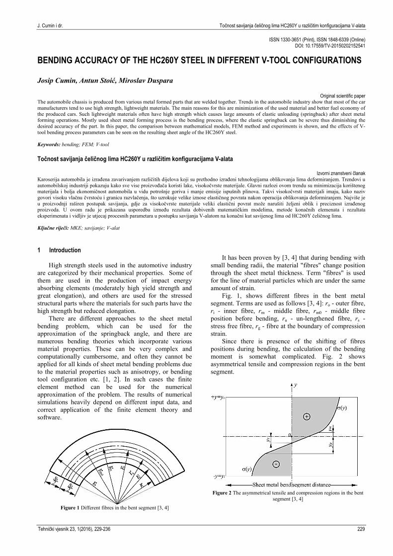
Since there is presence of the shifting of fibres positions during bending, the calculation of the bending moment is somewhat complicated. Fig. 2 shows asymmetrical tensile and compression regions in the bent segment.
Figure 2 The asymmetrical tensile and compression regions in the bent
segment [3, 4]
Bending accuracy of the HC260Y steel in different V-tool configurations J. Cumin et al.
230 Technical Gazette 23, 1(2016), 229-236
The stress function σ(y) from Fig. 2 follows the stress-strain curve of the material, and variables marked with the y designate distance of the fibres (Fig. 1) from the position of the original middle fibre.
The distances from the middle fibre are for: ys – stress free fibre, yg – fibre at the boundary of elastic/plastic compression strain, ym – fibre at the boundary of elastic/plastic tensile strain.
This asymmetrical stress distribution across thickness of the material, along with the mathematical description of bending process leads to the complicated mathematical models. Thus, the bending moment for plane strain bending (where one axis has much bigger dimension than other two) can be calculated with the use of the following term [5]:
(1)
where σeqv is equivalent stress, M is the bending moment and the parameter b is the sheet width. All other expression members are visible from Fig. 2.
Much work has been done in this area to make better mathematical descriptions of the sheet metal bending. D. Leu used material anisotropy for development of mathematical models and evaluation of bendability of anisotropic materials with asymmetric bend length [6]. J. Lee et al. proposed a constitutive mathematical model based on anisotropic hardening in FEM simulations and its performance was tested with conventional material strain hardening laws [7]. F. Zemin and M. Jianhua studied springback prediction of air bending of high strength steel sheets with genetic algorithm method and back propagation neural network approach method. They have conducted series of experiments, from which neural network was "trained" to find optimal bending process parameters [8].
S. Mohammadi et al. studied analytical, FEM and genetic algorithm results of springback in the four point bending of multi-layer sheets [9]. This work includes comparison between finite element method approach, theoretical bending problem approach and the results of the sheet metal V-bending experiments. 2 Mathematical V-bending model
The bending in the V-tool can be observed as two
similar processes, one which is air bending (basically pure bending moment), and the other one in which coining or calibration takes place.
This coining process is mathematically very difficult to approximate due to the complex stresses and strains.
It has been shown in previous researches that the main process parameters are: punch radius rp, punch width wp, die width w, die radius rd, sheet thickness s, punch speed vp, coefficient of friction μ [10, 11]. Besides the mentioned process parameters, the material behaviour also has influence on the springback, through strain
hardening exponent n and normal anisotropy of the sheet R.
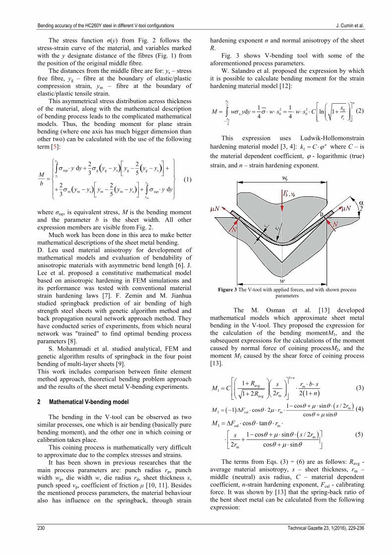
Fig. 3 shows V-bending tool with some of the aforementioned process parameters.
W. Salandro et al. proposed the expression by which it is possible to calculate bending moment for the strain hardening material model [12]:
0
0
22 2 0
x 0 0i
2
1 1d ln 14 4
s n
s
sM w y y w s w s Cr
s s−
= = ⋅ ⋅ = ⋅ ⋅ ⋅ + ∫ (2)
This expression uses Ludwik-Hollomonstrain
hardening material model [3, 4]: fnk C ϕ= ⋅ where C – is
the material dependent coefficient, ϕ - logarithmic (true) strain, and n – strain hardening exponent.
Figure 3 The V-tool with applied forces, and with shown process
parameters
The M. Osman et al. [13] developed mathematical models which approximate sheet metal bending in the V-tool. They proposed the expression for the calculation of the bending momentM1, and the subsequent expressions for the calculations of the moment caused by normal force of coining processM2, and the moment M3 caused by the shear force of coining process [13].
( )
1
avg m1
mavg
12 2 11 2
n
R r b ssM Cr nR
+ + ⋅ ⋅ = ⋅ + +
(3)
( ) ( )m2 cal m
1 cos sin / 21 cos 2
cos sins r
M F rθ m θ
θ mθ m θ
− + ⋅ ⋅= − ∆ ⋅ ⋅ ⋅ ⋅
+(4)
( )3 cal m
m
m
cos tan
1 cos sin / 22 cos sin
M F r
s rsr
θ θ
θ m θθ m θ
= ∆ ⋅ ⋅ ⋅ ⋅
− + ⋅ ⋅ ⋅ + + ⋅
(5)
The terms from Eqs. (3) ÷ (6) are as follows: Ravg -
average material anisotropy, s – sheet thickness, rm – middle (neutral) axis radius, C – material dependent coefficient, n-strain hardening exponent, Fcal - calibrating force. It was shown by [13] that the spring-back ratio of the bent sheet metal can be calculated from the following expression:
J. Cumin i dr. Točnost savijanja čeličnog lima HC260Y u različitim konfiguracijama V-alata
Tehnički vjesnik 23, 1(2016), 229-236 231
( )
( ) ( )
2
2m
1
avg
mavg
1
m
m
m
23 21
111 21 2
1 tancos 2
1 cos sin / 2tan tan 2
2 cos sin
n
n
E srC
R sn rR
n w se s r
s rsr
θθ n
w θθ
θ m θθ θ m
θ m θ
−
+
−
∆ = ⋅ ⋅−
+ + + ⋅ − − + ⋅ ⋅
− + ⋅ ⋅ ⋅ + + ⋅ + ⋅
(6)
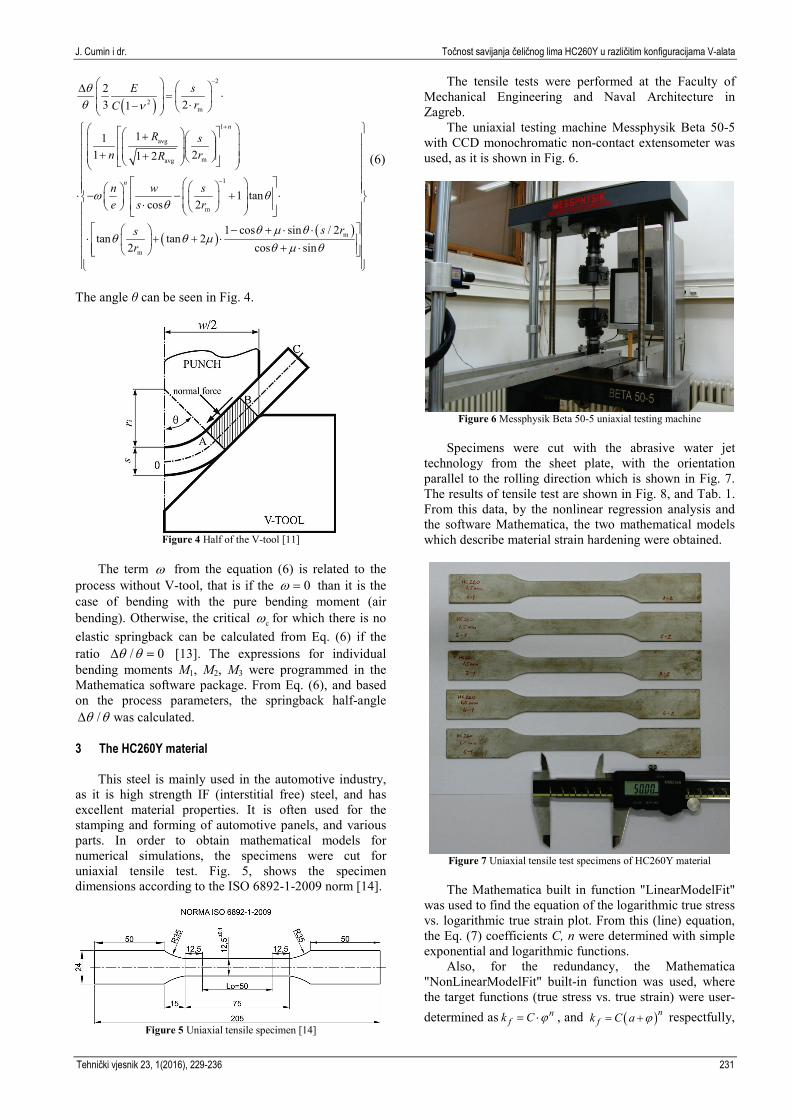
The angle θ can be seen in Fig. 4.
Figure 4 Half of the V-tool [11]
The term w from the equation (6) is related to the
process without V-tool, that is if the 0w = than it is the case of bending with the pure bending moment (air bending). Otherwise, the critical cw for which there is no elastic springback can be calculated from Eq. (6) if the ratio / 0θ θ∆ = [13]. The expressions for individual bending moments M1, M2, M3 were programmed in the Mathematica software package. From Eq. (6), and based on the process parameters, the springback half-angle
/θ θ∆ was calculated. 3 The HC260Y material
This steel is mainly used in the automotive industry,
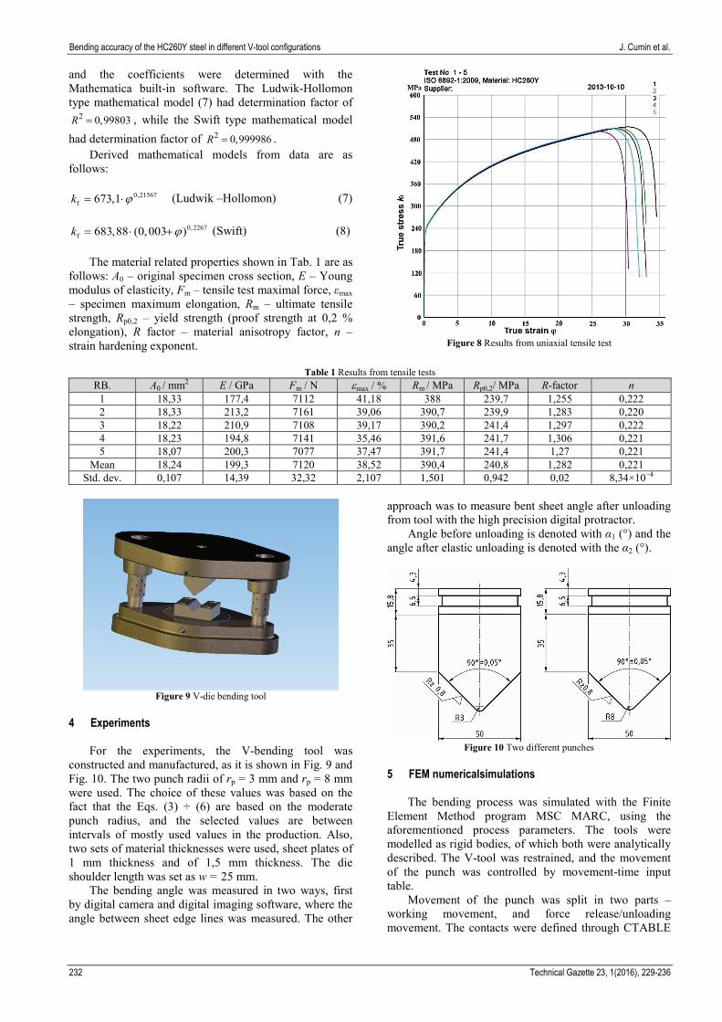
as it is high strength IF (interstitial free) steel, and has excellent material properties. It is often used for the stamping and forming of automotive panels, and various parts. In order to obtain mathematical models for numerical simulations, the specimens were cut for uniaxial tensile test. Fig. 5, shows the specimen dimensions according to the ISO 6892-1-2009 norm [14].
Figure 5 Uniaxial tensile specimen [14]
The tensile tests were performed at the Faculty of Mechanical Engineering and Naval Architecture in Zagreb.
The uniaxial testing machine Messphysik Beta 50-5 with CCD monochromatic non-contact extensometer was used, as it is shown in Fig. 6.
Figure 6 Messphysik Beta 50-5 uniaxial testing machine
Specimens were cut with the abrasive water jet
technology from the sheet plate, with the orientation parallel to the rolling direction which is shown in Fig. 7. The results of tensile test are shown in Fig. 8, and Tab. 1. From this data, by the nonlinear regression analysis and the software Mathematica, the two mathematical models which describe material strain hardening were obtained.
Figure 7 Uniaxial tensile test specimens of HC260Y material
The Mathematica built in function "LinearModelFit"
was used to find the equation of the logarithmic true stress vs. logarithmic true strain plot. From this (line) equation, the Eq. (7) coefficients C, n were determined with simple exponential and logarithmic functions.
Also, for the redundancy, the Mathematica "NonLinearModelFit" built-in function was used, where the target functions (true stress vs. true strain) were user-determined as n
fk C ϕ= ⋅ , and ( )nfk C a ϕ= + respectfully,
Bending accuracy of the HC260Y steel in different V-tool configurations J. Cumin et al.
232 Technical Gazette 23, 1(2016), 229-236
and the coefficients were determined with the Mathematica built-in software. The Ludwik-Hollomon type mathematical model (7) had determination factor of
2 0,99803R = , while the Swift type mathematical model had determination factor of 2 0,999986R = .
Derived mathematical models from data are as follows:
0,21567
f 673,1k ϕ= ⋅ (Ludwik –Hollomon) (7)
0,2267f 683,88 (0,003 )k ϕ= ⋅ + (Swift) (8)
The material related properties shown in Tab. 1 are as
follows: A0 – original specimen cross section, E – Young modulus of elasticity, Fm – tensile test maximal force, εmax – specimen maximum elongation, Rm – ultimate tensile strength, Rp0,2 – yield strength (proof strength at 0,2 % elongation), R factor – material anisotropy factor, n – strain hardening exponent.
Figure 8 Results from uniaxial tensile test
Table 1 Results from tensile tests
RB. A0 / mm2 E / GPa Fm / N εmax / % Rm / MPa Rp0,2/ MPa R-factor n 1 18,33 177,4 7112 41,18 388 239,7 1,255 0,222 2 18,33 213,2 7161 39,06 390,7 239,9 1,283 0,220 3 18,22 210,9 7108 39,17 390,2 241,4 1,297 0,222 4 18,23 194,8 7141 35,46 391,6 241,7 1,306 0,221 5 18,07 200,3 7077 37,47 391,7 241,4 1,27 0,221
Mean 18,24 199,3 7120 38,52 390,4 240,8 1,282 0,221 Std. dev. 0,107 14,39 32,32 2,107 1,501 0,942 0,02 8,34×10⁻⁴
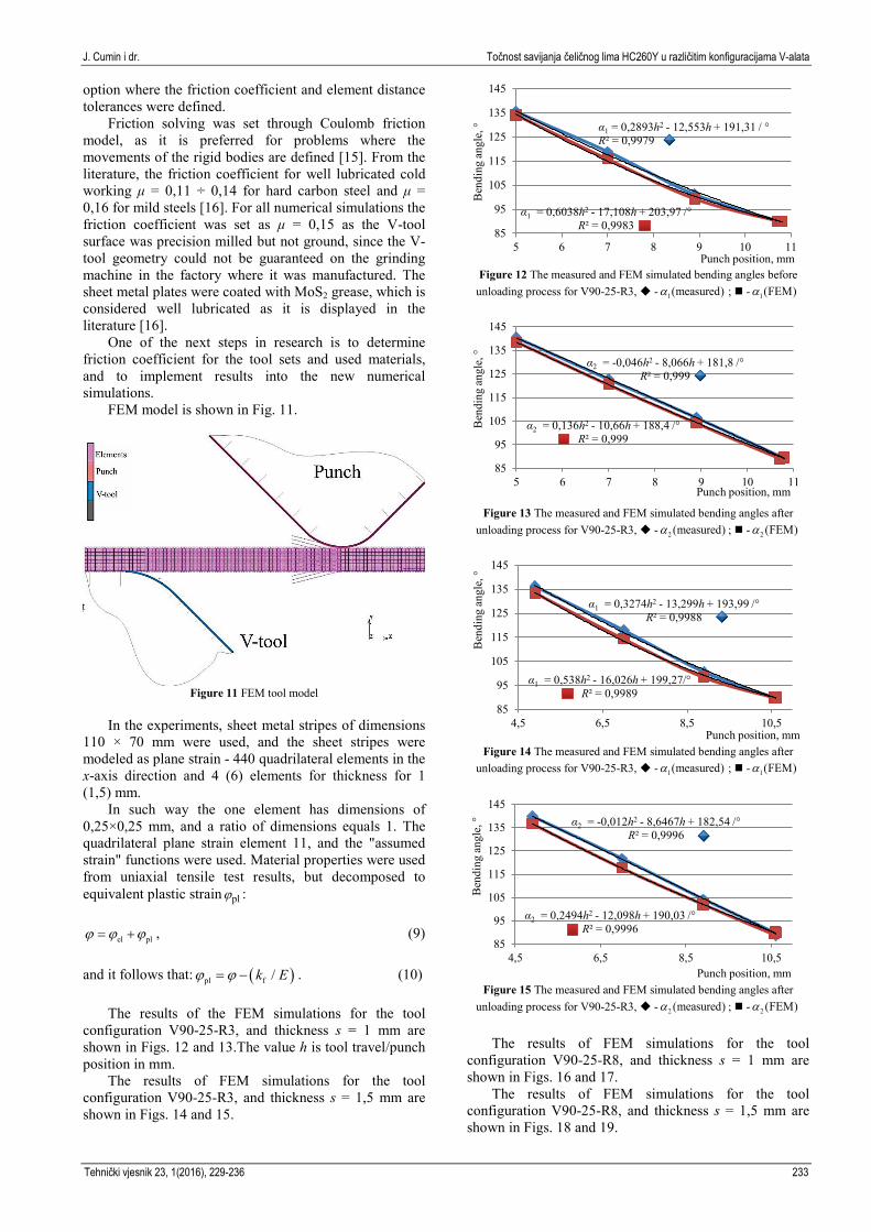
Figure 9 V-die bending tool
4 Experiments
For the experiments, the V-bending tool was
constructed and manufactured, as it is shown in Fig. 9 and Fig. 10. The two punch radii of rp = 3 mm and rp = 8 mm were used. The choice of these values was based on the fact that the Eqs. (3) ÷ (6) are based on the moderate punch radius, and the selected values are between intervals of mostly used values in the production. Also, two sets of material thicknesses were used, sheet plates of 1 mm thickness and of 1,5 mm thickness. The die shoulder length was set as w = 25 mm.
The bending angle was measured in two ways, first by digital camera and digital imaging software, where the angle between sheet edge lines was measured. The other
approach was to measure bent sheet angle after unloading from tool with the high precision digital protractor.
Angle before unloading is denoted with α1 (°) and the angle after elastic unloading is denoted with the α2 (°).
Figure 10 Two different punches
5 FEM numericalsimulations
The bending process was simulated with the Finite
Element Method program MSC MARC, using the aforementioned process parameters. The tools were modelled as rigid bodies, of which both were analytically described. The V-tool was restrained, and the movement of the punch was controlled by movement-time input table.
Movement of the punch was split in two parts – working movement, and force release/unloading movement. The contacts were defined through CTABLE
J. Cumin i dr. Točnost savijanja čeličnog lima HC260Y u različitim konfiguracijama V-alata
Tehnički vjesnik 23, 1(2016), 229-236 233
option where the friction coefficient and element distance tolerances were defined.
Friction solving was set through Coulomb friction model, as it is preferred for problems where the movements of the rigid bodies are defined [15]. From the literature, the friction coefficient for well lubricated cold working μ = 0,11 ÷ 0,14 for hard carbon steel and μ = 0,16 for mild steels [16]. For all numerical simulations the friction coefficient was set as μ = 0,15 as the V-tool surface was precision milled but not ground, since the V-tool geometry could not be guaranteed on the grinding machine in the factory where it was manufactured. The sheet metal plates were coated with MoS2 grease, which is considered well lubricated as it is displayed in the literature [16].
One of the next steps in research is to determine friction coefficient for the tool sets and used materials, and to implement results into the new numerical simulations.
FEM model is shown in Fig. 11.
Figure 11 FEM tool model
In the experiments, sheet metal stripes of dimensions
110 × 70 mm were used, and the sheet stripes were modeled as plane strain - 440 quadrilateral elements in the x-axis direction and 4 (6) elements for thickness for 1 (1,5) mm.
In such way the one element has dimensions of 0,25×0,25 mm, and a ratio of dimensions equals 1. The quadrilateral plane strain element 11, and the "assumed strain" functions were used. Material properties were used from uniaxial tensile test results, but decomposed to equivalent plastic strain plϕ :
el plϕ ϕ ϕ= + , (9) and it follows that: ( )pl f /k Eϕ ϕ= − . (10)
The results of the FEM simulations for the tool
configuration V90-25-R3, and thickness s = 1 mm are shown in Figs. 12 and 13.The value h is tool travel/punch position in mm.
The results of FEM simulations for the tool configuration V90-25-R3, and thickness s = 1,5 mm are shown in Figs. 14 and 15.
Figure 12 The measured and FEM simulated bending angles before
unloading process for V90-25-R3, - 1(measured)a ; - 1(FEM)a
Figure 13 The measured and FEM simulated bending angles after
unloading process for V90-25-R3, - 2 (measured)a ; - 2 (FEM)a
Figure 14 The measured and FEM simulated bending angles after
unloading process for V90-25-R3, - 1(measured)a ; - 1(FEM)a
Figure 15 The measured and FEM simulated bending angles after
unloading process for V90-25-R3, - 2 (measured)a ; - 2 (FEM)a
The results of FEM simulations for the tool
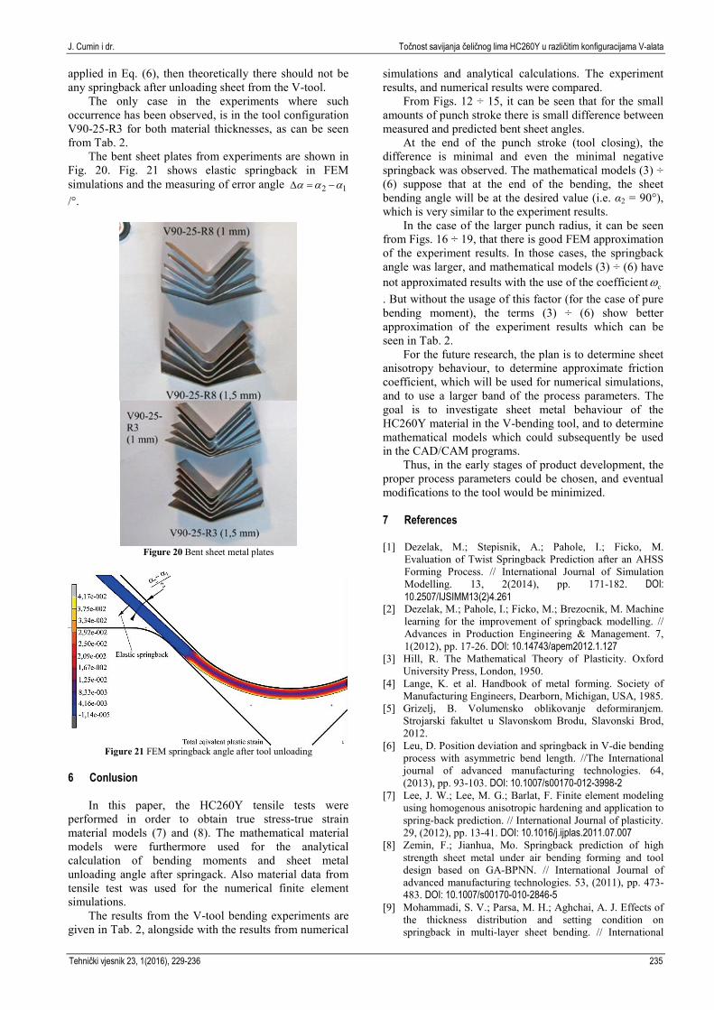
configuration V90-25-R8, and thickness s = 1 mm are shown in Figs. 16 and 17.
The results of FEM simulations for the tool configuration V90-25-R8, and thickness s = 1,5 mm are shown in Figs. 18 and 19.
α1 = 0,2893h2 - 12,553h + 191,31 / ° R² = 0,9979
α1 = 0,6038h2 - 17,108h + 203,97 /° R² = 0,9983
85
95
105
115
125
135
145
5 6 7 8 9 10 11
Ben
ding
ang
le, °
Punch position, mm
α2 = -0,046h2 - 8,066h + 181,8 /° R² = 0,999
α2 = 0,136h2 - 10,66h + 188,4 /° R² = 0,999
85
95
105
115
125
135
145
5 6 7 8 9 10 11B
endi
ng a
ngle
, °
Punch position, mm
α1 = 0,3274h2 - 13,299h + 193,99 /° R² = 0,9988
α1 = 0,538h2 - 16,026h + 199,27/° R² = 0,9989
85
95
105
115
125
135
145
4,5 6,5 8,5 10,5
Ben
ding
ang
le, °
Punch position, mm
α2 = -0,012h2 - 8,6467h + 182,54 /° R² = 0,9996
α2 = 0,2494h2 - 12,098h + 190,03 /° R² = 0,9996
85
95
105
115
125
135
145
4,5 6,5 8,5 10,5
Ben
ding
ang
le, °
Punch position, mm
Bending accuracy of the HC260Y steel in different V-tool configurations J. Cumin et al.
234 Technical Gazette 23, 1(2016), 229-236
Figure 16 The measured and FEM simulated bending angles after
unloading process for V90-25-R8, - 1(measured)a ; - 1(FEM)a
Figure 17 The measured and FEM simulated bending angles after
unloading process for V90-25-R8, - 2 (measured)a ; - 2 (FEM)a
From Figs. 12 ÷ 15 it is visible that there is somewhat
larger difference between measured angle and numerically obtained one for the lower values of punch stroke and vice versa. For all the cases shown in Figs. 12 ÷ 15, the sheet was bent to 90° and then unloaded to measure elastic springback angle α2.
Figure 18 The measured and FEM simulated bending angles after
unloading process for V90-25-R8, - 1(measured)a ; - 1(FEM)a
Figure 19. The measured and FEM simulated bending angles after
unloading process for V90-25-R8, - 2 (measured)a ; - 2 (FEM)a .
For both sheet thicknesses there was minimal
springback, depending on the punch force, even minimal negative springback was observed, as it is shown in Tab. 2.
Table 2 Results from experiments, FEM simulations and mathematical Eqs. (3) ÷ (6)
No. Punch stroke,
mm
α1 / ° |Δα1| / °
α2 / ° |Δα2| / °
Eqs. (3) ÷ (6) ωc
Meas. FEM Meas. Image meas. FEM α2 / ° |Δα2| / °
V90-25-R3, s = 1 mm 1 10,79 90 90 0 89,7 89,8 89,6 0,1 91,9 2,3 0,006485 2 10,8 90 90 0 89,2 89,2 89,7 0,5 91,9 2,7 0,006485
V90-25-R3, s = 1,5 mm 3 10,6 90 90 0 89,8 89,8 90,2 0,4 91,46 1,66 0,0121 4 10,61 90 90 0 88,8 88,8 90,1 0,3 91,46 2,66 0,0121
V90-25-R8, s = 1 mm 5 8,75 90 90 0 95,3 95,2 94,1 1,2 93,8 1,5 0,00253 6 8,78 90 90 0 94,8 94,8 94 0,8 93,8 1 0,00253
V90-25-R8, s = 1,5 mm 7 8,5 90 90 0 92,4 92,4 92 0,4 92,83 0,43 0,00476 8 8,5 90 90 0 92,3 92,3 92 0,3 92,83 0,53 0,00476
From Figs. 16 ÷ 19, it is visible that numerical FEM
simulation better approximates the bending process for the small punch strokes as opposed to the tool configuration V90-25-R3. In this tool configuration (V90-25-R8), the higher amount of springback was observed after tool closing, and subsequent tool unloading where the springback takes place. The data from these cases is also shown in Tab. 2.
Using the process parameters and Eqs. (3) ÷ (6), along with the determined material model (7), the calculations were performed and the results are shown in
Tab. 2 for comparison with the experiments results and numerical simulations results.
From Tab. 2, it can be seen that the difference between FEM results and experiments is relatively small, as compared with the results from the mathematical calculations (3) ÷ (6). It is important to notice that the column with results from the Eqs. (3) ÷ (6) is related to the elastic unloading without coining process.
The next column displays data for ωc, the coefficient which is related with the coining force, if the number is higher so should be the coining force. If the factor ωc is
α1 = -0,3228h2 - 7,274h + 178,36 /° R² = 1
α1 = -0,1924h2 - 8,6259h + 180,13 /° R² = 0,9999
90
100
110
120
130
140
150
4 5 6 7 8 9
Ben
ding
ang
le, °
Punch position, mm
α2 = -0,478h2 - 5,0608h + 176,1 /° R² = 0,9997
α2 = -0,2165h2 - 8,4628h + 186,08 /° R² = 1
90
100
110
120
130
140
150
160
4 5 6 7 8 9
Ben
ding
ang
le, °
Punch position, mm
α1 = -0,2455h2 - 8,6058h + 181,3 /° R² = 0,999
α1 = -0,3866h2 - 6,6343h + 174,69 /° R² = 0,9992
90
100
110
120
130
140
150
4 5 6 7 8 9
Ben
ding
ang
le, °
Punch position, mm
α2 = -0,5585h2 - 4,7383h + 172,97 /° R² = 0,9993
α2 = -11,824h + 193,49 R² = 0,9966
90
100
110
120
130
140
150
4 5 6 7 8 9B
endi
ng a
ngle
, °
Punch position, mm
J. Cumin i dr. Točnost savijanja čeličnog lima HC260Y u različitim konfiguracijama V-alata
Tehnički vjesnik 23, 1(2016), 229-236 235
applied in Eq. (6), then theoretically there should not be any springback after unloading sheet from the V-tool.
The only case in the experiments where such occurrence has been observed, is in the tool configuration V90-25-R3 for both material thicknesses, as can be seen from Tab. 2.
The bent sheet plates from experiments are shown in Fig. 20. Fig. 21 shows elastic springback in FEM simulations and the measuring of error angle 2 1a a a∆ = −
/°.
Figure 20 Bent sheet metal plates
Figure 21 FEM springback angle after tool unloading
6 Conlusion
In this paper, the HC260Y tensile tests were
performed in order to obtain true stress-true strain material models (7) and (8). The mathematical material models were furthermore used for the analytical calculation of bending moments and sheet metal unloading angle after springack. Also material data from tensile test was used for the numerical finite element simulations.
The results from the V-tool bending experiments are given in Tab. 2, alongside with the results from numerical
simulations and analytical calculations. The experiment results, and numerical results were compared.
From Figs. 12 ÷ 15, it can be seen that for the small amounts of punch stroke there is small difference between measured and predicted bent sheet angles.
At the end of the punch stroke (tool closing), the difference is minimal and even the minimal negative springback was observed. The mathematical models (3) ÷ (6) suppose that at the end of the bending, the sheet bending angle will be at the desired value (i.e. α2 = 90°), which is very similar to the experiment results.
In the case of the larger punch radius, it can be seen from Figs. 16 ÷ 19, that there is good FEM approximation of the experiment results. In those cases, the springback angle was larger, and mathematical models (3) ÷ (6) have not approximated results with the use of the coefficient cw. But without the usage of this factor (for the case of pure bending moment), the terms (3) ÷ (6) show better approximation of the experiment results which can be seen in Tab. 2.
For the future research, the plan is to determine sheet anisotropy behaviour, to determine approximate friction coefficient, which will be used for numerical simulations, and to use a larger band of the process parameters. The goal is to investigate sheet metal behaviour of the HC260Y material in the V-bending tool, and to determine mathematical models which could subsequently be used in the CAD/CAM programs.
Thus, in the early stages of product development, the proper process parameters could be chosen, and eventual modifications to the tool would be minimized. 7 References
[1] Dezelak, M.; Stepisnik, A.; Pahole, I.; Ficko, M.
Evaluation of Twist Springback Prediction after an AHSS Forming Process. // International Journal of Simulation Modelling. 13, 2(2014), pp. 171-182. DOI: 10.2507/IJSIMM13(2)4.261
[2] Dezelak, M.; Pahole, I.; Ficko, M.; Brezocnik, M. Machine learning for the improvement of springback modelling. // Advances in Production Engineering & Management. 7, 1(2012), pp. 17-26. DOI: 10.14743/apem2012.1.127
[3] Hill, R. The Mathematical Theory of Plasticity. Oxford University Press, London, 1950.
[4] Lange, K. et al. Handbook of metal forming. Society of Manufacturing Engineers, Dearborn, Michigan, USA, 1985.
[5] Grizelj, B. Volumensko oblikovanje deformiranjem. Strojarski fakultet u Slavonskom Brodu, Slavonski Brod, 2012.
[6] Leu, D. Position deviation and springback in V-die bending process with asymmetric bend length. //The International journal of advanced manufacturing technologies. 64, (2013), pp. 93-103. DOI: 10.1007/s00170-012-3998-2
[7] Lee, J. W.; Lee, M. G.; Barlat, F. Finite element modeling using homogenous anisotropic hardening and application to spring-back prediction. // International Journal of plasticity. 29, (2012), pp. 13-41. DOI: 10.1016/j.ijplas.2011.07.007
[8] Zemin, F.; Jianhua, Mo. Springback prediction of high strength sheet metal under air bending forming and tool design based on GA-BPNN. // International Journal of advanced manufacturing technologies. 53, (2011), pp. 473-483. DOI: 10.1007/s00170-010-2846-5
[9] Mohammadi, S. V.; Parsa, M. H.; Aghchai, A. J. Effects of the thickness distribution and setting condition on springback in multi-layer sheet bending. // International

Bending accuracy of the HC260Y steel in different V-tool configurations J. Cumin et al.
236 Technical Gazette 23, 1(2016), 229-236
Journal of engineering, science and technology. 3, (2011), pp. 225-235. DOI: 10.4314/ijest.v3i4.68555
[10] Thipprakmas, S. Finite element analysis on the coined-bead mechanism during the V-bending process. // Journal of Materials and Design. 32, (2011), pp. 4909-4917. DOI: 10.1016/j.matdes.2011.05.054
[11] Thipprakmas, S. Finite element analysis of punch height effect on V-bending angle. // Journal of Materials and Design. 31, (2010), pp. 1593-1598. DOI: 10.1016/j.matdes.2009.09.019
[12] Salandro, W.; Bunget, C.; Mears, L. Modeling and quantification of the electro-plastic effect when bending stainless steel sheet metal. // Proceedings of the 2010 International Manufacturing, Science and Engineering Conference, ASME, MSEC2010 12-15, 2010, Pennsylvania, USA, pp. 1-10.
[13] Osman, M.; Shazly, M.; El-Mokaddem, A.; Wifi, A.Springback prediction in V-die bending, modelling and experimentation.// AMME, Journal of achievements in materials and manufacturing engineering. 38, (2010), pp. 179-186.
[14] Norm: ISO 6892-1-2009. // International standard, Metallic materials tensile testing part 1: Method of test at room temperature, ISO 2009.
[15] MSC. Software Corporation. // MSC.MARC advanced course, U.S.A., 2003.
[16] Industrial press Inc. Machinery's handbook. // Industrial press Inc., New York, 2008. Authors’ addresses Josip Cumin, dr. sc. Mechanical Engineering Faculty in Slavonski Brod, Trg I. B. Mazuranic 2, 35000 Slavonski Brod, Croatia E-mail: [email protected] Antun Stoić, prof. dr. sc. Mechanical Engineering Faculty in Slavonski Brod, Trg I. B. Mazuranic 2, 35000 Slavonski Brod, Croatia E-mail: [email protected] Miroslav Duspara, dr. sc. Mechanical Engineering Faculty in Slavonski Brod, Trg I. B. Mazuranic 2, 35000 Slavonski Brod, Croatia E-mail: [email protected]