Embed Size (px)
DESCRIPTION
STM32F4 Advanced Peripherals
Citation preview

STM32F4
Advanced peripherals

DIGITAL CAMERA INTERFACE (DCMI)
Same as STM32F-2
DCMI Features The Digital Camera Interface has the following main features:
8-, 10-, 12- or 14-bit parallel interface
Continuous or snapshot mode
Crop feature
Supports the following data formats:
8/10/12/14- bit progressive scan: either monochrome or raw bayer
YCbCr 4:2:2 progressive scan
RGB 565 progressive video
Compressed data: JPEG
With a 48MHz PIXCLK and 8-bit parallel input data interface it is possible to receive:
up to 15fps uncompressed data stream in SXGA resolution (1280x1024) with 16-bit per pixel
up to 30fps uncompressed data stream in VGA resolution (640x480) with 16-bit per pixel
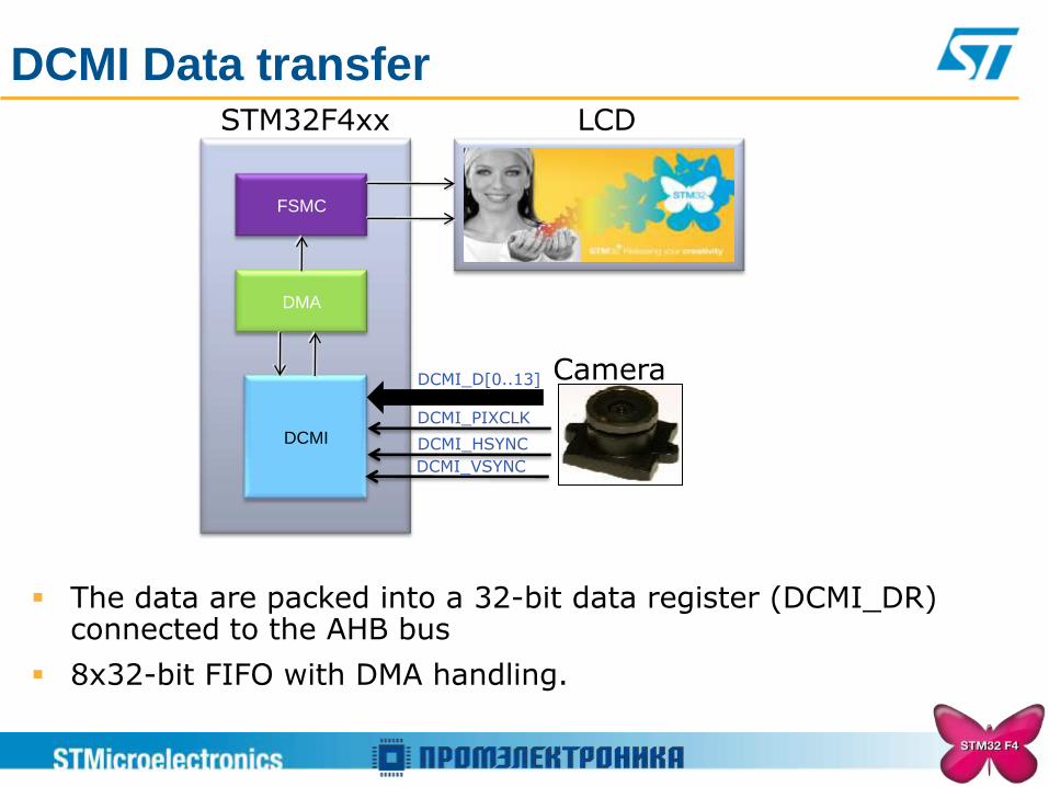
DCMI Data transfer
FSMC
DMA
DCMI
LCD STM32F4xx
DCMI_PIXCLK
DCMI_D[0..13]
DCMI_HSYNC
DCMI_VSYNC
Camera
The data are packed into a 32-bit data register (DCMI_DR) connected to the AHB bus
8x32-bit FIFO with DMA handling.

DCMI CROP feature The DCMI interface supports two types of capture:
The DCMI can select a rectangular window from the received image
The start coordinates and size are specified using two 32-bit registers DCMI_CWSTRT and DCMI_CWSIZE.
The size of the window is specified in number of pixel clocks (horizontal dimension) and in number of lines (vertical dimension)
Vertical start line count
Horizontal offset count
Vert
ical line c
ount
Capture count

CRYPTOGRAPHIC PROCESSOR
(CRYP)
Same as STM32F-2
Definitions
AES : Advanced Encryption Standard
DES : Data Encryption Standard
TDES : Triple Data Encryption Standard
Encryption/ Decryption modes
ECB : Electronic code book mode
CBC : Cipher block chaining mode or chained encryption
CTR : Counter mode (used for GCM : Galois Counter Mode) GCM is a combination of CTR and GHASH.

CRYP algorithms overview
AES DES TDES
Key sizes 128, 192 or 256 bits 64* bits * 8 parity bits
192***, 128** or 64* bits * 8 parity bits : Keying option 1
** 16 parity bits: Keying option 2
***24 parity bits: Keying option 3
Block sizes 128 bits 64 bits 64 bits
Time to process one
block
14 HCLK cycle for key = 128bits
16 HCLK cycle for key = 192bits
18 HCLK cycle for key = 256bits
16 HCLK cycles 48 HCLK cycles
Type block cipher block cipher block cipher
Structure Substitution-permutation
network Feistel network Feistel network
First published 1998 1977 (standardized
on January 1979) 1998 (ANS X9.52)
AES : Advanced Encryption Standard
DES : Data Encryption Standard TDES : Triple Data Encryption
Standard

CRYP Features (1/2)
Suitable for AES, DES and TDES enciphering and deciphering
operations
Runs at the same frequency as the CPU, up to 168 MHz.
DES/TDES
Direct implementation of simple DES algorithms (a single key, K1, is used)
Supports the ECB and CBC chaining algorithms
Supports 64-, 128- and 192-bit keys (including parity)
64-bit initialization vectors (IV) used in the CBC mode
16 HCLK cycles to process one 64-bit block in DES
48 HCLK cycles to process one 64-bit block in TDES

CRYP Features (2/2)
AES
Supports the ECB, CBC and CTR chaining algorithms
Supports 128-, 192- and 256-bit keys
128-bit initialization vectors (IV) used in the CBC and CTR modes
14, 16 or 18 HCLK cycles (depending on the key size) to transform one
128-bit block in AES
Common to DES/TDES and AES
IN and OUT FIFO (each with an 8-word depth, a 32-bit width,
corresponding to 4 DES blocks or 2 AES blocks)
Automatic data flow control with support of direct memory access (DMA)
(using 2 channels, one for incoming data the other for processed data)
Data swapping logic to support 1-, 8-, 16- or 32-bit data

Flags
CRYP Block Diagram
Key: 128-, 192- and 256-bit
Key: 64-bit
Key: 64-, 128- and 192-bit
TDES
AES
DES
CRYPTO Processor
Inp
ut
FIF
O
Ou
tpu
t F
IFO
Data
sw
ap
pin
g
Data
sw
ap
pin
g
ECB CBC CTR
DMA request
for incoming
data transfer
DMA request
for outgoing
data transfer
BUSY OFFU OFNE IFNF IFEM
ECB CBC
ECB CBC
OUTRIS INRIS
CRYPTO Global interrupt
(NVIC)
OUTIM INIM OUTMIS INMIS

ECB Encryption
CRYPTO
Encryption
Algorithm
Plain Text1
Cipher Text1
CRYPTO
Encryption
Algorithm
Plain Text2
Cipher Text2
key key
CRYPTO
Encryption
Algorithm
Plain Text3
Cipher Text3
key
The simplest of the encryption modes is the Electronic codebook (ECB) mode.
The message is divided into blocks and each block is encrypted separately.
The disadvantage of this method is that identical plaintext blocks are encrypted
into identical cipher text blocks; thus, it does not hide data patterns well. To avoid
this weakness, CBC or CTR modes can be used.

CRYPTO
Encryption
Algorithm
Plain
Text1
Cipher
Text1
Initialization
Vector
CRYPTO
Encryption
Algorithm
Plain
Text2
Cipher
Text2
key key
CRYPTO
Decryption
Algorithm
Plain
Text1
Cipher
Text1
CRYPTO
Decryption
Algorithm
Plain
Text2
Cipher
Text2
key key
Initialization
Vector
Encryption Decryption
CBC mode of operation was invented by IBM in 1976.
In the CBC mode, each block of plaintext is XORed with the previous cipher text
block before being encrypted.
This way, each cipher text block is dependent on all plaintext blocks processed up
to that point.
To make each message unique, an initialization vector must be used in the first
block.
Cipher block chaining mode (CBC)
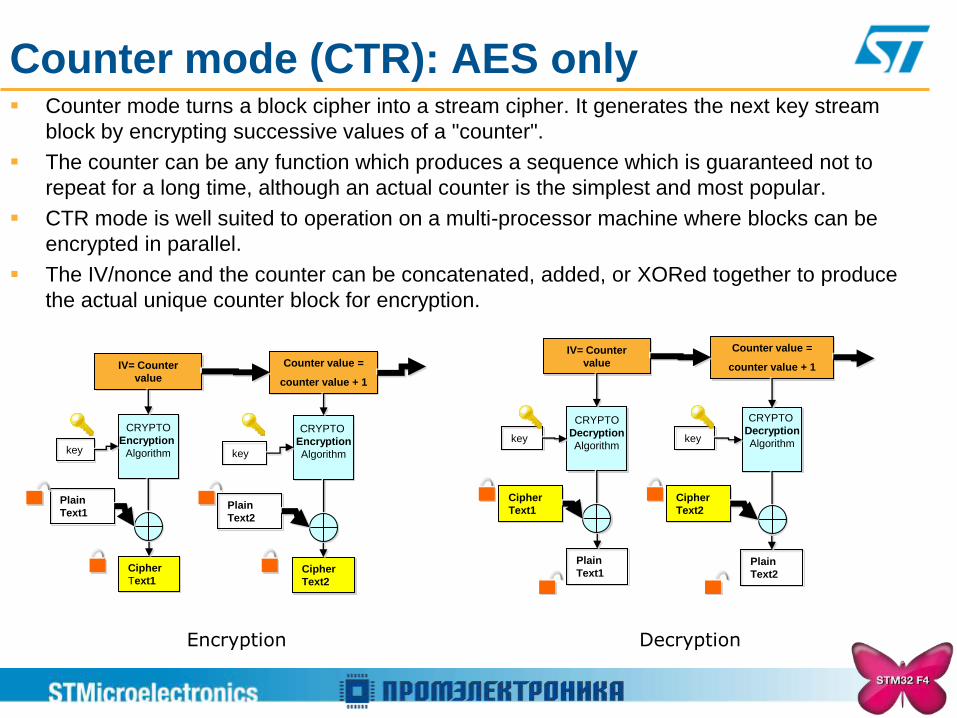
Counter mode (CTR): AES only Counter mode turns a block cipher into a stream cipher. It generates the next key stream
block by encrypting successive values of a "counter".
The counter can be any function which produces a sequence which is guaranteed not to
repeat for a long time, although an actual counter is the simplest and most popular.
CTR mode is well suited to operation on a multi-processor machine where blocks can be
encrypted in parallel.
The IV/nonce and the counter can be concatenated, added, or XORed together to produce
the actual unique counter block for encryption.
Encryption Decryption
CRYPTO
Encryption
Algorithm
Cipher
Text1
IV= Counter
value
CRYPTO
Encryption
Algorithm
Cipher
Text2
Counter value =
counter value + 1
key key
Plain
Text1 Plain
Text2
CRYPTO
Decryption
Algorithm
Plain
Text1
IV= Counter
value
CRYPTO
Decryption
Algorithm
Plain
Text2
Counter value =
counter value + 1
key key
Cipher
Text1
Cipher
Text2

CRYP throughput
AES-128 AES-192 AES-256 DES TDES
HW
Theoretical 192.00 168.00 149.33 84.00 28.00
HW Without
DMA 72.64 72.64 62.51 43.35 16.00
HW With
DMA 128.00 168.00 149.33 84.00 28.00
Pure SW 1.38 1.14 0.96 0.74 0.25
Throughput in MB/s at 168 MHz for the various algorithms and implementations

CRYP and DMA
The cryptographic processor provides an interface to connect to the DMA controller. The
DMA operation is controlled through the CRYP DMA control register, CRYP_DMACR.
2 requests are available
Request DMA for outgoing data transfer from FIFO OUT
Request DMA for incoming data transfer to FIFO IN
All request signals are de-asserted if the CRYP peripheral is disabled or the DMA enable bit
is cleared (DIEN bit for the IN FIFO and DOEN bit for the OUT FIFO in the CRYP_DMACR
register).
Important to know
The DMA controller must be configured to perform burst of 4 words or less. Otherwise
some data could be lost.
In order to let the DMA controller empty the OUT FIFO before filling up the IN FIFO, the
OUTDMA Stream should have a higher priority than the INDMA Stream.

RANDOM NUMBER GENERATOR
(RNG)
Same as STM32F-2
RNG Features
32-bit random numbers, produced by an analog generator (based on a
continuous analog noise)
Clocked by a dedicated clock (PLL48CLK)
40 periods of the PLL48CLK clock signal between two consecutive random
numbers
Can be disabled to reduce power-consumption
Provide a success ratio of more than 85% to FIPS 140-2 (Federal Information
Processing Standards Publication 140-2) tests for a sequence of 20 000
bits.
5 Flags 1 flag occurs when Valid random Data is ready
2 Flags to an abnormal sequence occurs on the seed.
2 flags for frequency error (PLL48CLK clock is too low).
1 interrupt To indicate an error (an abnormal sequence error or a frequency error)
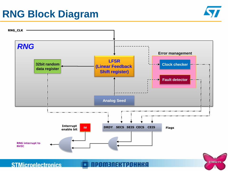
RNG Block Diagram
RNG
RNG_CLK
Flags Interrupt enable bit
RNG interrupt to NVIC
IM DRDY
LFSR
(Linear Feedback
Shift register)
Analog Seed
32bit random
data register Clock checker
Fault detector
CEIS SEIS SECS CECS
Error management
HASH PROCESSOR (HASH)
Same as STM32F-2

Definitions
A cryptographic hash function is a deterministic procedure that
takes an arbitrary block of data and returns a fixed-size bit string, the
(cryptographic) hash value, such that an accidental or intentional
change to the data will change the hash value. The data to be
encoded is often called the "message", and the hash value is
sometimes called the message digest or simply digest.
Message
(data to be encoded)
arbitrary block of data
fixed-size bit string
Digest Hash function
Definitions
SHA-1 : the Secure Hash algorithm
MD5 : Message-Digest algorithm 5 hash algorithm
HMAC : (keyed-Hash Message Authentication Code) algorithm
HASH : Computes a SHA-1 and MD5 message digest for messages of up
to (264 – 1) bits
HMAC algorithms provide a way of authenticating messages by means of
hash functions.
HMAC algorithms consist in calling the SHA-1 or MD5 hash function twice
on message in combination with a secret value (key).
HASH Features Suitable for Integrity check and data authentication applications, compliant with:
FIPS PUB 180-2 (Federal Information Processing Standards Publication 180-2)
Secure Hash Standard specifications (SHA-1)
IETF RFC 1321 (Internet Engineering Task Force Request For Comments
number 1321) specifications (MD5)
AHB slave peripheral
Fast computation of SHA-1 and MD5 :
66 HCLK clock cycles in SHA-1
50 HCLK clock cycles in MD5
5 × (32-bit) words (H0, H1, H2, H3 and H4) for output message digest, reload able
to continue interrupted message digest computation
Automatic data flow control with support for direct memory access (DMA)
32-bit data words for input data, supporting word, half-word, byte and bit bit-string
representations, with little-endian data representation only

HASH Block Diagram
Flags
MD5 SHA-1
HASH
HASH Processor
Input
FIFO
Data
sw
ap
pin
g
DMA
request
BUSY DMAS DCIS DINIS
HASH Global interrupt
(NVIC)
DCIM
DINIM
HMAC
Message
Digest
H0..H4
5x32bit 16 x
32bit

MD5 SHA1
HW Theoretical 162.9 131.12
HW Without DMA 77.35 71.68
HW With DMA 105.40 91.11
Pure SW 11.52 5.15
Throughput in MB/s at 168 MHz for SHA-1 and MD5 algorithms with different
implementations
HASH throughput

Thank you
www.st.com/stm32f4