Embed Size (px)
Citation preview

Steven R. HansenDepartment of Materials Science and Engineering,
The Ohio State University,
2041 College Road,
Columbus, OH 43210
e-mail: [email protected]
Anupam Vivek1
Department of Materials Science and Engineering,
The Ohio State University,
2041 College Road,
Columbus, OH 43210
e-mail: [email protected]
Glenn S. DaehnDepartment of Materials Science and Engineering,
The Ohio State University,
2041 College Road,
Columbus, OH 43210
e-mail: [email protected]
Impact Welding of AluminumAlloys 6061 and 5052 byVaporizing Foil Actuators:Heat-Affected Zone Sizeand Peel StrengthJoining aluminum alloy sheets is increasingly important in manufacturing. Traditionalwelding techniques create a heat-affected zone (HAZ) around the joint; however, solid-state joining methods such as impact welding produce joints without significant heat.Here, electrically vaporized foil actuators (VFA) provided the high-pressure pulsesneeded for impact welding. 0.96 mm thick AA6061-T6 and 0.76 mm thick AA5052 werejoined in lap and spotlike configurations, at a variety of impact velocities. The weldsfailed in coach-peel outside the joint interface. The 5052 hardened within 100 lm of theinterface. The 6061-T6 may have softened slightly within 50 lm of the interface.[DOI: 10.1115/1.4030934]
Introduction
Aluminum alloys combine low density and corrosion resistancewith good mechanical properties after metallurgical strengtheningmechanisms are applied. The high strength-to-density ratio of alu-minum alloys makes them popular in industries such as automo-tive and aerospace manufacturing [1,2]. Body panels andstructural components, such as decklids and roof rails, are increas-ingly being designed out of aluminum instead of steel [3]. For thatreason, the production of strong joints between aluminum compo-nents has become increasingly important.
Traditional fusion welding (via shielded metal arc welding, gasmetal arc welding, or gas tungsten arc welding) and resistancespot welding produce a HAZ around the weld area [4]. Recentadvanced techniques, such as cold metal transfer joining, reduceheat input, but do not eliminate the HAZ [5]. Some degree ofHAZ is even observed in friction stir welding, a solid-state weld-ing technique [6]. In the HAZ, which can span a few millimeters[2,6] or even centimeters [4,7] from the weld perimeter, the metaltemperature is substantially increased during the welding process.In age-hardened Al alloys like 6061-T6, heat from welding canlead to overaging of the alloy, causing a loss of material strength[4]. In work-hardened alloys like 5052, strength is reduced byannealing of the material. As a result, materials become more sus-ceptible to failure in the HAZ around the weld.
Impact welding, which produces a solid-state joint with mini-mal melting at the interface, is a good candidate for producingHAZ-free joints [8]. In this technique, which has been practicedwith explosives since the 1950s, one metal sheet (called a flyer) isdriven by a high-pressure pulse to a high velocity, in order toimpact another sheet (called a target) at an angle. At the point ofimpact, hydrodynamic behavior of the metals’ surfaces results inthe ejection of their surfaces as a jet. The jetted material containssurface oxides and other impurities and leaves behind clean metal-lic surfaces in high-pressure contact with each other [9]. Thisleads to the formation of a metallurgical bond between the twoparent sheets as the gap between them collapses and the impactpoint progresses to the edge of the sheets. The weld interface
morphology can range from flat to varying degrees of waviness,and may or may not contain pores or a layer of intermetallic com-pounds, all depending on the material properties and the impactangle and velocity [10–12]. There thus exists a “welding window”of parameters that produce a strong weld for a given materialcombination [13,14]. The mechanism of formation of the wavymorphology is debated [15,16]; however, the purpose of this paperis not to critique or validate any particular theory.
Explosive welding (EXW) is useful for joining centimeter-thickflyers to targets as thick or thicker; however, this method performspoorly at smaller scales [17]. Magnetic pulse welding (MPW)—also known as electromagnetic (EM) impact welding—has provenuseful for aluminum flyers up to 1 mm thick with targets of variedthicknesses [18]. MPW joints can exceed the base metal strength,as shown by Shribman et al. with AA7075-T6 [19] and Okagawaand Aizawa with AA1050-O [20]. Kore et al. also EM weldedAA1050-O to itself [21] as well as to heat treated Al–Li alloy1441 [22]. The flyer velocity can be controlled and predictedbased on the discharge energy for a given coil and the distancetraveled by the flyer [23,24]. Unfortunately, the life of EM actua-tors is strongly limited by the magnetic pressure and cycle fre-quency that they experience [25,26]. Therefore, EM actuators thatcan drive a flyer to impact welding velocity (>400 m/s) tend notto last long.
Researchers at The Ohio State University (OSU) have recentlydeveloped vaporizing foil actuator welding (VFAW), a techniqueuseful for impact welding of millimeter-thick sheets [27]. In thistechnique, a capacitor bank charged to a high voltage is dis-charged through a thin aluminum foil, referred to as a foil actua-tor. The resulting high-current pulse (on the order of 100–150 kA)deposits more energy into the foil than is necessary to sublimateit, causing it to rapidly vaporize and create a strong pressure pulseon its surroundings, analogously to the explosive in EXW.Because the vaporization depends on the current density in thefoil [28], the foil actuator shape can be tailored to initiate the pres-sure pulse in a desired region under a workpiece [29].
Materials and Methods
The flyer sheets (those driven by the pressure pulse) were76.2� 101.6 mm sheets cut from 0.96 mm thick AA6061-T6. Thetarget sheets (those impacted by the flyers) were of the samedimensions, cut from 0.76 mm thick AA5052. The aluminum foil
1Corresponding author.Contributed by the Manufacturing Engineering Division of ASME for publication
in the JOURNAL OF MANUFACTURING SCIENCE AND ENGINEERING. Manuscript receivedJanuary 15, 2015; final manuscript received June 14, 2015; published onlineSeptember 4, 2015. Assoc. Editor: Yannis Korkolis.
Journal of Manufacturing Science and Engineering OCTOBER 2015, Vol. 137 / 051013-1Copyright VC 2015 by ASME
Downloaded From: http://manufacturingscience.asmedigitalcollection.asme.org/pdfaccess.ashx?url=/data/journals/jmsefk/934680/ on 05/26/2018 Terms of Use: http://www.asme.org/about-asme/terms-of-use
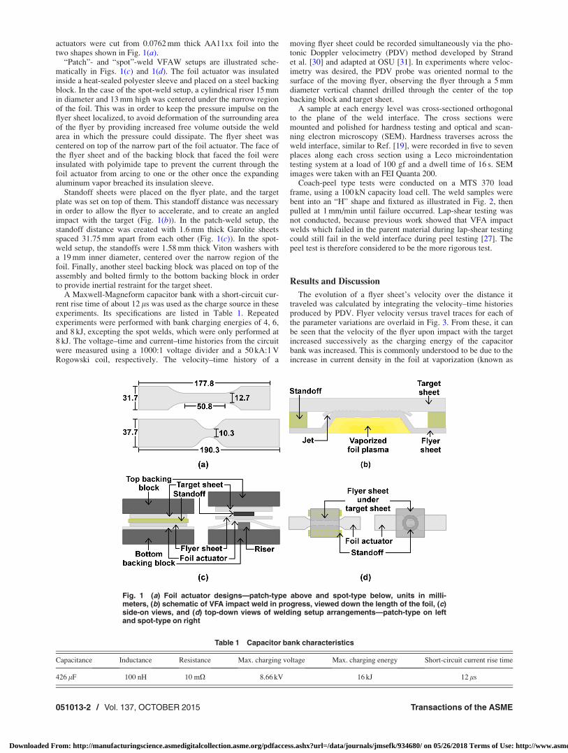
actuators were cut from 0.0762 mm thick AA11xx foil into thetwo shapes shown in Fig. 1(a).
“Patch”- and “spot”-weld VFAW setups are illustrated sche-matically in Figs. 1(c) and 1(d). The foil actuator was insulatedinside a heat-sealed polyester sleeve and placed on a steel backingblock. In the case of the spot-weld setup, a cylindrical riser 15 mmin diameter and 13 mm high was centered under the narrow regionof the foil. This was in order to keep the pressure impulse on theflyer sheet localized, to avoid deformation of the surrounding areaof the flyer by providing increased free volume outside the weldarea in which the pressure could dissipate. The flyer sheet wascentered on top of the narrow part of the foil actuator. The face ofthe flyer sheet and of the backing block that faced the foil wereinsulated with polyimide tape to prevent the current through thefoil actuator from arcing to one or the other once the expandingaluminum vapor breached its insulation sleeve.
Standoff sheets were placed on the flyer plate, and the targetplate was set on top of them. This standoff distance was necessaryin order to allow the flyer to accelerate, and to create an angledimpact with the target (Fig. 1(b)). In the patch-weld setup, thestandoff distance was created with 1.6 mm thick Garolite sheetsspaced 31.75 mm apart from each other (Fig. 1(c)). In the spot-weld setup, the standoffs were 1.58 mm thick Viton washers witha 19 mm inner diameter, centered over the narrow region of thefoil. Finally, another steel backing block was placed on top of theassembly and bolted firmly to the bottom backing block in orderto provide inertial restraint for the target sheet.
A Maxwell-Magneform capacitor bank with a short-circuit cur-rent rise time of about 12 ls was used as the charge source in theseexperiments. Its specifications are listed in Table 1. Repeatedexperiments were performed with bank charging energies of 4, 6,and 8 kJ, excepting the spot welds, which were only performed at8 kJ. The voltage–time and current–time histories from the circuitwere measured using a 1000:1 voltage divider and a 50 kA:1 VRogowski coil, respectively. The velocity–time history of a
moving flyer sheet could be recorded simultaneously via the pho-tonic Doppler velocimetry (PDV) method developed by Strandet al. [30] and adapted at OSU [31]. In experiments where veloc-imetry was desired, the PDV probe was oriented normal to thesurface of the moving flyer, observing the flyer through a 5 mmdiameter vertical channel drilled through the center of the topbacking block and target sheet.
A sample at each energy level was cross-sectioned orthogonalto the plane of the weld interface. The cross sections weremounted and polished for hardness testing and optical and scan-ning electron microscopy (SEM). Hardness traverses across theweld interface, similar to Ref. [19], were recorded in five to sevenplaces along each cross section using a Leco microindentationtesting system at a load of 100 gf and a dwell time of 16 s. SEMimages were taken with an FEI Quanta 200.
Coach-peel type tests were conducted on a MTS 370 loadframe, using a 100 kN capacity load cell. The weld samples werebent into an “H” shape and fixtured as illustrated in Fig. 2, thenpulled at 1 mm/min until failure occurred. Lap-shear testing wasnot conducted, because previous work showed that VFA impactwelds which failed in the parent material during lap-shear testingcould still fail in the weld interface during peel testing [27]. Thepeel test is therefore considered to be the more rigorous test.
Results and Discussion
The evolution of a flyer sheet’s velocity over the distance ittraveled was calculated by integrating the velocity–time historiesproduced by PDV. Flyer velocity versus travel traces for each ofthe parameter variations are overlaid in Fig. 3. From these, it canbe seen that the velocity of the flyer upon impact with the targetincreased successively as the charging energy of the capacitorbank was increased. This is commonly understood to be due to theincrease in current density in the foil at vaporization (known as
Fig. 1 (a) Foil actuator designs—patch-type above and spot-type below, units in milli-meters, (b) schematic of VFA impact weld in progress, viewed down the length of the foil, (c)side-on views, and (d) top-down views of welding setup arrangements—patch-type on leftand spot-type on right
Table 1 Capacitor bank characteristics
Capacitance Inductance Resistance Max. charging voltage Max. charging energy Short-circuit current rise time
426 lF 100 nH 10 mX 8.66 kV 16 kJ 12 ls
051013-2 / Vol. 137, OCTOBER 2015 Transactions of the ASME
Downloaded From: http://manufacturingscience.asmedigitalcollection.asme.org/pdfaccess.ashx?url=/data/journals/jmsefk/934680/ on 05/26/2018 Terms of Use: http://www.asme.org/about-asme/terms-of-use
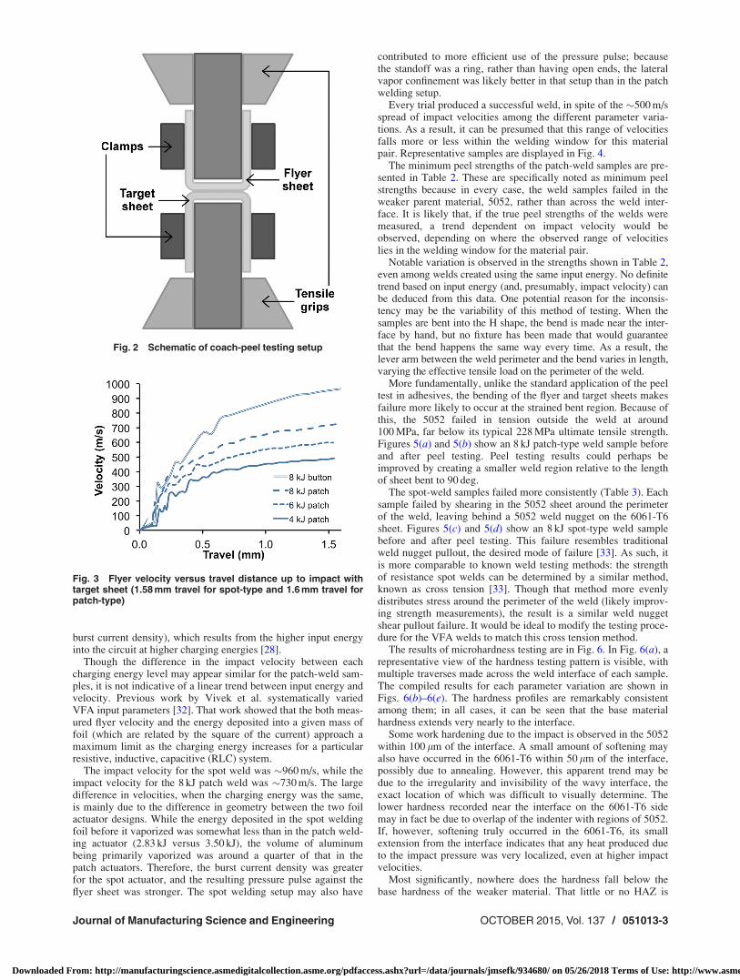
burst current density), which results from the higher input energyinto the circuit at higher charging energies [28].
Though the difference in the impact velocity between eachcharging energy level may appear similar for the patch-weld sam-ples, it is not indicative of a linear trend between input energy andvelocity. Previous work by Vivek et al. systematically variedVFA input parameters [32]. That work showed that the both meas-ured flyer velocity and the energy deposited into a given mass offoil (which are related by the square of the current) approach amaximum limit as the charging energy increases for a particularresistive, inductive, capacitive (RLC) system.
The impact velocity for the spot weld was �960 m/s, while theimpact velocity for the 8 kJ patch weld was �730 m/s. The largedifference in velocities, when the charging energy was the same,is mainly due to the difference in geometry between the two foilactuator designs. While the energy deposited in the spot weldingfoil before it vaporized was somewhat less than in the patch weld-ing actuator (2.83 kJ versus 3.50 kJ), the volume of aluminumbeing primarily vaporized was around a quarter of that in thepatch actuators. Therefore, the burst current density was greaterfor the spot actuator, and the resulting pressure pulse against theflyer sheet was stronger. The spot welding setup may also have
contributed to more efficient use of the pressure pulse; becausethe standoff was a ring, rather than having open ends, the lateralvapor confinement was likely better in that setup than in the patchwelding setup.
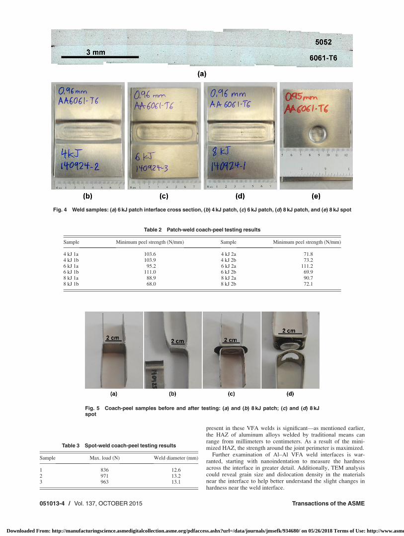
Every trial produced a successful weld, in spite of the �500 m/sspread of impact velocities among the different parameter varia-tions. As a result, it can be presumed that this range of velocitiesfalls more or less within the welding window for this materialpair. Representative samples are displayed in Fig. 4.
The minimum peel strengths of the patch-weld samples are pre-sented in Table 2. These are specifically noted as minimum peelstrengths because in every case, the weld samples failed in theweaker parent material, 5052, rather than across the weld inter-face. It is likely that, if the true peel strengths of the welds weremeasured, a trend dependent on impact velocity would beobserved, depending on where the observed range of velocitieslies in the welding window for the material pair.
Notable variation is observed in the strengths shown in Table 2,even among welds created using the same input energy. No definitetrend based on input energy (and, presumably, impact velocity) canbe deduced from this data. One potential reason for the inconsis-tency may be the variability of this method of testing. When thesamples are bent into the H shape, the bend is made near the inter-face by hand, but no fixture has been made that would guaranteethat the bend happens the same way every time. As a result, thelever arm between the weld perimeter and the bend varies in length,varying the effective tensile load on the perimeter of the weld.
More fundamentally, unlike the standard application of the peeltest in adhesives, the bending of the flyer and target sheets makesfailure more likely to occur at the strained bent region. Because ofthis, the 5052 failed in tension outside the weld at around100 MPa, far below its typical 228 MPa ultimate tensile strength.Figures 5(a) and 5(b) show an 8 kJ patch-type weld sample beforeand after peel testing. Peel testing results could perhaps beimproved by creating a smaller weld region relative to the lengthof sheet bent to 90 deg.
The spot-weld samples failed more consistently (Table 3). Eachsample failed by shearing in the 5052 sheet around the perimeterof the weld, leaving behind a 5052 weld nugget on the 6061-T6sheet. Figures 5(c) and 5(d) show an 8 kJ spot-type weld samplebefore and after peel testing. This failure resembles traditionalweld nugget pullout, the desired mode of failure [33]. As such, itis more comparable to known weld testing methods: the strengthof resistance spot welds can be determined by a similar method,known as cross tension [33]. Though that method more evenlydistributes stress around the perimeter of the weld (likely improv-ing strength measurements), the result is a similar weld nuggetshear pullout failure. It would be ideal to modify the testing proce-dure for the VFA welds to match this cross tension method.
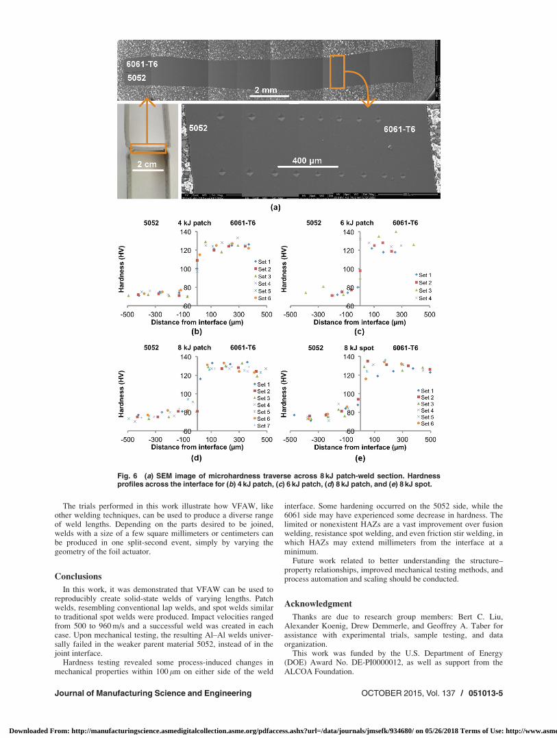
The results of microhardness testing are in Fig. 6. In Fig. 6(a), arepresentative view of the hardness testing pattern is visible, withmultiple traverses made across the weld interface of each sample.The compiled results for each parameter variation are shown inFigs. 6(b)–6(e). The hardness profiles are remarkably consistentamong them; in all cases, it can be seen that the base materialhardness extends very nearly to the interface.
Some work hardening due to the impact is observed in the 5052within 100 lm of the interface. A small amount of softening mayalso have occurred in the 6061-T6 within 50 lm of the interface,possibly due to annealing. However, this apparent trend may bedue to the irregularity and invisibility of the wavy interface, theexact location of which was difficult to visually determine. Thelower hardness recorded near the interface on the 6061-T6 sidemay in fact be due to overlap of the indenter with regions of 5052.If, however, softening truly occurred in the 6061-T6, its smallextension from the interface indicates that any heat produced dueto the impact pressure was very localized, even at higher impactvelocities.
Most significantly, nowhere does the hardness fall below thebase hardness of the weaker material. That little or no HAZ is
Fig. 3 Flyer velocity versus travel distance up to impact withtarget sheet (1.58 mm travel for spot-type and 1.6 mm travel forpatch-type)
Fig. 2 Schematic of coach-peel testing setup
Journal of Manufacturing Science and Engineering OCTOBER 2015, Vol. 137 / 051013-3
Downloaded From: http://manufacturingscience.asmedigitalcollection.asme.org/pdfaccess.ashx?url=/data/journals/jmsefk/934680/ on 05/26/2018 Terms of Use: http://www.asme.org/about-asme/terms-of-use
present in these VFA welds is significant—as mentioned earlier,the HAZ of aluminum alloys welded by traditional means canrange from millimeters to centimeters. As a result of the mini-mized HAZ, the strength around the joint perimeter is maximized.
Further examination of Al–Al VFA weld interfaces is war-ranted, starting with nanoindentation to measure the hardnessacross the interface in greater detail. Additionally, TEM analysiscould reveal grain size and dislocation density in the materialsnear the interface to help better understand the slight changes inhardness near the weld interface.
Table 2 Patch-weld coach-peel testing results
Sample Minimum peel strength (N/mm) Sample Minimum peel strength (N/mm)
4 kJ 1a 103.6 4 kJ 2a 71.84 kJ 1b 103.9 4 kJ 2b 73.26 kJ 1a 95.2 6 kJ 2a 111.26 kJ 1b 111.0 6 kJ 2b 69.98 kJ 1a 88.9 8 kJ 2a 90.78 kJ 1b 68.0 8 kJ 2b 72.1
Fig. 5 Coach-peel samples before and after testing: (a) and (b) 8 kJ patch; (c) and (d) 8 kJspot
Table 3 Spot-weld coach-peel testing results
Sample Max. load (N) Weld diameter (mm)
1 836 12.62 971 13.23 963 13.1
Fig. 4 Weld samples: (a) 6 kJ patch interface cross section, (b) 4 kJ patch, (c) 6 kJ patch, (d) 8 kJ patch, and (e) 8 kJ spot
051013-4 / Vol. 137, OCTOBER 2015 Transactions of the ASME
Downloaded From: http://manufacturingscience.asmedigitalcollection.asme.org/pdfaccess.ashx?url=/data/journals/jmsefk/934680/ on 05/26/2018 Terms of Use: http://www.asme.org/about-asme/terms-of-use
The trials performed in this work illustrate how VFAW, likeother welding techniques, can be used to produce a diverse rangeof weld lengths. Depending on the parts desired to be joined,welds with a size of a few square millimeters or centimeters canbe produced in one split-second event, simply by varying thegeometry of the foil actuator.
Conclusions
In this work, it was demonstrated that VFAW can be used toreproducibly create solid-state welds of varying lengths. Patchwelds, resembling conventional lap welds, and spot welds similarto traditional spot welds were produced. Impact velocities rangedfrom 500 to 960 m/s and a successful weld was created in eachcase. Upon mechanical testing, the resulting Al–Al welds univer-sally failed in the weaker parent material 5052, instead of in thejoint interface.
Hardness testing revealed some process-induced changes inmechanical properties within 100 lm on either side of the weld
interface. Some hardening occurred on the 5052 side, while the6061 side may have experienced some decrease in hardness. Thelimited or nonexistent HAZs are a vast improvement over fusionwelding, resistance spot welding, and even friction stir welding, inwhich HAZs may extend millimeters from the interface at aminimum.
Future work related to better understanding the structure–property relationships, improved mechanical testing methods, andprocess automation and scaling should be conducted.
Acknowledgment
Thanks are due to research group members: Bert C. Liu,Alexander Koenig, Drew Demmerle, and Geoffrey A. Taber forassistance with experimental trials, sample testing, and dataorganization.
This work was funded by the U.S. Department of Energy(DOE) Award No. DE-PI0000012, as well as support from theALCOA Foundation.
Fig. 6 (a) SEM image of microhardness traverse across 8 kJ patch-weld section. Hardnessprofiles across the interface for (b) 4 kJ patch, (c) 6 kJ patch, (d) 8 kJ patch, and (e) 8 kJ spot.
Journal of Manufacturing Science and Engineering OCTOBER 2015, Vol. 137 / 051013-5
Downloaded From: http://manufacturingscience.asmedigitalcollection.asme.org/pdfaccess.ashx?url=/data/journals/jmsefk/934680/ on 05/26/2018 Terms of Use: http://www.asme.org/about-asme/terms-of-use
Nomenclature
EM ¼ electromagneticEXW ¼ explosive welding
gf ¼ gram-force, a nonstandard gravitational metric unitcommonly used for hardness testing loads
HAZ ¼ heat-affected zone(s)HV ¼ Vickers pyramid number, a unit of hardness
MPW ¼ magnetic pulse weldingPDV ¼ photonic Doppler velocimetryRLC ¼ resistive, inductive, capacitive, in reference to an elec-
trical circuitVFA ¼ vaporizing foil actuator(s)
VFAW ¼ vaporizing foil actuator welding
References[1] Zhou, C., Yang, X., and Luan, G., 2006, “Effect of Root Flaws on the Fatigue
Property of Friction Stir Welds in 2024-T3 Aluminum Alloys,” Mater. Sci.Eng., A, 418(1–2), pp. 155–160.
[2] Aleo, V., Madugula, M. K. S., and Balachandar, R., 2006, “Development of anEquation for Aluminum Alloys to Determine the Width of the Zone Affectedby Welding,” Can. J. Civ. Eng., 33(2), pp. 151–160.
[3] Mallick, P. K., 2010, “Overview,” Materials, Design and Manufacturing forLightweight Vehicles, P. K. Mallick, ed., Woodhead Publishing Limited, Cam-bridge, UK, pp. 1–32.
[4] Ambriz, R. R., and Mayagoitia, V., 2011, “Welding of Aluminum Alloys,”Recent Trends in Processing and Degradation of Aluminium Alloys, Z. Ahmad,ed., InTech, Rijeka, Croatia, pp. 63–86.
[5] Cao, R., Sun, J. H., Chen, J. H., and Wang, P.-C., 2014, “Cold Metal TransferJoining of Aluminum AA6061-T6-to-Galvanized Boron Steel,” ASME J.Manuf. Sci. Eng., 136(5), p. 051015.
[6] Yuan, W., Mishra, R. S., Webb, S., Chen, Y. L., Carlson, B., Herling, D. R.,and Grant, G. J., 2011, “Effect of Tool Design and Process Parameters on Prop-erties of Al Alloy 6016 Friction Stir Spot Welds,” J. Mater. Process. Technol.,211(6), pp. 972–977.
[7] Mathers, G., 2002, “Welding Metallurgy,” The Welding of Aluminium and ItsAlloys, Woodhead Publishing Limited, Cambridge, UK, pp. 10–34.
[8] Merriman, C., 2006, “The Fundamentals of Explosion Welding,” Weld. J.,85(7), pp. 27–29.
[9] Patterson, R. A., 1993, “Fundamentals of Explosion Welding,” ASM Handbook(Welding, Brazing, and Soldering, Vol. 06), D. L. Olson, T. A. Siewert, S. Liu,and G. R. Edwards eds., ASM International, Materials Park, OH, pp. 160–164.
[10] Cowan, G. R., Bergmann, O. R., and Holtzmann, A. H., 1971, “Mechanism ofBond Zone Wave Formation in Explosion-Clad Metals,” Metall. Mater. Trans.B, 2(11), pp. 3145–3155.
[11] Durgutlu, A., G€ulenc, B., and Findik, F., 2005, “Examination of Copper/StainlessSteel Joints Formed by Explosive Welding,” Mater. Des., 26(6), pp. 497–507.
[12] Wu, X., and Shang, J., 2014, “An Investigation of Magnetic Pulse Welding of Al/Cu and Interface Characterization,” ASME J. Manuf. Sci. Eng., 136(5), p. 051002.
[13] Grignon, F., Benson, D., Vecchio, K. S., and Meyers, M. A., 2004, “ExplosiveWelding of Aluminum to Aluminum: Analysis, Computations andExperiments,” Int. J. Impact Eng., 30(10), pp. 1333–1351.
[14] Raoelison, R. N., Buiron, N., Rachik, M., Haye, D., Franz, G., and Habak, M.,2013, “Study of the Elaboration of a Practical Weldability Window in MagneticPulse Welding,” J. Mater. Process. Technol., 213(8), pp. 1348–1354.
[15] Ben-Artzy, A., Stern, A., Frage, N., Shribman, V., and Sadot, O., 2010, “WaveFormation Mechanism in Magnetic Pulse Welding,” Int. J. Impact Eng., 37(4),pp. 397–404.
[16] Nassiri, A., Chini, G., and Kinsey, B., 2014, “Spatial Stability Analysisof Emergent Wavy Interfacial Patterns in Magnetic Pulsed Welding,” CIRPAnn.-Manuf. Technol., 63(1), pp. 245–248.
[17] Cooper, P., 1996, “Real Effects in Explosives,” Explosives Engineering, Wiley,New York, pp. 275–297.
[18] Sch€afer, R., Pasquale, P., and Elsen, A., 2011, “Material Hybrid Joining ofSheet Metals by Electromagnetic Pulse Technology,” Key Eng. Mater., 473, pp.61–68.
[19] Shribman, V., Stern, A., Livshitz, Y., and Gafri, O., 2002, “Magnetic Pulse Weld-ing Produces High-Strength Aluminum Welds,” Weld. J., 81(4), pp. 33–37.
[20] Okagawa, K., and Aizawa, T., 2004, “Impact Seam Welding With MagneticPressure for Aluminum Sheets,” Mater. Sci. Forum, 465–466, pp. 231–236.
[21] Kore, S. D., Date, P. P., and Kulkarni, S. V., 2007, “Effect of Process Parame-ters on Electromagnetic Impact Welding of Aluminum Sheets,” Int. J. ImpactEng., 34(8), pp. 1327–1341.
[22] Kore, S. D., Date, P. P., Kulkarni, S. V., Kumar, S., Kulkarni, M. R., Desai, S.V., Rajawat, R. K., Nagesh, K. V., and Chakravarty, D. P., 2009,“Electromagnetic Impact Welding of Al-to-Al–Li Sheets,” ASME J. Manuf.Sci. Eng., 131(3), p. 034502.
[23] Weddeling, C., Hahn, M., Daehn, G. S., and Tekkaya, A. E., 2014, “UniformPressure Electromagnetic Actuator—An Innovative Tool for Magnetic PulseWelding,” Procedia CIRP, 18, pp. 156–161.
[24] Watanabe, M., and Kumai, S., 2009, “High-Speed Deformation and CollisionBehavior of Pure Aluminum Plates in Magnetic Pulse Welding,” J. Jpn. Inst.Light Met., 59(9), pp. 502–508.
[25] Golovashchenko, S. F., 2007, “Material Formability and Coil Design in Electro-magnetic Forming,” J. Mater. Eng. Perform., 16(3), pp. 314–320.
[26] Daehn, G. S., 2006, “High Velocity Metal Forming,” ASM Handbook (Metal-working: Sheet Forming, Vol. 14B), S. L. Semiatin, ed., ASM International,Materials Park, OH, pp. 405–418.
[27] Vivek, A., Hansen, S. R., Liu, B. C., and Daehn, G. S., 2013, “Vaporizing FoilActuator: A Tool for Collision Welding,” J. Mater. Process. Technol., 213(12),pp. 2304–2311.
[28] Chau, H. H., Dittbenner, G., Hofer, W. W., Honodel, C. A., and Steinberg, D.J., 1980, “Electric Gun: A Versatile Tool for High Pressure ShockwaveResearch,” Rev. Sci. Instrum., 51(12), pp. 1676–1681.
[29] Vivek, A., Brune, R. C., Hansen, S. R., and Daehn, G. S., 2014, “VaporizingFoil Actuator Used for Impulse Forming and Embossing of Titanium and Alu-minum Alloys,” J. Mater. Process. Technol., 214(4), pp. 865–875.
[30] Strand, O. T., Goosman, D. R., Martinez, C., Whitworth, T. L., and Kuhlow,W. W., 2006, “Compact System for High-Speed Velocimetry Using HeterodyneTechniques,” Rev. Sci. Instrum., 77(8), p. 083108.
[31] Johnson, J. R., Taber, G., Vivek, A., Zhang, Y., Banik, K., Fenton, G. K., andDaehn, G. S., 2009, “Coupling Experiment and Simulation in ElectromagneticForming Using Photon Doppler Velocimetry,” Steel Res. Int., 80(5), pp. 359–365.
[32] Vivek, A., Hansen, S. R., and Daehn, G. S., 2014, “High Strain Rate Metal-working With Vaporizing Foil Actuator: Control of Flyer Velocity by VaryingInput Energy and Foil Thickness,” Rev. Sci. Instrum., 85(7), p. 075101.
[33] Chao, Y. J., 2003, “Ultimate Strength and Failure Mechanism of ResistanceSpot Weld Subjected to Tensile, Shear, or Combined Tensile/Shear Loads,”ASME J. Eng. Mater. Technol., 125(2), pp. 125–132.
051013-6 / Vol. 137, OCTOBER 2015 Transactions of the ASME
Downloaded From: http://manufacturingscience.asmedigitalcollection.asme.org/pdfaccess.ashx?url=/data/journals/jmsefk/934680/ on 05/26/2018 Terms of Use: http://www.asme.org/about-asme/terms-of-use