Embed Size (px)
Citation preview

Sterisil® System Bottle FillInstallation & Operating Manual
719 622 7200 Sterisil.com

719 622 7200 Sterisil.com
Safe, Simple, Sterisil

Table of Contents
Introduction 1
Sterisil® System Features 2
Special Notices & Reminders 3
Installation Part Checklist 4
Sterisil® System Specifications 5
Installation Details 6
Installation Instructions 7-17
Operational Test 18-19
Sterisil® System Diagram 20
Monitor Information and Summary 21-22
Replacing Filter Cartridges & UV Light 23-24
Sterisil® System Data Log Sheet 25
Setting up Filter Monitor 26
Battery Replacement for Monitors 27-28
Sterisil® System Troubleshooting 29-30
Monitor Reset Instructions 31-38
Frequently Asked Questions 39-40
Thank you 41

Pg. 1
Introduction
The Sterisil® System requires no tablets or additional additives for daily dental water use. This System uses six stages of treatment, including Class B Ultraviolet Irradiation disinfection of many microorganisms such as Pseudomonas, Streptococcus, Legionella and Mycobacterium Tuberculosis.
The Sterisil System is EPA registered to produce treated dental water, autoclave water and final rinse water. The system is capable of providing treated dental water for any size office, 1 to 100+ chairs. The treated dental water is EPA registered and is backed by a quantified claim of ~≤10CFU/ml, that's 50 times lower than the ADA and CDC guidelines. The dental water is further conditioned to remove acidity with Sterisil’s silver impregnated resin. This stage of treatment also provides stabilized silver to maintain and regenerate silver based antimicrobial dental tubing.
The Sterisil water purification system produces distilled quality water to 0ppm TDS for table top autoclaves. It continuously purifies autoclave and dental water from source water contaminants and disinfects the water using ultraviolet (UV) light irradiation.
The system also creates final rinse water for the final rinse cycle on instrument washers. A bladder tank is included with the Sterisil System to provide on-demand water for all of your final rinse water needs.
This Sterisil® System uses seven stages of treatment with ANSI/NSF Standards 42 (taste and odor), 55-Class B (UV Systems) and 58 (reverse osmosis) components to produce ultra pure water. Virtually all of the water contaminates are eliminated. This includes removing 99% of over 34 inorganic contaminates such as arsenic, lead, mercury, chromium, nitrate and chloride.
The Sterisil® System reduces organic compounds such as benzene, trichloroethane, trihalomethanes, PCE MTBE. Protozoan parasites such as Giardia and Cryptosporidium are essentially eliminated through hyper filtration. The UV irradiation dose is 16.7 mJ/cm2, producing a lethal dose capable of up to 5 Log reduction of many microorganisms including species of Pseudomonas, Streptococcus, Salmonella, Escherichia coli, Staphylococcus, Legionella and Mycobacterium tuberculosis.
Pg. 2
Sterisil® System Features
Simple + Produces distilled quality autoclave water and up to 10 years of dental water. + 6 stages of purification treatment. + Compact design to fit in a Sterilization Center typical sink cabinet. Slide mounted to allow for easy access to the Unit. + Simple cartridge replacement with automatic shut-off valves to prevent water spillage. + Optional dental water cartridge selection for a range of 4 to 100+ dental units.
Safe + Dental water is non-toxic and safe for patients and clinicians. + Treated dental water does not affect composite bonding. + Meets Best Management Practices (BMP) for dental waste water, contains no oxidizers, and does not dissolve amalgam. + Non-corrosive and safe for patients, staff, and dental equipment. + Damage protection enclosure for tubing and fittings. + Maintains antimicrobial dental tubing.
Effective + Water quality monitoring + Autoclave water quality monitoring with fail-safe visual and audible alarms. + Dental water capacity monitoring with fail-safe visual and audible alarms to determine when to replace cartridges. + Dispensing faucets with LED monitoring lights. + All tubing and fittings have been concealed to prevent accidental damage resulting in potential water leaks. + Hinged or sliding brackets available to allow easy access to the Unit.
Regulatory Clearances + FDA 510(k) cleared + CRA recommended + ISO 13485 certified and CE certified + EPA Establishment No.: 83315-CO-001 + EPA Registration No. for Residual Disinfection: 83315-2

Pg. 3
Special Notices, Warnings & Reminders
1. Please read the complete Installation Manual thoroughly before starting the installation to understand maintenance, capabilities, and limitations of the system.
2. Please refer to all the drawings in this document for references as you install your Sterisil® System. We strongly recommend the installation be done by a trained service tech or plumber who is familiar with water systems.
3. Make sure to record your Sterisil® System serial number found on left side of the Sterisil® System.
4. Be certain that all staff involved in the annual maintenance of the Sterisil® System fully understand the Sterisil® System.
5. Perform the Citrisil Shock Instructions on the initial install of the Sterisil® System.
6. Please return the Warranty / Registration form or register online immediately upon installation.
7. PLEASE READ EACH INSTALLATION STEP CAREFULLY AND KEEP THIS INSTALLATION MANUAL WITH YOUR PERMANENT RECORDS.

Pg. 4
Sterisil System Parts
Reserve (L) & Dental (R) Water Bladder Tanks w/Valves
Sterisil System Back View w/ Slides (L) & Hinges (R) Options
plus Electrical Connections
UV Lamp Transformer
(Black)
Mounting Bracket (L) & Blank Cartridge (R)
Sterisil System Cartridges w/1,000L Stage 5 Cartridge
Supply Extender Tee Autoclave Water Faucet (White, L) w/ LED Disc (C) & Data Wire
w/ Modular Coupler (R)
Tees: 1/4” (1,T) Reducer: 1/2” » 1/4”
System Tubing: 1/4” (L) & 3/8” (R)
Bag Containing: Manual, Packing List, Faucet Stickers, Tank
Stickers and Warranty Card
Mounting Bracket (L) & Permeate Pump (R)
Citrisil Shock (Number of boxes will vary)
Drain Saddle Valve Flow Sensor w/ Data Wire, Modular
Coupler & Female Connector
Booster Pump Optional (L) & Transformer (R)
Pressure Gauge 1/4” kit (2) 3/8” kit (1)
Pre-assembled
Pre Filter Kit Optional (L) & Bracket (R)
Dental Water Faucet (Chrome, L) w/ LED Disc (C) & Data Wire
w/ Modular Coupler (R)
CitirisilAll in One Maintenance Tablet

Pg. 5
System Specifications
STERISIL SYSTEM
17- 5/8”
17- 3/16” 17- 3/16”
5- 1/2”
6- 7/8”
System Bottle Fill SpecificationsMinimum Pressure 65 PSIMaximum Pressure 125 PSIMinimum Temperature 45°FMaximum Temperature 100°FFaucets (2) Sink with space for two faucetsPlumbing System Bypass N/APlumbing Drain Standard sink or floor drainElectrical Outlets (1) Quad outlet 110V AC, 3 amp, GFCI, within 3' from SystemMounting Space System: 19"W x 18"H x 7"DBladder Tank Space Tank 2G: 12"H x 9"Dia
Tank 4G: 15"H x 12"DiaTank 10G: 21"H x 13"DiaTank 14G: 23"H x 15.25"Dia
Pre-Filter Kit Space (Optional) 12"H x 4"WBooster Pump Space (Optional) 4.5H x 4.5"W

Pg. 6
Installation Details
UNPACKINGCarefully unpack the contents of the boxes. One box will include the Sterisil® System, Installation Manual, Warranty Registration Card, large bag, small bag, a drain saddle valve, Shock Cartridge, a white table top faucet, push-in connect fittings, 1/4" tubing, 3/8" tubing, etc. The second box will include two bladder tanks.
Check to make certain there was no damage during shipment. If damage is evident, contact the shipping company immediately.
TOOLSRequired tools vary but typically include a sharp razor knife or tube cutter, measuring tape, drill, assorted bits and screws, screwdrivers, wrenches, level, and clean rags.
LOCATIONGenerally the System is installed centrally within the dental office. It is normally installed in the equipment room, sterilization center, hallway, or laboratory. If hinged bracket is selected, the typical mounting location is on the wall near a source water supply. If sliding is bracket selected, the typical mounting location is under a sink near a source water supply.
TUBING & CONNECTIONSCopper tubing is not to be used to transport the water from the Sterisil System to each individual chair or to the remote dispensing station. However, copper piping may be used from the source water to the System itself. Make sure cuts on the tubing are square and clean to prevent leaks.

Pg. 7
Installation Instructions
1. Familiarize yourself with the System connections by reviewing the complete System diagram on page 20.
2. Prep Installation Sitea. Remove items under sink and away from wall mount site to facilitate installation.b. Ensure (3) 110V AC electrical outlets are available at site as well as serviceable municipal supply and drain.
3. Remove mounting plate from unit and test fit at desired location. NOTE: For cabinet mount, ensure room for tubing and wiring behind Unit and 19” of vertical clearance for Filter Cartridge installation and removal (see installation diagram below).
4. Place mounting plate in desired location using level (mounting hardware supplied).
Mounting Plate(Back View)
Screws & Anchors for Wall-Mounting

Pg. 8
Installation Instructions5. For counter top Faucet installation (Option 1), drill a 5/8” hole, ensuring holes are on sink
surface at desired location and the LED data wires fit without pinching during installation. For remote bracket installation (Option 2), select convenient wall location and mount via screws and anchors provided.
NOTE: White faucet is for Autoclave Water, Chrome faucet is for Dental Water.
6. Tighten Faucet in place and install Quick Connect Fitting (supplied with Faucet).
LED
Data Wire
Option 1: Counter Top Mount displaying 5/8” Hole
(Counter Thickness Varies)
Remote Bracket
Option 2: Remote Bracket displaying Screws & Anchors
Faucet Alarm (optional)
Washer
Lock Washer
Quick Connect Fitting
Plastic Gasket
Nut

Pg. 9
Installation Instructions7. Slide Sterisil® System onto Mounting Plate slides, allowing hinges to lock. Test for fit and
operation. Leave in extended position to facilitate proper fitting of tubing/electrical/data wires.
8. Establish and locate Sterisil® System plumbing connections.
Sterisil System (Left Side View)

Pg. 10
Installation Instructions9. Establish Sterisil® System plumbing connections. (Cont’d)...
a. Between Municipal Water Supply and Sterisil® System Source Line tubing:NOTE: If separate water source is not provided, shut off water supply and install EasyConnector and onto existing Cold Water Supply Valve.
b. OPTIONAL - Install Booster Pump and/or Pre-Filter Kit onto 1/4" Source Water Line
Municipal Coldwater Supply
Source WaterLine
Source Water‘Off’ Position
STERISIL SYSTEM
Sink Water Supply
Easy Connector & Ball Valve Assembly w/ Cold Water Supply Valve
Source Water‘On’ Position
SINK WATER SUPPLY
MUNICIPAL COLDWATER
FEED
Booster Pump
Pre-Filter

Pg. 11
Installation Instructionsc. Between 1/4” Source Water tubing Unit Source Input (red cap), insert Pressure Gauge.
Leave enough tubing to allow Unit to slide out of cabinet for maintenance.
10. Install Sterisil® System Filter Cartridges.a. With Unit extended and/or rotated at hinges, begin installation starting with Stage 1
Cartridge.
d. Install included Blank Cartridge in cabinet or on wall close to unit.
Blank CartridgeMounting Bracket w/ Mounting Hardware
STERISIL® SYSTEM
1/4” Source Water Tubing
Pg. 12
Installation Instructions11. While installing Stage 3 R/O Filter, ensure plug is removed from bottom of filter. Mount the
Permeate Pump with bracket in the desired location. Route R/O filter drain line tubing to "BRINE IN" port on Permeate Pump.
12. Establish 1/4" PEX tubing connections between "BRINE OUT" port on Permeate Pump and 1/4" saddle valve on sink drain OR designated floor drain OR other usable drain.
a. If draining the Sterisil System into the sink, install the Drain Saddle Valve. 1. Mark location on pipe for 1/4” hole.2. Drill 1/4” hole. 3. Place and center gasket over 1/4” hole. 4. Place and secure Drain Saddle Valve over gasket. 5. Tighten Saddle Valve in proper position over hole and gasket. 6. Insert tubing into valve.
PERMEATEOUT
BRINE INBRINE OUT
PERMEATE IN
STERISIL® SYSTEM

Pg. 13
Installation Instructions
15. Complete installation of Stage 4's and Stage 5 Cartridges.
All Filter Cartridges Installed
13. Establish 1/4" PEX tubing connections between "PERMEATE IN" port on Permeate Pump and "PERMEATE IN" outlet (black cap) on the left side of the Sterisil System.
14. Establish 1/4" PEX tubing connections between "PERMEATE OUT" port on the Permeate Pump to the "PERMEATE OUT" outlet (grey cap) on the left side of the Sterisil® System.
PERMEATEOUT
BRINE INBRINE OUT
PERMEATE IN
STERISIL SYSTEM
Pg. 14
Installation Instructions
17. Install 3/8" Reserve and 1/4" Dental Water Bladder Tank Valves.
3/8” Valve installed onto 4-Gallon Bladder Tank
1/4” Valve installed onto 2-Gallon Bladder Tank
16. Connect 1/4" tubing from Autoclave Water Port (green cap) to Autoclave Water Faucet. Leave room for maintenance of Unit.
NOTE: Tank sizes will vary depending on Stage 5 selection or pre install requirements.
1/4” LINE
STERISIL® SYSTEM

Pg. 15
Installation Instructions
19. Connect 1/4" tubing from Dental Water Port (blue cap) to 1/4" tee. a. Connect 1/4" tubing between 1/4" tee to 1/4" dental water bladder tank valve while
installing a Pressure Gauge along 1/4" tubing between connections. Leave room for maintenance.
18. Establish 3/8"" PEX tubing connection between tank ball valve to Pressure Gauge. a. Route 3/8" PEX tubing from the Pressure Gauge to the "RESERVE" port (yellow cap).
RESERVEWATER
STERISIL® SYSTEM3/8” LINE
15”
12”
DENTAL WATER
STERISIL® SYSTEMPressure
Gauge

Pg. 16
Installation Instructionsb. Connect 1/4” tubing between 1/4” tee and included Flow Meter.c. Connect Flow Meter data cable to Flow Meter data cable using the modular coupler. d. Route 1/4" tubing between Flow Meter to Dental Water faucet.
NOTE: Ensure Dental Water Supply valve is in closed/off position. Customer-supplied orOPTIONAL Sterisil® Check Valve MUST be installed to prevent back flow in system lines.
DENTAL WATER
STERISI®L SYSTEM
Modular
Coupler FlowMeter
Dental Faucet (Chrome)
Pressure
Gauge

Pg. 17
Installation Instructions20. Connect all flat, 4-wire data standard power cords using color code and labels attached to
wires. Note: Wiring for optional remote data monitoring provided upon request.
If Sterisil® System is mounted using slides, then slide unit in and out to ensure there is no binding or pinching of wires and tubing.
Autoclave Modular Coupler
Flow Meter Modular Coupler
Sterisil® SystemPower Cord
UV Lamp Power Cord and
Transformer (black)
Dental Modular Coupler

Pg. 18
Operational Test1. Before connecting power to various system components, open Source Water Valve and allow
Sterisil® System lines to fill with Bladder Tank Valves in closed position (valve handle is at 90 degrees to tubing inlet).
NOTE: As Filters fill, R/O drain line will flow as Sterisil® System removes contaminants and flushes them to drain.
Using the autoclave faucet on the sink to remove air trapped in Sterisil® System, bleed the system. NOTE: As you open Dental Water Faucet, you will notice light flashing ‘green’ to display ‘Good’ or ‘Acceptable’ condition of Dental water. It is designed to flash ‘yellow’ when Residual Disinfectant Cartridge is at 90% of depletion and to flash ‘red’ when Residual Disinfectant Cartridge should be changed out.
2. Please note readings from monitors on face of Unit: a. Source Water____________________ b. R/O____________________________ c. DI 1_____________________________ d. DI 2____________________________ e. FM 2____________________________
Bladder Tank Valve in ‘Closed’ Position
Bladder Tank Valve in ‘Open’ Position
FM-2 Source & RO
DI 1 & DI 2

Pg. 19
Operational Test4. Plug in all Electrical Power cords. NOTE: UV Lamp on end of Unit illuminates with dim color when connected properly.
5. After Sterisil® System lines are filled and pressurized, open valves to Bladder Tanks and fill. Depending upon water pressure and volume of Bladder Tanks. This will take approximately 4-8 hours.
UV Lamp & Plug Connect UV
Lamp Plug to System Input
Pg. 20
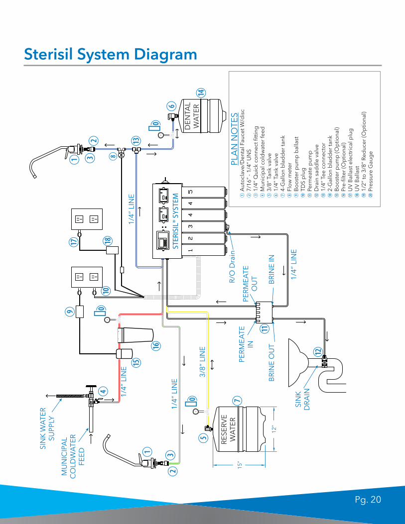
Sterisil System Diagram
RES
ERV
EW
ATE
R
DEN
TAL
WA
TER
STER
ISIL
® SY
STEM
SIN
K W
ATE
R
SUPP
LY
MU
NIC
IPA
L C
OLD
WA
TER
FE
ED
R/O
Dra
in
1/4”
LIN
E
3/8”
LIN
E
1/4”
LIN
E1/
4” L
INE
1/4”
LIN
E
PER
MEA
TE
OU
T
PER
MEA
TE
IN
BR
INE
INB
RIN
E O
UT
SIN
KD
RA
IN
PLA
N N
OTE
S15
”
12”
�
�
�
Pg. 21
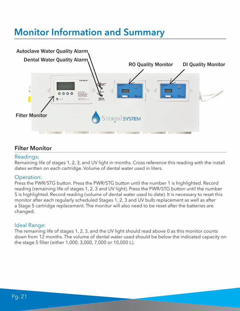
Monitor Information and Summary
Filter Monitor
RO Quality Monitor DI Quality Monitor
Autoclave Water Quality AlarmDental Water Quality Alarm
Filter MonitorReadings:Remaining life of stages 1, 2, 3, and UV light in months. Cross reference this reading with the install dates written on each cartridge. Volume of dental water used in liters.
Ideal Range:The remaining life of stages 1, 2, 3, and the UV light should read above 0 as this monitor counts down from 12 months. The volume of dental water used should be below the indicated capacity on the stage 5 filter (either 1,000, 3,000, 7,000 or 10,000 L).
Operation:Press the PWR/STG button. Press the PWR/STG button until the number 1 is highlighted. Record reading (remaining life of stages 1, 2, 3 and UV light). Press the PWR/STG button until the number 5 is highlighted. Record reading (volume of dental water used to date). It is necessary to reset this monitor after each regularly scheduled Stages 1, 2, 3 and UV bulb replacement as well as after a Stage 5 cartridge replacement. The monitor will also need to be reset after the batteries are changed.

Pg. 22
DI Quality Monitor
Monitor Information and Summary Cont'd
RO Quality Monitor
DI Quality Monitor
Readings:Water quality in parts per million Total Dissolved Solids (ppm TDS) of source water and RO water (Stage 3 cartridge).
Readings:Water quality in ppm TDS of the first and second Stage 4 cartridges.
Ideal Range:The RO reading should be 10% or less of the source water reading (example: if source is 150, RO should be 15 or less). If RO exceeds 10% of the source water reading, refer to Sterisil® System User Instructions under “RO reading is greater than 10% of my source reading.”
Ideal Range:DI1 should be less than 10 ppm TDS. The autoclave water quality alarm will turn red and the system will beep when 10 ppm is exceeded. DI2 will normally be below about 6 ppm TDS. Refer to your table top autoclave user’s manual to find the maximum allowable TDS that it will accept. This is the maximum allowable reading for DI2.
Operation:Press the On/Off button in the upper right of the monitor. Slide the white slide to the left. Record reading (Source water quality). Slide the white slide to the right. Record reading (RO water quality).Source water quality reading is dependent upon the systems location. It is normal for this reading to vary greatly as the readings are being taken.
Operation:Press the On/Off button in the upper right hand corner of the monitor. Slide the white slide to the left. Record reading (DI1 water quality). Slide the white slide to the right. Record reading (DI2 water quality).

Pg. 23
Replacing Filter Cartridges & UV Light
10 Minute Annual Change-Out
HOW TO REPLACE CARTRIDGES
To take out the cartridge, simply unscrew each cartridge as you would a light bulb. Flow of water will stop automatically in the valved-cartridge head. In the case of water spillage from the top, please keep a towel close by when replacing cartridges.
Replacing Stages 1, 2 & 3
Replace cartridges annually. Unscrew all Stages (1, 2, 3) before installing new cartridges.
Step 1: Unscrew Stage 1 cartridge. Step 2: Unscrew Stage 2 cartridge. Step 3: First, remove drain tube from the bottom of the Stage 3 cartridge. Push in on the collate and carefully pull out on the drain line. Note: Some water may run out of the bottom of the cartridge. Second, unscrew cartridge. Step 4: Dispose cartridges into regular trash disposal. Step 5: From right to left, install the correctly labeled cartridge in the desired position. Remember to insert drain line back into stage 3.
Replacing Stage 4 Cartridges
Replace cartridges when Autoclave Water Quality LED signals red and gives an audible alarm.
Step 1: From Slot 1, unscrew and throw away Stage 4. Step 2: Take out Stage 4 in Slot 2 and insert into Slot 1. Step 3: Insert new Stage 4 into Slot 2. Step 4: Make sure to write down installation date on the newly installed cartridge.
Drain Line Collate
Slot 1 Slot 2
IMPORTANT: Write down the installation date on the newly installed cartridge label.
NOTE: The Autoclave Water Quality alarm will reset automatically.

Pg. 24
Replacing the UV Light
Step 1: Unplug light from unit. Please do not look into the light when on as the ultraviolet light can cause eye damage.
Step 2: Use a flat head screw driver to pry out the white/clear piece. Dispose of UV light into trash disposal or use Sterisil’s recycling program.
Step 3: Insert new lamp and click into place. IMPORTANT: Do not touch the bulb. Grease from hands can cause damage to the lamp.
Replacing Stage 5 Cartridge
Replace cartridge when Dental Water Quality LED signals red and gives an audible alarm.
Step 1: Unscrew Stage 5 cartridge.
Step 2: Insert correctly labeled cartridge. Make sure part numbers match.
Step 3: Reset Stage 5 reading on the white Filter Monitor. Read the Monitor Reset Instructions to properly reset the monitor.
NOTE: After installing the new Stage 1, 2, 3 cartridges and UV light, please read the Monitor Reset Instructions to properly reset the Filter Monitor.

Pg. 25
Sterisil® System Data Log Sheet
Filters Installed on
DateSample Date
Source Water TDS (ppm)
Reverse Osmosis TDS
(ppm)
DI 1 TDS (ppm)
DI 2 TDS (ppm)
Pg. 26
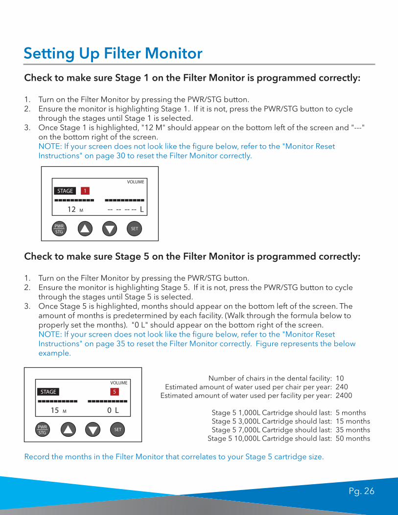
Setting Up Filter MonitorCheck to make sure Stage 1 on the Filter Monitor is programmed correctly:
1. Turn on the Filter Monitor by pressing the PWR/STG button. 2. Ensure the monitor is highlighting Stage 1. If it is not, press the PWR/STG button to cycle
through the stages until Stage 1 is selected. 3. Once Stage 1 is highlighted, "12 M" should appear on the bottom left of the screen and "---"
on the bottom right of the screen. NOTE: If your screen does not look like the figure below, refer to the "Monitor Reset Instructions" on page 30 to reset the Filter Monitor correctly.
Check to make sure Stage 5 on the Filter Monitor is programmed correctly:
1. Turn on the Filter Monitor by pressing the PWR/STG button. 2. Ensure the monitor is highlighting Stage 5. If it is not, press the PWR/STG button to cycle
through the stages until Stage 5 is selected. 3. Once Stage 5 is highlighted, months should appear on the bottom left of the screen. The
amount of months is predetermined by each facility. (Walk through the formula below to properly set the months). "0 L" should appear on the bottom right of the screen. NOTE: If your screen does not look like the figure below, refer to the "Monitor Reset Instructions" on page 35 to reset the Filter Monitor correctly. Figure represents the below example.
PWRSTG
VOLUME
12 M -- -- -- -- L
STAGE 1
SET
Number of chairs in the dental facility:Estimated amount of water used per chair per year:
Estimated amount of water used per facility per year:
Stage 5 1,000L Cartridge should last:Stage 5 3,000L Cartridge should last:Stage 5 7,000L Cartridge should last:
Stage 5 10,000L Cartridge should last:
102402400
5 months15 months35 months50 months
PWRSTG
VOLUME
15 M 0 L
STAGE 5
SET
Record the months in the Filter Monitor that correlates to your Stage 5 cartridge size.

Pg. 27
Changing Batteries in the MonitorsChanging batteries in the blue "RO Quality Monitor" and the blue "DI Quality Monitor"
Step 1. Remove the white bracket around the blue monitor by using a phillips screw driver. Step 2. WITHOUT UNPLUGGING THE WIRE, unscrew the black metal screws on the back of the monitor.
Step 3. Remove back panel.
Step 4. Remove batteries (Size 357-A, watch batteries), install new batteries ensuring polarity is correct.
Step 5. Close back panel, screw in the 3 metal screws, place monitor in its location and screw on the white bracket.

Pg. 28
Changing Batteries in the MonitorsChanging batteries in the white "Filter Monitor"
Step 1. Remove the white bracket around the Filter Monitor by using a phillips screw driver.
Step 2. WITHOUT UNPLUGGING THE WIRES, locate the back of the monitor.
Step 3. Slide off the back panel and replace batteries (Size AA) ensuring batteries polarity is correct.
Step 4. Close back panel, place monitor in its location, and screw on the white bracket.
IMPORTANT: When replacing the batteries in the Filter Monitor, ALL recordings will be reset. Make sure to record all readings before changing batteries. Refer to the Monitor Reset Instructions to properly reset the Filter Monitor.

Pg. 29
Troubleshooting1. Problem: No Water Supply
• Causes: Source water tapping valve is not open, source water pressure is too low, or filter is clogged with sediment
• Solution 1: Open source water tapping valve completely• Solution 2: Check source water pressure. If pressure is less than 50 psi, booster pump may
be needed to increase pressure to system• Solution 3: Determine which cartridge is plugged. Remove ‘filter cartridge’ at Stage 1 and
install ‘blank cartridge’ into Stage 1• Solution 4: If still no flow with blank cartridge installed at Stage 1:Replace Stage 1 filter and
install blank cartridge into Stage 2,• Solution 5: If still no flow with blank cartridge installed at Stage 2: Continue installing blank
cartridge into remaining Stages until water flow begins• Solution 6: By-pass plugged system.
• If working with ‘plunger-type’ by-pass valve, depress plunger to by-pass Sterisil® System. • If working with ‘manual-valve’ by-pass system, close valve to line supplying Sterisil® System
and open by-pass valve
NOTE: If replacement cartridge is not on hand, leave blank cartridge installed until replacement is available.
2. Problem: Leak at Source Water Connection Valve• Cause: Easy connector, tapping valve, or copper connection is not securely connected• Solution: Tighten the connection and use Teflon® tape. If using the tapping valve, ensure the
clamp screw is on firmly keeping both halves of the bracket parallel. Be sure not to deform tubing.
3. Problem: Leak at Drain Saddle Valve• Cause: Drain saddle not clamped tightly enough• Solution: Tighten drain saddle screws evenly and firmly
4. Problem: Leak at fittings threaded connection• Cause: Fitting is improperly taped or not tightened sufficiently• Solution: Re-tape threaded portion with Teflon® tape and thread it in firmly. Do not
overtighten.
5. Problem: Leak at fitting’s push-in connection• Cause: Tubing is defective• Solution: Remove tubing. Squarely cut off 1” from end of tubing using sharp razor knife and
insert into fitting. Make sure tubing is pushed in completely until seated.

Pg. 30
Troubleshooting Cont'd6. Problem: Leak at a filter cartridge head
• Cause: Defective or misaligned O-ring• Solution: Close source water valve and storage tank valves. Lift up on faucet handle and
relieve pressure. Remove filter cartridge and check condition of O-rings. If misaligned, reseat them.
7. Problem: Noise in Drain (gurgling or dribbling sound)• Cause: Brine to drain line is dripping into standing water in drain trap• Solution 1: Ensure¼” drain tubing slopes continuously downward to drain saddle valve
without any loops or low spots• Solution 2: Angle drain piping so reject water runs down side of drain pipe• Solution 3: Change location of drain saddle valve to horizontal drain pipe or any alternate
vertical drain pipe further from trap. Properly plug original hole.
NOTE: Caution: Ensure drain saddle valve is always installed above (before) trap.
If you need further assistance, please contact Sterisil Technical Support: (719) 622-7200

Pg. 31
Instructions for Re-Setting the Filter Monitor:When Replacing Stages 1, 2, 3 & UV light
1. Turn on the Filter Monitor by pressing the PWR/STG button. 2. Ensure the monitor is highlighting Stage 1. If it is not, press the PWR/STG button to cycle
through the stages until Stage 1 is selected.
3. Once Stage 1 is highlighted, press the SET button. The word 'set' should appear near the upper right corner of the screen. Note that the set mode will turn off if no buttons are pressed for 15 seconds. The SET button will then have to be pressed again.
4. Ensure the black line is above month timer (left side). This line can be switched from side to side by pressing the PWR/STG button when the monitor is in set mode.
PWRSTG
VOLUME
12 M -- -- -- -- L
STAGE 1
SET
MUST change Stage 1,2, 3 and UV light and batteries in the filter monitor ANNUALLY! Every time you change Stages 1-3 and the UV Bulb, you must reset your monitor to ensure compliance.

Pg. 32
5. Use the arrow buttons to set the value to 12 months.
6. Hold down the SET button until you hear 2 beeps. This will save the 12-month setting and will turn off the set mode.
7. Press the PWR/STG button to get to Stage 2. Deactivate the months and liters timers. If the screen looks like the one on the left, skip to Step 16. If there are numbers for months and liters (for example, like the screen on the right), go to Step 8.
(Go to Step 8)(Go to Step 16)

Pg. 33
8. Press the SET button to enter set mode.
9. Make sure the black bar is over the month value by pressing PWR/STG.
10. Hold the SET and Down Arrow buttons at the same time until you hear a beep. This will deactivate the month timer and show dashes in the months display.
11. Hold down the SET button until you hear 2 beeps. This will save the deactivated month setting.

Pg. 34
12. If there is a Liter value present in this Stage, press the SET button to go back into set mode.
13. Press PWR/STG to get the black bar over the liters display.
14. Hold the SET and Down Arrow buttons at the same time until you hear a beep. This will deactivate the liter timer and show dashes in the liter display.
15. Hold down the SET button until you hear 2 beeps. This will save the deactivated liter setting and get out of set mode.

Pg. 35
16. Press PWR/STG to get to Stage 3. As with Stage 2, the months and liters timers need to be deactivated. If the screen looks like the one on the left, then you are done. If there are numbers for months and liters (screen on the right), repeat Steps 8-15. The steps are identical, except that it is for Stage 3 instead of Stage 2.
CONGRATULATIONS!You have successfully programmed your filter monitor!
(Reset Complete) (Go to Step 8)

Pg. 36
Instructions for Re-Setting the Filter Monitor:When Replacing Stage 5
1. Turn on the Filter Monitor by pressing the PWR/STG button. 2. Ensure the monitor is highlighting Stage 5. If it is not, press the PWR/STG button to cycle
through the stages until Stage 5 is selected.
3. Press the SET button to enter set mode.
4. Make sure the black bar is over the month value by pressing PWR/STG.
Every time you change Stage 5 you must reset your monitor to ensure the appropriate amount of liters is tracked.

Pg. 37
5. Walk through the below formula to properly set the month reading.
6. Insert number from the formula and hold down the SET button until you hear 2 beeps. This will save the inputted month setting.
7. Press the SET button to go back into set mode.
8. Press PWR/STG to get the black bar over the liters display.
Number of chairs in the dental facility:Estimated amount of water used per chair per year:
Estimated amount of water used per facility per year:
Stage 5 1,000L Cartridge should last:Stage 5 3,000L Cartridge should last:Stage 5 7,000L Cartridge should last:
Stage 5 10,000L Cartridge should last:
102402400
5 months15 months35 months50 months
PWRSTG
VOLUME
15 M 0 L
STAGE 5
SET
15

Pg. 38
9. Use the Up Arrow key to adjust the liters to the value labeled on your Stage 5 Cartridge (1,000, 3,000, 7,000, or 10,000 L). The arrows can be held down to speed up the process.
10. Hold SET until you hear two beeps. This will save the liter setting and will exit set mode. The display will show 0 L. THIS IS NORMAL. The liter clock starts from zero and will count upwards to the set value (3000 L in this example).
11. You are now done. Hold the PWR/STG button to turn off the monitor and save battery life.
CONGRATULATIONS!You have successfully programmed your filter monitor!
Pg. 39
Will it treat my entire building/office?No, the Sterisil System™ is designed to treat water for the filling of independent bottle reservoirs for dental chair side designs, or it can be directly plumbed to dedicated lines to each operatory unit. In addition, the Sterisil System™ can provide autoclave water (for table top size autoclaves) to dispensing faucets as well as final rinse water for instrument washers.
What is the life of the filters and UV Light?The life of the Sterisil System™ filters and UV light is one year under normal use treating tap water with moderate hardness. If tap water is over 10 TDS ppm or high volume of deionized (DI) water is produced for autoclaves, the DI cartridges may need to be replaced more frequently than once a year. The Sterisil System™ is equipped with automated monitoring to provide notification of this condition.
What is the cause of that bad odor emitting from my system?The DI filters (Stage 4) have been depleted and require new replacements.
How do I change the filters and do I need to turn the main water line off?The main water valve does not need to be shut off. All Cartridges are fitted with an automated shut off valve. Simply unscrew the filters, remove, and replace with the new filters.
How do I silence the alarm?No need to be alarmed. There are several possibilities for triggering the alarm. Simply contactSterisil Technical Assistance for help in determining your specific trigger. Unplugging the system is not recommended as it will also turn off the UV light and may compromise the quality of your dental water.
Does my incoming water pressure make a difference?Minimum incoming water pressure of 65psi is required.
There is a lot of water coming out of the Stage 3 drain line, is this normal?When the system is completely charged, the brine to the drain will stop flowing. Note: if you keep the drain plug on the bottom of the cartridge in the cartridge, the system will not work efficiently and the cartridge will need to be changed more often.
Is the system working even when the power is off?It continually makes water. The power is for the alarms and UV light. The supply water is provided continuously to allow regeneration of water for the reserve tanks.
What type of water will the reserve tank contain?The reserve tank will contain reverse osmosis water.
Frequently Asked Questions:
Pg. 40
Is the water in the reserve tank for autoclave water?It is reserved for both autoclave water and dental water. The dental water has a second small reserve tank.
If we would connect 10 dental chairs, would we also need more dental water tanks?No, you only use about 100ml per minute when the water is running. Net water in the larger tank is 10 liters plus 5 liters in the smaller, dedicated dental water tank. The system produces 8 liters per hour.
Is the purpose of the tanks to actually produce enough water in non -working hours for usage during the day?The purpose of the tanks is for reserve storage for use no matter what time of day. The reserve tanks can be upgraded in size to accommodate up to 100 dental units per system and are available in 4 gallon, 10 gallon, and 14 gallon sizes.
When do I need to purchase a Booster Pump?A Booster Pump is needed when incoming water has less than 65 psi or there is an elevation change between the Sterisil System™ and the dental operatory units. For example, a booster pump is required when the system is installed in a basement and the chairs are located on the floor above.
When do I need to purchase a Pre Filter Kit?A Pre-Filter Kit is recommended when the source water has high levels of total dissolved solids (TDS) caused by external environmental factors; for example, during nearby construction work or in certain regions of the U.S. or international regions where the water is extremely hard. Hard water ranges from 250 TDS ppm or higher.
Where does the biofilm go?Sterisil products are designed to kill HPC bacteria and dissolve biofilm structures over time, not to remove biofilm structure. If biofilm has grown to a point in which dental lines are being clogged, it is suggested to use a Sterisil shock treatment, such as the Shock Cartridge/Citrisil Shock tablet, in order to remove the biofilm structures from the water line walls.

Pg. 41
Thank you for purchasing your new Sterisil® System! We know that you, your patients and staff will be pleased with this Unit!
If you have any installation questions, please contact us at:719 622 7200 or online at Sterisil.com
Thank You
STERISIL RECYCLING PROGRAM
While other companies dispose 100% of their used products to a landfill, Sterisil is able to recycle 91% of our Straws and Cartridges. In addition to recycling, Sterisil also contributes to a greener environment by being one of the only dental water line products to offer a residual disinfectant that meets BMP compliance by not increasing the mercury output in amalgam separators. Join us in becoming the first dental water line treatment company to start recycling and plan for a greener tomorrow!
Sterisil offers a free recycling program that allows you to recycle your Sterisil® Straws or Sterisil® Cartridges by a click of a button. Call us or visit Sterisil.com/green to request a free shipping label.
Sterisil, leading the way to a greener tomorrow!
0120
European A.R., Emergo EuropeMolenstraat 152513 BH The HagueThe Netherlands
Sterisil, Inc.835 S. Hwy 105 Ste. DPalmer Lake, CO USA 80133

Pg. 42