Embed Size (px)
Citation preview

STERA 3D User Manual
1
STERA 3D ver.11.0
STructural Earthquake Response Analysis 3D
Dr. / Prof. Taiki SAITO
TOYOHASHI UNIVERSITY OF TECHNOLOGY (TUT), JAPAN

STERA 3D User Manual
2
Preface
This software is developed for the following analyses of steel / reinforced concrete / steel reinforced concrete / seismic isolation / response control / buildings:
1) Linear modal analysis, 2) Nonlinear static push-over analysis, 3) Nonlinear cyclic analysis 4) Nonlinear earthquake response analysis.
This software is distributed for free for the use of research and educational purposes.
Since this software is still under development, the author cannot take any responsibility for the results of the software. It is greatly appreciated to have any opinion for future improvement.
1 March, 2015
Taiki SAITO E-mail: [email protected] Professor, Dr. of Engineering, Toyohashi University of Technology, Japan

STERA 3D User Manual
3
Update history 2016/06/01 STERA_3D Ver.8.0 is uploaded.
You can use SRC (Steel Reinforced Concrete) members for beam, column and wall.
You can change member material of each member. You can consider strength reduction due to dissipated energy of some
isolator devices. 2016/07/10 STERA_3D Ver.8.1 is uploaded.
You can use the Bouc-Wen hysteresis model for Isolator and Damper. 2016/08/22 STERA_3D Ver.8.2 is uploaded.
You can export the member data to a text file. Also, you can import them from a text file.
2016/09/06 STERA_3D Ver.8.3 is uploaded. External horizontal spring is introduced to express horizontal
resistance such soil behind retained wall. 2016/10/23 STERA_3D Ver.8.4 is uploaded.
Ground displacement is included in earthquake response analysis You can change Rigid or Flexible condition in each floor slab.
2016/11/12 STERA_3D Ver.8.5 is uploaded. Minor change of input data for Wall (direct input)
2016/12/03 STERA_3D Ver.8.6 is uploaded. Minor error in static analysis using Mode distribution is fixed.
2016/12/11 STERA_3D Ver.8.7 is uploaded. Modification of stiffness degradation factor at the yield point of beam
elements is adopted (see the detail in Technical Manual). 2016/12/25 STERA_3D Ver.8.8 is uploaded.
Bugs of masonry element and connection panel were fixed. 2017/01/18 STERA_3D Ver.8.9 is uploaded.
Effective modal mass is shown in Modal analysis You can set a different mass value in each node
2017/03/20 STERA_3D Ver.9.0 is uploaded. You can set the parameters of band-pass filter to get the ground
displacement. 2017/08/01 STERA_3D Ver.9.1 is uploaded.
Minor change of the format of output file 2017/09/11 STERA_3D Ver.9.2 is uploaded.
Hardening model is added for NRB of Seismic Isolator 2017/10/08 STERA_3D Ver.9.3 is uploaded.
Ground spring is added.

STERA 3D User Manual
4
2017/10/24 STERA_3D Ver.9.4 is uploaded. The default setting of “upper beam” of damper and masonry is
changed to be “rigid” beam instead of “none”. 2017/11/27 STERA_3D Ver.9.6 is uploaded.
Fixed a mistake in mass setting of Ver. 9.4&9.5. Note that mass is set correctly in Ver. 9.3.
2019/02/03 STERA_3D Ver.10.0 is uploaded. You can set a vibrator on a floor to shake the building. You can execute the program from command line. Automatic generator for lumped mass model is implemented. You can set an original load distribution for static analysis A new nonlinear spring is added for passive damper
2019/05/20 STERA_3D Ver.10.1 is uploaded. You can consider radiation damping for ground spring.
2019/07/25 STERA_3D Ver.10.2 is uploaded. You can apply dynamic wind forces to the building.
2019/10/08 STERA_3D Ver.10.3 is uploaded. The buckling of steel members can be considered. You can conduct continuous analysis for dynamic inputs (earthquake
and wind). 2020/03/16 STERA_3D Ver.10.4 is uploaded.
Pile can be considered for ground spring. Air spring has been added to the vertical spring.
2020/04/14 STERA_3D Ver.10.5 is uploaded. You can set part of the floor to be rigid.
2020/06/11 STERA_3D Ver.10.6 is uploaded. 2020/08/04 STERA_3D Ver.10.7 is uploaded.
You can select rebar size from the table. 2020/09/24 STERA_3D Ver.10.8 is uploaded. 2021/10/10 STERA_3D Ver.11.0 is uploaded.
For RC column and RC wall, the nonlinear bending springs independent in x and y directions are introduced.
For Steel beam, the nonlinear shear spring for hysteresis damper is introduced.
Damage indices of members are introduced.

STERA 3D User Manual
5
Quick User Manual

STERA 3D User Manual
6
① Double Click
② “File” “Open”
Select an example building “Structure7F.stera”
READ BUILDING DATA

STERA 3D User Manual
7
MOVE THE BUILDING
① Click to be actual size. ② Drag the right mouse on the image to rotate the building. ③ Drag the left mouse on the image to enlarge and reduce.
STERA 3D User Manual
8
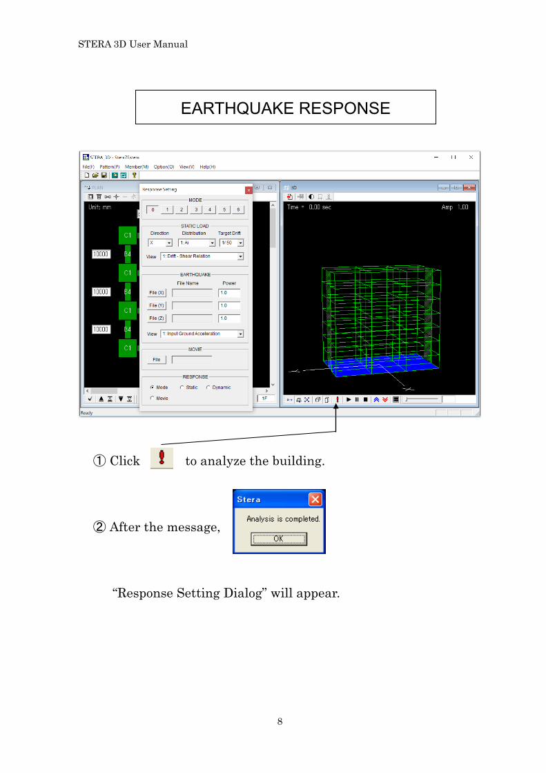
EARTHQUAKE RESPONSE
① Click to analyze the building. ② After the message, “Response Setting Dialog” will appear.

STERA 3D User Manual
9
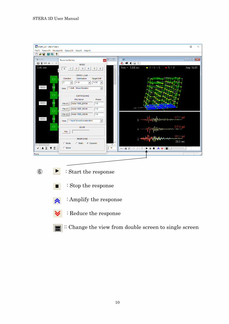
③ : Select X-direction earthquake data file. For example, “Kobe_1995_EW”.
④ : Select Y-direction earthquake data file.
For example, “Kobe_1995_NS”. ⑤ : Select Z-direction earthquake data file.
For example, “Kobe_1995_UD”.
STERA 3D User Manual
10
⑥ : Start the response : Stop the response : Amplify the response : Reduce the response :: Change the view from double screen to single screen

STERA 3D User Manual
11
User Manual

STERA 3D User Manual
12
Index 1 Basic Assumptions .......................................................................................................... 14 2 File Arrangement ............................................................................................................ 16 3 Initial View ...................................................................................................................... 17 4 Setting Member Pattern ................................................................................................. 18 5 Initial Setting of Building and Element ......................................................................... 20 5.1 Element Menu ............................................................................................................. 20 5.2 Activate Element ......................................................................................................... 21 5.3 Change the number of stories, spans .......................................................................... 25 6 Input Element Information ............................................................................................ 26 6.1 RC Column ................................................................................................................... 26 6.2 RC Beam ...................................................................................................................... 29 6.3 RC Wall ........................................................................................................................ 31 6.4 Steel Column ............................................................................................................... 33 6.5 Steel Beam ................................................................................................................... 34 6.6 Steel Wall (Brace) ........................................................................................................ 36 6.7 SRC Column ................................................................................................................ 37 6.8 SRC Beam .................................................................................................................... 38 6.9 SRC Wall ...................................................................................................................... 39 6.10 Column (Direct input for parameters of hysteresis model) ....................................... 40 6.11 Beam (Direct input for parameters of hysteresis model) ........................................... 42 6.12 Wall (Direct input for parameters of hysteresis model) ............................................. 44 6.13 Column (Mixed mode) ................................................................................................. 47 6.14 Beam (Mixed mode) ..................................................................................................... 47 6.15 Wall (Mixed mode) ....................................................................................................... 48 6.16 Floor Slab (2D Rigid) ................................................................................................... 49 6.17 Floor Slab (3D Rigid) ................................................................................................... 49 6.18 Floor Slab (Flexible) .................................................................................................... 50 6.19 Floor Slab (Mix) ........................................................................................................... 51 6.20 Connection Panel ......................................................................................................... 52 6.21 External Spring ........................................................................................................... 53 6.22 Seismic Isolator ........................................................................................................... 55 6.23 Passive Damper ........................................................................................................... 61 6.24 Masonry Wall ............................................................................................................... 65 6.25 Ground Spring (Cone model) ....................................................................................... 67 6.26 Ground Spring (Direct) ................................................................................................ 69

STERA 3D User Manual
13
7 Initial Setting of Analysis Condition .............................................................................. 70 7.1 Restrained freedom, Rigid floor, P-Delta effect, Mass distribution ........................... 70 7.2 Condition of static analysis ......................................................................................... 73 7.3 Condition of dynamic analysis .................................................................................... 76 8 3D View of Building and Response ................................................................................. 78 8.1 3D View of building ..................................................................................................... 78 8.2 Modal analysis ............................................................................................................. 80 8.3 Nonlinear static push-over analysis ........................................................................... 81 8.4 Nonlinear earthquake response analysis ................................................................... 84 8.5 Nonlinear vibrator response analysis ......................................................................... 89 8.6 Wind response analysis ............................................................................................... 90 8.7 Response output member ............................................................................................ 91 8.8 Save Nonlinear Earthquake Response as a Movie File ............................................. 92 8.9 Change Analysis .......................................................................................................... 94 9 Input Earthquake Ground Motion ................................................................................. 95 9.1 Format of input earthquake data file ......................................................................... 95 10 Save and Open Files .................................................................................................... 96 10.1 Save building data ....................................................................................................... 96 10.2 Save results of analysis in text files ........................................................................... 97 10.3 Output text files ........................................................................................................... 99 11 Continuous Analysis .................................................................................................. 116 12 Automatic generation of Lumped Mass Model (LMM) ............................................ 117 13 Command line execution ........................................................................................... 121

STERA 3D User Manual
14
1 Basic Assumptions
1) In the default setting, a floor diaphragm is considered to be rigid for in-plane deformation and free for out-of-plane deformation. Elastic deformation of a floor diaphragm for in-plane deformation can be considered by selecting the FEM model in the option menu.
2) All structural elements are modeled by line-elements with nonlinear springs except the floor diaphragm which can be by a FEM model.
3) Beam element is represented by the model with nonlinear flexural springs at the both ends and a nonlinear shear spring in the middle of the element,
4) Column element is represented by the MS (multi spring) model with nonlinear axial springs in the sections of the both ends and two directional nonlinear shear springs in the middle of the element by default,
5) Wall element is represented by the MS (multi spring) model with nonlinear axial springs in the sections of the both ends and nonlinear shear springs in the middle of the wall panel as well as in the two side columns by default,
6) Steel brace is represented by the truss element,
7) Base-isolation element is represented by the MSS (multi shear spring) model with nonlinear shear springs in X-Y plane,
8) Energy dissipation dampers and masonry element are introduced as nonlinear shear springs in a frame,
9) Shear deformation of connection panel between beam and column is considered by selecting elastic connection in the option menu.
10) In the default setting, structural damping is proportional damping to initial stiffness. It can be changed to be other types of damping by the option menu.

STERA 3D User Manual
15
11) Rebar sizes follow U.S. and Japanese standards, but can be changed to Euro standards, etc. in the options menu.
Other assumptions and details are written in “Technical Manual”.

STERA 3D User Manual
16
2 File Arrangement Please check if you have the following files and folders in the folder “STERA 3D V*.*”:
Stera_3D_J.exe … Main program
Response.exe … Sub-program for response output input / … Folder for input (empty)
output/ … Folder for output (empty)
manual/ … Folder for manuals
STERA_user_manual
STERA_technical_manual
sample/ … Folder for sample
building/ … Folder for sample building for STERA
wave/ … Folder for sample input waves
Please keep them in the same folder.

STERA 3D User Manual
17
3 Initial View
Please double crick “Stera 3D.exe” The left view is “PLAN EDIT VIEW” where you input building plan data, and the right view is “3D VIEW” where you can see the building shape and its response after the analysis. To open the building data already saved, [File] [Open], and select the file.
PLAN EDIT VIEW 3D VIEW

STERA 3D User Manual
18
4 Setting Member Pattern
“PLAN EDIT VIEW” starts from 1st floor (1F) of a building.
- Please click the place you want to set. - Please click again to change the element. It will be changed in the following order:
Column (green) Empty Column(green) Beam (green) Wall (dark green) Empty Beam (green)
But, in case of the basement floor (BF), the order is changed as: Base Spring (brown) Empty Base Spring (brown)
Current story Story height
Story weight
Span (mm)

STERA 3D User Manual
19
If you select Masonry element, Damper element, Isolator element, External Spring, Column (green) Isolator (brown) Empty Column(green) Beam (green) Wall (dark green) Damper (brown) Masonry (brown)
External Spring (brown) Empty Beam (green) If you click while holding down the control key (Ctrl), you can delete immediately.
- By dragging your mouse in a region, you can set all the elements in the region at once. - By clicking the right button of your mouse, you can change the number of element type
for column (C1-C100), for beam (B1-B100), and for wall (W1-W100) etc. - To move to another floor and copy or clear the member patterns, you can use the
following buttons arranged at the bottom of the PLAN EDIT VIEW:
You can check the arrangement of members on the “3D VIEW”.
Move to upper floor
Copy lower pattern
Move to lower floor
Clear all patterns
Copy upper pattern

STERA 3D User Manual
20
5 Initial Setting of Building and Element 5.1 Element Menu
Column
Beam
Wall
Masonry (option)
BASE SPRING (only BF)
Connection panel
Slab (option)
Max size of building
Black and White view
Passive damper (option)
Output member
Isolator (option)

STERA 3D User Manual
21
5.2 Activate Element
In the default condition, - All columns, beams and walls are reinforced concrete elements, - Other elements are non-active in the element menu. To change structural type and activate other elements, please select “Option” in the main menu and select “Member” from the pull down menu.

STERA 3D User Manual
22
Option Member
[1] Column, [2] Beam, [3] Wall RC: Reinforced concrete, S: Steel, SRC: Steel Reinforced Concrete, Direct: Direct input of force and displacement, Mix: Mixed mode
[1]
[2]
[3]
[4]
[5]
[7]
[8]
[9]
[10]
[11]
[6]
[12] [13]
[14]
If you select [RC], [S], [SRC], [Direct], all members will have the same structure. Therefore, the message will appear asking “Clear all member information?”.
If you select [Mix], you can use different structure for each member.
STERA 3D User Manual
23
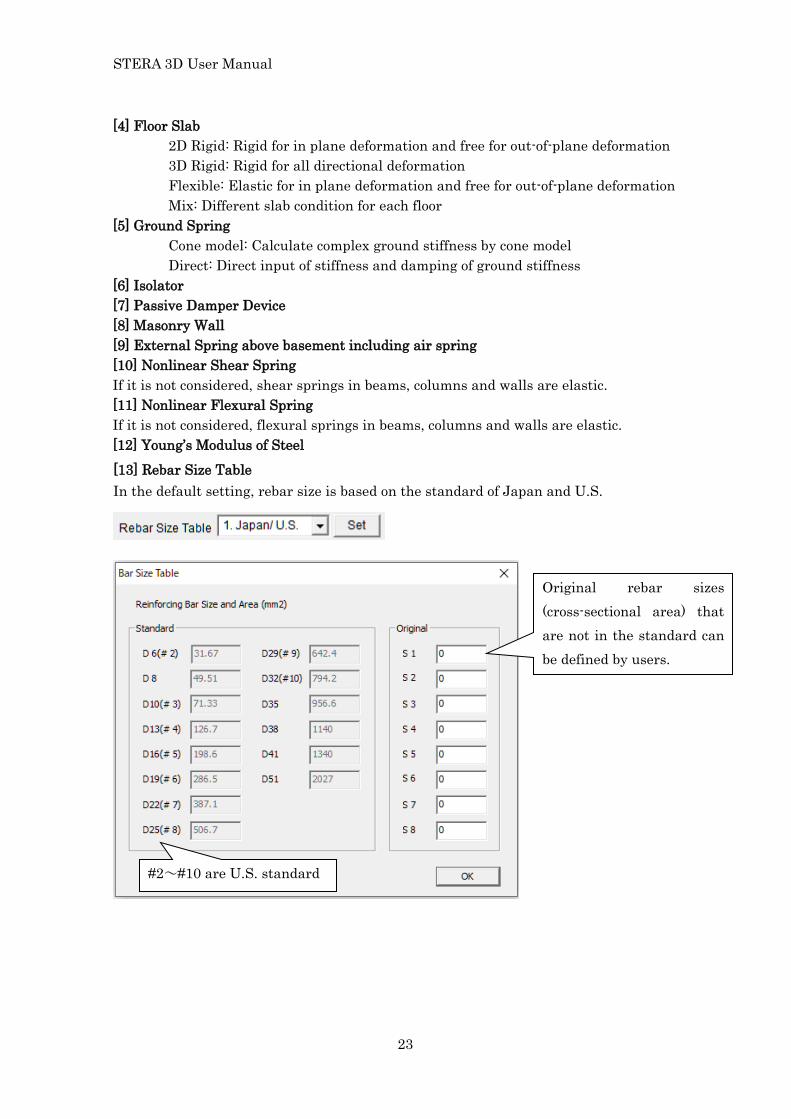
[13] Rebar Size Table In the default setting, rebar size is based on the standard of Japan and U.S.
#2~#10 are U.S. standard
Original rebar sizes (cross-sectional area) that are not in the standard can be defined by users.
[4] Floor Slab 2D Rigid: Rigid for in plane deformation and free for out-of-plane deformation 3D Rigid: Rigid for all directional deformation Flexible: Elastic for in plane deformation and free for out-of-plane deformation Mix: Different slab condition for each floor
[5] Ground Spring Cone model: Calculate complex ground stiffness by cone model Direct: Direct input of stiffness and damping of ground stiffness [6] Isolator [7] Passive Damper Device [8] Masonry Wall [9] External Spring above basement including air spring [10] Nonlinear Shear Spring If it is not considered, shear springs in beams, columns and walls are elastic. [11] Nonlinear Flexural Spring If it is not considered, flexural springs in beams, columns and walls are elastic. [12] Young’s Modulus of Steel
STERA 3D User Manual
24
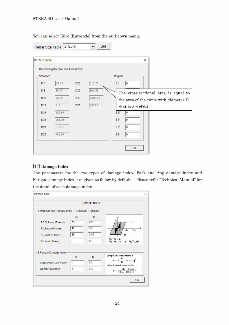
You can select Euro (Eurocode) from the pull-down menu.
[14] Damage Index The parameters for the two types of damage index, Park and Ang damage index and Fatigue damage index, are given as follow by default. Please refer “Technical Manual” for the detail of each damage index.
The cross-sectional area is equal to the area of the circle with diameter D, that is A = πD2/4

STERA 3D User Manual
25
5.3 Change the number of stories, spans
MAX. SIZE OF BUILDING ( )
You can change the maximum number of spans and stories of the building. The default setting is
Story : up to 8 Span : up to 3 in X-direction up to 3 in X-direction
The maximum numbers you can select are:
Story : up to 61 Span : up to 30 in X-direction up to 20 in X-direction
After you select new numbers, a dialog will appear asking if you clear all building information or not. If you select “NO”, you can keep the same building information.

STERA 3D User Manual
26
6 Input Element Information 6.1 RC Column
COLUMN ( )
- Please input the section size where d1 and d2 are the distances of X-rebars and Y-rebars respectively. If rebars are arranged in two layers, the distance is determined as the center of rebar area.
- For the number of reinforcing bars and their size, please select the values from the popup windows.
- For steel strength SD and concrete compressive strength Fc, you can input values by changing the default values.
- To move to the next element type, please click [ADD] button.
- You can copy the previous element by [COPY] button.

STERA 3D User Manual
27
“Data_column_rc.txt” is a text file with member data separated by TAB.
- You can set the default values for all members by selecting the last member type “Cdef”.
- You can export member data to a text file by [Export] button. Automatically, the text file, “Data_column_rc.txt” is created in the same folder of STERA_3D.
- You can import member data from a text file by [Import] button. The format of the import file must be the same as the exported file.

STERA 3D User Manual
28
In [OPTION] menu,
- The default steel strength is assumed to be 1.1 times larger than the nominal strength.
- For nonlinear flexural spring, you can select from 1) the model with independent springs for Mx, My and N or 2) MS (multi-spring) model for Mx-My-N nonlinear interaction. The default setting is MS model.
- Shear crack strength Qc is defined as the ratio of the yield strength Qy. The default value is 0.3.
- The default values of yield and ultimate shear deformation angles, Ry and Ru are 0.004 (=1/250) and 0.01 (1/100), respectively.
In [OPTION] menu, the parameters to control the shape of hysteresis model are defined as follows:
- R1: the default value of stiffness degrading ratio in the trilinear hysteresis is 0.5. (0: no degradation)
- R2: the default value of slip stiffness ratio in the trilinear hysteresis is 0.0 (0: no slip).
- R3: the default value of strength degrading ratio in the trilinear hysteresis is 0.0.
Please refer “Technical Manual” for the detail.
- You can identify the numerical integration method in earthquake response analysis from Average Acceleration method or Operator Splitting method. The default is Average Acceleration method which replace the negative stiffness to be a small positive stiffness for the stability of calculation.

STERA 3D User Manual
29
6.2 RC Beam
BEAM ( )
- Please input the section size where d1 and d2 are the distances of upper and bottom rebars. If rebars are arranged in two layers, the distance should be the center of rebar area.
- For the number of reinforcing bars and their size, please select the values from the popup windows.
- For the material strength, SD and Fc, you can input values by changing the default values.
- To move to the next element type, please click [ADD] button.
- You can copy the previous element by [COPY] button.
- You can set default values for all members by selecting the last member type “Bdef”.
- You can export member data to the text file “Data_beam_rc.txt” by [Export] button.
- You can import member data from a text file by [Import] button.
- Please click [OK] to finish.

STERA 3D User Manual
30
In [OPTION] menu,
- The default steel strength is assumed to be 1.1 times larger than the nominal strength.
- Rs: the effective slab width to contribute flexural behavior of beam is assumed to be 0.1 times beam length.
The parameters to control the shape of hysteresis model are defined as follows:
- R1: the default value of stiffness degrading ratio in the trilinear hysteresis is 0.5. (0: no degradation)
- R2: the default value of slip stiffness ratio in the trilinear hysteresis is 0.0 (0: no slip).
- R3: the default value of strength degrading ratio in the trilinear hysteresis is 0.0.
- Ru: the default value of Ultimate rotation angle Ru is 1/50 (=0.02)
- Kp/Ky: the default value of stiffness ratio over Ry is 0.001
- Ku/Ky: the default value of stiffness ratio over Ru is 0.001 (could be negative)

STERA 3D User Manual
31
6.3 RC Wall
WALL ( )
- Please input the section size.
- For the number of reinforcing bars and their size, please select the values from the popup windows.
- For the material strength, SD and Fc, you can input values by changing the default values.
- To move to the next element type, please click [ADD] button.
- You can copy the previous element by [COPY] button.
- You can set default values for all members by selecting the last member type “Wdef”.
- You can export member data to the text file “Data_wall_rc.txt” by [Export] button.
- You can import member data from a text file by [Import] button.
- Please click [OK] to finish.

STERA 3D User Manual
32
In [OPTION] menu,
- The default steel strength is assumed to be 1.1 times larger than the nominal strength. You can change the ratio in [OPTION] menu.
- Considering the early cracks in reinforced concrete walls, you can reduce the shear stiffness by multiplying a reduction factor. The default value is 0.2.
- Considering openings in a wall element, you can reduce the shear strength by multiplying a reduction factor. The default value is 1.0.
- For nonlinear flexural spring, you can select from 1) the model with independent springs for Mx, My, and N or 2) MS (multi-spring) model for Mx-My-N nonlinear interaction. The default setting is MS model.
In [OPTION] menu, the parameters to control the shape of hysteresis model are defined as follows:
- R1: the default value of stiffness degrading ratio in the trilinear hysteresis is 0.5. (0: no degradation)
- R2: the default value of slip stiffness ratio in the trilinear hysteresis is 0.0 (0: no slip).
- R3: the default value of strength degrading ratio in the trilinear hysteresis is 0.0.
Please refer “Technical Manual” for the detail.

STERA 3D User Manual
33
6.4 Steel Column
COLUMN ( )
H-x(I) H-y Box Circle
- Please select the shape of section from the pull-down menu.
- Please input the section size.
- For the material strength, Fy, and Young’ s modulus, E, you can change the default values.
- To move to the next element type, please click [ADD] button.
- You can copy the previous element by [COPY] button.
- You can set default values for all members by selecting the last member type “Cdef”.
- You can export member data to the text file “Data_column_steel.txt” by [Export] button.
- You can import member data from a text file by [Import] button.
- Please click [OK] to finish.
In [OPTION] menu,
- The default steel strength is assumed to be 1.1 times larger than the nominal strength and the stiffness ratio after yielding is 0.001.
- Non-linear hysteresis due to buckling can be considered. The initial setting is “Not considered”. To consider the buckling, you must enter an effective slender ratio.
- For nonlinear flexural spring, you can select from 1) the model with independent springs for Mx and My or 2) MS (multi-spring) model for Mx-My-N nonlinear interaction. The default setting is MS model.
STERA 3D User Manual
34
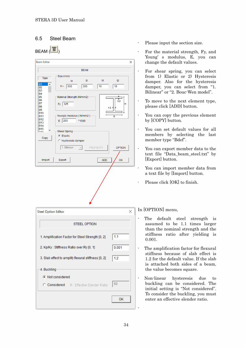
6.5 Steel Beam
BEAM ( )
- Please input the section size.
- For the material strength, Fy, and Young’ s modulus, E, you can change the default values.
- For shear spring, you can select from 1) Elastic or 2) Hysteresis damper. Also for the hysteresis damper, you can select from “1. Bilinear” or “2. Bouc-Wen model”.
- To move to the next element type, please click [ADD] button.
- You can copy the previous element by [COPY] button.
- You can set default values for all members by selecting the last member type “Bdef”.
- You can export member data to the text file “Data_beam_steel.txt” by [Export] button.
- You can import member data from a text file by [Import] button.
- Please click [OK] to finish.
In [OPTION] menu,
- The default steel strength is assumed to be 1.1 times larger than the nominal strength and the stiffness ratio after yielding is 0.001.
- The amplification factor for flexural stiffness because of slab effect is 1.2 for the default value. If the slab is attached both sides of a beam, the value becomes square.
- Non-linear hysteresis due to buckling can be considered. The initial setting is “Not considered”. To consider the buckling, you must enter an effective slender ratio.
-

STERA 3D User Manual
35
For hysteresis damper of shear spring, in [PROPERTY] menu, please input necessary parameters for each hysteresis model. 1. Bilinear
2. Bouc-Wen

STERA 3D User Manual
36
6.6 Steel Wall (Brace)
WALL ( )
*BRB: buckling restrained brace
- If there is a beam upper of Brace element, please select the beam type number from the pop-up menu.
- Please select brace types from the pictures (Type1, 2, 3, 4, 5).
- You can select Axial force deformation relationship from “Elastic” and “Hysteresis”. Non-linear hysteresis due to buckling can be selected from “1.(BRB) Bilinear” and “Wakabayashi”.
- To move to the next element type, please click [ADD] button.
- You can copy the previous element by [COPY] button.
- You can set default values for all members by selecting the last member type “Wdef”.
- You can export member data to the text file “Data_brace.txt” by [Export] button.
- You can import member data from a text file by [Import] button.
- Please click [OK] to finish.
In [PROPERTY] menu,
- Please input “Area of single brace”, “Steel strength”, and “Effective slender ratio”.

STERA 3D User Manual
37
6.7 SRC Column
COLUMN ( )
- RC part is the same as RC Column. - [OPTION] menu is the same as RC Column. - Please input Steel size (h1, b1, tw, tf). - Please input Steel strength (Fy).
- To move to the next element type, please click [ADD] button. - You can copy the previous element by [COPY] button. - You can set default values for all members by selecting the last member type “Cdef”. - You can export member data to the text file “Data_column_src.txt” by [Export] button. - You can import member data from a text file by [Import] button. - Please click [OK] to finish.
STERA 3D User Manual
38
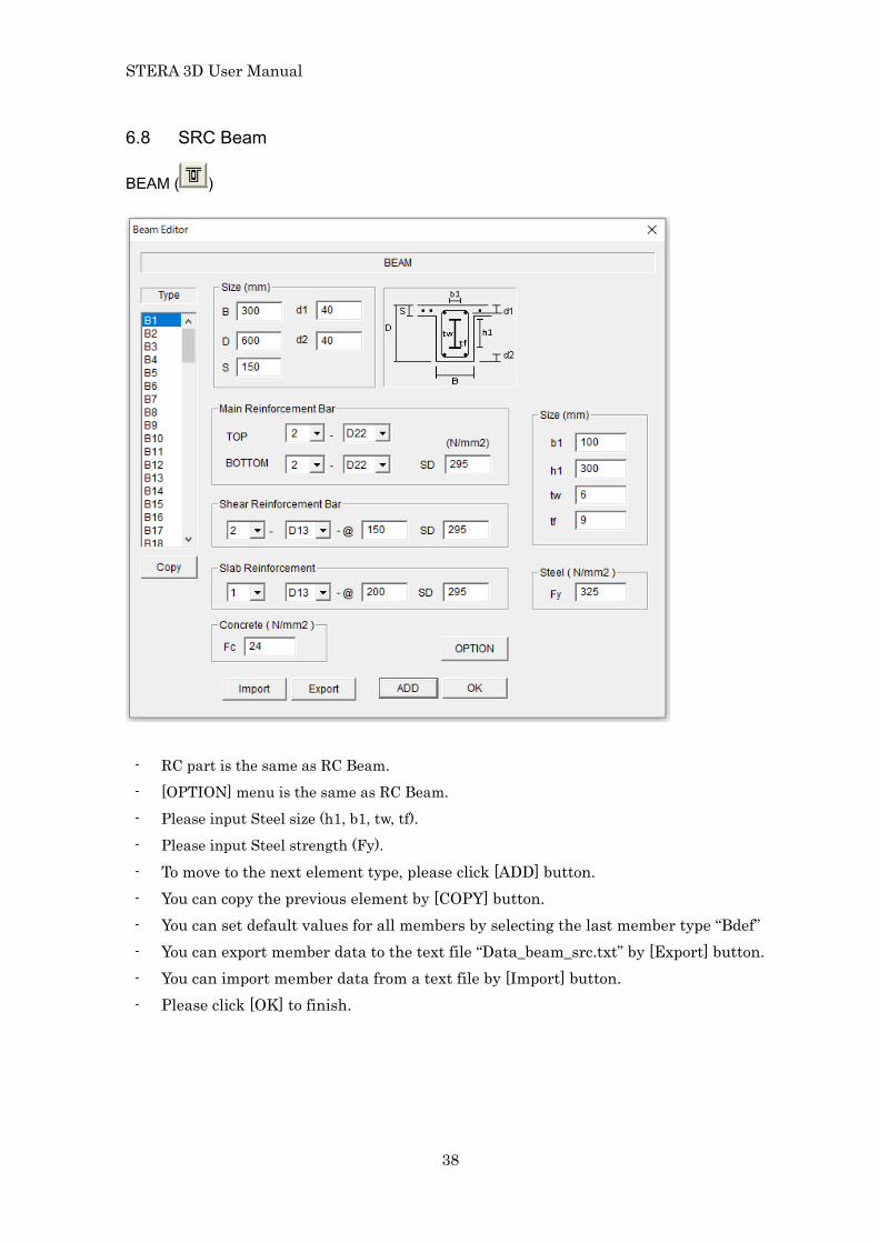
6.8 SRC Beam
BEAM ( )
- RC part is the same as RC Beam. - [OPTION] menu is the same as RC Beam. - Please input Steel size (h1, b1, tw, tf). - Please input Steel strength (Fy).
- To move to the next element type, please click [ADD] button. - You can copy the previous element by [COPY] button. - You can set default values for all members by selecting the last member type “Bdef” - You can export member data to the text file “Data_beam_src.txt” by [Export] button. - You can import member data from a text file by [Import] button. - Please click [OK] to finish.
STERA 3D User Manual
39
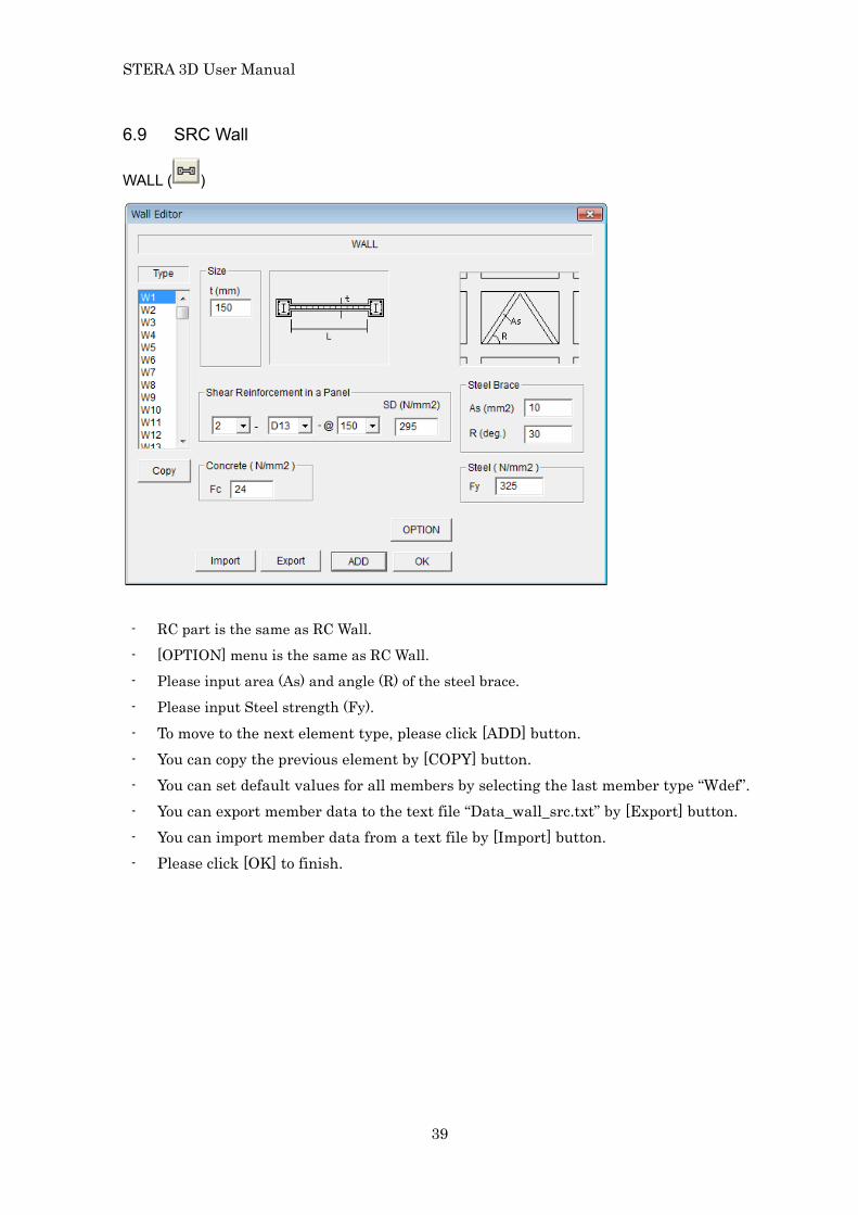
6.9 SRC Wall
WALL ( )
- RC part is the same as RC Wall. - [OPTION] menu is the same as RC Wall. - Please input area (As) and angle (R) of the steel brace. - Please input Steel strength (Fy).
- To move to the next element type, please click [ADD] button. - You can copy the previous element by [COPY] button. - You can set default values for all members by selecting the last member type “Wdef”. - You can export member data to the text file “Data_wall_src.txt” by [Export] button. - You can import member data from a text file by [Import] button. - Please click [OK] to finish.

STERA 3D User Manual
40
6.10 Column (Direct input for parameters of hysteresis model)
COLUMN ( )
- Please input the section size that is used for Rigid zone of column-beam connection Area of section A = BD Moment of inertia, Ix = BD3/12, Iy = DB3/12
- Please input Young’s modulus (E) of material that is used for Axial stiffness of the section EA Initial flexural stiffness K0 = 6EI/L (L is the member length)
- Please input parameters for moment-rotation relationship about Y axis. - Please input parameters for moment-rotation relationship about X axis. - Please select structural type between [RC] and [S](steel).
[RC] uses stiffness degrading hysteresis model [S] uses normal trilinear hysteresis model
- To move to the next element type, please click [ADD] button. - You can copy the previous element by [COPY] button. - You can set default values for all members by selecting the last member type “Cdef”. - You can export member data to the text file “Data_column_direct.txt” by [Export]
button. - You can import member data from a text file by [Import] button. - Please click [OK] to finish.
X
Z
Y
yM yM
xM
xM

STERA 3D User Manual
41
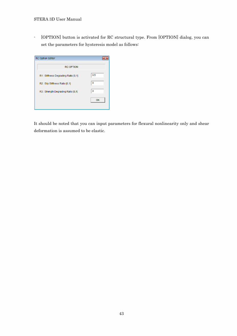
- [OPTION] button is activated for RC structural type. From [OPTION] dialog, you can set the parameters for hysteresis model as follows:
It should be noted that you can input parameters for flexural nonlinearity only and shear deformation is assumed to be elastic.

STERA 3D User Manual
42
6.11 Beam (Direct input for parameters of hysteresis model)
BEAM ( )
-
- Please input the section size that is used for Rigid zone of column-beam connection Area of section A = BD Moment of inertia, Iy = BD3/12, Iz = DB3/12
- Please input Young’s modulus (E) of material that is used for Axial stiffness of the section EA Initial flexural stiffness K0 = 6EI/L (L is the member length)
- Please input parameters for moment-rotation relationship in lower bending. - Please input parameters for moment-rotation relationship in upper bending. - Please select structural type between [RC] and [S](steel).
[RC] uses stiffness degrading hysteresis model [S] uses normal trilinear hysteresis model
- To move to the next element type, please click [ADD] button. - You can copy the previous element by [COPY] button. - You can set default values for all members by selecting the last member type “Bdef”. - You can export member data to the text file “Data_Beam_Direct.txt” by [Export]
button. - You can import member data from a text file by [Import] button. - Please click [OK] to finish.
STERA 3D User Manual
43
- [OPTION] button is activated for RC structural type. From [OPTION] dialog, you can set the parameters for hysteresis model as follows:
It should be noted that you can input parameters for flexural nonlinearity only and shear deformation is assumed to be elastic.

STERA 3D User Manual
44
6.12 Wall (Direct input for parameters of hysteresis model)
WALL ( )
[1] Linear model
- It consists of shear spring, bending spring and axial spring.
- Please select hysteresis types for shear and bending springs from the pull down menu.
- You can input the parameters of the hysteresis in [PROPERTY] view.
- Please input vertical stiffness directly. - You can set default values for all
members by selecting the last member type “Ddef”.
- You can export member data to the text file “Data_wall_direct.txt” by [Export] button.
- You can import member data from a text file by [Import] button.
Shear spring (Qs -Ds)
Bending spring (Qb -Db)
Qs Ds
Mb
θb
h
Q b = Mb / h
D b = θb h

STERA 3D User Manual
45
[2] Bi-linear model
Shear spring (Qs -Ds) Bending spring (Qb -Db)
[3] Normal-Trilinear model
Shear spring (Qs -Ds) Bending spring (Qb -Db)

STERA 3D User Manual
46
[4] Degrading Trilinear model
Shear spring (Qs -Ds) Bending spring (Qb -Db)

STERA 3D User Manual
47
6.13 Column (Mixed mode)
COLUMN ( )
6.14 Beam (Mixed mode)
BEAM ( )
- You can select different “Structural Type” for each member type (C1, C2, …).
- You can input member properties by [PROPERTY] button.
- To move to the next element type, please click [ADD] button.
- You can copy the previous element by [COPY] button.
- You can set default values for all members by selecting the last member type “Cdef”.
- You can select different “Structural Type” for each member type (B1, B2, …).
- You can input member properties by [PROPERTY] button.
- To move to the next element type, please click [ADD] button.
- You can copy the previous element by [COPY] button.
- You can set default values for all members by selecting the last member type “Bdef”.

STERA 3D User Manual
48
6.15 Wall (Mixed mode)
WALL ( )
- You can select different “Structural Type” for each member type (W1, W2, …).
- You can input member properties by [PROPERTY] button.
- To move to the next element type, please click [ADD] button.
- You can copy the previous element by [COPY] button.
- You can set default values for all members by selecting the last member type “Wdef”.

STERA 3D User Manual
49
6.16 Floor Slab (2D Rigid) - Rigid for in plane deformation and free for out-of-plane deformation. In plane
deformations at nodes are dependent to those of center of gravity. 6.17 Floor Slab (3D Rigid) - Rigid for all directional deformation. Deformations at nodes are dependent to those of
center of gravity.
(a) In plane deformation (b) Out of plane deformation
(c) Independent freedom for 2D Rigid
(d) Independent freedom for 3D Rigid
STERA 3D User Manual
50
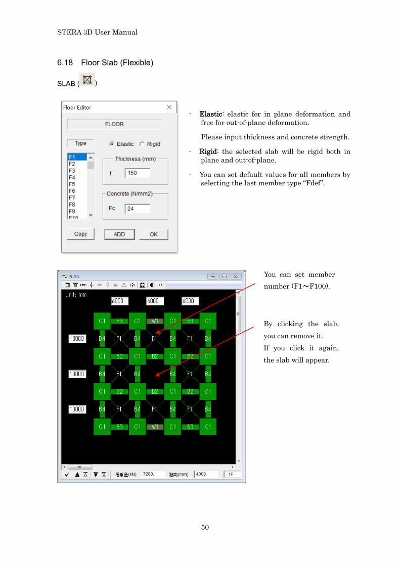
6.18 Floor Slab (Flexible)
SLAB ( )
- Elastic: elastic for in plane deformation and free for out-of-plane deformation.
Please input thickness and concrete strength.
- Rigid: the selected slab will be rigid both in plane and out-of-plane.
- You can set default values for all members by selecting the last member type “Fdef”.
You can set member number (F1~F100).
By clicking the slab, you can remove it. If you click it again, the slab will appear.
STERA 3D User Manual
51
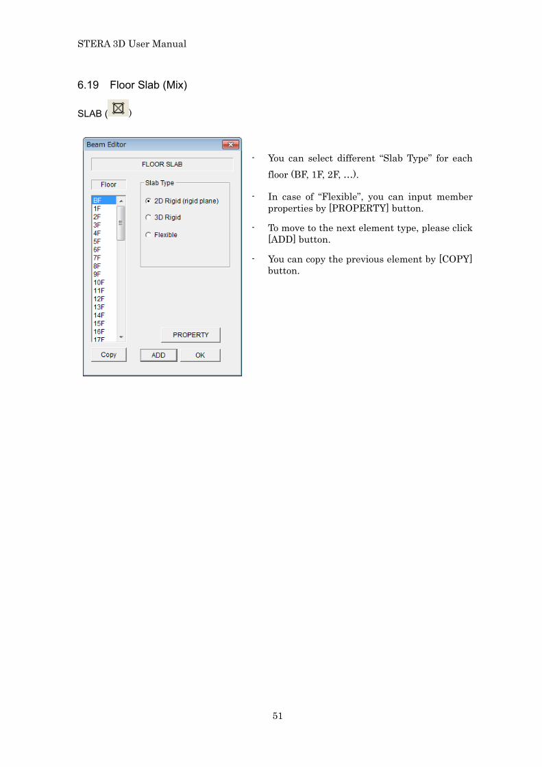
6.19 Floor Slab (Mix)
SLAB ( )
- You can select different “Slab Type” for each floor (BF, 1F, 2F, …).
- In case of “Flexible”, you can input member properties by [PROPERTY] button.
- To move to the next element type, please click [ADD] button.
- You can copy the previous element by [COPY] button.

STERA 3D User Manual
52
6.20 Connection Panel
CONNECTION PANEL ( )
Rigid Zone Panel Zone
You can set the ratio of the length of rigid zone or panel zone inside connection area. The default value is 1.0 (to the member face).

STERA 3D User Manual
53
6.21 External Spring
EXTERNAL SPRING ( ) (NOTE: only available at the Basement Floor or you
select External Spring in Option menu. Default is PIN)
Elastic Lift up Air Spring
- In case of “Elastic” and “Lift Up” spring
- You can select “Pin” support or “Spring” support. The default setting is “Pin”.
- As for “Spring”, you can select from “Elastic” spring”, “Lift up” spring” and “Air Spring”.
- To move to the next element type, please click [ADD] button.
- You can copy the previous element by [COPY] button.
- You can set default values for all members by selecting the last member type “Sdef”.
- Please input spring stiffness from the [PROPERTY] menu.

STERA 3D User Manual
54
“Elastic” and “Lift Up” spring can be used between ground and building.
- In case of “Air Spring”
- Please input spring properties from the [PROPERTY] menu. The air spring force is expressed as
( )1 0F K z y K z= − +
( )1 1BK z y C y− = ⋅
Please refer “Technical Manual” for the detail.
0K 1K
1C
F
z
y

STERA 3D User Manual
55
6.22 Seismic Isolator
ISOLATOR ( ) (NOTE: only available when you select Isolator in Option menu)
You can select Isolator device from the pull-down menu: 1. NRB (Natural Rubber Bearing) 2. LRB (Lead Rubber Bearing) 3. HDRB (High Damping Rubber Bearing) 4. Lead Damper 5. Elastic Slide Bearing 6. Original Isolator Please read “STERA3D_technical_manual” about the detail of each device.
(in case of 6 springs)
- The default value of the ratio between vertical stiffness, KV, and the horizontal stiffness, K0, is 1000.
- You can select the number of multi-springs from the pull-down menu (2, 4, 6, 8, 10).
- You can set default values for all members by selecting the last member type “Idef”.
- You can export member data to the text file “Data_isolator.txt” by [Export] button. - You can import member data from a text file by [Import] button. - Please click [OK] to finish.

STERA 3D User Manual
56
[1] NRB Isolator
- For NRB isolator, you can select “Linear” or “Hardening” hysteresis.
- Please input spring property by [PROPERTY] button.
In case of “Hardening”
In case of “Linear”

STERA 3D User Manual
57
[2] LRB Isolator
- For LRB isolator, you can select “Normal Bi-Linear” or “Modified Bi-Linear” hysteresis.
- Please input spring property by [PROPERTY] button.
In case of “Normal Bi-Linear”
In case of “Modified Bi-Linear” - In case of “Modified Bi-Linear” hysteresis,
you can consider strength reduction by energy dissipation.
STERA 3D User Manual
58
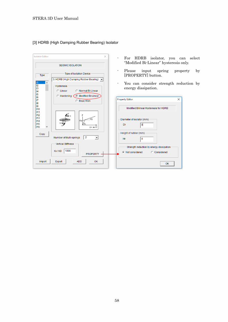
[3] HDRB (High Damping Rubber Bearing) Isolator
- For HDRB isolator, you can select “Modified Bi-Linear” hysteresis only.
- Please input spring property by [PROPERTY] button.
- You can consider strength reduction by energy dissipation.

STERA 3D User Manual
59
[4] Lead Damper
[5] Elastic Slide Bearing
- For Lead Damper, you can select “Normal Bi-Linear” hysteresis only.
- Please input spring property by [PROPERTY] button.
- You can consider strength reduction by energy dissipation.
- For Elastic Slide Bearing, you can select “Normal Bi-Linear” hysteresis only.
- Please input spring property by [PROPERTY] button.
- You can consider strength reduction by energy dissipation.

STERA 3D User Manual
60
[6] Original Isolator
- If you want to use your original isolator device, please select “Original Isolator”. You can select the hysteresis from “Linear”, “Normal Bi-Linear”, and “Bouc-Wen”.
- Please input spring property by [PROPERTY] button.
In case of “Bouc-Wen”
Alpha = α , Beta = β , Gamma = γ
A = 0A
D_A = Aδ , D_Myu = νδ , D_Eta= ηδ ,
Definition of Bouc-Wen Model (Please refer “Technical Manual” for the detail.)

STERA 3D User Manual
61
6.23 Passive Damper
PASSIVE DAMPER ( ) (NOTE: only available when you select Passive Damper
in Option menu)
[1] Elastic spring
- Please select damper type from Elastic, Hysteresis and Viscous and its detail characteristics from the pull down menu.
- If there is a reinforcement concrete beam upper of Damper, please select the upper beam type number from the pop-up menu. The default is “rigid beam”.
- You can set default values for all members by selecting the last member type “Ddef”.
- You can export member data to the text file “Data_damper.txt” by [Export] button.
- You can import member data from a text file by [Import] button.
- You can input the detail characteristic of the Damper in [PROPERTY] view.
- Please click [OK] to finish.
STERA 3D User Manual
62
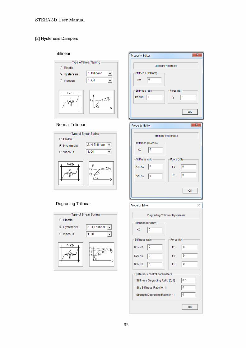
[2] Hysteresis Dampers
Bilinear
Normal Trilinear
Degrading Trilinear

STERA 3D User Manual
63
Bouc-Wen
Poly-linear Slip
STERA 3D User Manual
64
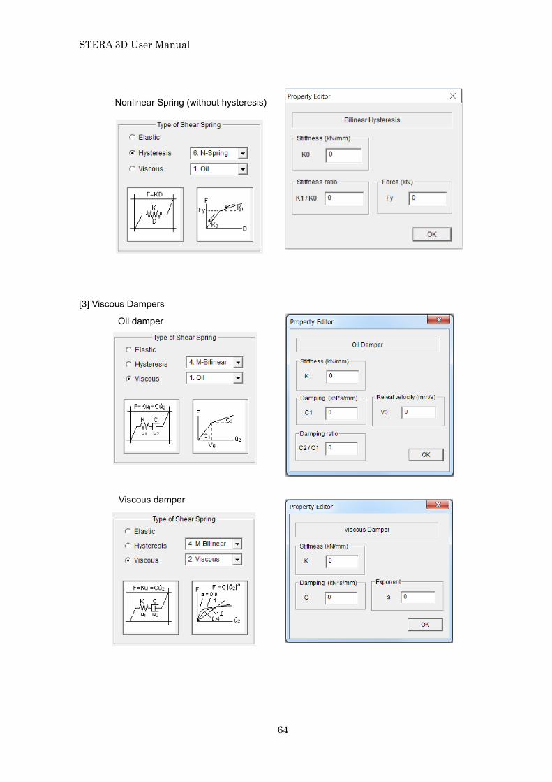
[3] Viscous Dampers
Oil damper
Viscous damper
Nonlinear Spring (without hysteresis)

STERA 3D User Manual
65
6.24 Masonry Wall
MASONRY ( ) (NOTE: only available when you select Masonry in Option menu)
- Please input the size of brick unit and thickness of mortal and compression strength of these materials.
- If there is a reinforcement concrete beam upper of Masonry Wall as shown below, please select the upper beam type number from the pop-up menu. The default is “rigid beam”.
- You can set default values for all members by selecting the last member type “Mdef”.
- You can export member data to the text file “Data_masonry.txt” by [Export] button.
- You can import member data from a text file by [Import] button.
- You can input the detail characteristic of the Damper in [PROPERTY] view.
- Please click [OK] to finish.
upper beam

STERA 3D User Manual
66
- If there is an opening in wall element, you can reduce the stiffness and shear strength by multiplying reduction factors in [OPTION] menu. The default values are 1.0
- Since the backbone curve of the shear spring has the negative stiffness after yielding, you can identify the numerical integration method in earthquake response analysis from Average Acceleration method or Operator Splitting method. The default is Average Acceleration method.

STERA 3D User Manual
67
6.25 Ground Spring (Cone model)
GROUND SPRING ( ) (NOTE: only available when you select Cone model in
Option menu)
- Please input thickness and soil properties in each layer. - Since the relationship 2
0 SG rV= holds, if any two variables are input, the remaining variable is automatically calculated.
- Also, since the relationship ( )
( )2
2
2 11 2
P
S
pVV p
−=
−holds, if any one variable except SV is
input, the remaining variable is automatically calculated. - Please input the size of foundation. - Please input the number of the layer which is regarded as an engineering bedrock. - Please input the properties of piles by [Pile] button. - Please input the weight the basement by [Basement Weight] button. - Please select “Radiation Damping” to consider or not.
- To move to the next layer, please click [ADD] button. - You can copy the previous layer by [COPY] button. - You can set default values for all layers by selecting the last layer type “Gdef”. - You can export layer data to the text file “Data_ground_cone.txt” by [Export] button. - You can import layer data from a text file by [Import] button. - Please click [OK] to finish.

STERA 3D User Manual
68
When you click [Pile] button, the input window of pile location and property appears.
When you click [Basement Weight] Button, the input window of basement weight appears.

STERA 3D User Manual
69
6.26 Ground Spring (Direct)
GROUND SPRING ( ) (NOTE: only available when you select Direct in Option menu)
- Please input Sway spring properties , Ch hK and Rocking spring properties , Cr rK in
each direction. - By [Basement Weight] button, please input the weight and rotational inertia weight of
the basement.
- You can export member data to the text file “Data_ground_direct.txt” by [Export] button.
- You can import member data from a text file by [Import] button. - Please click [OK] to finish.
,h xK
,h xC r,yK r,yC
,yhK ,yhC
r,xK r,xC

STERA 3D User Manual
70
7 Initial Setting of Analysis Condition 7.1 Restrained freedom, Rigid floor, P-Delta effect, Mass distribution In the default condition, - The number of freedom at each node is eight including three horizontal deformations,
three rotational deformations and two shear deformations. - The P-Delta effect for column and wall elements is not considered. - The mass of floor is distributed in proportion to influence area To change the default condition, please select “Option” in the main menu and select “Structure” from the pull down menu.

STERA 3D User Manual
71
Option Structure
[1] Restrained freedom number Please indicate the freedom numbers to be restrained. [2] P-Delta Effect Considered P-Delta effect is considered in element stiffness matrix of column and wall. [3] Mass distribution at nodes in a floor Please select from: - Same at all nodes - In proportion to influence area (default) - Independent at each node
[1]
[2] [3]

STERA 3D User Manual
72
- After the initial analysis (see Chapter 8.1), the file “weight_distribution.txt” is
automatically created in the “input” folder. When you want to set different weight at each node, please modify this file and rename it.
- Independent at each node By clicking “Import” button, please select the file of the weight distribution.
Floor
Weight (N) at node (Column position)

STERA 3D User Manual
73
7.2 Condition of static analysis In the default condition, - Static push over analysis will be done with 500 steps until the target drift. To change the default condition, please select “Option” in the main menu and select “Analysis” and “Static” from the pull down menu.
Option Analysis Static
- Cyclic loading is possible by setting the target drift angle at the top of a building in each loading segment.
No. of Maximum Segment
The total number of segments in cyclic loading,
No. of Steps in Segment
Number of calculation steps in each segment for static analysis to increase the accuracy of nonlinear analysis,
- Loading program is defined by the target drift angle, D1, D2 … D150, at the top of a building in each loading segment. If a negative value is entered, the force is applied in the opposite direction.
- To move to the next drift angle, please click [ADD] button.

STERA 3D User Manual
74
[1] Load Distribution along the Height In “8.3 Nonlinear static push-over analysis”, you can select the load distribution along the height from 1. Ai 2. Triangular 3. Uniform 4. UBC 5. ASCE 6. Mode 7. User defined If you want to use [7. User defined] distribution, please create the load distribution file as follows. Firstly, in the initial analysis (see 8.1), a file of the horizontal load distribution is automatically created as "load_distribution.txt" in the “input” folder.
Please modify this file and specify the load distribution (ratio) for each story and rename the file.
Then, by clicking select this file.
Floor Load distribution (ratio)
This example shows the concentrated load at the 7th story (top slab of 7th story).
[1] [2]

STERA 3D User Manual
75
[2] Drift Angle History
You can export the drift angle history to the text file “Drift_history.txt” by [Export] button.
You can import the drift angle history from a text file by [Import] button.
To make the original drift angle history, first, please export an arbitrary history into “Drift_history.txt”. Then, please modify this file and input the original drift angle history in the same format.
Drift_history.txt
Modify the data and input a new drift angle history.
Import the modified file.

STERA 3D User Manual
76
7.3 Condition of dynamic analysis To change the default condition, please select “Option” in the main menu and select “Analysis” and “Dynamic” from the pull down menu.
Option Analysis Dynamic
- No. of Subdivision of Time
Separating the original time interval of input earthquake into a smaller time interval will increase accuracy and stability in numerical integration, however, it also increases calculation time.
- The maximum data size input earthquake is 60,000.

STERA 3D User Manual
77
- Damping
Three types of damping matrix are available:
[C] = a[K0] : proportional to [K0]
[C] = a[Kp] : proportional to [Kp]
[C] = a[K0]+b[M] : Rayleigh damping
The first mode damping factor, h1, is used for type 1) and 2). The second mode damping factor, h2, is used for type 3).
- Numerical Integration Method
You can select the method from the “Average Acceleration Method” and the “Operator Splitting Method”.
- Input Motion
- You can select input motion from “Earthquake” ground acceleration, “Vibrator” on a floor and “Wind” pressure.
- Filter to get Ground Displacement
You can set the parameters of Butterworth band-pass filter to get the ground displacement. The default values are: Low cut filter frequency: 0.1Hz High cut filter frequency: 20Hz Order of filtering: 10 Please check “Technical Manual” for the detail.

STERA 3D User Manual
78
8 3D View of Building and Response
8.1 3D View of building
Move
Default size
Rotation
Enlarge / Reduce
Actual size
Analysis Start
Pause
Stop
Amplify
Decrease
View separation
Speed

STERA 3D User Manual
79
[1] [Default] ( ) set the default size. [Actual] ( ) use the actual size based on
input data.
[2] If the [Analyze] ( ) is activated, by clicking the button, you can make an initial
analysis for getting natural periods and mode shapes. If the analysis is successfully done, the following message will appear on the screen. By clicking [OK] button, RESPONSE SETTING DIALOG will also appear.
Modal analysis
Nonlinear Static
Push-Over Analysis
Nonlinear Earthquake
Response Analysis
Play movie
Change analysis

STERA 3D User Manual
80
8.2 Modal analysis
[1] On the RESPONSE SETTING DIALOG, please click the MODE number from [0] to [6]
to see the view of mode shape and the value of natural period (Period) and effective
modal mass ratio (Mx, My, Mz).
[2] On the 3D VIEW, ( ) starts the vibration of each mode, ( ) stops the vibration
and ( ) pauses the vibration.
[3] ( ) amplifies the response. ( ) reduces the response.
[4] Slider ( ) changes the speed of vibration.
[5] ( ) will save the results into text files.
[6] ( ) changes the color of the view to be black and white.
[5] [6]
[1]
[2]
[4] [3]

STERA 3D User Manual
81
8.3 Nonlinear static push-over analysis [1] Please set loading conditions for the STATIC LOAD:
“Direction”: please select loading direction from the menu. 1. X 2. –X (opposite to X) 3. Y 4. -Y (opposite to Y)
“Distribution”: please select a loading distribution along the height of the building. The load is applied at the center of gravity in each floor. 1. Ai 2. Triangular 3. Uniform 4. UBC 5. ASCE 6. Mode 7. User defined
“Target Drift”: please set the target drift ratio which is defined by the ratio between the top displacement and the height of the building. 1. 1/50 2. 1/100 3. 1/200 4. Cyclic
[2] Please select the response for the lower view window.
[3] On the 3D VIEW, ( ) starts, ( ) pauses and ( ) stops the response.
[4] ( ) will change the view from 2-screens to 1-screen and vice versa.
[1] [3] [2]
Progress bar
U (ductility factor) < 5 moderate damage
U (ductility factor) > 5 severe damage
[4]

STERA 3D User Manual
82
1: Drift-Shear Relation Relationship between Story Drift and Story Shear Coefficient (Story Shear / Total Weight)
2: Capacity Curve Capacity curve for equivalent 1DOF system

STERA 3D User Manual
83
3: Member Response Moment rotation relationships of the designated member (with red circle): - both ends for Beam - X and Y at bottom for Column

STERA 3D User Manual
84
8.4 Nonlinear earthquake response analysis (in case “Earthquake” is selected in the Option menu of dynamic analysis)
[1] On the RESPONSE SETTING DIALOG, please set earthquake data:
“File(X)”: Please select earthquake input file for X-direction. “File(Y)”: Please select earthquake input file for Y-direction. “File(Z)”: Please select earthquake input file for Z-direction (up-down). “Power”: Set the value to amplify the original earthquake The format of the input file is described in Section 9.1.
[2] Please select the response for the lower view window.
[3] On the 3D VIEW, ( ) starts, ( ) pauses and ( ) stops the response.
In the lower view, you can see the input earthquake wave and present status.
[4] ( ) will change the view from 2-screen to 1-screen and vise versa.
[5] ( ) will save the response animation as a movie file (see 5-5).
[6] ( ) will switch on and off to include ground movement.
[1] [3] [4] [2]
[5] [6]

STERA 3D User Manual
85
1: Input Earthquake Ground Motion Earthquake ground acceleration wave in horizontal direction (X and Y) and vertical direction (Z)
2: Input Ground Displacement Earthquake ground displacement wave in horizontal direction (X and Y) and vertical direction (Z)

STERA 3D User Manual
86
3: Top Displacement Response Top displacement at the center of gravity
4: Orbit of Top Displacement Orbit of the top displacement at the center of gravity

STERA 3D User Manual
87
5: Base Shear - Top Drift Top displacement and base shear coefficient relationship
6: Energy Response K: Kinematics Energy N: Energy dissipation by Nonlinear Dampers F: Energy dissipation by Frame members D: Energy dissipation by Viscous Damper
The figure shows the cumulative response in the order D, F, N, K.

STERA 3D User Manual
88
7: Member Response M-θ relationships of the designated member: - both ends for Beam - X and Y at bottom for Column

STERA 3D User Manual
89
8.5 Nonlinear vibrator response analysis (in case “Vibrator on the Floor” is selected in the Option menu of dynamic analysis)
- Floor number and the direction of movement (X or Y) to set the vibrator.
- Loading force (kN) can be selected from “Sine” wave and “Random” wave.
- In case of “Sine” wave, you input amplitude and natural period.
- In case of “Random” wave. You select an input file from the dialog window.
1. Input Vibrator Force 2. Top Building Acceleration
Top acceleration at the center of gravity
3. Top Building Acceleration Top displacement at the center of gravity
The following menu is the same as Earthquake analysis.

STERA 3D User Manual
90
8.6 Wind response analysis (in case “Wind” is selected in the Option menu of dynamic analysis)
The dynamic wind force is assumed to be applied at the center of gravity at each floor with the constant
distribution along the height of the building.
( )ih W t
( )xW t
( )yW t
( )zW t
- Wx (kN): Please select an input file for wind lateral force in x-direction.
- Wy (kN): Please select an input file for wind lateral force in y-direction.
- Wz(kNm): Please select an input file for wind torque force in z-direction.
- The format of the input files of wind forces Wx, Wy and Wz are the same as the input earthquake acceleration data as described in Section 9.1
- Dist x, Dist y and Dist z: Please select input files for lateral distribution of the wind loads along the height.
- The format of the lateral distribution of the wind loads Dist x, Dist y and Dist z are the same as the user defined horizontal loads in static analysis as described in Section 7.2.
- Power: Set the value to amplify the original wind loads.
STERA 3D User Manual
91
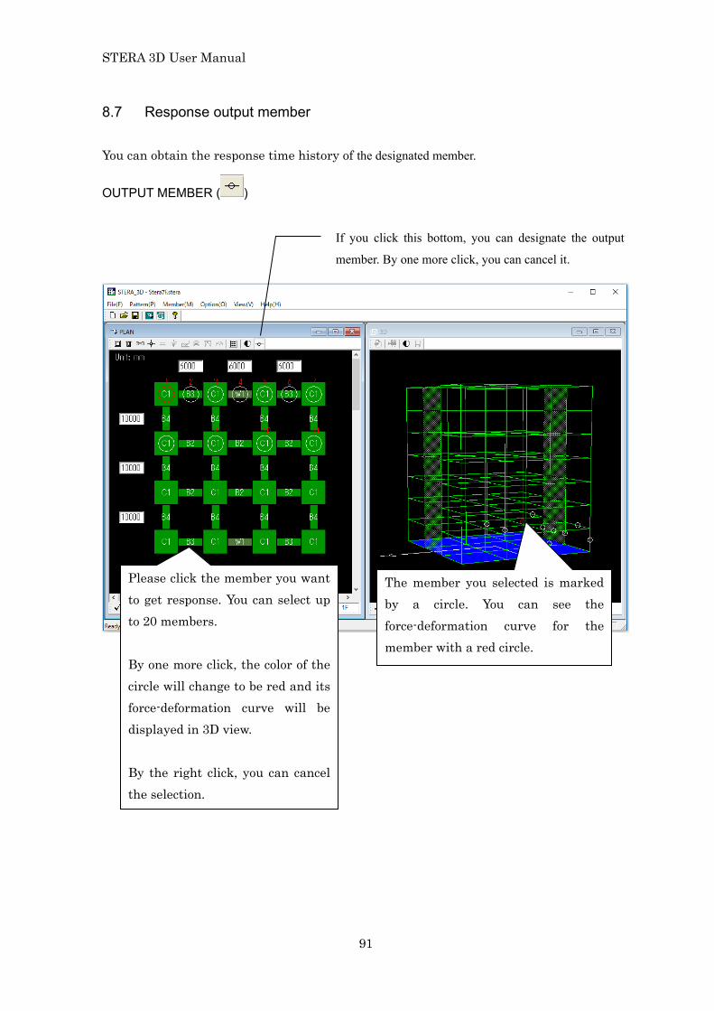
8.7 Response output member You can obtain the response time history of the designated member.
OUTPUT MEMBER ( )
Please click the member you want to get response. You can select up to 20 members. By one more click, the color of the circle will change to be red and its force-deformation curve will be displayed in 3D view. By the right click, you can cancel the selection.
The member you selected is marked by a circle. You can see the force-deformation curve for the member with a red circle.
If you click this bottom, you can designate the output
member. By one more click, you can cancel it.

STERA 3D User Manual
92
8.8 Save Nonlinear Earthquake Response as a Movie File Generally, it takes long time to calculate earthquake response of a building. In this case, you can save the response of the building in a movie file and later you can play the movie to see the response quickly.
1) Record movie [1] On the RESPONSE SETTING DIALOG, please select earthquake input files in the menu “EARTHQUAKE”.
[2] Please push the movie button ( ) and write the file name such as “Movie.txt”.
[3] Automatically the recoding will start.
[3]
[2] [1]

STERA 3D User Manual
93
2) Play movie
[1] On the RESPONSE SETTING DIALOG, please push in the “MOVIE” menu to
select a movie file.
[2] ( ) starts, ( ) pauses and ( ) stops the response.
[1] [2]

STERA 3D User Manual
94
8.9 Change Analysis
[1] On the RESPONSE SETTING DIALOG, you can change the analysis: Mode: Modal Analysis
Static: Nonlinear Static Push-Over Analysis
Dynamic: Earthquake / Vibrator / Wind Response Analysis
Movie: Movie for Nonlinear Earthquake Response Analysis
[1]

STERA 3D User Manual
95
9 Input Earthquake Ground Motion
9.1 Format of input earthquake data file When you prepare an input earthquake file by yourself, please arrange the data format as follows: Order Type Information Comments 1st data (NDATA)
INT Number of data
The number of data for acceleration
2nd data (DT)
REAL Time interval (sec)
3rd data and later
REAL Acceleration (cm/sec2)
Please arrange NDATA data separated by commas or spaces.
The maximum data size of input earthquake (NDATA) is 60,000. ( NDATA < 60,000 ) The ground moves according to the ground displacement are automatically calculated from acceleration data. Example) This is the earthquake data “Kobe 1995_NS.txt” in the “./sample/wave/” folder.
Acceleration data (cm/sec2)
…NDATA …DT (time interval, sec)

STERA 3D User Manual
96
10 Save and Open Files 10.1 Save building data You can save the building data in a file and open it later. The file has an extension “.stera”.
Open file
Save file
New file

STERA 3D User Manual
97
10.2 Save results of analysis in text files You can save the results of modal analysis, nonlinear push-over analysis and nonlinear earthquake response analysis in the text files.. [1] On the RESPONSE SETTING DIALOG, please set the condition of analysis.
[2] Please push the “Save Data” button ( ).
[3] Please select folder to save output text files.
[1]
[2]
[3]

STERA 3D User Manual
98
[4] When you push “OK”, a message window appears to start calculation and save output data to the designated folder.
If you select “Yes”, the analysis starts automatically.

STERA 3D User Manual
99
10.3 Output text files In the designated folder, the following files are automatically created:
data_***
Input data of members and building
max_***
Maximum response of members and building
response_eigen Natural period and mode
response_energy Energy response response_floor01, 02, … Response of 3D rigid floor (6 components) response_member01, 02, … Response of designated members response_structure Response of floors (horizontal components)
beam : Beam bi : Base Isolator column : Column damper : Damper and Nonstructural wall floor : Floor slab ground : Ground spring node : node panel : connection panel spring : External spring structure : Building wall : Wall
STERA 3D User Manual
100
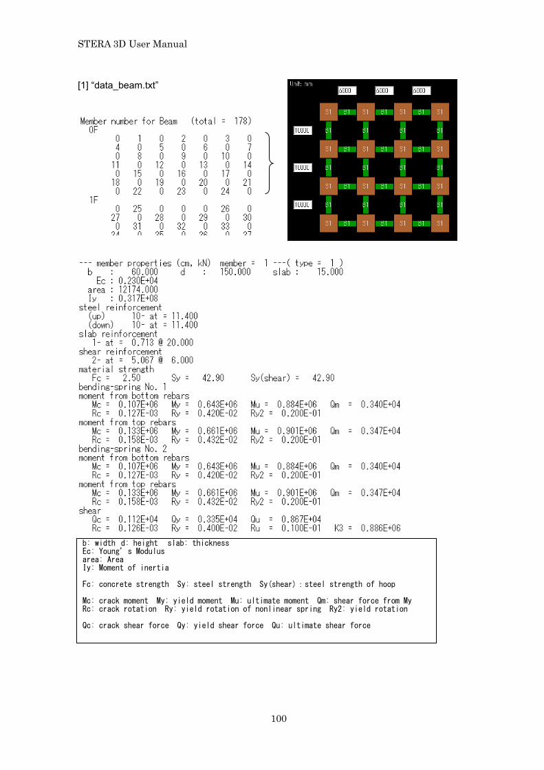
[1] “data_beam.txt”
b: width d: height slab: thickness Ec: Young’s Modulus area: Area Iy: Moment of inertia Fc: concrete strength Sy: steel strength Sy(shear):steel strength of hoop Mc: crack moment My: yield moment Mu: ultimate moment Qm: shear force from My Rc: crack rotation Ry: yield rotation of nonlinear spring Ry2: yield rotation Qc: crack shear force Qy: yield shear force Qu: ultimate shear force

STERA 3D User Manual
101
[2] “data_column.txt”
multi-spring No. 1 x = -0.247E+02 y = -0.247E+02 location of spring Fc: 1st force point Fy: yield force Dc: 1st deformation Dy: yield deformation
Multi-springs

STERA 3D User Manual
102
[3] “data_wall.txt”
ac1: area of column 1 ac2: area of column 2 aw: area of wall ash: area for shear ic1: I(moment of inertia) of column 1 ic1: I of column 2 iw: I of wall
軸ばね(multi-spring)

STERA 3D User Manual
103
[4] “data_ground.txt”
F(foundation), P(pIle), R(real), I(imaginary), K(stiffness), C(damping), h(sway), r(rocking),
x(X-axis), y(Y-axis)
For example
F_RKhx: Foundation Sway Stiffness Spring, Real part, in X-axis
P_IKry: Pile Rocking Stiffness Spring, Imaginary part, around Y-axis
F_Chx: Foundation Sway Damping coefficient, in X-direction
Tx : Building Period in X-axis, Tswx : Sway Period in X-axis, Trky : Rocking Period around Y-axis
Ty : Building Period in Y-axis, Tswy : Sway Period in Y-axis, Trkx : Rocking Period around X-axis
h : Building Damping factor
hx(2) = h + (Tswx/Tx)2 ( hswx + r_hswx ) + (Trky/Tx)2 ( hrky + r_hrky )
hx(3) = h + (Tswx/Tx)3 ( hswx + r_hswx ) + (Trky/Tx)3 ( hrky + r_hrky )
hswx : Sway Damping factor in X-axis, hswy : Sway Damping factor in Y-axis
hrky : Rocking Damping factor around Y-axis, hrkx : Rocking Damping factor around X-axis
r_hswx : Radiation Sway Damping factor in X-axis,
r_hswy : Radiation Sway Damping factor in Y-axis
r_hrky : Radiation Rocking Damping factor around Y-axis,
r_hrkx : Radiation Rocking Damping factor around X-axis,

STERA 3D User Manual
104
[5] “max_beam.txt”
Unit (kN,cm)
Ductility factor is the ratio of the maximum deformation divided by the yield deformation as,
max
y
θµθ
= for member end
max
y
φµφ
= for nonlinear bending spring
ME: Member end A MP: Nonlinear bending spring at end A ME: Member end B MP: Nonlinear bending spring at end B Q: Nonlinear shear spring
yM
cM
cθ yθ
M
θ
M
τ cφ yφ
M
φ
= +
Elastic element Nonlinear bending spring MP
0k 0k ∞≈pk
yM
cM
Member end ME
A B
φ M τ
θ
φ τ
θ M
Q
Um: Ductility factor (= Dm / Dy) (Dm: max disp., Dy: yield disp.) Uh: Cumulative ductility factor (=Eh / QyDy) (Eh: hysteresis energy, Qy: yield force) D.I.: Damage Index (RC: Park and Ang, S: Fatigue)
STERA 3D User Manual
105
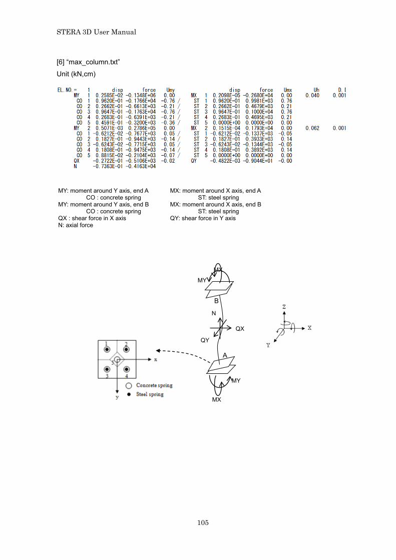
[6] “max_column.txt”
Unit (kN,cm)
MY: moment around Y axis, end A MX: moment around X axis, end A CO : concrete spring ST: steel spring
MY: moment around Y axis, end B MX: moment around X axis, end B CO : concrete spring ST: steel spring
QX : shear force in X axis QY: shear force in Y axis N: axial force
B
MX
MY
A
MX
MY
QX
QY
N

STERA 3D User Manual
106
[7] “max_wall.txt”
Unit (kN,cm)
MXA MXB
MXB MXA
MY
MY
QX QYA QYB
N

STERA 3D User Manual
107
[8] “max_node.txt”
Unit (kN,cm)
node node number <Coordinate>
X X coordinate (cm) Y Y coordinate (cm) Z Z coordinate (cm)
<Maximum nodal displacement> dx displacement in X-direction (cm) dy displacement in Y-direction (cm) dz displacement in Z-direction (cm) rx rotational angle around X-direction ry rotational angle around Y-direction rz rotational angle around Z-direction
STERA 3D User Manual
108
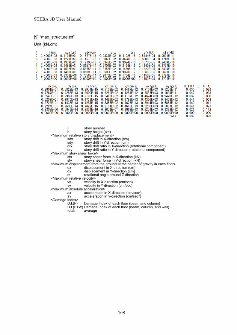
[9] “max_structure.txt”
Unit (kN,cm)
F story number h story height (cm) <Maximum relative story displacement>
sdx story drift in X-direction (cm) sdy story drift in Y-direction (cm) drx story drift ratio in X-direction (rotational component) dry story drift ratio in Y-direction (rotational component)
<Maximum story shear force> sfx story shear force in X-direction (kN) sfy story shear force in Y-direction (kN)
<Maximum displacement from the ground at the center of gravity in each floor> dx displacement in X-direction (cm) dy displacement in Y-direction (cm) rz rotational angle around Z-direction
<Maximum relative velocity> vx velocity in X-direction (cm/sec) vy velocity in Y-direction (cm/sec)
<Maximum absolute acceleration> ax acceleration in X-direction (cm/sec2) ay acceleration in Y-direction (cm/sec2)
<Damage Index> D.I.(F) Damage Index of each floor (beam and column) D.I.(F+W) Damage Index of each floor (beam, column, and wall) total: average

STERA 3D User Manual
109
[10] “response_eigen.txt”
In this file, the results of modal analysis including natural periods, mode vectors, and stimulus functions are saved.
Natural period (sec)
Participation function

STERA 3D User Manual
110
[11] “response_structure.txt”
In case of nonlinear static analysis, the following data are saved for each story.
kstep calculation step in static analysis
< Equivalent 1DOF system> sd displacement (cm) sa acceleration (gal) max drift maximum drift among all stories
<Relative story displacement> F story number
sdx story drift in X-direction (cm) sdy story drift in Y-direction (cm)
<Relative story displacement (shear component)> ssx story drift in X-direction (shear component) (cm) ssy story drift in Y-direction (shear component) (cm)
<Story shear force> sfx story shear force in X-direction (kN) sfy story shear force in Y-direction (kN)
<Relative story displacement (rotational component)> sbx story drift in X-direction (rotational component) sby story drift in Y-direction (rotational component)
<Story moment> smx story moment in X-direction (kNcm) smy story moment in Y-direction (kNcm)
<Displacement from the ground at the center of gravity in each floor> dx displacement in X-direction (cm) dy displacement in Y-direction (cm) rz rotational angle around Z-direction
STERA 3D User Manual
111
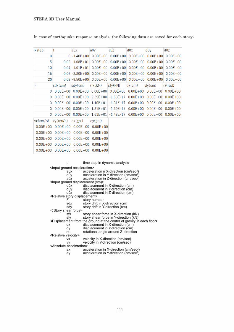
In case of earthquake response analysis, the following data are saved for each story:
t time step in dynamic analysis <Input ground acceleration>
a0x acceleration n X-direction (cm/sec2) a0y acceleration in Y-direction (cm/sec2) a0z acceleration in Z-direction (cm/sec2)
<Input ground displacement (cm)> d0x displacement in X-direction (cm) d0y displacement in Y-direction (cm) d0z displacement in Z-direction (cm)
<Relative story displacement> F story number
sdx story drift in X-direction (cm) sdy story drift in Y-direction (cm)
<Story shear force> sfx story shear force in X-direction (kN) sfy story shear force in Y-direction (kN)
<Displacement from the ground at the center of gravity in each floor> dx displacement in X-direction (cm) dy displacement in Y-direction (cm) rz rotational angle around Z-direction
<Relative velocity> vx velocity in X-direction (cm/sec) vy velocity in Y-direction (cm/sec)
<Absolute acceleration> ax acceleration in X-direction (cm/sec2) ay acceleration in Y-direction (cm/sec2)

STERA 3D User Manual
112
[12] “response_member01.txt …”
In this file, the responses of the designated members are saved.
In case of Beam
Disp. Force. Ductility factor (kN, cm) < Moment > Rya Mya Uya Member end A Rpa Mpa Upa Member end B Ryb Myb Uyb Nonlinear rotational spring at end A Rpb Mpb Upb Nonlinear rotational spring at end B
< Shear Force > Dsz Qsz Usz Nonlinear shear spring
< Axial Force > Dx Nx Axial spring

STERA 3D User Manual
113
In case of Column
~
~ Disp. Force. Ductility factor (kN, cm) < Moment > Rya Mya Uya End A (Bottom) Y-direction Ryb Myb Uyb End B (Bottom) Y-direction Rxa Mxa Uxa End A (Bottom) X-direction Rxb Mxb Uxb End B (Bottom) X-direction < Shear Force > Dsx Qsx Usx Nonlinear shear spring X-direction Dsy Qsy Usy Nonlinear shear spring Y-direction <Axial Force> Dz Nz Axial spring <Torque Force> Rz Tz Torque spring < Multi-spring > C1D(a) C1F(a) C1U(a) End A Concrete Spring 1 C2D(a) C2F(a) C2U(a) End A Concrete Spring 2 C3D(a) C3F(a) C3U(a) End A Concrete Spring 3 C4D(a) C4F(a) C4U(a) End A Concrete Spring 4 C5D(a) C5F(a) C5U(a) End A Concrete Spring 5 S1D(a) S1F(a) S1U(a) End A Steel Spring 1 S2D(a) S2F(a) S2U(a) End A Steel Spring 2 S3D(a) S3F(a) S3U(a) End A Steel Spring 3 S4D(a) S4F(a) S4U(a) End A Steel Spring 4 S5D(a) S5F(a) S5U(a) End A Steel Spring 5 C1D(b) C1F(b) C1U(b) End B Concrete Spring 1 C2D(b) C2F(b) C2U(b) End B Concrete Spring 2 C3D(b) C3F(b) C3U(b) End B Concrete Spring 3 C4D(b) C4F(b) C4U(b) End B Concrete Spring 4 C5D(b) C5F(b) C5U(b) End B Concrete Spring 5 S1D(b) S1F(b) S1U(b) End B Steel Spring 1 S2D(b) S2F(b) S2U(b) End B Steel Spring 2 S3D(b) S3F(b) S3U(b) End B Steel Spring 3 S4D(b) S4F(b) S4U(b) End B Steel Spring 4 S5D(b) S5F(b) S5U(b) End B Steel Spring 5
STERA 3D User Manual
114
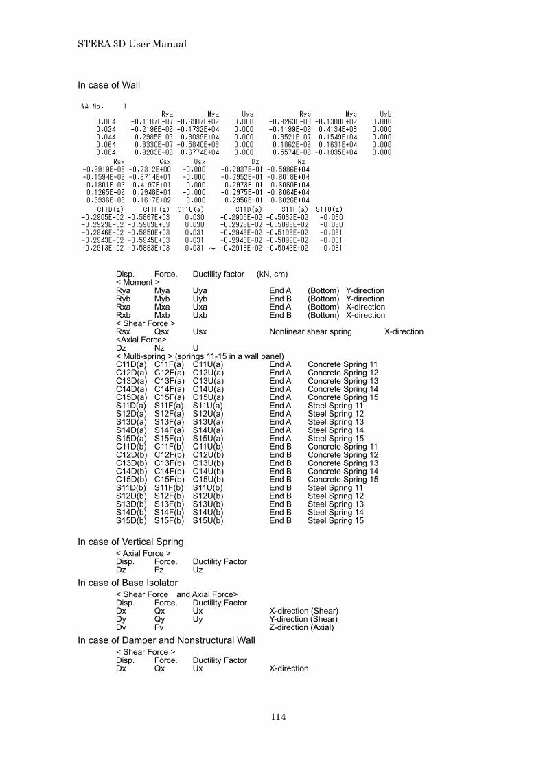
In case of Wall
~
Disp. Force. Ductility factor (kN, cm) < Moment > Rya Mya Uya End A (Bottom) Y-direction Ryb Myb Uyb End B (Bottom) Y-direction Rxa Mxa Uxa End A (Bottom) X-direction Rxb Mxb Uxb End B (Bottom) X-direction < Shear Force > Rsx Qsx Usx Nonlinear shear spring X-direction <Axial Force> Dz Nz U < Multi-spring > (springs 11-15 in a wall panel) C11D(a) C11F(a) C11U(a) End A Concrete Spring 11 C12D(a) C12F(a) C12U(a) End A Concrete Spring 12 C13D(a) C13F(a) C13U(a) End A Concrete Spring 13 C14D(a) C14F(a) C14U(a) End A Concrete Spring 14 C15D(a) C15F(a) C15U(a) End A Concrete Spring 15 S11D(a) S11F(a) S11U(a) End A Steel Spring 11 S12D(a) S12F(a) S12U(a) End A Steel Spring 12 S13D(a) S13F(a) S13U(a) End A Steel Spring 13 S14D(a) S14F(a) S14U(a) End A Steel Spring 14 S15D(a) S15F(a) S15U(a) End A Steel Spring 15 C11D(b) C11F(b) C11U(b) End B Concrete Spring 11 C12D(b) C12F(b) C12U(b) End B Concrete Spring 12 C13D(b) C13F(b) C13U(b) End B Concrete Spring 13 C14D(b) C14F(b) C14U(b) End B Concrete Spring 14 C15D(b) C15F(b) C15U(b) End B Concrete Spring 15 S11D(b) S11F(b) S11U(b) End B Steel Spring 11 S12D(b) S12F(b) S12U(b) End B Steel Spring 12 S13D(b) S13F(b) S13U(b) End B Steel Spring 13 S14D(b) S14F(b) S14U(b) End B Steel Spring 14 S15D(b) S15F(b) S15U(b) End B Steel Spring 15
In case of Vertical Spring < Axial Force > Disp. Force. Ductility Factor Dz Fz Uz
In case of Base Isolator < Shear Force and Axial Force> Disp. Force. Ductility Factor Dx Qx Ux X-direction (Shear) Dy Qy Uy Y-direction (Shear) Dv Fv Z-direction (Axial)
In case of Damper and Nonstructural Wall < Shear Force > Disp. Force. Ductility Factor Dx Qx Ux X-direction
STERA 3D User Manual
115
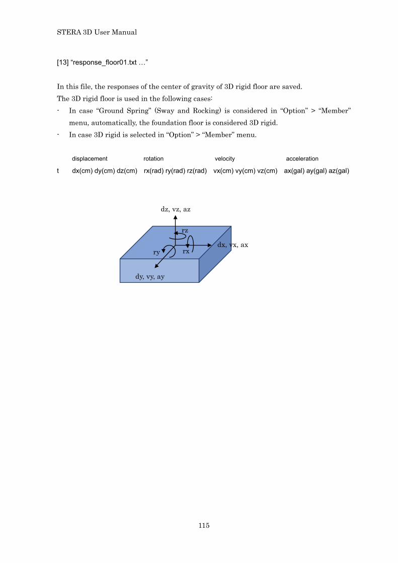
[13] “response_floor01.txt …”
In this file, the responses of the center of gravity of 3D rigid floor are saved. The 3D rigid floor is used in the following cases: - In case “Ground Spring” (Sway and Rocking) is considered in “Option” > “Member”
menu, automatically, the foundation floor is considered 3D rigid. - In case 3D rigid is selected in “Option” > “Member” menu. displacement rotation velocity acceleration
t dx(cm) dy(cm) dz(cm) rx(rad) ry(rad) rz(rad) vx(cm) vy(cm) vz(cm) ax(gal) ay(gal) az(gal)
dz, vz, az
dx, vx, ax
dy, vy, ay
rx ry
rz

STERA 3D User Manual
116
11 Continuous Analysis
When you push the “Save Data” button ( ) during Dynamic
Please select condition of continuous analysis from the menu: 0 None No continuous analysis (default) 1 /------ Initial Initial analysis
(save building status after the analysis) 2 ---/--- Successive Successive analysis
(read previous building status, then save it after the analysis) 3 ------/ Final Final analysis
(read building status) In continuous analysis, it is recommended to change the folder to save output files in each analysis, since all output files will be overwritten.
STERA_3D input_all.dat
STERA_3D input_all.dat input_all.dat
STERA_3D input_all.dat
STERA 3D User Manual
117
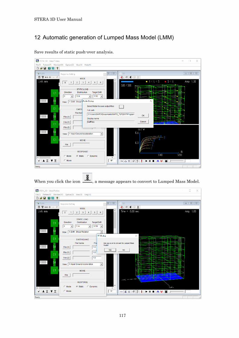
12 Automatic generation of Lumped Mass Model (LMM) Save results of static push-over analysis.
When you click the icon , a message appears to convert to Lumped Mass Model.

STERA 3D User Manual
118
If you anser YES, an equivalent LMM will be automatically created.
If you conduct static push-over analysis, you will see that the force-deformation relationship of each story is modeled as a tri-linear hysteresis model.

STERA 3D User Manual
119
- The element model of each story is “Wall with direct input” with shear and bending springs. The hysteresis of each spring is modeled as non-linear tri-linear model.
- The element type number is “W2” for 1F, “W3” for 2F, …, etc. - The restrained freedom automatically set as 2467 (X-direction only). - Floor Slab of each story is automatically set as 3D Rigid.
In “./output” folder, “LMM_comparison.txt” and “LMM_wall_direct.txt” are automatically created.

STERA 3D User Manual
120
“LMM_comparison.txt” includes the data of story shear force and story displacement relationships both for frame model and LMM under static push-over analysis.
“LMM_wall_direct.txt” includes the parameters of hysteresis for shear and bending springs of Wall (direct input) model as described in 6.2 using the same format of “Data_wall_direct.txt” by [Export] button.
Please refer “Technical Manual” for the detail for how to obtain the equivalent tri-linear skelton.

STERA 3D User Manual
121
13 Command line execution After you save the results of analysis as described in 10.2, there are text files automatically generated in the folder of STERA_3D as shown below:
where inputdata.txt Input data of structure inputwave_x.txt Ground acceleration data in x (horizontal)-direction (see 9.1) inputwave_y.txt Ground acceleration data in y (horizontal)-direction (see 9.1) inputwave_z.txt Ground acceleration data in z (vertical)-direction (see 9.1) also load_distribution.txt Horizontal load distribution in static analysis (see 7.2) out_comparison.txt Comparizon of Q-D between frame and LMM (see 11) out_parameter.txt Q-D parameters of LMM (see 11) weight_distribution.txt Weight distribution in a floor node (see 7.1)
When you execute “Response.exe”, the analysis will start using the following files in “input” folder as input files:
inputdata.txt inputwave_x.txt inputwave_y.txt inputwave_z.txt
That is, you can execulte the program by command line without using STERA_3D.

STERA 3D User Manual
122
From the command prompt,
For example, let’s make a batch file (test.bat) to replace the earthquake ground acceleration data as Earth_NS.txt Earth_EW.txt Earth_UD.txt test.bat
If you double click “test.bat”, the new anlaysis will start using new input waves.
Execute “Response.exe”
@echo off
copy .¥Earth_NS.txt .¥input¥inputwave_x.txt
copy .¥Earth_EW.txt .¥input¥inputwave_y.txt
copy .¥Earth_UD.txt .¥input¥inputwave_z.txt
Response