Embed Size (px)
Citation preview

C-279
Accessories
Cables ·····································································C-284Flexible Couplings ···················································C-288Clean Dampers ·······················································C-293Mounting Brackets for Stepping Motors ··················C-295DIN Rail Mounting Plate ··········································C-298
C-279
Step
pin
gM
oto
rs
Mo
tor &
Driver P
ackages
Clo
sed L
oo
p A
AC
Inp
ut
DC
Inp
ut
5-Ph
ase Micro
stepA
C In
pu
tD
C In
pu
t5-P
hase F
ull/H
alfD
C In
pu
tA
C In
pu
tD
C In
pu
t2-P
hase F
ull/H
alfwith Indexer
Driver
Co
ntro
llers
AS
AS PLU
SA
SCRK
CFK2
CSKU
MK
CSK
PK/PV
UI2120G
EMP4
01
EMP4
02
SG8030J
SMK
AccessoriesPM
C
Low-SpeedSynchronous
Motors
IntroductionPK
with
En
cod
er
2-Phase Stepping Motors
Before Usinga Stepping
Motor
with
ou
tE
nco
der
C-280
Step
pin
gM
oto
rs
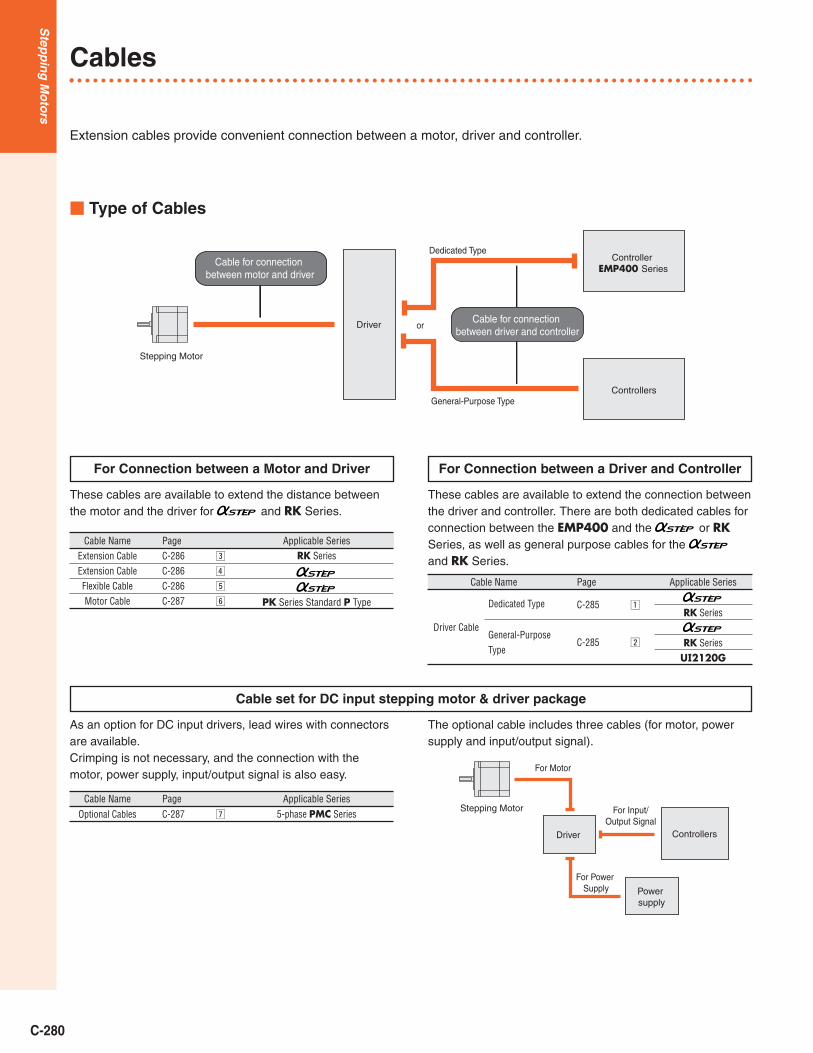
Cables
� Type of Cables
These cables are available to extend the connection betweenthe driver and controller. There are both dedicated cables forconnection between the EMP400 and the or RKSeries, as well as general purpose cables for the and RK Series.
These cables are available to extend the distance betweenthe motor and the driver for and RK Series.
As an option for DC input drivers, lead wires with connectorsare available.Crimping is not necessary, and the connection with themotor, power supply, input/output signal is also easy.
The optional cable includes three cables (for motor, powersupply and input/output signal).
For Connection between a Driver and ControllerFor Connection between a Motor and Driver
Cable set for DC input stepping motor & driver package
Extension cables provide convenient connection between a motor, driver and controller.
Cable NameExtension CableExtension CableFlexible CableMotor Cable
PageC-286C-286C-286C-287
c
v
b
n
Applicable SeriesRK Series
PK Series Standard P Type
Cable Name
Optional Cables
Page
C-287 m
Applicable Series
5-phase PMC Series
Cable Name
Driver Cable
Page
General-Purpose Type
C-285 x
Applicable Series
RK Series
RK SeriesUI2120G
Cable for connection between motor and driver
Stepping Motor
Driver Cable for connection between driver and controller
Controller EMP400 Series
Controllers
Dedicated Type
General-Purpose Type
or
Stepping Motor
Driver Controllers
For Motor
For Power Supply Power
supply
For Input/Output Signal
zC-285Dedicated Type

C-281
Driver CablesThese cables are convenient for connecting and RK series drivers to controllers. General-PurposeType and Dedicated Type (equipped with the connectorfor the EMP series controller) are available.
z Dedicated TypeOne end of the cable is a half-pitchconnector that snaps into the driverfor and RK series. The otherend of the cable is equipped with theconnector for the EMP400 seriescontroller.
Note:Note that as the length of the pulse signal line increases, the maximumtransmission frequency decrease. (➝Technical Reference Page F-36)
� Product Line� For
� For RK Series
� Dimensions Scale 1/4, Unit = inch (mm)
� For
� For RK Series
ModelCC01EMP4CC02EMP4
Applicable Series
AS, ASC Series
Length L ft. (m)3.3 (1)6.6 (2)
ModelCC01EMP5CC02EMP5
Length L ft. (m)3.3 (1)6.6 (2)
x General-Purpose TypeThis is a ribbon cable equippedwith, at one end of the cable, thehalf-pitch connector that snapsinto the driver for , RKseries and UI2120G.
Note:Note that as the length of the pulse signal line increases, the maximumtransmission frequency decrease. (➝Technical Reference Page F-36)● Install a connector that matches the controller you are using to the other end of
the cable.
� Product Line
� Dimensions Scale 1/4, Unit = inch (mm)
� For Conductor: AWG28
� For (AS PLUS), RK Series and UI2120GConductor: AWG28
Model
CC20D1-1
Applicable Series
AS PLUSRK SeriesUI2120G
Length L ft. (m)
3.3 (1)
1.71
(43.
46)
L0.5 (12.7)
1.46
(37.
11)
L
0.28 (7)Controller side
Sensor side
Driver side
3.54 (90)
�0.
24(�
6)
�0.
24(�
6)
1.54 (39)
0.5 (12.7)1.54 (39)
Sensor side
L
Driver side
1.31
(33.
3)
0.5 (12.7)
L
L 1.54 (39)
0.5(12.7)
1.46
(37.
11)
Controller side
3.54 (90)
1.54 (39)0.39 (10)
3.54 (90)
0.79(20)
0.79(20)
0.39 (10)
0.28 (7)
0.28 (7)Control for driver side
�0.
24(�
6)�
0.22
(�5.
7)�
0.24
(�6)
L
Pitch 0.05 (1.27)
Laminate0.50(12.7)
1.71
(43.
46)
0.39�0.12 (10�3)
0.39�0.12
(10�3)
0.39�0.12 (10�3)
(60�
15)
2.36
�0.
59
�0.295(�7.5)
Shield
0�0.39
0�10 )
1.18 (30
Controller sideDriver side
L
Pitch 0.05 (1.27)
Laminate0.50(12.7)
1.31
(33.
3)
0.39�0.12 (10�3)
0.39�0.12
(10�3)
0.39�0.12 (10�3)
(60�
15)
2.36
�0.
59
�0.252(�6.4)
Shield
0�0.39
0�10 )
1.18 (30
Controller sideDriver side
CC36D1-1CC36D2-1
CC20D2-1
3.3 (1)6.6 (2)
6.6 (2)
Note:● The alarm clear signal of the AS and ASC series cannot be used with the
EMP400 series controller.
Step
pin
gM
oto
rs
Mo
tor &
Driver P
ackages
Clo
sed L
oo
p A
AC
Inp
ut
DC
Inp
ut
5-Ph
ase Micro
stepA
C In
pu
tD
C In
pu
t5-P
hase F
ull/H
alfD
C In
pu
tA
C In
pu
tD
C In
pu
t2-P
hase F
ull/H
alfwith Indexer
Driver
Co
ntro
llers
AS
AS PLU
SA
SCRK
CFK2
CSKU
MK
CSK
PK/PV
UI2120G
EMP4
01
EMP4
02
SG8030J
SMK
AccessoriesPM
C
Low-SpeedSynchronous
Motors
IntroductionPK
with
En
cod
er
2-Phase Stepping Motors
Before Usinga Stepping
Motor
with
ou
tE
nco
der

C-282
Step
pin
gM
oto
rs
c Extension Cable (For RK Series)These extension cables are usedbetween RK series motors anddedicated drivers. They come inthree lengths: 16.4 feet (5 m), 32.8feet (10 m), and 65.6 feet (20 m).
● Conductor size: AWG22● Finished outer diameter: �0.28 inch (�7.2mm)● Cable rating: 221˚F (105°C)● Outer casing: oil-resistant, heat-resistant, non-migrating vinylNote:These extension cables are only for the RK Series. Do not use them on otherstepping motor & driver packages.
v Extension Cable (For )These extension cables are convenientwhen using the steppingmotor and driver more than 1.31 feet(0.4 m) apart from each other.It’s not necessary when the followingproducts are used where the distance
between the driver and the motor is 1.31 ft. (0.4 m) or less.● AS, AS PLUS, ASC Series w/o electromagnetic brake● AS, AS PLUS, ASC Series electromagnetic brake type [Motor Frame Size:
1.65 inch (42 mm)]
� Product Line� For Standard � For with Electromagnetic Brake
Note:● Electromagnetic Brake models must use an extension cable for an
Electromagnetic Brake. But motor frame size �1.65 in. (�42 mm) model canuse a standard extension cable for the Electromagnetic Brake.
✽ ASC Series can not use extension cable with 49.2 ft. (15 m), 65.6 ft. (20 m)length.
� Dimensions Scale 1/4, Unit = inch (mm)
For Standard
For with Electromagnetic Brake
L
Motor Side Driver Side
0.47(12)
�0.31 (�8)
0.96
( 24.
3)
1.18
( 30)
0.87
( 22.
2)
0.46 (11.6)0.57 (14.5)
b Flexible Cable (For )This flexible cable is used between
motors and dedicated drivers.We recommend this cable when themotor is installed on a moving sectionand the cable is repeatedly bent andextended.It is not necessary when the following
products are used where the distance between the driver andthe motor is 1.31 ft. (0.4 m) or less.● AS Series, AS PLUS, ASC Series w/o electromagnetic brake● AS Series, AS PLUS, ASC Series electromagnetic brake type [Motor Frame
Size: 1.65 inch (42 mm)]
� Product Line� For Standard � For with Electromagnetic Brake
Note:● Electromagnetic Brake models must use an extension cable for an
Electromagnetic Brake. But motor frame size �1.65 in. (�42 mm) model canuse a standard extension cable for the Electromagnetic Brake.
� Dimensions Scale 1/4, Unit = inch (mm)
For Standard
For with Electromagnetic Brake
● When only the extension between motor and driver is needed, use an extensioncable.
L
Motor Side Driver Side
0.47(12)
�0.37 (�9.5)
0.96
( 24.
3)
1.18
( 30)
0.87
( 22.
2)
0.46 (11.6)0.57 (14.5)
1.18
(30)
0.96
(24.3
)
0.87
(22.2
)
0.57 (14.5)L0.47 (12)0.46 (11.6)
�0.31 (�8)
Motor Side Driver SideElectromagnetic Brake Leads 2.4 inch (60mm) Length (Orange/Black, Gray AWG24)
ModelCC05PK5CC10PK5CC20PK5
Length L ft. (m)16.4 (5)
32.8 (10)65.6 (20)
Conductors
5
ModelCC01AIPCC02AIPCC03AIPCC05AIPCC07AIPCC10AIPCC15AIPCC20AIP
Length L feet (m)3.3 (1)6.6 (2)9.8 (3)
16.4 (5)23 (7)
32.8 (10)49.2 (15)✽
65.6 (20)✽
ModelCC01SARCC02SARCC03SARCC05SARCC07SARCC10SAR
Length L feet (m)3.3 (1)6.6 (2)9.8 (3)
16.4 (5)23 (7)
32.8 (10)
ModelCC01SARM2CC02SARM2CC03SARM2CC05SARM2CC07SARM2CC10SARM2
Length L feet (m)3.3 (1)6.6 (2)9.8 (3)
16.4 (5)23 (7)
32.8 (10)
ModelCC01AIPMCC02AIPMCC03AIPMCC05AIPMCC07AIPMCC10AIPMCC15AIPMCC20AIPM
Length L feet (m)3.3 (1)6.6 (2)9.8 (3)
16.4 (5)23 (7)
32.8 (10)49.2 (15)✽
65.6 (20)✽
1.18
(30)
0.96
(24.3
)
0.87
(22.2
)
0.57 (14.5)L0.47 (12)0.46 (11.6)
�0.37 (�9.5)
Motor Side Driver SideElectromagnetic Brake Leads 2.4 inch (60mm) Length (Orange, Gray AWG22)
C-283
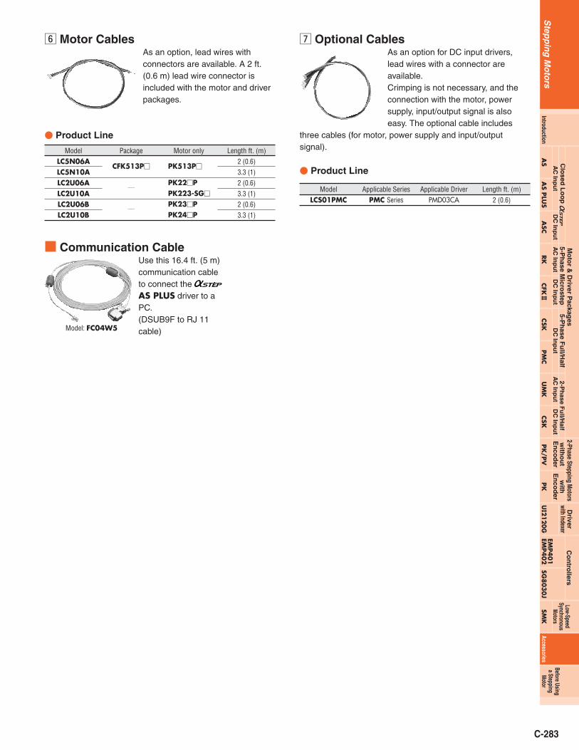
m Optional CablesAs an option for DC input drivers,lead wires with a connector areavailable.Crimping is not necessary, and theconnection with the motor, powersupply, input/output signal is alsoeasy. The optional cable includes
three cables (for motor, power supply and input/outputsignal).
� Product Line
n Motor CablesAs an option, lead wires withconnectors are available. A 2 ft.(0.6 m) lead wire connector isincluded with the motor and driverpackages.
� Product Line
ModelLCS01PMC
Applicable SeriesPMC Series
Applicable DriverPMD03CA
Length ft. (m)2 (0.6)
ModelLC5N06ALC5N10ALC2U06ALC2U10ALC2U06BLC2U10B
Package
CFK513P�
/
/
Motor only
PK513P�
PK22�PPK223-SG�
PK23�PPK24�P
Length ft. (m)2 (0.6)3.3 (1)2 (0.6)3.3 (1)2 (0.6)3.3 (1)
Step
pin
gM
oto
rs
Mo
tor &
Driver P
ackages
Clo
sed L
oo
p A
AC
Inp
ut
DC
Inp
ut
5-Ph
ase Micro
stepA
C In
pu
tD
C In
pu
t5-P
hase F
ull/H
alfD
C In
pu
tA
C In
pu
tD
C In
pu
t2-P
hase F
ull/H
alfwith Indexer
Driver
Co
ntro
llers
AS
AS PLU
SA
SCRK
CFK2
CSKU
MK
CSK
PK/PV
UI2120G
EMP4
01
EMP4
02
SG8030J
SMK
AccessoriesPM
C
Low-SpeedSynchronous
Motors
IntroductionPK
with
En
cod
er
2-Phase Stepping Motors
Before Usinga Stepping
Motor
with
ou
tE
nco
der
� Communication CableUse this 16.4 ft. (5 m)communication cableto connect the AS PLUS driver to aPC.(DSUB9F to RJ 11cable)Model: FC04W5

C-284
Step
pin
gM
oto
rs
Flexible Couplings
MC Motor Couplings
� Selecting an MC CouplingOnce you have decided on a motor and the shaft diameter ofthe equipment to be connected, determine the proper flexiblecoupling to use. Oriental Motor flexible couplings areavailable in external diameter sizes that provide the strengthrequired for the motor torque.All motor shaft diameters of stepping motor units areavailable with the exception of geared models.There are three broad categories for the shaft diameter onthe equipment to be connected based on the motor shaftdiameter (except for some clamp types).
� Features● No backlash.● Plate springs formed of slits reliably absorb eccentricity,
declination and end play.● Torsional rigidity is high, responsiveness excellent.● Characteristics are the same in forward and reverse.● Maintenance free (excellent resistance to oil and
chemicals).● Aluminum alloy construction.● Standardized shaft hole sizes for motor shafts and
driven shafts of different diameters.
� When the motor is a RK566AA [outer diameter of shaft:0.315 inch (8 mm) and the shaft diameter of the equipment tobe connected to the motor is 0.25 inch (6.35 mm)] useMC2508F04C.
� When the motor is a RK5913AA [outer diameter of shaft:0.5512 inch (14 mm)] and the shaft diameter of the equipmentto be connected to the motor is 0.5 inch (12.7 mm)] useMC5014F08C.
MC coupling can be selected using with motor sizing calculation result (➝PageF-2). Select a coupling which has rated torque bigger than motor requiredtorque. In this way, smaller coupling may be able to use.
C04F04F25MC� Product Number Code
MC Couplings
Connection MethodC: Clamp Type
Shaft Hole SizeBlank: Metric SizeF: Inch Size
Shaft Hole SizeBlank: Metric SizeF: Inch Size
Inner Diameter
Inner Diameter
Outer Diameter of Coupling
C04F0825MCInternal Diameter
Examples
Internal Diameter
MC12
MC16
MC20
MC25
MC32
MC40
MC50
�0.1969(�5)
�0.1969(�5)
�0.1969(�5)
�0.25(�6.35)�0.312
(�7.937)�0.315
(�8)�0.25
(�6.35)�0.312
(�7.937)�0.315
(�8)�0.5
(�12.7)�0.5512
(�14)�0.5
(�12.7)�0.5512
(�14)
/
AS46A(M), ASC34AK,ASC36AK, ASC46A(M)K
/
/
/
/
/
/
AS66A(M), AS69A(M)ASC66A(M)K
/
AS98A(M), AS911A
/
/
RK543, CFK53�, CFK543, CSK543, PMC3�
RK544, RK545, CFK544, CFK545, CSK544, CSK545
/
/
CFK564, CFK566CSK564, CSK566
RK564, RK566
/
CFK569,CSK569
RK569
CFK596, CFK599, CSK596, CSK599
RK596, RK599
CFK5913, CSK5913
RK5913
UMK243, CSK243
UMK244, CSK244
UMK245, CSK245
UMK264, CSK264UMK266, CSK266
/
/
UMK268, CSK268
/
/
UMK296, UMK299, CSK296, CSK299
/
UMK2913, CSK2913
/
TypeShaft Diameter
in. (mm)A 5-Phase Stepping Motors
2-Phase SteppingMotor Package
Low-SpeedSynchronous
Motors
Driven Shaft Diameter in. (mm)0.1875(4.763)
0.25 (6.35)
0.3125(7.938)
0.375 (9.525)
0.5 (12.7)
0.625(15.875)
PK22�P
PK233P, PK243
PK235P, PK244,PK245
PK264
/
/
PK266, PK268PV264, PV266
/
/
PK296
/
PK299, PK2913
/
SMK014
/
SMK237
/
/
/
/
/
SMK5100SMK5160
/
/
�
�
�
�
�
�
�
�
�
�
�
�
�
�
�
�
�
�
�
�
�
�
�
�
�
�
�
�
�
�
2-Phase SteppingMotors

C-285
� Dimensions Unit = inch (mm)
� MC12-C, MC16-C, MC20-C, MC25-C, MC32-C � MC40-C, MC50-C
� Specifications
MC2005F03C
MC2005F04C
MC2005F05C
MC2008F04C
MC2008F05C
MC25F04F04C
MC25F04F05C
MC25F04F06C
MC2508F04C
MC2508F05C
MC2508F06C
MC32F04F04C
MC32F04F05C
MC32F04F06C
MC3208F04C
MC3208F05C
MC3208F06C
MC40F08F06C
MC40F08F08C
MC40F08F10C
MC4014F06C
MC4014F08C
MC4014F10C
MC50F08F08C
MC50F08F10C
MC5014F08C
MC5014F10C
0.79
(20)
0.98
(25)
1.26
(32)
1.57
(40)
1.97
(50)
1.02
(26)
1.22
(31)
1.61
(41)
2.2
(56)
2.8
(71)
0.3
(7.5)
0.33
(8.5)
0.47
(12)
0.59
(15)
0.71
(18)
M2.5
M3
M4
M5
M6
2
2
2
2
2
71
(0.5)
142
(1)
280
(2)
710
(5)
1420
(10)
0.67
(19)
1.2
(34)
2.6
(75)
5.6
(160)
12
(330)
0.06
(11�10�7)
0.175
(32�10�7)
0.66
(120�10�7)
2.2
(400�10�7)
6.6
(1200�10�7)
750
(85)
2000
(230)
3100
(360)
6700
(760)
26000
(3000)
0.0039
(0.1)
0.0059
(0.15)
0.0059
(0.15)
0.0078
(0.2)
0.0078
(0.2)
�0.015
(�0.4)
�0.019
(�0.5)
�0.019
(�0.5)
�0.019
(�0.5)
�0.019
(�0.5)
MC1205F03C
MC1605F03C
MC1605F04C
0.472(12)
Model OuterDiameter�A in.(mm)
Dimensions
0.73(18.5)
0.63(16)
0.91(23)
LengthW
in.(mm)
�0.1969(�5 )
�0.1969(�5 )
�0.1969(�5 )
�0.3150(�8 )
�0.2500(�6.35 )
�0.3150(�8 )
�0.2500(�6.35 )
�0.3150(�8 )
�0.5000(�12.7 )
�0.5512(�14 )
�0.5000(�12.7 )
�0.5512(�14 )� 0.027
0
� 0.00110
� 0.0270
� 0.00110
� 0.0270
� 0.00110
� 0.0270
� 0.00110
� 0.0220
� 0.00090
� 0.0220
� 0.00090
� 0.0220
� 0.00090
� 0.0220
� 0.00090
� 0.0220
� 0.00090
� 0.0180
� 0.00070
� 0.0180
� 0.00070
� 0.0180
� 0.00070
Shaft HoleDiameter
d1 in. (mm)
Shaft HoleDiameter
d2 in. (mm)
0.2(5)
L
in.(mm)
M2
ScrewUsed
M
28(0.2)
RatedTorqueoz-in(N·m)
0.14(4)
0.0055(1�10�7)
280(32)
0.0039(0.1)
�0.011(�0.3)2
0.26(6.5) M2.5 42
(0.3)0.32(9)
0.022(4�10�7)
390(45)
0.0039(0.1)
�0.015(�0.4)2
Weightoz.(g)
PermissibleEnd Playin. (mm)
PermissibleDeclination
degrees
PermissibleEccentricityin. (mm)
Static TorsionSpring Constant
lb-in/rad(N·m/rad)
Inertiaoz-in2
(kg·m2)
�0.1875(�4.763 )
�0.1875(�4.763 )
�0.2500(�6.35 )
�0.1875(�4.763 )
�0.2500(�6.35 )
�0.3125(�7.938 )�0.2500(�6.35 )
�0.3125(�7.938 )�0.2500(�6.35 )
�0.3125(�7.938 )�0.3750(�9.525 )�0.2500(�6.35 )
�0.3125(�7.938 )�0.3750(�9.525 )�0.2500(�6.35 )
�0.3125(�7.938 )�0.3750(�9.525 )�0.2500(�6.35 )
�0.3125(�7.938 )�0.3750(�9.525 )�0.3750(�9.525 )�0.5000(�12.7 )
�0.6250(�15.875 )�0.3750(�9.525 )�0.5000(�12.7 )
�0.6250(�15.875 )�0.5000
(�12.7 )�0.6250(�15.875 )�0.5000
(�12.7 )�0.6250(�15.875 )� 0.027
0
� 0.00110
� 0.0270
� 0.00110
� 0.0270
� 0.00110
� 0.0270
� 0.00110
� 0.0270
� 0.00110
� 0.0270
� 0.00110
� 0.0220
� 0.00090
� 0.0270
� 0.00110
� 0.0270
� 0.00110
� 0.0220
� 0.00090
� 0.0220
� 0.00090
� 0.0220
� 0.00090
� 0.0220
� 0.00090
� 0.0220
� 0.00090
� 0.0220
� 0.00090
� 0.0220
� 0.00090
� 0.0220
� 0.00090
� 0.0220
� 0.00090
� 0.0220
� 0.00090
� 0.0220
� 0.00090
� 0.0220
� 0.00090
� 0.0220
� 0.00090
� 0.0220
� 0.00090
� 0.0220
� 0.00090
� 0.0220
� 0.00090
� 0.0220
� 0.00090
� 0.0180
� 0.00070
� 0.0220
� 0.00090
� 0.0180
� 0.00070
� 0.0180
� 0.00070
M
�A
�d2
�d1
L L
W
�d2
W
�A
�d1
L L
M
Step
pin
gM
oto
rs
Mo
tor &
Driver P
ackages
Clo
sed L
oo
p A
AC
Inp
ut
DC
Inp
ut
5-Ph
ase Micro
stepA
C In
pu
tD
C In
pu
t5-P
hase F
ull/H
alfD
C In
pu
tA
C In
pu
tD
C In
pu
t2-P
hase F
ull/H
alfwith Indexer
Driver
Co
ntro
llers
AS
AS PLU
SA
SCRK
CFK2
CSKU
MK
CSK
PK/PV
UI2120G
EMP4
01
EMP4
02
SG8030J
SMK
AccessoriesPM
C
Low-SpeedSynchronous
Motors
IntroductionPK
with
En
cod
er
2-Phase Stepping Motors
Before Usinga Stepping
Motor
with
ou
tE
nco
der

C-286
Step
pin
gM
oto
rs
MCL Geared Motor Couplings
� Selecting an MCL CouplingOnce you have decided on a motor and the shaft diameter ofthe equipment to be connected to it, determine the properflexible coupling to use. Oriental Motor flexible coupling areavailable external diameter in sizes that provide the strengthrequired for the motor torque.
These flexible couplings are clamp types and connect gearedstepping motors to other shafts. Select the coupling to matchthe motor.
� Features● Couplings come with shaft holes and have standardized
combinations of different diameter shaft holes.● Characteristics are the same for clockwise and
counterclockwise rotation.● Oil-resistant and electrically insulated couplings are
available.● Aluminum alloy construction.● The shaft being driven is not damaged, since shafts are
joined by clamping.● Easy installation due to separating hub and sleeve design.
When the motor is CSK264ATA-SG3.6 [outer diameter of
shaft: 0.3125 inch (7.938 mm)] and the axis diameter of the
equipment to be connected to the motor is 0.375 inch (9.525
mm), use MCL30F05F06.
08F06F40MCL� Product Number Code
MCL Couplings
F: Inch Size
Shaft Hole SizeBlank: Metric SizeF: Inch Size
Inner Diameter d2
Inner Diameter d1
Outer Diameter of Coupling
06F05F30MCLInternal Diameter d2
Examples
Internal Diameter d1
MCL20
MCL30
MCL40
PMC33-MG�
—
—
—
TypeShaft Diameter
in. (mm)5-Phase Stepping Motors
CSK243-SG�, PK223-SG�
PK243-SG�
—
CSK264-SG�
PK264-SG�
PK296-SG�
2-Phase Stepping Motors
SMK216-GN /2GN�KA
SMK550-GN /5GN�KA
SMK0A-�A
—
Low-SpeedSynchronous
Motor
Driven Shaft Diameter in. (mm)
0.1875(4.763)
� � �
�
� �
�� �
0.25 (6.35)
0.3125(7.938)
0.375 (9.525)
0.5 (12.7)
0.625(15.875)
�0.1968(�5)
�0.25(�6.35)
�0.3125(�7.938)
�0.5(�12.7)
C-287
Clamp ScrewM2.5 �2 Places
Set ScrewM3 �2 Places
0.26(6.5)
0.39(10)
1.14 (29)
0.20 (5)
0.39(10)
0.2 (5)
0.02(0.5)
0.02(0.5)
0.31(8)
�0.
79(�
20)
�d2
�d1
Clamp ScrewM4�2 Places
Set Screw M4�2 Places
0.39(10)
1.71 (43.5)
0.31(8)
0.31(8)
0.63 (16) 0.63 (16)
0.03(0.75)
0.03(0.75)
0.39(10)
�1.
18 (�
30)
�d2
�d1
0.49 (12.5) 0.49 (12.5)
0.98 (25) 0.98 (25)
2.52 (64)
0.04 (1)
0.47 (12)
0.04 (1)
�1.
57 (�
40) Set Screw M4
Clamp Screw M6
Set Screw M4
Clamp Screw M6
0.51
(13)
�d1
�d2
Set Screw M4
Set Screw M4
Clamp Screw M6
0.49 (12.5)0.49 (12.5)
0.98 (25)0.98 (25)
2.52 (64)
0.04 (1)
0.47 (12)
0.04 (1)
0.51
(13)
Clamp Screw M6
�1.
57 (�
40)
�d2
�d1
0.1575�0.0017
(4�0.043)0
0
0.46
5�0.
004
(11.8
�0.1
)0 0
1°
1°
1°
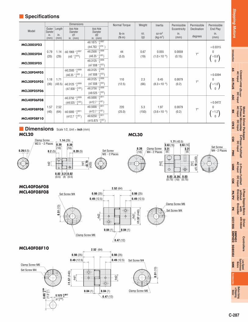
MCL2005F03
MCL2005F04
MCL2005F05
MCL30F04F05
MCL30F05F05
MCL30F05F06
MCL40F06F08
MCL40F08F08
MCL40F08F10
�0.0315
0
(�0.8)0
�0.0394
0
(�1.0)0
�0.0472
0
(�1.2)0
0.0059
(0.15)
0.0079
(0.2)
0.0079
(0.2)
0.055
(1.0�10�6)
0.45
(8.3�10�6)
1.97
(3.6�10�5)
0.67
(19)
2.3
(66)
5.3
(150)
44
(5.0)
110
(12.5)
220
(25.0)
1.14
(29)
1.71
(43.5)
2.52
(64)
Axis HoleDiameter
d1in. (mm)
�0.1969(�5 )
�0.2500(�6.35 )
�0.3125(�7.938 )
�0.3750(�9.525 )
�0.5000(�12.7 )� 0.027
0
� 0.00110
� 0.0220
� 0.00090
� 0.0220
� 0.00090
� 0.0220
� 0.00090
� 0.0180
� 0.00070
Axis HoleDiameter
d2in. (mm)
Dimensions
0.79
(20)
1.18
(30)
1.57
(40)
PermissibleDeclination
degrees
Model
PermissibleEnd Play
in.(mm)
PermissibleEccentricity
in.(mm)
Inertia
oz-in2
(kg·m2)
Weight
oz.(g)
Normal Torque
lb-in(N·m)
Length
in.(mm)
OuterDiameter
in.(mm)
� Specifications
� Dimensions Scale 1/2, Unit = inch (mm)
MCL20 MCL30
MCL40F08F10
MCL40F06F08MCL40F08F08
�0.1875(�4.763 )�0.2500
(�6.35 )�0.3125(�7.938 )
�0.3125(�7.938 )
�0.3125(�7.938 )
�0.3750(�9.525 )
�0.5000(�12.7 )
�0.5000(�12.7 )
�0.6250(�15.875 )� 0.027
0
� 0.00110
� 0.0270
� 0.00110
� 0.0270
� 0.00110
� 0.0220
� 0.00090
� 0.0220
� 0.00090
� 0.0220
� 0.00090
� 0.0220
� 0.00090
� 0.0220
� 0.00090
� 0.0180
� 0.00070
Step
pin
gM
oto
rs
Mo
tor &
Driver P
ackages
Clo
sed L
oo
p A
AC
Inp
ut
DC
Inp
ut
5-Ph
ase Micro
stepA
C In
pu
tD
C In
pu
t5-P
hase F
ull/H
alfD
C In
pu
tA
C In
pu
tD
C In
pu
t2-P
hase F
ull/H
alfwith Indexer
Driver
Co
ntro
llers
AS
AS PLU
SA
SCRK
CFK2
CSKU
MK
CSK
PK/PV
UI2120G
EMP4
01
EMP4
02
SG8030J
SMK
AccessoriesPM
C
Low-SpeedSynchronous
Motors
IntroductionPK
with
En
cod
er
2-Phase Stepping Motors
Before Usinga Stepping
Motor
with
ou
tE
nco
der

C-288
Step
pin
gM
oto
rs
� Mounting to a ShaftClamp couplings use the binding force of the screw tocompress the shaft hole diameter and thereby fasten thecoupling to the shaft. This does not damage the shaft and iseasy to mount and remove. The following table shows thescrew binding torque. We recommend use of a torquewrench to fasten the coupling.
� Alignment AdjustmentFlexible couplings tolerate misalignment of the axis centerand transfer rotational angle and torque, but producevibration when the permissible value for misalignment isexceeded. This can dramatically shorten the coupling’sservice life. This requires alignment adjustment.Misalignment of the axis center includes eccentricity (parallelerror of both centers), declination (angular error of bothcenters) and end play (shaft movement in the axial direction).To keep misalignment within the permissible value, alwayscheck and adjust the alignment. To increase the service lifeof the coupling, we recommend keeping misalignment tobelow 1/3 of the permissible value.
Notes: ● When misalignment exceeds the permissible value or excessive torque is
applied, the coupling's shape will deform, and service life is shortened.● When the coupling emits a metallic sound during operation, stop operation
immediately and ensure there is no misalignment, axis interference or loosescrews.
● When load changes are large, paint the coupling set screw with an adhesive toprevent the coupling screw from loosening or substitute a coupling one sizelarger.
Straight Edge
Eccentricity
End Play
Declination
Tightening Torqueoz-in
( N·m ) Tightening Torque of oz-inkey press screw for ( N·m )MCL coupling
MC12-C
71
(0.5 )
/
MC16-CMC20-CMCL20
142
(1)
99
(0.7)
MC25-C
210
(1.5)
/
MC32-CMCL30
350
(2.5)
280
(1.7)
MC40-C
560
(4)
/
MC50-C
1130
(8)
/
MCL40
1700
(12)
2400
(17)

C-289
Clean Dampers
� Features● Since there is no frictional dust as in conventional magnetic
dampers, it can be used in environments where higherdegrees of cleanness is needed.
● Excellent vibration absorption● The doughnut-shaped internal inertia body and silicon gel
absorb vibration. This feature enables a stable dampingeffect.
● High reliability● It holds up well in harsh environments and changes little
with age because the silicon gel and plastic case used areheat resistant.
� Product Line
Ambient Temperature: �4°F��176°F (�20°C��80°C)✽ Insert the motor case length into the � of the model name. The character of A, B and M which show the shaft type and electromagnetic brake type are omitted.
Mechanical dampers suppress stepping motorvibration and improve high-speed performance. Aninertial body and silicon gel are hermetically sealed ina plastic case. This offers the following advantagesover conventional magnetic dampers.
Ring
Silicon Gel
Inertia Ring
CaseShaft Hole
VEXT
A
VEXT
A
VEXTA
VEXTA
D4CL-5.0F
D6CL-6.3F
D6CL-8.0F
D9CL-12.7F
D9CL-14F
0.186(34�10�7)
0.77(140�10�7)
0.77(140�10�7)
4.8(870�10�7)
4.8(870�10�7)
ModelInertia
oz-in2 (kg·m2)
0.053 (24)
0.14 (62)
0.13 (61)
0.23 (105)
0.23 (105)
Weight lb. (g)
RK54�, RK54�-T, RK54�-N,RK54�-HCFK53�, CFK54�
CSK54�, CSK543-TG�
PMC3�, PMC33-MG�,PMC33-HG�
RK56�, RK56�-T, RK56�-N,RK56�-HCFK56�, CFK56�H
CFK59�, CFK59�HCSK59�
RK59�
RK59�-TRK59�-NRK59�-H
UMK24�, UMK24�MCSK24�, CSK24�M, CSK243-SG�
PK22�PPK23�PPK24�PPK24�, PK24�MPK223-SG�, PK243-SG�
UMK26�
UMK26�MCSK26�
CSK26�MCSK264-SG�
PK26�
PK26�MPK264-SG�
PV264, 266, 267
CSK29�
PK29�,PK296-SG
Compatible Motors
5-Phase 2-Phase
Clean Damper Structure
� Installation of the Clean DamperPoint the mounting screws of theclean damper toward the motorcase, fasten to the shaft andtighten the damper's mountingscrews (2 places) with ahexagonal wrench to secure it tothe shaft.
Notes:● There are mounting screws with hexagonal holes in two damper locations, so
tighten them both before running the motor.● The damper rotates at the same speed as the motor shaft, so do not touch it
while the motor is running.
� Dimensions ➝ page C-294
Step
pin
gM
oto
rs
Mo
tor &
Driver P
ackages
Clo
sed L
oo
p A
AC
Inp
ut
DC
Inp
ut
5-Ph
ase Micro
stepA
C In
pu
tD
C In
pu
t5-P
hase F
ull/H
alfD
C In
pu
tA
C In
pu
tD
C In
pu
t2-P
hase F
ull/H
alfwith Indexer
Driver
Co
ntro
llers
AS
AS PLU
SA
SCRK
CFK2
CSKU
MK
CSK
PK/PV
UI2120G
EMP4
01
EMP4
02
SG8030J
SMK
AccessoriesPM
C
Low-SpeedSynchronous
Motors
IntroductionPK
with
En
cod
er
2-Phase Stepping Motors
Before Usinga Stepping
Motor
with
ou
tE
nco
der

C-290
Step
pin
gM
oto
rs
� Dimensions Unit = inch (mm)
�d1
�d1
�B
CD
�A
2-E
+0.00070.1969 0+0.018(5 0 )
+0.00090.2500 0+0.022(6.35 0 )
+0.00090.3150 0+0.022(8 0 )
+0.00110.500 0+0.027(12.7 0 )
+0.00110.5512 0+0.027(14 0 )
Model d1
�1.42 �0.02
(�36 �0.5)
�1.75 �0.02
(�44.5 �0.5)
�3.13 �0.02
(�79.5 �0.5)
A
�0.51 �0.02
(�13 �0.5)
�0.79 �0.02
(�20 �0.5)
�1.02 �0.02
(�26 �0.5)
B
0.354 �0.012
(9 �0.3)
0.591 �0.012
(15 �0.3)
0.433 �0.012
(11 �0.3)
C
M3
2 Places
M4
2 Places
M4
2 Places
E
0.591 �0.012
(15 �0.5)
0.87 �0.02
(22 �0.5)
0.75 �0.02
(19 �0.5)
D
D4CL-5.0F
D6CL-6.3F
D6CL-8.0F
D9CL-12.7F
D9CL-14F

C-291
� Product LineThere are 10 types of mounting brackets for stepping motors.� Standard Type, Standard P Type, High-Speed Type,
High-Resolution Type, High Inertia Type (PV Series)
Material: Aluminum die cast
● Insert the motor case length in the � of the model name. The character of A and B which show the shaft type are omitted (except for Low Speed Synchronous Motor).
● The mounting bracket base is built with holes large enough to allow for alignment adjustments in the horizontal direction.(Adjustable range: Approximately 0.24 inch [6 mm])
● These mounting brackets can be perfectly fitted to the pilot of the stepping motors. (except for PAL0PA)Notes:● These mounting brackets are for stepping motors only. They cannot be used with compact AC motors.● They cannot be used with geared stepping motors.
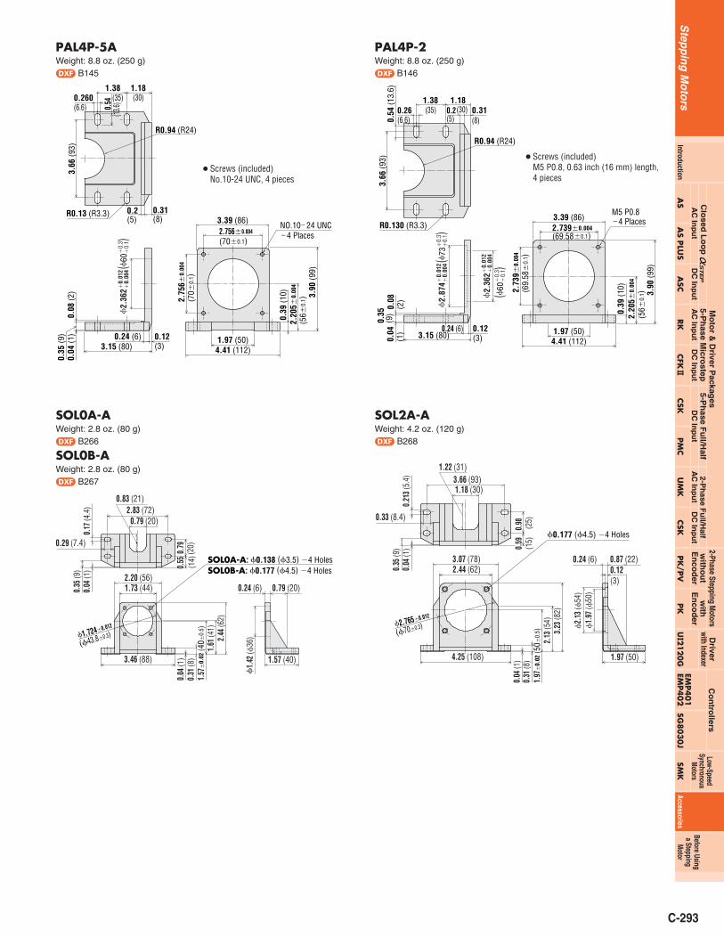
Mounting Brackets for Stepping Motors
Mounting brackets are convenient for installingmaintaining proper alignment between the motor shaftand the load.
PAL0PA
PAF0P
PAL2P-5A
PAL2P-2
PAL4P-5A
PAL4P-2
/
AS46A, AS46MASC46AK, ASC46MKAS66A, AS69AAS66M, AS69MASC66AK, ASC66MK
/
AS98A, AS98MAS911A
/
Mounting
Bracket
Models
Applicable Motor Type
A
CSK54�
CFK54�
RK54�
RK56�
CSK56�
CFK56�, CFK56�H
/
RK59�
CSK59�, CFK59�H
/
5-Phase Stepping Motors
UMK24�, UMK24�MCSK24�, CSK24�MPK24�, PK24�M
PK24�P
/
UMK26�, UMK26�MCSK26�, CSK26�MPK26�, PK26�MPV26�
/
CSK29�
PK29�
2-Phase Stepping Motors
SMK014A-A SMK014MA-A
/
SMK237A-A
/
SMK5100A-AASMK5160A-AA
Low-SpeedSynchronous Motors
� Geared TypeMaterial: Aluminum die cast
● Insert the gear ratio in the � of the model name.The character of A and B which show the shaft type and the length of the motor case are partly omitted.
● The mounting bracket base is built with holes large enough to allow for alignment adjustments in the horizontal direction.● When mounting, use the screws included with the geared motor. (except for )Note:● These mounting brackets are for geared stepping motors only. They cannot be used with compact AC motors or stepping motors with gearheads.
SOL0A-A
SOL0B-A
SOL2A-A
SOL5B-A
/
AS46-T�
ASC46-T�
AS66-T�
ASC66-T�
AS98-T�
Mounting BracketModels
Applicable Motor Type
/
RK543-T�
CSK543-T�
RK564-T�
CSK564-T�
RK596-T�
5-Phase Stepping Motors
CSK243-SG�
PK243-SG�
/
CSK264-SG�
PK264-SG�
PK296-SG�
2-Phase Stepping Motors
SMK0A-�
/
/
/
SMK
Step
pin
gM
oto
rs
Mo
tor &
Driver P
ackages
Clo
sed L
oo
p A
AC
Inp
ut
DC
Inp
ut
5-Ph
ase Micro
stepA
C In
pu
tD
C In
pu
t5-P
hase F
ull/H
alfD
C In
pu
tA
C In
pu
tD
C In
pu
t2-P
hase F
ull/H
alfwith Indexer
Driver
Co
ntro
llers
AS
AS PLU
SA
SCRK
CFK2
CSKU
MK
CSK
PK/PV
UI2120G
EMP4
01
EMP4
02
SG8030J
SMK
AccessoriesPM
C
Low-SpeedSynchronous
Motors
IntroductionPK
with
En
cod
er
2-Phase Stepping Motors
Before Usinga Stepping
Motor
with
ou
tE
nco
der

C-292
Step
pin
gM
oto
rs
� Mounting the Motorz PAL2P-�, PAL4P-�
� Use the screws provided to secure the motorto the mounting bracket.
� Attach the motor from the direction shown by the arrow (B).
x PAL0PASOL0�, SOL2�, SOL5�
� Use the screws provided to secure the motorto PAL0PA.
� Attach the motor from the direction shown by the arrow (B).
c PAF0P
� Use the screws provided to secure the motorto PAF0P.
� Motor can be attached from either side (A,B).
� Dimensions Unit = inch (mm)
PAL0PAWeight: 1.24 oz. (35 g)d B139
● Screws (included)No.4-40 UNC, 4 pieces
● Screws (included)M3 P0.5, 0.28 inch (7 mm) length, 4 pieces
PAF0PWeight: 1.06 oz. (30 g)d B140
�0.138 (�3.5)�4 Holes
0.91
0.31
(8
)
0.91(23)
0.59(15)
0.22(5.5)
1.770.12 (3) 0.08
(2)
1.65 (42)
2.36 (60)
0.24
(6)
1.97
(50)
0.94
(24)
1.89
(48)
1.14
2�0.
012
(29�
0.3)
(31�0.3)
(45)
(3.5)
(23)
R0.07 (R1.75)
R0.47 (R12)
1.22
0�0.
012
(31�
0.3 )
1.220�0.012
�0.
020
�0.
50
)�
1.48
(�37
.6
0.14
A
A'Cross Section AA'
�0.138 (�3.5)�4 HolesR0.0
7
(1.75
)
1.65
(42)
0.12(3
)0.2
8 (7)
0.02
(0.5)
(� 2
2 0
)
�0.5
0.28 (7)1.22�0.012
(31�0.3)
2.13 (54)2.6 (66)
1.22
�0.
012
(31�
0.3)
0.31 (8)
0.14
(3.5)
0.47(12)
1.65 (42) 0.47(12)
� 0
.87
�0.
020
BB
A
B
● Screws (included)No.8-32 UNC, 4 pieces
PAL2P-5AWeight: 3.9 oz. (110 g)d B143
NO.8�32 UNC�4 Places
0.30
(7.5
)1.
575�
0.00
4
(40�
0.1 )
2.76
(70)
1.26(32)
3.27 (83)
2.44 (62)
0.16 (4) 0.08(2)0.
04
0.24
2.68
(68)
0.17(4.4)
0.43
(11)
0.98 0.79(20)
0.14
0.26
(6.5
)0.
06
1.969�0.004
(50�0.1)
2.17 (55)
1.96
9�0.
004
(50�
0.1)
(25)
(3.5) (6)
(1.5
)(1
)
R0.09 (R2.2)
R0.59 (R15)
�0.
012
�0.
004
�0.
3�
0.1 )
�1.
417
(�36
PAL2P-2Weight: 3.9 oz. (110 g)d B144
M4 P0.7�4 Places
0.30
(7.5
)1.
575�
0.00
4
(40�
0.1)
2.76
(70)
1.26(32)
3.27 (83)
1.856�0.004
2.44 (62)
0.16 (4) 0.08(2)0.
042.
68 (6
8)0.
26(6
.5) 0
.06
2.17 (55)
1.85
6�0.
004
0.43
(11)
0.170.98(25)0.14
0.790.24(6)(4.4) (3.5)
(20)
(1.5
)(1
)
(47.14�0.1)
(47.
14�
0.1)
R0.09 (R2.2)
R0.59 (R15)
�0.
012
�0.
004
�0.
3�
0.1 )
�1.
500
(�38
.1
● Screws (included)M4 P0.7, 0.47 inch (12 mm)length, 4 pieces
C-293
● Screws (included)No.10-24 UNC, 4 pieces
PAL4P-5AWeight: 8.8 oz. (250 g)d B145
0.35
(9)
NO.10�24 UNC�4 Places
0.260(6.6)
1.38 1.18
0.04
(1) 0.24 (6)
0.08
(2)
3.15 (80)1.97 (50)4.41 (112)
0.39
(10)
2.20
5�0.
004
(56�
0.1) 3.
90 (9
9)
2.756�0.004
(70�0.1)
3.39 (86)
0.54
0.12(3)
3.66
(93)
0.2(5)
0.31(8)
(35) (30)
(13.6)
2.75
6�0.
004
(70�
0.1)
R0.13 (R3.3)
R0.94 (R24)�
0.01
2�
0.00
4�
0.3
�0.
1 )�
2.36
2 (�
60
PAL4P-2Weight: 8.8 oz. (250 g)d B146
0.26(6.6)
1.38 1.18
0.35
(9)
0.04
(1) 0.12
(3)0.24 (6)
0.08
(2)
3.15 (80) 1.97 (50)4.41 (112)
0.39
(10)
2.20
5�0.
004
(56�
0.1) 3.
90 (9
9)
3.39 (86)
0.54
(13.
6)3.
66 (9
3)
0.2(5)
0.31(8)
(35) (30)
2.73
9�0.
004
(69.
58�
0.1)
2.739�0.004
(69.58�0.1)
M5 P0.8�4 PlacesR0.130 (R3.3)
R0.94 (R24)
�0.
012
�0.
004
�0.
3�
0.1 )
�2.
874
(�73
�0.
012
�0.
004
�0.
3�
0.1 )
�2.
362
(�60
● Screws (included)M5 P0.8, 0.63 inch (16 mm) length,4 pieces
SOL2A-AWeight: 4.2 oz. (120 g)d B268
1.18 (30)3.66 (93)
1.22 (31)
0.21
3 (5
.4)
0.33 (8.4)
0.04
(1)
0.35
(9)
0.98 (25)
0.59
(15)
�0.177 (�4.5) �4 Holes
0.24 (6) 0.87 (22)0.12(3)
�1.
97 (�
50)
�2.
13 (�
54)
1.97 (50)
3.07 (78)2.44 (62)
4.25 (108)
0.04
(1)
0.31
(8)
1.97
�0.
02 (5
0�0.
5 )2.
13 (5
4)3.
23 (8
2)
(�70�0.3)�2.765�0.012
SOL0A-AWeight: 2.8 oz. (80 g)d B266
SOL0B-AWeight: 2.8 oz. (80 g)d B267
0.79
(20)
0.55
(14)
0.17
(4.4
)0.
04 (1
)0.
35 (9
)
0.04
(1)
0.31
(8)
1.57
�0.
02 (4
0�0.
5 )1.
61 (4
1)2.
44 (6
2)
�1.
42 (�
36)
(�43.8�0.3)
0.83 (21)2.83 (72)
0.79 (20)
0.29 (7.4)
2.20 (56)1.73 (44)
�1.724�0.012
3.46 (88)
SOL0A-A: �0.138 (�3.5) �4 HolesSOL0B-A: �0.177 (�4.5) �4 Holes
1.57 (40)
0.24 (6) 0.79 (20)
Step
pin
gM
oto
rs
Mo
tor &
Driver P
ackages
Clo
sed L
oo
p A
AC
Inp
ut
DC
Inp
ut
5-Ph
ase Micro
stepA
C In
pu
tD
C In
pu
t5-P
hase F
ull/H
alfD
C In
pu
tA
C In
pu
tD
C In
pu
t2-P
hase F
ull/H
alfwith Indexer
Driver
Co
ntro
llers
AS
AS PLU
SA
SCRK
CFK2
CSKU
MK
CSK
PK/PV
UI2120G
EMP4
01
EMP4
02
SG8030J
SMK
AccessoriesPM
C
Low-SpeedSynchronous
Motors
IntroductionPK
with
En
cod
er
2-Phase Stepping Motors
Before Usinga Stepping
Motor
with
ou
tE
nco
der
C-294
Step
pin
gM
oto
rs
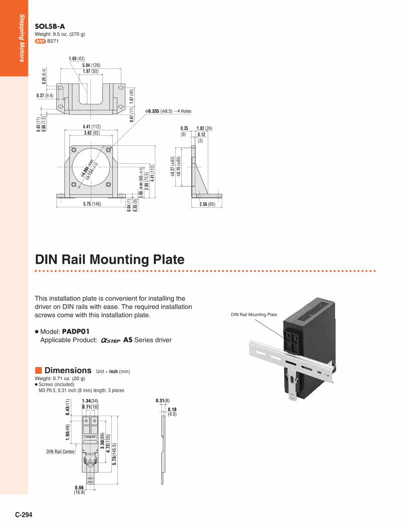
SOL5B-AWeight: 9.5 oz. (270 g)d B271
0.37 (9.4)
0.06
(1.5
)0.
43 (1
1)
4.41 (112)3.62 (92) 0.12
(3)
�4.094
�0.0
12
(�10
4�0.
3)
5.04 (128)1.97 (50)
1.69 (43)
0.25
(6.4
)
1.57
(40)
0.67
(17) �0.335 (�8.5) �4 Holes
5.75 (146)
0.04
(1)
0.35
(9) 2.
60�
0.02
(66�
0.5 )
2.89
(73.
5)4.
41 (1
12)
�3.
15 (�
80)
�3.
27 (�
83)
2.56 (65)
0.35(9)
1.02 (26)
DIN Rail Mounting Plate
This installation plate is convenient for installing thedriver on DIN rails with ease. The required installationscrews come with this installation plate.
● Model: PADP01Applicable Product: AS Series driver
DIN Rail Mounting Plate
� Dimensions Unit = inch (mm)Weight: 0.71 oz. (20 g)● Screws (included)
M3 P0.5, 0.31 inch (8 mm) length, 3 pieces
DIN Rail Center
1.34(34)
1.93
(49)
3.50
(89)
0.71(18)
0.43
(11)
4.72
(120
)
0.66(16.8)
5.73
(145
.5)
0.31(8)
0.18(4.5)