Embed Size (px)
Citation preview

STEERING
C
D
E
SECTION ST A
B
STEERING SYSTEM
F
H
I
J
K
L
M
T
N
O
P
CONTENTS
S
SYSTEM DESCRIPTION .............................. 3
HEATED STEERING WHEEL ............................. 3System Diagram ........................................................3System Description ...................................................3Component Parts Location ........................................3Component Description .............................................4
WIRING DIAGRAM ....................................... 5
HEATED STEERING WHEEL ............................. 5Wiring Diagram .........................................................5
SYMPTOM DIAGNOSIS ............................... 8
NOISE, VIBRATION AND HARSHNESS (NVH) TROUBLESHOOTING ............................. 8
NVH Troubleshooting Chart ......................................8
PRECAUTION ............................................... 9
PRECAUTIONS ................................................... 9Precaution for Supplemental Restraint System (SRS) "AIR BAG" and "SEAT BELT PRE-TEN-SIONER" ...................................................................9Service Notice or Precautions ...................................9
PREPARATION ...........................................10
PREPARATION ..................................................10Special Service Tool ...............................................10Commercial Service Tool ........................................11
PERIODIC MAINTENANCE .........................12
POWER STEERING FLUID ...............................12Inspection ................................................................12Draining ...................................................................12Refilling ...................................................................12
STEERING WHEEL ............................................14Inspection ................................................................14
POWER STEERING OIL PUMP .......................16Inspection ................................................................16
REMOVAL AND INSTALLATION ...............17
STEERING WHEEL ..........................................17Removal and Installation .........................................17
TILT MOTOR .....................................................18Exploded View .........................................................18Removal and Installation .........................................18
TELESCOPIC MOTOR .....................................20Exploded View .........................................................20Removal and Installation .........................................20
STEERING COLUMN ........................................22Exploded View .........................................................22Removal and Installation .........................................23
STEERING GEAR AND LINKAGE ...................26Exploded View .........................................................26Removal and Installation .........................................26
POWER STEERING OIL PUMP .......................28Exploded View .........................................................28Removal and Installation .........................................28
HYDRAULIC LINE ............................................29Exploded View .........................................................29Removal and Installation .........................................30
UNIT DISASSEMBLY AND ASSEMBLY ....31
STEERING COLUMN ........................................31Disassembly and Assembly .....................................31
STEERING GEAR AND LINKAGE ...................33Exploded View .........................................................33Disassembly ............................................................33Inspection ................................................................33Assembly .................................................................34
ST-1Revision: August 2012 2013 Maxima

POWER STEERING OIL PUMP ........................ 36Disassembly and Assembly .................................... 36
SERVICE DATA AND SPECIFICATIONS (SDS) ........................................................... 37
SERVICE DATA AND SPECIFICATIONS (SDS) .................................................................. 37
Steering Wheel ....................................................... 37Steering Angle ........................................................ 37Steering Column ..................................................... 37Steering Gear .......................................................... 38Oil Pump ................................................................. 39Steering Fluid .......................................................... 39
ST-2Revision: August 2012 2013 Maxima
HEATED STEERING WHEEL
C
D
E
F
H
I
J
K
L
M
A
B
T
N
O
P
< SYSTEM DESCRIPTION >
S
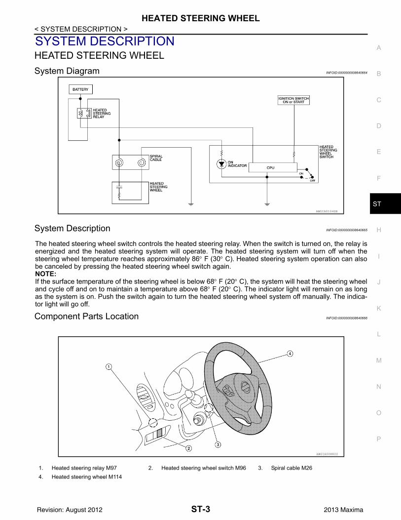
SYSTEM DESCRIPTIONHEATED STEERING WHEELSystem Diagram INFOID:0000000008640664
System Description INFOID:0000000008640665
The heated steering wheel switch controls the heated steering relay. When the switch is turned on, the relay isenergized and the heated steering system will operate. The heated steering system will turn off when thesteering wheel temperature reaches approximately 86° F (30° C). Heated steering system operation can alsobe canceled by pressing the heated steering wheel switch again.NOTE:If the surface temperature of the steering wheel is below 68° F (20° C), the system will heat the steering wheeland cycle off and on to maintain a temperature above 68° F (20° C). The indicator light will remain on as longas the system is on. Push the switch again to turn the heated steering wheel system off manually. The indica-tor light will go off.
Component Parts Location INFOID:0000000008640666
AWGIA0104GB
1. Heated steering relay M97 2. Heated steering wheel switch M96 3. Spiral cable M264. Heated steering wheel M114
AWGIA0088ZZ
ST-3Revision: August 2012 2013 Maxima

HEATED STEERING WHEEL
< SYSTEM DESCRIPTION >Component Description INFOID:0000000008640667Heated steering wheel switch • Controls the heated steering relay and operates the heated steering wheel system.• Turns the indicator lamp ON when the system is activated.
Heated steering relay • Operates the heated steering system with the control signal from the heated steering wheel switch.
Heated steering wheel • Heats the heating element with the power supplied from the heated steering relay.
ST-4Revision: August 2012 2013 Maxima

HEATED STEERING WHEEL
C
D
E
F
H
I
J
K
L
M
A
B
T
N
O
P
< WIRING DIAGRAM >
S
WIRING DIAGRAMHEATED STEERING WHEELWiring Diagram INFOID:0000000008640668
ABGWA0034GB
ST-5Revision: August 2012 2013 Maxima

HEATED STEERING WHEEL
< WIRING DIAGRAM >ABGIA0009GB
ST-6Revision: August 2012 2013 Maxima

HEATED STEERING WHEEL
C
D
E
F
H
I
J
K
L
M
A
B
T
N
O
P
< WIRING DIAGRAM >
S
ABGIA0010GB
ST-7Revision: August 2012 2013 Maxima

NOISE, VIBRATION AND HARSHNESS (NVH) TROUBLESHOOTING
< SYMPTOM DIAGNOSIS >SYMPTOM DIAGNOSISNOISE, VIBRATION AND HARSHNESS (NVH) TROUBLESHOOTINGNVH Troubleshooting Chart INFOID:0000000008640669
Use chart below to help you find the cause of the symptom. If necessary, repair or replace these parts.
×: Applicable
Reference pageS
T-12
—
ST-
33
ST-
33
ST-
33
ST-
12
ST-
14
ST-
33
EM
-14,
"Che
ckin
g D
rive
Bel
ts"
— —
ST-
26
ST-
31
ST-
23
ST-
26
Ref
er to
FA
X-4
, "N
VH
Tro
uble
shoo
ting
Cha
rt"
Ref
er to
FS
U-2
, "N
VH
Tro
uble
shoo
ting
Cha
rt"
Ref
er to
WT-
55, "
NV
H T
roub
lesh
ootin
g C
hart"
Ref
er to
WT-
55, "
NVH
Tro
uble
shoo
ting
Cha
rt"
Ref
er to
FA
X-4
, "N
VH
Tro
uble
shoo
ting
Cha
rt"
Ref
er to
BR
-6, "
NVH
Tro
uble
shoo
ting
Cha
rt"
Possible cause and SUSPECTED PARTS
Flui
d le
vel
Air i
n hy
drau
lic s
yste
m
Out
er s
ocke
t bal
l joi
nt s
win
ging
forc
e
Out
er s
ocke
t bal
l joi
nt ro
tatin
g to
rque
Out
er s
ocke
t bal
l joi
nt e
nd p
lay
Stee
ring
fluid
leak
age
Stee
ring
whe
el p
lay
Stee
ring
gear
rack
slid
ing
forc
e
Driv
e be
lt lo
osen
ess
Impr
oper
ste
erin
g w
heel
Impr
oper
inst
alla
tion
or lo
osen
ess
of ti
lt lo
ck le
ver
Mou
ntin
g ru
bber
det
erio
ratio
n
Stee
ring
colu
mn
defo
rmat
ion
or d
amag
e
Impr
oper
inst
alla
tion
or lo
osen
ess
of s
teer
ing
colu
mn
Stee
ring
linka
ge lo
osen
ess
WH
EE
L H
UB
AX
LE a
nd S
US
PE
NS
ION
TIR
ES
RO
AD
WH
EE
L
DR
IVE
SH
AFT
BR
AK
ES
Symptom Steering
Noise × × × × × × × × × × × × × × ×
Shake × × × × × × ×
Vibration × × × × × × ×
Shimmy × × × × × × ×
Shudder × × × × × ×
ST-8Revision: August 2012 2013 Maxima
PRECAUTIONS
C
D
E
F
H
I
J
K
L
M
A
B
T
N
O
P
< PRECAUTION >
S
PRECAUTIONPRECAUTIONSPrecaution for Supplemental Restraint System (SRS) "AIR BAG" and "SEAT BELT PRE-TENSIONER" INFOID:0000000008772904
The Supplemental Restraint System such as “AIR BAG” and “SEAT BELT PRE-TENSIONER”, used alongwith a front seat belt, helps to reduce the risk or severity of injury to the driver and front passenger for certaintypes of collision. This system includes seat belt switch inputs and dual stage front air bag modules. The SRSsystem uses the seat belt switches to determine the front air bag deployment, and may only deploy one frontair bag, depending on the severity of a collision and whether the front occupants are belted or unbelted.Information necessary to service the system safely is included in the SR and SB section of this Service Man-ual.WARNING:• To avoid rendering the SRS inoperative, which could increase the risk of personal injury or death in
the event of a collision which would result in air bag inflation, all maintenance must be performed byan authorized NISSAN/INFINITI dealer.
• Improper maintenance, including incorrect removal and installation of the SRS, can lead to personalinjury caused by unintentional activation of the system. For removal of Spiral Cable and Air BagModule, see the SR section.
• Do not use electrical test equipment on any circuit related to the SRS unless instructed to in thisService Manual. SRS wiring harnesses can be identified by yellow and/or orange harnesses or har-ness connectors.
PRECAUTIONS WHEN USING POWER TOOLS (AIR OR ELECTRIC) AND HAMMERSWARNING:• When working near the Airbag Diagnosis Sensor Unit or other Airbag System sensors with the Igni-
tion ON or engine running, DO NOT use air or electric power tools or strike near the sensor(s) with ahammer. Heavy vibration could activate the sensor(s) and deploy the air bag(s), possibly causingserious injury.
• When using air or electric power tools or hammers, always switch the Ignition OFF, disconnect thebattery and wait at least 3 minutes before performing any service.
Service Notice or Precautions INFOID:0000000008640671
• In case of removing steering gear assembly, make the final tightening with grounded and unloaded vehiclecondition, and then check wheel alignment.
• Observe the following precautions when disassembling.- Before disassembly, thoroughly clean the outside of the unit.- Disassembly should be done in a clean work area. It is important to prevent the internal parts from becoming
contaminated by dirt or other foreign matter.- For easier and proper assembly, place disassembled parts in order on a parts rack.- Use nylon cloth or paper towels to clean the parts; common shop rags can leave lint that might interfere with
their operation.- Do not reuse non-reusable parts.- Before assembling, apply the specified grease to the directed parts.
ST-9Revision: August 2012 2013 Maxima

PREPARATION
< PREPARATION >PREPARATIONPREPARATIONSpecial Service Tool INFOID:0000000008640672
The actual shapes of Kent-Moore tools may differ from those of special service tools illustrated here.
Tool number(Kent-Moore No.)Tool name
Description
ST3127S000(J-25765-A)Preload gauge1. GG9103000(J-25765-A)Torque wrench2. HT62940000( – )Socket adapter3. HT62900000( – )Socket adapter
Inspecting of rotating torque for ball joint and steering column
KV48103500(J-26357)Pressure gauge
Measuring oil pump relief pressure
KV40107300( — )Boot clamp crimping tool
Installing boot clamps
KV48102500(J-33914)Pressure gauge adapter
Measuring oil pump relief pressure
S-NT541
S-NT547
ZZA1229D
S-NT542
ST-10Revision: August 2012 2013 Maxima

PREPARATION
C
D
E
F
H
I
J
K
L
M
A
B
T
N
O
P
< PREPARATION >
SCommercial Service Tool INFOID:0000000008640673
—(J-44372) Spring gauge
Measuring steering wheel turning force, rack sliding force and ball joint swinging force
HT72520000(J-25730-A) Ball joint remover
Removing ball joint
Tool number(Kent-Moore No.)Tool name
Description
LST024
NT146
Tool name Description
Steering wheel puller Removing steering wheel
Power tool Loosening nuts, screws and bolts
ZZA0819D
PIIB1407E
ST-11Revision: August 2012 2013 Maxima
POWER STEERING FLUID
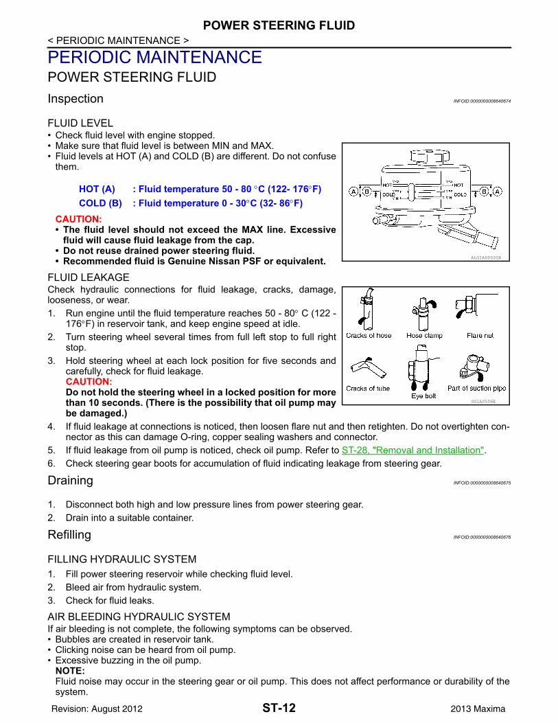
< PERIODIC MAINTENANCE >PERIODIC MAINTENANCEPOWER STEERING FLUIDInspection INFOID:0000000008640674
FLUID LEVEL• Check fluid level with engine stopped.• Make sure that fluid level is between MIN and MAX.• Fluid levels at HOT (A) and COLD (B) are different. Do not confuse
them.
CAUTION:• The fluid level should not exceed the MAX line. Excessive
fluid will cause fluid leakage from the cap.• Do not reuse drained power steering fluid.• Recommended fluid is Genuine Nissan PSF or equivalent.
FLUID LEAKAGECheck hydraulic connections for fluid leakage, cracks, damage,looseness, or wear.1. Run engine until the fluid temperature reaches 50 - 80° C (122 -
176°F) in reservoir tank, and keep engine speed at idle.2. Turn steering wheel several times from full left stop to full right
stop.3. Hold steering wheel at each lock position for five seconds and
carefully, check for fluid leakage.CAUTION:Do not hold the steering wheel in a locked position for morethan 10 seconds. (There is the possibility that oil pump maybe damaged.)
4. If fluid leakage at connections is noticed, then loosen flare nut and then retighten. Do not overtighten con-nector as this can damage O-ring, copper sealing washers and connector.
5. If fluid leakage from oil pump is noticed, check oil pump. Refer to ST-28, "Removal and Installation".6. Check steering gear boots for accumulation of fluid indicating leakage from steering gear.
Draining INFOID:0000000008640675
1. Disconnect both high and low pressure lines from power steering gear.2. Drain into a suitable container.
Refilling INFOID:0000000008640676
FILLING HYDRAULIC SYSTEM1. Fill power steering reservoir while checking fluid level.2. Bleed air from hydraulic system.3. Check for fluid leaks.
AIR BLEEDING HYDRAULIC SYSTEMIf air bleeding is not complete, the following symptoms can be observed.• Bubbles are created in reservoir tank.• Clicking noise can be heard from oil pump.• Excessive buzzing in the oil pump.
NOTE:Fluid noise may occur in the steering gear or oil pump. This does not affect performance or durability of thesystem.
HOT (A) : Fluid temperature 50 - 80 °C (122- 176°F)COLD (B) : Fluid temperature 0 - 30°C (32- 86°F)
ALGIA0002GB
SGIA0506E
ST-12Revision: August 2012 2013 Maxima

POWER STEERING FLUID
C
D
E
F
H
I
J
K
L
M
A
B
T
N
O
P
< PERIODIC MAINTENANCE >
S
1. Turn steering wheel several times from full left stop to full right stop with engine off.CAUTION:Do not allow the fluid level to drop below the MIN line.
2. Start engine and hold steering wheel at each lock position for three seconds at idle to check for fluid leak-age.
3. Repeat step 2 above several times at approximately three second intervals.CAUTION:Do not hold the steering wheel in a locked position for more than 10 seconds. (There is the possi-bility that oil pump may be damaged.)
4. Check fluid for bubbles or white contamination.5. Stop engine if bubbles or white contamination is present. Perform step 2 and 3 above after waiting until
bubbles or white contamination disappear.6. Stop the engine, and then check fluid level.
ST-13Revision: August 2012 2013 Maxima

STEERING WHEEL
< PERIODIC MAINTENANCE >STEERING WHEELInspection INFOID:0000000008640677INSTALLATION CONDITION• Check installation conditions of steering gear assembly, front suspension assembly, axle and steering col-
umn assembly.• Check if movement exists when steering wheel is moved up and down, to the left and right and to the axial
direction.
• Check steering gear assembly bolts and nut for looseness. Refer to ST-26, "Exploded View".
STEERING WHEEL PLAY• Turn steering wheel so that front wheels come to the straight-ahead position. Start engine and lightly turn
steering wheel to the left and right until front wheels start to move. Measure steering wheel movement on theouter circumference.
• When the measurement value is outside the standard value, check backlash for each joint of steering col-umn assembly and installation condition of steering gear assembly.
NEUTRAL POSITION OF STEERING WHEEL• Make sure that steering gear assembly, steering column assembly and steering wheel are installed in the
correct position.• Perform neutral position inspection after wheel alignment. Refer to FSU-6, "Inspection and Adjustment".• Set vehicle to the straight-ahead position and confirm steering wheel is in the neutral position.• Loosen outer socket lock nut and turn inner socket to left and right equally to make fine adjustments if steer-
ing wheel is not in the neutral position.
STEERING WHEEL TURNING FORCE1. Park vehicle on a level, dry surface and set parking brake.2. Start engine.3. Bring power steering fluid up to adequate operating temperature. Make sure the fluid temperature is
approximately 50 - 80°C (122 - 176°F).Tires need to be inflated to normal pressure.
4. Check steering wheel turning force using Tool when steeringwheel has been turned 360 degrees from the neutral position.
5. If steering wheel turning force is out of specification, check rack sliding force.
Steering wheel axial end play : Refer to ST-37, "Steering Wheel"
Steering wheel play : Refer to ST-37, "Steering Wheel"
Tool number : — (J-44372)
Steering wheel turning force
: Refer to ST-37, "Steering Wheel"
WGIA0035E
ST-14Revision: August 2012 2013 Maxima

STEERING WHEEL
C
D
E
F
H
I
J
K
L
M
A
B
T
N
O
P
< PERIODIC MAINTENANCE >
S
a. While pulling outer socket slowly in ±11.5 mm (±0.453 in) rangefrom neutral position, make sure rack sliding force is withinspecification using Tool.
b. If rack sliding force is not within specification, replace steeringgear assembly.
6. If rack sliding force is OK, inspect steering column. Refer to ST-23, "Removal and Installation".
FRONT WHEEL TURNING ANGLE• Check front wheel turning angle after toe-in inspection. Place front
wheels on turning radius gauges and rear wheels on stands.Check the maximum inner and outer wheel turning angles for LHand RH road wheels.
• With the engine at idle, turn steering wheel from full left stop to fullright stop and measure the turning angles.
• Measure rack stroke in neutral position if angles are outside thespecified value.
Tool number : — (J-44372)
Rack sliding force : Refer to ST-38, "Steering Gear"
SST090B
FAA0016D
Inner wheel angle (A) : Refer to ST-37, "Steering Angle"
Outer wheel angle (B) : Refer to ST-37, "Steering Angle"
SGIA0055E
Rack stroke in neutral position (L)
: Refer to ST-38, "Steering Gear"
AWGIA0003GB
ST-15Revision: August 2012 2013 Maxima

POWER STEERING OIL PUMP
< PERIODIC MAINTENANCE >POWER STEERING OIL PUMPInspection INFOID:0000000008640678RELIEF OIL PRESSURECAUTION:Make sure that belt tension is normal before starting the following procedure.1. Connect the Tool between oil pump discharge connector and
high-pressure hose. Bleed air from the hydraulic circuit whileopening the shut-off valve fully. Refer to ST-12, "Inspection".
2. Start engine. Run engine until power steering fluid temperaturereaches 50 - 80°C (122 - 176°F).CAUTION:• Leave the shut-off valve of the Tool fully open while start-
ing and running engine. If engine is started with the shut-off valve closed, the hydraulic pressure in oil pump goesup to the relief pressure along with unusual increase ofpower steering fluid temperature.
• Be sure to keep hose clear of belts and other parts whenengine is started.
3. Fully close the shut-off valve with engine at idle and measurethe relief oil pressure.
CAUTION:Do not keep shut-off valve closed for 10 seconds or longer.
4. Open the shut-off valve slowly after measuring. Replace oil pump if the relief oil pressure is outside thestandard.
5. After inspection, disconnect the Tool from hydraulic circuit, then add power steering fluid and perform airbleeding. Refer to ST-12, "Inspection".
Tool numbers : KV48103500 (J-26357) : KV48102500 (J-33914)
Relief oil pressure : Refer to ST-39, "Oil Pump"
SGIA0915E
ST-16Revision: August 2012 2013 Maxima

STEERING WHEEL
C
D
E
F
H
I
J
K
L
M
A
B
T
N
O
P
< REMOVAL AND INSTALLATION >
S
REMOVAL AND INSTALLATIONSTEERING WHEELRemoval and Installation INFOID:0000000008640679
REMOVALNOTE:When removing spiral cable, use tape so that the case and rotating part keep aligned. This will prevent neutralposition alignment procedure during spiral cable installation.1. Set steering wheel to the straight-ahead position.2. Remove driver air bag module. Refer to SR-4, "Removal and Installation".3. Remove steering wheel lock nut after steering is locked.4. Remove steering wheel using Tool (A).
INSTALLATIONInstallation is in the reverse order of removal.CAUTION:Do not rotate spiral cable freely or excessively when the steering wheel is removed. Doing so maycause spiral cable damage.NOTE:• Check the spiral cable neutral position after replacing or rotating spiral cable. Refer to SR-7, "Removal and
Installation".• Tighten the steering wheel lock nut to specification. Refer to ST-22, "Exploded View".
Tool number (A) : ST27180001 (J-25726-A)
JSGIA0341ZZ
ST-17Revision: August 2012 2013 Maxima

TILT MOTOR
< REMOVAL AND INSTALLATION >TILT MOTORExploded View INFOID:0000000008640680Removal and Installation INFOID:0000000008640681
REMOVAL1. Remove instrument lower panel LH. Refer to IP-10, "Exploded View".2. Remove lower knee protector LH bolts (A) and the lower knee
protector LH (B).
3. Telescope the steering wheel to the full out position and tilt to highest position.NOTE:If either function is inoperative you can do this manually prior to installation.
4. Remove the steering column covers. Refer to IP-11, "Removal and Installation".NOTE:
1. Steering column assembly 2. Telescope motor 3. Telescope motor link bracket4. Tilt motor 5. Tilt motor bolt cap
ALGIA0054GB
ALGIA0050ZZ
ST-18Revision: August 2012 2013 Maxima

TILT MOTOR
C
D
E
F
H
I
J
K
L
M
A
B
T
N
O
P
< REMOVAL AND INSTALLATION >
S
The tilt/telescope switch can remain attached to the side cover.5. Remove the tilt motor as follows.
1. Disconnect the tilt motor harness connector (A). 2. Remove the tilt motor link bolts (B).
3. Remove the tilt motor bolt (A) from the RH side of column.4. Remove the tilt motor (B).NOTE:If the steering wheel could not be tilted to the highest position,manually tilt steering wheel to the highest position.
INSTALLATIONInstallation is in the reverse order of removal.NOTE:• When installing the tilt motor link bolts, manually move steering wheel up and down to align the bolt holes.• Inform customer that they will need to reset their Automatic Drive Positioner (ADP) settings.
ALGIA0051ZZ
ALGIA0052ZZ
ST-19Revision: August 2012 2013 Maxima

TELESCOPIC MOTOR
< REMOVAL AND INSTALLATION >TELESCOPIC MOTORExploded View INFOID:0000000008640682Removal and Installation INFOID:0000000008640683
REMOVAL1. Remove instrument lower panel LH. Refer to IP-10, "Exploded View".2. Remove lower knee protector LH bolts (A) and the lower knee
protector LH (B).
3. Telescope the steering wheel to the full out position and tilt to highest position.NOTE:If either function is inoperative you can do this manually prior to installation.
4. Remove the steering column covers. Refer to IP-11, "Removal and Installation".NOTE:
1. Steering column assembly 2. Telescope motor 3. Telescope motor link bracket4. Tilt motor 5. Tilt motor bolt cap
ALGIA0054GB
ALGIA0050ZZ
ST-20Revision: August 2012 2013 Maxima

TELESCOPIC MOTOR
C
D
E
F
H
I
J
K
L
M
A
B
T
N
O
P
< REMOVAL AND INSTALLATION >
S
The tilt/telescope switch can remain attached to the side cover.5. Remove telescope motor as follows.
1. Disconnect telescope motor harness connector (A).2. Remove the two telescope motor link screws (B) and tele-
scope motor link bracket.3. Remove telescope motor bolt (C).4. Remove the telescope motor (D).
NOTE:If the steering wheel could not be telescoped to full out posi-tion manually pull steering wheel to the full out position.
INSTALLATIONInstallation is in the reverse order of removal.NOTE:• Adjust the telescope motor link to full out position and adjust as needed to fit into proper installed position.• Inform customer that they will need to reset their Automatic Drive Positioner (ADP) settings.
ALGIA0053ZZ
ST-21Revision: August 2012 2013 Maxima

STEERING COLUMN
< REMOVAL AND INSTALLATION >STEERING COLUMNExploded View INFOID:0000000008640684Without Electric Motor
AWGIA0105GB
1-4. Steering column assembly nut tight-ening order
5. Steering wheel 6. Combination switch and spiral cable
7. Steering column assembly 8. Hole cover seal 9. Herbie clip10. Hole cover 11. Lower shaft assembly
ST-22Revision: August 2012 2013 Maxima

STEERING COLUMN
C
D
E
F
H
I
J
K
L
M
A
B
T
N
O
P
< REMOVAL AND INSTALLATION >
S
With Electric Motor
Removal and Installation INFOID:0000000008640685
REMOVALHole Cover Seal, Hole Cover and Lower Shaft Assembly1. Set wheels to the straight-ahead position.2. Remove lower side bolt (A) of lower shaft assembly (1).
• Steering gear (2)
3. Remove the instrument lower panel LH. Refer to IP-19, "Removal and Installation".
AWGIA0098GB
1-4. Steering column assembly nut tight-ening order
5. Steering wheel 6. Combination switch and spiral cable
7. Steering column assembly 8. Hole cover seal 9. Herbie clip10. Hole cover 11. Lower shaft assembly
ALGIA0041ZZ
ST-23Revision: August 2012 2013 Maxima

STEERING COLUMN
< REMOVAL AND INSTALLATION >4. Remove bolt (A) and nut (B) of column upper joint (2), thenremove lower shaft assembly (1).CAUTION:Do not reuse column upper joint nut.
5. Loosen herbie clip, then remove hole cover seal from holecover.
6. Remove nuts of hole cover, and then remove clamp and holecover from dash panel.
Steering Column Assembly1. Set wheels to the straight-ahead position.2. Remove instrument side finisher LH. Refer to IP-10, "Exploded View".3. Remove instrument lower panel LH. Refer to IP-10, "Exploded View".4. Remove lower knee protector LH bolts ( )(, then remove lower
knee protector LH (1). Refer to IP-10, "Exploded View".5. Remove steering column upper and lower covers. Refer to IP-
10, "Exploded View".6. Remove combination switch and spiral cable. Refer to SR-7,
"Removal and Installation".7. Disconnect each switch harness connector installed to steering
column assembly, and then disconnect harness clips from steer-ing column assembly.
8. Remove bolt (A) and nut (B) of column upper joint (2).• Lower shaft assembly (1)CAUTION:Do not reuse column upper joint nut.
9. Remove steering column assembly nuts, then remove steeringcolumn assembly.
INSPECTION AFTER REMOVALHole Cover Seal, Hole Cover and Lower Shaft AssemblyCheck each part of hole cover seal, hole cover and steering column and lower shaft assembly for damage orother malfunctions. Replace if necessary.Steering Column Assembly• Check each part of steering column assembly for damage or other malfunctions. Replace entire steering col-
umn assembly if any parts are damaged.
ALGIA0042ZZ
ALGIA0043ZZ
ALGIA0042ZZ
ST-24Revision: August 2012 2013 Maxima
STEERING COLUMN
C
D
E
F
H
I
J
K
L
M
A
B
T
N
O
P
< REMOVAL AND INSTALLATION >
S
• Measure the length (L) as shown if vehicle has been involved in aminor collision. Replace steering column assembly if outside thespecifications.
• Measure steering column rotating torque using Tool. Replace steering column assembly if outside the stan-dard.
• Check tilt and telescopic mechanism operating range (L1), (L2) asshown.
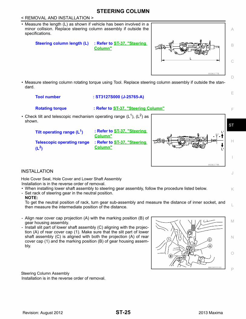
INSTALLATIONHole Cover Seal, Hole Cover and Lower Shaft Assembly Installation is in the reverse order of removal. • When installing lower shaft assembly to steering gear assembly, follow the procedure listed below.- Set rack of steering gear in the neutral position.
NOTE:To get the neutral position of rack, turn gear sub-assembly and measure the distance of inner socket, andthen measure the intermediate position of the distance.
- Align rear cover cap projection (A) with the marking position (B) ofgear housing assembly.
- Install slit part of lower shaft assembly (C) aligning with the projec-tion (A) of rear cover cap (1). Make sure that the slit part of lowershaft assembly (C) is aligned with both the projection (A) of rearcover cap (1) and the marking position (B) of gear housing assem-bly.
Steering Column AssemblyInstallation is in the reverse order of removal.
Steering column length (L) : Refer to ST-37, "Steering Column"
SGIA1177E
Tool number : ST3127S000 (J-25765-A)
Rotating torque : Refer to ST-37, "Steering Column"
Tilt operating range (L1) : Refer to ST-37, "Steering Column"
Telescopic operating range (L2)
: Refer to ST-37, "Steering Column"
SGIA1179E
AWGIA0221ZZ
ST-25Revision: August 2012 2013 Maxima

STEERING GEAR AND LINKAGE
< REMOVAL AND INSTALLATION >STEERING GEAR AND LINKAGEExploded View INFOID:0000000008640686Removal and Installation INFOID:0000000008640687
NOTE:When removing components such as hoses, tubes/lines, etc., cap or plug openings to prevent fluid from spill-ing.
REMOVAL1. Remove front wheels and tires using power tool. Refer to WT-60, "Adjustment".2. Drain power steering fluid. Refer to ST-12, "Draining".3. Disconnect front stabilizer connecting rods from front stabilizer and reposition front stabilizer. Refer to
FSU-11, "Removal and Installation".4. Remove steering outer socket cotter pins (1), and then loosen
the nuts.5. Remove steering outer sockets (2) from steering knuckles (3) so
as not to damage ball joint boots (4) using Tool.CAUTION:Temporarily tighten the nut to prevent damage to threadsand to prevent the Tool from suddenly coming off.
1. Cotter pin 2. Steering gear assembly Front
AWGIA0149GB
Tool number : HT72520000 (J-25730-A)
SGIA1183E
ST-26Revision: August 2012 2013 Maxima
STEERING GEAR AND LINKAGE
C
D
E
F
H
I
J
K
L
M
A
B
T
N
O
P
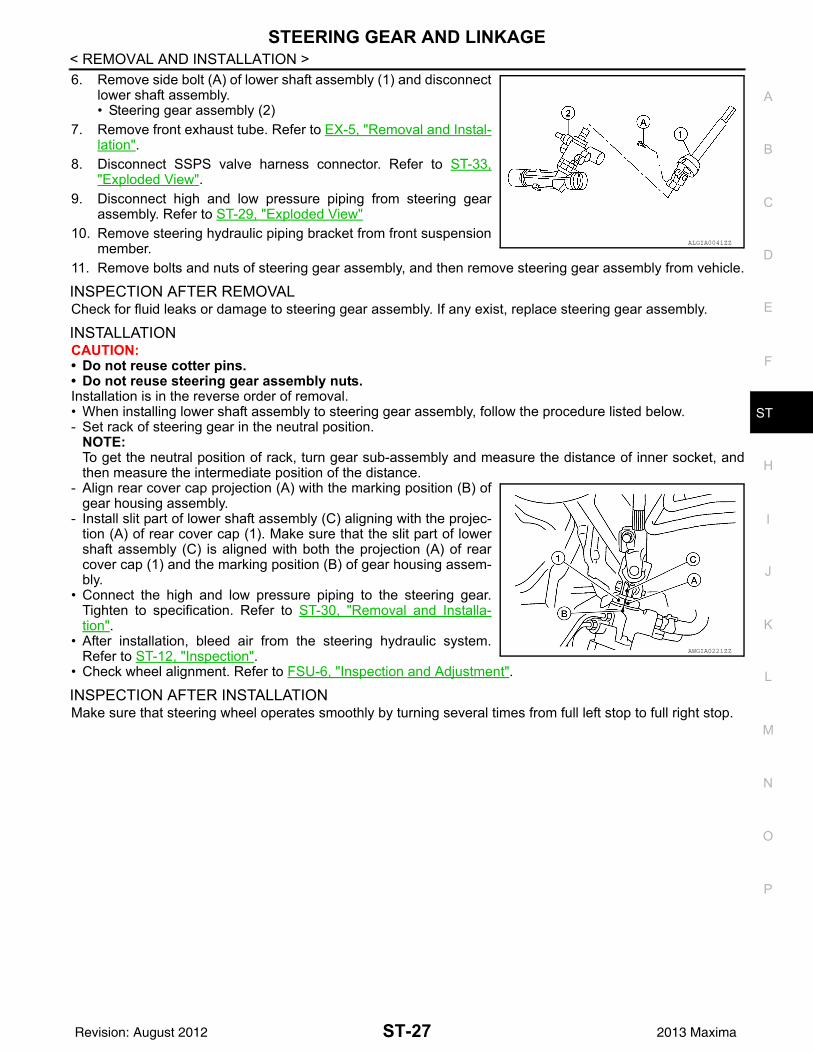
< REMOVAL AND INSTALLATION >
S
6. Remove side bolt (A) of lower shaft assembly (1) and disconnectlower shaft assembly.• Steering gear assembly (2)
7. Remove front exhaust tube. Refer to EX-5, "Removal and Instal-lation".
8. Disconnect SSPS valve harness connector. Refer to ST-33,"Exploded View".
9. Disconnect high and low pressure piping from steering gearassembly. Refer to ST-29, "Exploded View"
10. Remove steering hydraulic piping bracket from front suspensionmember.
11. Remove bolts and nuts of steering gear assembly, and then remove steering gear assembly from vehicle.
INSPECTION AFTER REMOVALCheck for fluid leaks or damage to steering gear assembly. If any exist, replace steering gear assembly.
INSTALLATIONCAUTION:• Do not reuse cotter pins.• Do not reuse steering gear assembly nuts.Installation is in the reverse order of removal. • When installing lower shaft assembly to steering gear assembly, follow the procedure listed below.- Set rack of steering gear in the neutral position.
NOTE:To get the neutral position of rack, turn gear sub-assembly and measure the distance of inner socket, andthen measure the intermediate position of the distance.
- Align rear cover cap projection (A) with the marking position (B) ofgear housing assembly.
- Install slit part of lower shaft assembly (C) aligning with the projec-tion (A) of rear cover cap (1). Make sure that the slit part of lowershaft assembly (C) is aligned with both the projection (A) of rearcover cap (1) and the marking position (B) of gear housing assem-bly.
• Connect the high and low pressure piping to the steering gear.Tighten to specification. Refer to ST-30, "Removal and Installa-tion".
• After installation, bleed air from the steering hydraulic system.Refer to ST-12, "Inspection".
• Check wheel alignment. Refer to FSU-6, "Inspection and Adjustment".
INSPECTION AFTER INSTALLATIONMake sure that steering wheel operates smoothly by turning several times from full left stop to full right stop.
ALGIA0041ZZ
AWGIA0221ZZ
ST-27Revision: August 2012 2013 Maxima

POWER STEERING OIL PUMP
< REMOVAL AND INSTALLATION >POWER STEERING OIL PUMPExploded View INFOID:0000000008640688Removal and Installation INFOID:0000000008640689
NOTE:When removing components such as hoses, tubes/lines, etc., cap or plug openings to prevent fluid from spill-ing.
REMOVAL1. Remove front wheel and tire (RH) using power tool. Refer to WT-60, "Adjustment".2. Remove front fender protector side cover. Refer to EXT-23, "Exploded View".3. Remove hood ledge cover (RH).4. Drain power steering fluid. Refer to ST-12, "Draining".5. Disconnect the power steering pressure sensor harness connector at the high pressure pipe. Refer to ST-
29, "Exploded View".6. Disconnect high pressure piping and suction hose from power steering oil pump. Refer to ST-29,
"Exploded View".7. Loosen drive belt. Refer to EM-14, "Removal and Installation".8. Remove drive belt from power steering oil pump pulley.9. Remove power steering oil pump bolts, and then remove power steering oil pump.
INSTALLATIONInstallation is in the reverse order of removal.• When installing power steering oil pump, install all bolts by hand initially, then tighten bolts to specification.• Perform the following procedures after installing.- Check belt tension. Refer to EM-14, "Checking Drive Belts".- Bleed air from power steering system. Refer to ST-12, "Refilling".
1. Rear bracket 2. Power steering oil pump assembly 3. Front bracket
AWGIA0099GB
ST-28Revision: August 2012 2013 Maxima
HYDRAULIC LINE
C
D
E
F
H
I
J
K
L
M
A
B
T
N
O
P
< REMOVAL AND INSTALLATION >
S
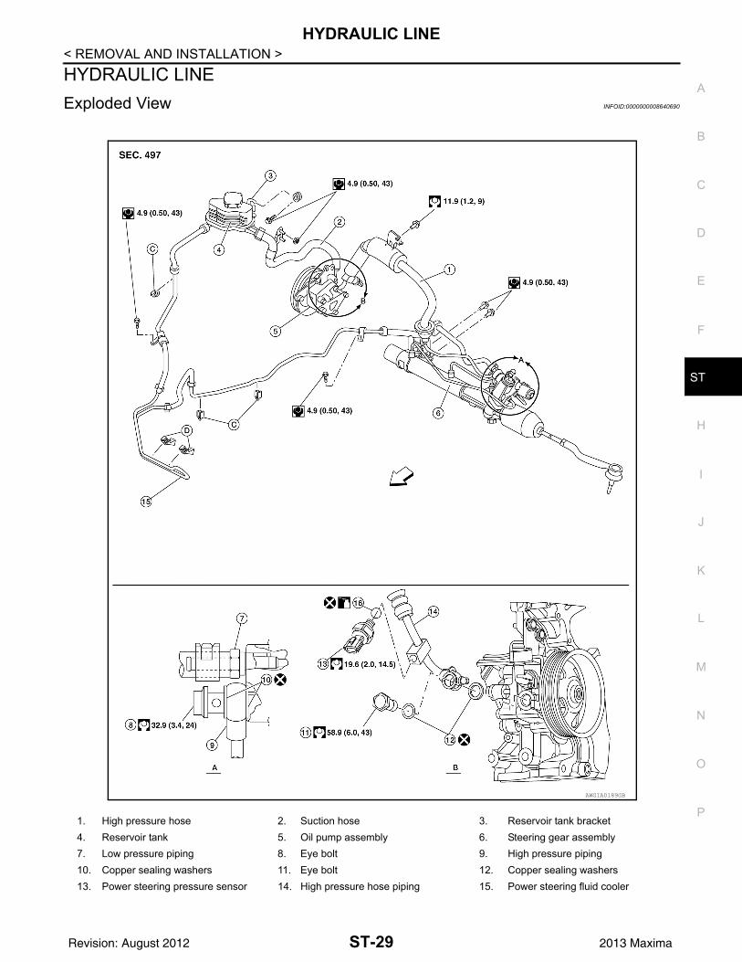
HYDRAULIC LINEExploded View INFOID:0000000008640690
1. High pressure hose 2. Suction hose 3. Reservoir tank bracket4. Reservoir tank 5. Oil pump assembly 6. Steering gear assembly7. Low pressure piping 8. Eye bolt 9. High pressure piping10. Copper sealing washers 11. Eye bolt 12. Copper sealing washers13. Power steering pressure sensor 14. High pressure hose piping 15. Power steering fluid cooler
AWGIA0189GB
ST-29Revision: August 2012 2013 Maxima

HYDRAULIC LINE
< REMOVAL AND INSTALLATION >Removal and Installation INFOID:0000000008640691
CAUTION:• Securely insert harness connector to pressure sensor.• Do not reuse O-rings or copper sealing washers.NOTE:When removing components such as hoses, tubes/lines, etc., cap or plug openings to prevent fluid from spill-ing.
REMOVALRefer to ST-29, "Exploded View" for removal.
INSTALLATION• Insert hose securely until it contacts tube spool.
CAUTION:Do not use lubricant on hose or fitting.
• Install eye-bolt (1), copper sealing washers (2) and eye-joint(assembled to high-pressure hose) (4) onto oil pump assembly (3),and temporarily tighten the eye-bolt, then tighten it to the specifiedtorque.CAUTION:Do not reuse copper sealing washers.
16. O-ring Front A. View A
B. View B
SGIA0514E
AWGIA0106ZZ
ST-30Revision: August 2012 2013 Maxima
STEERING COLUMN
C
D
E
F
H
I
J
K
L
M
A
B
T
N
O
P
< UNIT DISASSEMBLY AND ASSEMBLY >
S
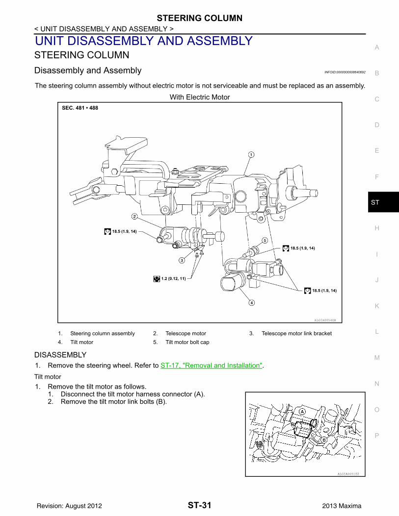
UNIT DISASSEMBLY AND ASSEMBLYSTEERING COLUMNDisassembly and Assembly INFOID:0000000008640692
The steering column assembly without electric motor is not serviceable and must be replaced as an assembly.
With Electric Motor
DISASSEMBLY1. Remove the steering wheel. Refer to ST-17, "Removal and Installation".Tilt motor1. Remove the tilt motor as follows.
1. Disconnect the tilt motor harness connector (A). 2. Remove the tilt motor link bolts (B).
ALGIA0054GB
1. Steering column assembly 2. Telescope motor 3. Telescope motor link bracket4. Tilt motor 5. Tilt motor bolt cap
ALGIA0051ZZ
ST-31Revision: August 2012 2013 Maxima

STEERING COLUMN
< UNIT DISASSEMBLY AND ASSEMBLY >3. Remove the tilt motor bolt (A) from the RH side of column.4. Remove the tilt motor (B).NOTE:If the steering wheel could not be tilted to the highest position,manually tilt steering wheel to the highest position.
Telescope motor1. Remove telescope motor as follows.
1. Disconnect telescope motor harness connector (A).2. Remove the two telescope motor link screws (B) and tele-
scope motor link bracket.3. Remove telescope motor bolt (C).4. Remove the telescope motor (D).
NOTE:If the steering wheel could not be telescoped to full out posi-tion manually pull steering wheel to the full out position
ASSEMBLYAssembly is in the reverse order of removalNOTE:• Upon installation of the tilt motor link bolts manually move steering wheel up and down to align the bolts.• Adjust the telescope motor link to full out position and adjust as needed to fit into proper installed position.• Inform customer that they will need to reset their Automatic Drive Positioner (ADP) settings.
ALGIA0052ZZ
ALGIA0053ZZ
ST-32Revision: August 2012 2013 Maxima

STEERING GEAR AND LINKAGE
C
D
E
F
H
I
J
K
L
M
A
B
T
N
O
P
< UNIT DISASSEMBLY AND ASSEMBLY >
S
STEERING GEAR AND LINKAGEExploded View INFOID:0000000008640693
Disassembly INFOID:0000000008640694
1. Remove outer socket locknut and outer socket.2. Remove boot clamps and boot.
CAUTION:Do not reuse boot clamps.
3. Remove inner socket.
Inspection INFOID:0000000008640695
INSPECTION AFTER DISASSEMBLYBootCheck boot for cracks. Replace if any damage is found.Outer Socket and Inner Socket• Ball joint swinging torque
1. Outer socket 2. Boot clamp 3. Boot4. Inner socket 5. Boot clamp 6. SSPS valve (part of gear assembly)7. Gear assembly Front Three Bond 1111B or equivalent
AWGIA0101GB
ST-33Revision: August 2012 2013 Maxima

STEERING GEAR AND LINKAGE
< UNIT DISASSEMBLY AND ASSEMBLY >- Hook a spring balance to the ball stud and inner socket measuringpoint (*) and pull the spring balance. Make sure that the spring bal-ance reads the specified value when ball stud and inner socketstart to move. Replace outer socket and steering gear assembly ifthey are outside the standard.
• Ball joint rotating torque- Make sure that the reading is within the following specified range
using Tool. Replace outer socket if the reading is outside the spec-ified value.
• Ball joint axial end play- Apply an axial load of 490 N (50 kg, 111 lb) to ball stud. Measure
amount of stud movement using a dial gauge and then make surethat the value is within the following specified range. Replace outersocket and inner socket if the measured value is outside the stan-dard.
Assembly INFOID:0000000008640696
1. Apply Three Bond 1111B or equivalent to inner socket and turn pinion fully to retract inner socket into gearhousing assembly.
2. Install large end (1) of boot (2) to gear housing assembly.3. Install small end (3) of boot (2) to inner socket boot mounting
groove.
Tool number : — (J-44372)
Swinging torque : Refer to ST-38, "Steering Gear"
SGIA0896E
Tool number : ST3127S000 (J-25765-A)
Rotating torque : Refer to ST-38, "Steering Gear"
SGIA0941E
Axial end play : Refer to ST-38, "Steering Gear"
SGIA0057E
AWGIA0107ZZ
ST-34Revision: August 2012 2013 Maxima

STEERING GEAR AND LINKAGE
C
D
E
F
H
I
J
K
L
M
A
B
T
N
O
P
< UNIT DISASSEMBLY AND ASSEMBLY >
S
4. Install boot clamp to boot small end.CAUTION:Do not reuse boot clamps.
5. Install boot clamp to boot large end using Tool.CAUTION:Do not reuse boot clamps.
6. Adjust inner socket to standard length (L), and then tighten locknut to the specified torque. Check length of inner socket (L)again after tightening lock nut. Make sure that the length is thestandard.
CAUTION:Adjust toe-in after this procedure. The length achieved aftertoe-in adjustment is not necessarily the above value.
Tool number : KV40107300 ( — )
AST139
Inner socket length (L) : Refer to ST-38, "Steering Gear"
SGIA0167E
ST-35Revision: August 2012 2013 Maxima

POWER STEERING OIL PUMP
< UNIT DISASSEMBLY AND ASSEMBLY >POWER STEERING OIL PUMPDisassembly and Assembly INFOID:0000000008640697The power steering oil pump and pulley is not serviceable and should be replaced as an assembly. For frontand rear bracket removal, refer to ST-28, "Exploded View".
ST-36Revision: August 2012 2013 Maxima

SERVICE DATA AND SPECIFICATIONS (SDS)
C
D
E
F
H
I
J
K
L
M
A
B
T
N
O
P
< SERVICE DATA AND SPECIFICATIONS (SDS)
S
SERVICE DATA AND SPECIFICATIONS (SDS)SERVICE DATA AND SPECIFICATIONS (SDS)Steering Wheel INFOID:0000000008640698
Steering Angle INFOID:0000000008640699
Unit: Degree minute (Decimal Degree)
Steering Column INFOID:0000000008640700
STEERING COLUMN LENGTHUnit: mm (in)
STEERING COLUMN ROTATING TORQUE Unit: N·m (kg-m, in-lb)
TILT MECHANISM OPERATING RANGE
Steering wheel axial end play 0 mm (0 in)
Steering wheel play 0 - 35 mm (0 - 1.38 in)
Steering wheel turning force 39 N (4 kg-f, 9 lb-f) or less
Tire size P245/45R18 P245/40R19
Inner wheel angle (A)
Minimum 33° 30′ (33.5°) 33° 30′ (33.5°)
Nominal 36° 30′ (36.5°) 36° 30′ (36.5°)
Maximum 37° 30′ (37.5°) 37° 30′ (37.5°)
Outer wheel angle (B) Nominal 31° 0′ (31.0°) 31° 0′ (31.0°)
SGIA0055E
Steering column length (L)Telescopic maximum 513 - 543 (20.20 - 21.38)
Telescopic minimum 503 - 513 (19.80 - 20.20)
SGIA1177E
Rotating torque 0 - 0.25 (0 - 0.03, 0 - 2)
ST-37Revision: August 2012 2013 Maxima
SERVICE DATA AND SPECIFICATIONS (SDS)
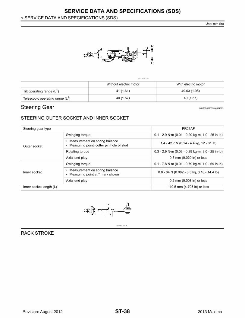
< SERVICE DATA AND SPECIFICATIONS (SDS)Unit: mm (in)
Steering Gear INFOID:0000000008640701
STEERING OUTER SOCKET AND INNER SOCKET
RACK STROKE
Without electric motor With electric motor
Tilt operating range (L1) 41 (1.61) 49.63 (1.95)
Telescopic operating range (L2) 40 (1.57) 40 (1.57)
SGIA1179E
Steering gear type PR26AF
Outer socket
Swinging torque 0.1 - 2.9 N·m (0.01 - 0.29 kg-m, 1.0 - 25 in-lb)
• Measurement on spring balance• Measuring point: cotter pin hole of stud 1.4 - 42.7 N (0.14 - 4.4 kg, 12 - 31 lb)
Rotating torque 0.3 - 2.9 N·m (0.03 - 0.29 kg-m, 3.0 - 25 in-lb)
Axial end play 0.5 mm (0.020 in) or less
Inner socket
Swinging torque 0.1 - 7.8 N·m (0.01 - 0.79 kg-m, 1.0 - 69 in-lb)
• Measurement on spring balance• Measuring point at * mark shown 0.8 - 64 N (0.082 - 6.5 kg, 0.18 - 14.4 lb)
Axial end play 0.2 mm (0.008 in) or less
Inner socket length (L) 119.5 mm (4.705 in) or less
SGIA0950E
ST-38Revision: August 2012 2013 Maxima

SERVICE DATA AND SPECIFICATIONS (SDS)
C
D
E
F
H
I
J
K
L
M
A
B
T
N
O
P
< SERVICE DATA AND SPECIFICATIONS (SDS)
S
RACK SLIDING FORCE
Oil Pump INFOID:0000000008640702
Steering Fluid INFOID:0000000008640703
Steering gear model PR26AF
Tire size P245/45R18 P245/40R19
Rack stroke in neutral position (L) 69.5 ±0.75 mm (2.735 ± 0.030 in)
AWGIA0003GB
Standard 301 ± 49 N (30.7 ± 5 kg-f, 67.7 ± 11 lb-f)
Minimum 210 N (21.4 kg-f, 47.2 lb-f)
Relief oil pressure at 1,000 rpm 9,800 + 500/ - 300 kPa (99.96 + 5.10/ - 3.06 kg/cm2, 1,421.0 + 72.5/ - 43.5 psi)
Fluid type and capacity Refer to MA-16, "FOR USA AND CANADA : Fluids and Lubricants" (United States and Canada), MA-17, "FOR MEXICO : Fluids and Lubricants" (Mexico).
ST-39Revision: August 2012 2013 Maxima