Embed Size (px)
Citation preview

Steel Structural Design Bolted & Welded
Connections
Team TeachingStructural Design FTUI 2011

Introduction
Connections of structural steel members are of critical importance. An inadequate connection, which can be the
“weak link” in a structure, has been the cause of numerous failures.
Failure of structural members is rare; most structural failures are the result of poorly designed or detailed
connections.
Modern steel structures are connected by welding or bolting (either high-strength or “common” bolts) or by
combination of both.
Welding has several advantages over bolting. A welded connection is often simpler in concept and requires few,
if any, holes. Connection that are extremely complex with fasteners can become very simple when welds are
used.

Example plate girder:
Riveted Welded

Steel Connections

Combination weld and bolts:
• Welding can be done in the shop and bolting in the field.• Example : in the single-plate beam-to-column connection below, the plate is shop welded to the column flange and field bolted to the beam web.
h

Tension member connection and splice. It subjects the bolts to forces that tend to shear the shank.
Beam end simple connection. It subjects the bolts to forces that tend to shear the shank.
Hanger connection. The hanger connection puts the bolts in tension
Types of Bolted connections based on loading types

The bolts are subjected to shear or tension loading. In most bolted connection, the bolts are subjected
to shear. Bolts can fail in shear or in tension.
Simple connection: If the line of action of the force acting on the connection passes through the center of gravity of the connection, then each bolt can be assumed to resist an equal share of the load.
The strength of the simple connection will be equal to the sum of the strengths of the individual bolts in the connection.
Simple Bolted Connections

Design Concept : f Rn > Pu
where : f Rn = Factored design strength
Pu = factored load.
We need to examine the various possible failure modes and calculate the corresponding design strengths ( f Rn )
Possible failure modes are:1. Shear failure of the bolts2. Failure of connected member (failure mode of tension member) 3. Edge tearing or fracture of the connected plate (gusset plate)4. Excessive bearing deformation at the bolt hole (bearing
failure of bolts)
Bolted Shear Connections

Shearing stress in the bolt : fv = P/A = P/(p db2/4)
Strength of the bolt : P = fv x (p db2/4)
Where : P = load acting on an individual bolt A = area of the bolt and db is its diameter
fv = shear yield stress = 0.6Fy
Bolts can be in single shear or double shear as shown below.
When the bolt is in double shear, two cross-sections are effective in resisting the load. The bolt in double shear will have the twice the shear strength of a bolt in single shear.
Shear failure of bolts

Single & double shear
When the bolt is in double shear, two cross-sections are effective in resisting the load. The bolt in double shear will have the twice the shear strength of a bolt in single shear.

Common Bolts:
Common bolts, also known as unfinished bolts, are designated as ASTM A307,which differ from high-strength bolts not only in material properties, but alsoin that we do not account for the clamping force from the tightening of the bolt.
The nominal shear strength:
bvn AFR .
WhereFv = ultimate shearing stressAb = cross-sectional area of the unthreaded part of the bolt
The design strength: ).(75.0 bvn AFR
For ASTM A307, Fv=24 ksi

High-Strength Bolts
Two type of grades:1. A325 Fy=81- 92 ksi or Fy= 566- 643 MPa measured at 0.2%
offset.2. A490 Fy= 115 - 130 ksi Fy = 803- 908 MPa measured at 0.2%
offset.In certain cases, A325 and A490 bolts are installed to such degree of tightnessthat the are subjected to extremely large tensile force. The purpose of such a large tensile force is to achieve the clamping force.
The total compressive force acting on the connected part is numerically equalto the tension in the bolt. A list of minimum tension values, for those connectionin which a minimum tension is required, is given in AISC Table J3.1.
If an external load P is applied, a friction force will develop between theconnected parts. The maximum possible value of this force is
NF .

Where : m = coefficient of static friction between connected parts, N = the normal compressive force acting on the inner surfaces.
: depend on the surface condition of the steel: Painted or Rusted
(a) For Class A surface (unpainted clean mill scale steel surface orsurface with Class A coating on blast-cleaned steel), = 0.33
(b) For Class B (unpainted blast-cleaned steel surface or surfacewith Class B coating on blast-cleaned steel), = 0.50
(c) For Class C surface (hot-dip galvanized and roughened surface), = 0.40
Thus, each bolt in the connection is capable of resisting a load of P=F, even if the bolt shank does not bear on the connected part. As long as this frictional force does not exceeded, there is no bearing or shear. If P is greater than F and slippage occurs, shear and bearing will then exist and will affect the capacity of the connection.
=mean slip coefficient

Shear Strength of HTB
Fastener Nominal Shear Strength Rn = FvAb
A325N, threads in plane of shear A325X, threads not in plane of shear A490N, threads in plane of shear A490X, threads not in plane of shear
48Ab
60Ab
60Ab
75Ab
The design shear strength of HTB is: ).( bvn AFR where = 0.75
• The nominal shear strength of HTB is given by ultimate shearing stress times the nominal bolt area.
• The shear strength of HTB depends on whether the threads are in plane of shear rather than use a reduced cross-sectional area.
• Approximately, the threaded area = 0.75 x unthreaded area.

Hole is slightly larger than the fastener and the fastener is loosely placed in hole
The stress will be highest at the radial contact point (A).
The average stress can be calculated as : the applied force divided by the projected area of contact
fp = P/(db t)
where P = force applied to the
fastener.
Bearing failure of connected/connecting part due to bearing from bolt holes

The bearing stress state can be complicated at the nearby/edge bolt.
The bolt spacing and edge distance will have an effect on the bearing stress.
Bearing stress effects are independent of the bolt type because the bearing stress acts on the connected plate not the bolt.
A possible failure mode resulting from excessive bearing close to the edge of the connected element is shear tear-out. It can also occur between two holes in the direction of the bearing load.
Bearing Strength
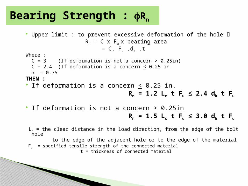
Upper limit : to prevent excessive deformation of the hole Rn = C x Fu x bearing area = C. Fu .db .tWhere : C = 3 (If deformation is not a concern > 0.25in) C = 2.4 (If deformation is a concern < 0.25 in. f = 0.75THEN : If deformation is a concern < 0.25 in. Rn = 1.2 Lc t Fu ≤ 2.4 db t Fu
If deformation is not a concern > 0.25in Rn = 1.5 Lc t Fu ≤ 3.0 db t Fu
Lc = the clear distance in the load direction, from the edge of the bolt hole to the edge of the adjacent hole or to the edge of the material Fu = specified tensile strength of the connected material t = thickness of connected material
Bearing Strength : fRn
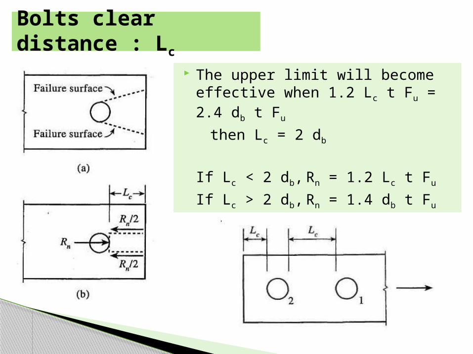
The upper limit will become effective when 1.2 Lc t Fu = 2.4 db t Fu
then Lc = 2 db
If Lc < 2 db, Rn = 1.2 Lc t Fu
If Lc > 2 db, Rn = 1.4 db t Fu
Bolts clear distance : Lc

In a simple connection, all bolts share the load equally.
The shear strength of all bolts = shear strength of one bolt x number of bolts
The bolts are subjected to shear and the connecting / connected plates are subjected to bearing stresses.
The bearing resistance shall be taken as the sum of the bearing resistances of the individual bolts.
Bolted Shear Connections
TT
T/n T/n
T/n T/n
T/n T/n
TT
T/n T/n
T/n T/n
T/n T/n
Bolt in shear
Bearing stresses in plate
Bearing stresses in plate
TT
T
T
Bolt in shear
Bearing stresses in plate
Bearing stresses in plate
Bolt in shear
Bearing stresses in plate
Bearing stresses in plate
TT
T
T

AISC Specifications
AISC Specification
The minimum spacing (s) between the
centers of bolt holes
2 2/3 db or 3db is preferred
The maximum spacing for bolt holes
is
24 times the thickness of the thinner
part (but not more than 12 in.).
The minimum edge distance (Le) from
the center of the bolt to the edge of the
connected part
See AISC Table J3.4
The maximum edge distance (Le) for
bolt holes
12 times the thickness of the
connected part (but not more than 6
in.).

Le
Le s s
(a) (b)
whered= bolt diametert= thickness of connected partFu= tensile strength of connected
parts = spacing of bolts in the direction of
load Le= edge distance in the direction of
load

Table J3.3 Nominal Hole Dimensions
Bolt Diameter
Hole Dimensions
Standard(Dia.)
Oversize(Dia.)
Short-slot(Width x Length)
Long-slot(Width x Length)
½5/8¾
7/81
1 1/8
9/1611/1613/1615/161 1/16d+1/16
5/813/1615/161 1/16
1 ¼d+5/16
9/16 x 11/1611/16 x 7/813/16 x 1
15/16 x 1 1/81 1/16 x 1 5/16
(d+1/16)x(d+3/8)
9/16 x 1 ¼11/16 x 1 9/1613/16 x 1 7/8
15/16 x 2 3/161 1/16 x 2 ½
(d+1/16)x(2.5xd)

Table J3.4 Minimum Edge Distance , [a] in.(Center of Standard Hole[b] to Edge of Connected Part)
Nominal Rivet or Bolt Diameter (in) At Sheared Edges
At Rolled of Plates, Shapes or Bars, or Gas Cut Edges [c]
½5/8¾
7/81
1 1/81 1/4
Over 1 1/4
7/81 1/81 1/4
1 1/2 [d]1 3/4 [d]
22 1/4
1 3/4 x Diameter
¾7/81
1 1/81 1/41 1/21 5/8
1 1/4 x Diameter
[a] Lesser edge distance are permitted to be used provided Equation from J3.10, as appropriate, are satisfied.[b] For oversized or slotted holes, see Table J3.8.[c] All edge distance in this column are permitted to be reduced 1/8-in. when the holes at a point where stress does not exceed 25 percent of the maximum design strength in the element.[d] These are permitted to be 11/4-in. at the ends of beam connection angles and shear end plates.

I. The design shear strength of bolt in shear : f Rn= f Fn Ab = 0.75 x 48 x p x 0.752/4 = 15.9 kips per bolt
Shear strength of connection = 4 x 15.9 = 63.6 kips
II. Check bolts spacing : minimum edge distance = 1 in. for rolled edges of plates (see Table
J.3.4) edge distances (1.25 in.) > 1 in OK min.spacing = 2.67 db = 2.67 x 0.75 = 2.0 in.
preferred spacing = 3.0 db = 3.0 x 0.75 = 2.25 in.
given spacing (2.5 in.) > 2.25 in. OK
Ex. Calculate and check the design strength of the connection. Is the connection adequate for carrying the factored load of 60k.
1.25 2.50 1.25
1.25
2.50
1.2565 k
A36
A36 5 x _
3/8 in.
_ in. bolts
1.25 2.50 1.25
1.25
2.50
1.2565 k
A36
A36 5 x _
3/8 in.
_ in. bolts
1/2
3/4
60 k
A325N

III. Bearing strength at bolt holes (plate 1/2in thickness) edges : Lc = 1.25 – dh/2 = 1.25 – (13/16)/2 = 0.844 in.
fRn = 0.75 (1.2 Lc t Fu) = 0.75(1.2 x 0.844 x 0.5 x 58) = 22.02 kips
upper limit : 0.75 (2.4 db t Fu) = 0.75(2.4 x 0.75 x 0.5 x 58)= 39.15 kips
other holes, s = 2.5 in, Lc = 2.5 – dh = 1.688 in.
fRn = 0.75 x (1.2 Lc t Fu) = 0.75 x (1.2 x 1.688 x 0.5 x 58) = 44.05 kips
Upper limit : 0.75 (2.4 db t Fu) = 39.15 kips.
Bearing strength at holes = 2 x 22.02 + 2 x 39.15 = 122.34 kips
1.25 2.50 1.25
1.25
2.50
1.2565 k
A36
A36 5 x _
3/8 in.
_ in. bolts
1.25 2.50 1.25
1.25
2.50
1.2565 k
A36
A36 5 x _
3/8 in.
_ in. bolts
1/2
3/4
60 k
hole diameter dh = 3/4 + 1/16 = 13/16 in
A36 : Fu = 58 ksi

IV. Bearing strength at Gusset Plates (3/8 in)edges : Lc = 1.25 – dh/2 = 1.25 – (13/16)/2 = 0.844 in.
fRn = 0.75 (1.2 Lc t Fu) = 0.75(1.2 x 0.844 x 0.375 x 58) = 16.52 kips
upper limit : 0.75 (2.4 db t Fu) = 0.75(2.4 x 0.75 x 0.375 x 58)= 29.36 kips
other holes, s = 2.5 in, Lc = 2.5 – dh = 1.688 in.
fRn = 0.75 x (1.2 Lc t Fu) = 0.75 x (1.2 x 1.688 x 0.375 x 58) = 33.04 kips
Upper limit : 0.75 (2.4 db t Fu) = 29.36 kips.
Bearing strength at gusset = 2 x 16.52 + 2 x 29.36 = 91.76 kips
Bearing strength of the connection is the smaller = 91.76 kips
1.25 2.50 1.25
1.25
2.50
1.2565 k
A36
A36 5 x _
3/8 in.
_ in. bolts
1.25 2.50 1.25
1.25
2.50
1.2565 k
A36
A36 5 x _
3/8 in.
_ in. bolts
1/2
3/4
60 k
hole diameter dh = 3/4 + 1/16 = 13/16 in
A36 : Fu = 58 ksi

Connection Strength Shear strength = 63.3 kips Bearing strength (plate) = 122.34 kips Bearing strength (gusset) = 91.76 kips
fRn = 63.3 kips > 60 kips (factored load)
Connection strength (fRn) > applied factored loads (Pu). OK.

Step I. Select 2L 3 x 2 x 3/8 with fPn = 112 kips (yielding) and 113 kips (fracture)
Step II. Select size and number of bolts The bolts are in double shear for this design (may not be so for other
designs) Use four 3/4 in. A325 bolts in double shear ; fRn = 31.8 x 4 =127
kipsStep III. Design edge distance and bolt spacing Le min = 1 in. for 3/4 in. diameter bolts in rolled edges. Select Le = 1.25 in.
Minimum spacing = 2.67 db = 2.0 in.
Preferred spacing = 3.0 db = 2.25 in.
Select spacing = 3.0 in., (greater than preferred or minimum spacing)Step IV. Check the bearing strength at bolt holes in angles
◦ Angle thickness = 3/8 in.◦ BS at the edge holes (Le = 1.25 in.)
◦ fRn = 44.0 x 3/8 = 16.5 k
Example. Design a double angle tension member and a gusset plated bolted connection system to carry a factored load of 100 kips. Assume A36 (Fy=36 ksi) material for the double angles and the gusset plate. Assume A325 bolts. Note that you have to design the double angle member sizes, the gusset plate thickness, the bolt diameter, numbers, and spacing.

BS at non-edge holes (s = 3 in.) = fRn = 78.3 x 3/8 = 29.4 k
Bearing strength at bolt holes in each angle = 16.5 + 3 x 29.4 = 104.7 kips
Bearing strength of double angles = 2 x 104.7 kips = 209.4 kips
Step V. Check the fracture and block shear strength of the tension member
Step VI. Design the gusset plateThe plates must be designed for the limit states of yielding and
ruptureLimit state of yielding
◦ fRn = 0.9 Ag Fy > 100 kips - Ag = L x t > 3.09 in2
◦ Assume t = ½ in - L > 6.18 in. ◦ Design gusset plate = 6.5 x ½ in.
Limit state for fracture◦ An = Ag – (db+1/8) x t
◦ An = 6.5 x 0.5 – (3/4 + 1/8) x 0.5 = 2.81 in2
◦ But, An ≤ 0.85 Ag = 0.85 x 3.25 = 2.76 in2
◦ fRn = 0.75 x An x Fu = 0.75 x 2.76 x 58 = 120 kips
Design gusset plate = 6.5 x 0.5 in.

Step VII. Bearing strength at bolt holes in gusset platesAssume Le = 1.25 in. (same as double angles)
◦ Plate thickness = 1/2 in.◦ BS at the edge holes = fRn = 44.0 x 1/2 = 22.0 k
◦ BS at non-edge holes = fRn = 78.3 x 1/2 = 39.15 k
◦ BS at bolt holes in gusset plate = 22.0 + 3 x 39.15 = 139.5 kips
Summary of Member and Connection StrengthConnection Member Gusset Plate
Shear strength = 127 kips Yielding = 113
kips
Yielding = 105.3
kips
BS = 209.4 kips (angles) Fracture = ? Fracture = 120 kips
BS = 139.5 (gusset) Block Shear = ?
Overall Strength is the smallest = 105.3 kipsGusset plate yielding controls
Nominal Strength > Factored Load (100 kips). Design is acceptable

Slip-Critical Connections (SCC)
The classification of a connection with high-strength bolts:1. Slip-critical connections: no slippage is permitted2. Bearing type connections: slip is acceptable
Theoretically, SCC are not subject the shear and bearing, but they must have sufficient shear and bearing strength in the event of an overload that may cause slip to occur.
To prevent slip, the service load “shear” on the fastener, must not exceed:
).( bvn AFR
where = 1.0 for standard, oversized, short-slotted, and long-slotted holes the long slot is perpendicular to the line of force = 0.85 for long-slotted holes the long slot is parallel to the line of force Fv = nominal slip critical shear resistance, ksi

High strength (A325 and A490) bolts can be installed with such a degree of tightness that they are subject to large tensile forces.
These large tensile forces in the bolt clamp the connected plates together. The shear force applied to such a tightened connection will be resisted by friction as shown in the Figure below.
Slip-Critical Bolted Connections (SCBC)
Tightened
P
P
Tightened Tightened
P
P
P
P

Installation of High Tension Bolts (HTB):
There are currently four authorized procedure for installation ofhigh-strength bolts:
1. The turn-of-the-nut method
2. Calibrated wrench tightening
3. Alternate design bolts
4. Direct tension indicator

Slip-critical bolted connections can be designed to resist the applied shear forces using friction.
If the applied shear force is less than the friction that develops between the two surfaces, then no slip will occur between them.
Tb
N =Tb
N =Tb
N =Tb
P
F=N
Tb
N = Tb
F=N
N = Tb
N =Tb
P
Tb
N =Tb
Tb
N =Tb
N =Tb
N =Tb
P
F=N
N =Tb
N =Tb
P
F=N
Tb
N = Tb
Tb
N = Tb
F=N
N = Tb
N =Tb
P
F=N
N = Tb
N =Tb
N = Tb
N =Tb
P
Slip-Critical Bolted Connections (SCBC)

Slip will occur when the friction force is less than the applied shear force. After slip occurs, the connection will behave similar to the bearing-type bolted connections designed earlier.
Table J3.1 summarizes the minimum bolt tension that must be applied to develop a slip-critical connection.
High strength bolts in slip-critical connections can be designed to prevent slip either as a serviceability limit state or at the required strength limit state.
However, the connection must also be checked for shear strength and bearing strength.
Slip-Critical Bolted Connections (SCBC)
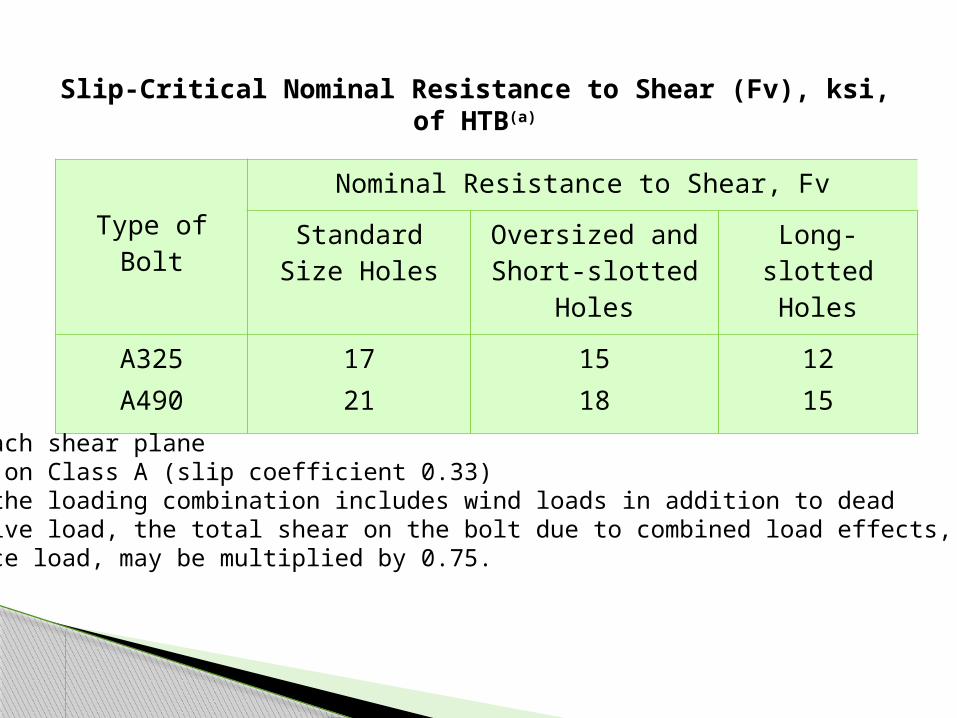
Slip-Critical Nominal Resistance to Shear (Fv), ksi, of HTB(a)
Type of BoltNominal Resistance to Shear, Fv
Standard Size Holes
Oversized and Short-slotted
Holes
Long-slotted Holes
A325A490
1721
1518
1215
(a) For each shear plane(b) Based on Class A (slip coefficient 0.33)(c) When the loading combination includes wind loads in addition to dead
and live load, the total shear on the bolt due to combined load effects, atservice load, may be multiplied by 0.75.

Slip resistance = Rn = m Du hsc Tb Ns
where, f = 1.0 for connections at serviceability limit = f 0.85 for connections at the required strength level.
m = mean slip coefficient for Class A or B surfaces= 0.35 for Class A surfaces (upainted clean mill scale)= 0.50 for Class B surfaces (unpainted blast cleaned surfaces
Du = 1.13 reflects the ratio of the mean installed bolt pretension
to the specified minimum bolt pretension.
hsc = hole factor
= 1.00 for STD, 0.85 for OVS and SSLT, 0.70 for LSLT)
Tb = minimum bolt tension given in Table J3.1
Ns = number of slip planes
Design Slip Resistance of SCBC : Rn

Table J3.1Minimum Bolt Tension (Tb), kips*
Bolt Size, in. A325 Bolts A490 Bolts
½ 5/8 ¾
7/8 1
11/8 11/4 13/8 11/2
12 19 28 39 51 56 71 85
103
15 24 35 49 64 80
102 121 148
*Equal to 0.70 of minimum tensile strength of bolts, rounded off to nearest kip, as specified in ASTM specifications for A325 and A490 bolts with UNC threads.

Splice plate
Splice plate
W8 x 28 W8 x 28
Splice plate
Splice plate
W8 x 28 W8 x 28
C.L.C.L.
Step I. Service loads = D + L = 200 kips.
Step II. Slip-critical splice connection, assume class A surface, Standard holes (STD)
fRn of one fully-tensioned slip-critical bolt = f 0.35x1.13x 1 x Tb Ns
If db = 7/8 in. From Table J.3.1 -- Tb=39kips
fRn of one bolt = 1.0 x 0.35 x 1.13 x 1.00 x 39 x 1 = 15.4 kips
fRn of n bolts = 15.4 x n > 200 kips (splice must be slip-critical at service)
Therefore, n > 13 Choose 16 fully tensioned 7/8 in. A325 bolts on each side of the splice
Example. Design a slip-critical splice for a tension member subjected to 300 kips of tension loading. The tension member is a W8 x 28 section made from A992 (50 ksi) material. The unfactored dead load is equal to 50 kips and the unfactored live load is equal to 150 kips. Use A325 bolts. The splice should be slip-critical at service loads.

Step III. Layout of splice connection Minimum edge distance (Le) = 1-1/8in. from Table J3.4 Design edge distance Le = 1.25 in. Minimum spacing = s = 2-2/3 db = 2.67 x 7/8 = 2.336 in. (Spec. J3.3) Preferred spacing = s = 3.0 db = 3.0 x 7/8 = 2.625 in. (Spec. J3.3) Design spacing = 3 inch
Step IV. Connection strength at factored loads =300kips The splice connection should be designed as a normal shear/bearing
connection Beam flange thickness : tf = 0.465 in and flange width bf = 6.535 in.
The shear strength of bolts = (0.75x48xAb) /bolt x 16 = 345.6 kips
Bearing strength at edge holes (Le = 1.25 in.) = 40.8 kips/in. thickness Bearing strength at non-edge holes (s = 3.0”) = 91.4 kips/in. thickness Bearing strength = 4 x 40.8 x 0.465 +12 x 91.3 x 0.465 = 673
kips
3 3 3 1.25
C.L.

Step V. Design the splice plate Tension yielding: 0.9 Ag Fy > 300 kips; Ag > 6.66 in2
Tension fracture: 0.75 An Fu > 300 kips
An =Ag - 4 x (7/8 +1/8) x t > 6.15 in.
Beam flange width = 6.535 in.Assume 6.5 in. wide splice plates with thickness = 0.75 in. The strength of the splice plate Yielding = 438.75 kips Fracture = 329 kips Check Block shear (Homework) Step VI. Check member strength (yield, fracture and block shear)

Kekuatan Geser :
ɸRn = 0.75 rt Fu Ab
dimana : Fu = Tegangan tarik ultimate (putus) dari bautrt = 0.5 untuk baut tanpa ulir pada bidang geser
= 0.4 untuk baut dengan ulir pada bidang geser Ab = luas area baut
Kekuatan TumpuUntuk Le > 1.5 db dan s > 3db
ɸRn = 0.75 2.4 db t Fu
Fu = Tegangan tarik ultimate (putus) terkecil antara baut dan pelat
Perhitungan Baut menurut SNI Baja 2002

Welded ConnectionStructural welding is a process wherein the parts to be connected are heatedand fused together, with supplementary molten metal added to the joint
(a) (b)
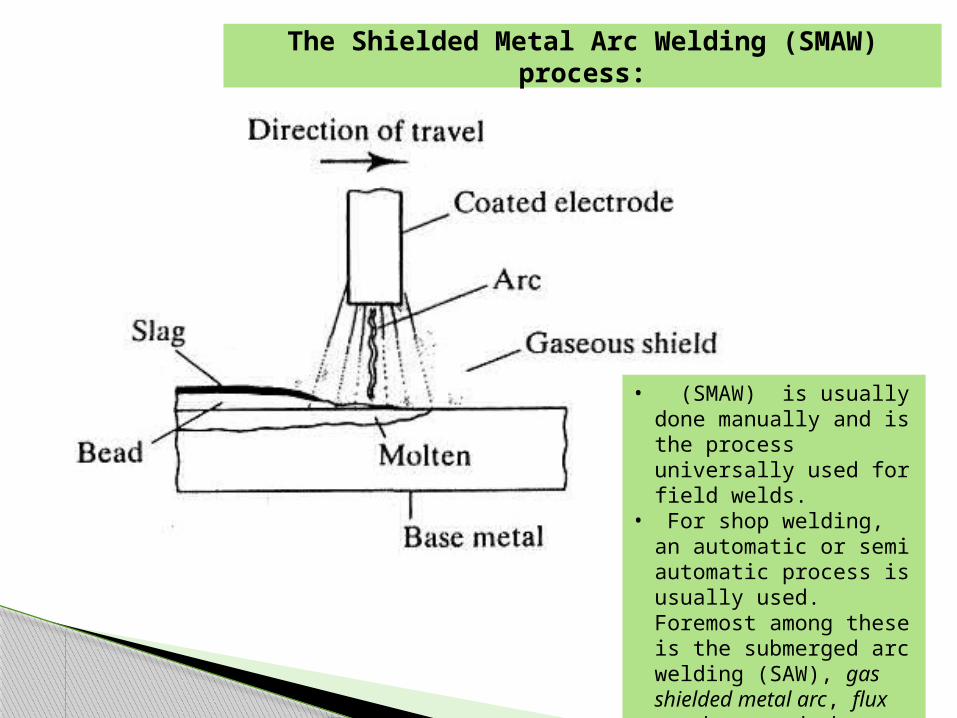
The Shielded Metal Arc Welding (SMAW) process:
• (SMAW) is usually done manually and is the process universally used for field welds.
• For shop welding, an automatic or semi automatic process is usually used. Foremost among these is the submerged arc welding (SAW), gas shielded metal arc, flux cored arc, and electro-slag welding

Types of welds:
(1) Fillet weld, which are defined as those placed in a corner formed by two
parts in contact. Example a lap joint & a tee joint.
(2) Groove weld, are those deposited in a gap, or groove, between two parts to be connected. They are most frequently used for butt, tee, and corner joints. In most cases, one or both of the connected parts will have beveled edges, called prepared edges, although relatively thin materials can be groove welded with no edge preparation.
Type: Complete penetration groove welds
Partial penetration groove welds.
(3) Plug or slot weld

Grooved welds

Fillet welds are most common and used in all structures. Weld sizes are specified in 1/16 in. increments A fillet weld can be loaded in any direction in shear,
compression, or tension. However, it always fails in shear.
Fillet Welds
Fillet weld
Fillet weld
Fillet weldFillet weld
Fillet weldFillet weld

Fillet Welds
Assumption the cross section (A) = Effective throat thickness 0.707 a x length L
The shear failure of the fillet weld occurs along a plane through the throat of the weld
a
a
Throat = a x cos45o
= 0.707 a
a
a
Throat = a x cos45o
= 0.707 a
Failure Plane
L

Failure mode : Shear
Critical Shear Strength:
The nominal load capacity:
The nominal Design Strength:
where Fw= the weld ultimate shear strength = 0.75
wLa
Pfv
707.0
wwn LafR 707.0
ww Laf 707.075.0R n

The ultimate shear strength of Fillet Weld: Fw
Fw depends on the weld metal used – that is, it is a function of the type
electrode.
Ultimate tensile strength of Electrode: 60, 70, 80, 90, and 110ksi. E60XX / E60 = an electrode with an ultimate tensile strength of 60 ksi. This is the standard terminology for weld electrodes
Electrodes should be selected to match the base metal:E70xx electrodes : for steels with Fy < 60 - 65 ksi
E80xx electrodes : for steels with Fy > 60 - 65 ksi. E70XX is the most popular electrode used for fillet welds made by the
SMAW method.
Fw in a fillet weld = 0.60 times the tensile strength of the weld metal,
denoted by FEXX.
The design stress: Fw = 0.60 FEXX ---- = 0.75. E70XX: Fw = 0.75 [0.60 (70)] = 31.5 ksi
E80XX: Fw = 0.75 [0.60 (80)] = 36 ksi

Fillet weld strength that account for load direction :
Fw = 0.6FExx (1.0 + 0.50 sin 1.5 θ)
Fw = 0.6 FExx is valid only if θ = 0 For weld with load perpendicular (θ = 90o ), the
strength is 50% higher
Effect of Load direction to Fw (AISC J2.4a) θ
axis of weld

AISC J2.4c specifies that the larger nominal strength from the following two options :
1. Use the basic strength for both : Rn = Rwl + Rwt
Rwl = Rwt = 0.6 FExx
2. Use the 50% higher of transverse welds but reduce the basic strength of longitudinal welds Rn = Rwl + Rwt
Rn = 0.85 (0.6 FExx ) + 1.5 (0.6 FExx)
Weld with both transversal & Longitudinal
Welding on both sides of gusset. L1 a
L2
2a
L3
(a)
(b)
(c)
Welding on both sides of gusset.Welding on both sides of gusset. L1 a
L2
2a
L3
L1 aL1 aL1 a
L2
2a
L2L2
2a
L3L3L3
(a)
(b)
(c)
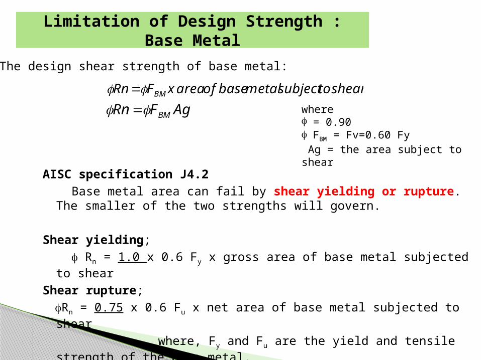
Limitation of Design Strength : Base Metal
The design shear strength of base metal:
sheartosubjectmetalbaseofareaxFRn BM
AgFRn BM where f = 0.90f FBM = Fv=0.60 Fy Ag = the area subject to shear
AISC specification J4.2 Base metal area can fail by shear yielding or rupture. The
smaller of the two strengths will govern.
Shear yielding; f Rn = 1.0 x 0.6 Fy x gross area of base metal subjected to shear
Shear rupture; fRn = 0.75 x 0.6 Fu x net area of base metal subjected to shear
where, Fy and Fu are the yield and tensile strength of the base metal.

T
ElevationPlan
T
ElevationPlan
Strength of weld in shear Strength of base metal
= 0.75 x 0.707 x a x Lw x fw = min {1.0 x 0.6 x Fy x t x Lw
0.75 x 0.6 x Fu x t x Lw}
Smaller governs the strength of the weld
Example :

NOTE : 1. Always check weld metal and base metal strength. Smaller
value governs. In most cases, the weld metal strength will govern.
2. In weld design problems, it is advantageous to work with strength per unit length of the weld or base metal.
t
Example:
The design strength of weld per inch of length:
Wn FxsizexR 707.0
The capacity of the bracket plate in shear per inch of length:
tFRn BM

Practical Considerations:
Minimum Size of Fillet Welds amin:
Material Thickness of Thicker Part Joined
(in.)
Minimum Size of Fillet Welds[a] (in.)
To ¼ inclusiveOver ¼ to ½Over ½ to ¾
Over 3/4
1/83/16
¼5/16
[a] Leg dimension of fillet welds. Single pass welds must be used.[b] See Section J2.2b for maximum size of fillet welds.

Maximum Size of fillet welds amax:- function of the thickness of the thickest connected plate:- plates with thickness 0.25 in., amax = t or 0.25 in. (the smallest).- plates with thickness 0.25 in., amax = t - 1/16 in.
Minimum Length of fillet welds Lw
- Lw 4 aotherwise aeff = Lw / 4- Intermittent fillet welds: Lw-min = 4 a and 1.5 in.End Returns:When a weld extends to the corner of a member, it must be continued aroundthe corner to avoid stress concentration.Length of end returns > two times the weld size. = 2a
The maximum size than can be made with a single pass of electrode is approximately 5/16 inch, and multiple passes will add to the cost.

Weld Symbols:
1/4 6
1/4 6
6
1/41/4
66
1/4 6
1/4 6E70
Near side (arrow side)
Other side
Both side
Weld all arround
Reference Field weld

Step I. Check the limitations
tmin = 3/8 in. (member)
tmax = 0.5 in. (gusset)
Then, amin = 3/16 in.
amax = 3/8 - 1/16 = 5/16in.
weld size = a = 1/4 in. OK!
Lw-min = 1.0 in.
Given length = 5.0 in. > Lmin. OK!
End returns :Min size = 2 a = 0.5 in. OK!
Example . Determine the design strength of the tension member and connection system shown below. The tension member is a 4 in. x 3/8 in. thick rectangular bar. It is welded to a 1/2 in. thick gusset plate using E70XX electrode. Consider the yielding and fracture of the tension member. Consider the shear strength of the weld metal and the surrounding base metal.
5 in.
5 in.
0.5 in.
0.5 in.
4 in x 3/8 in.
t = 0.5 in.
a = 0.25 in.
5 in.
5 in.
0.5 in.
0.5 in.
4 in x 3/8 in.
t = 0.5 in.
a = 0.25 in.
Step II. Design strength of the weldWeld strength = f x 0.707 x a x 0.60 x FEXX x Lw
= 0.75 x 0.707 x 0.25 x 0.60 x 70 x 10 = 55.67 kips

Step II. Design strength of the weldBase Metal strength = min { f x 0.6 x Fy x Lw x t ; f x 0.6 x Fu x Lw x t}
= min {1.0 x 0.6 x 50 x 10 x 3/8 ; 0.75 x 0.6 x 65 x 10 x 3/8}
= min {112.5 ; 109.7 kips} = 109.7 kips
Step III. Tension strength of the memberf Rn = 0.9 x 50 x 4 x 3/8 = 67.5 kips - tension yield
f Rn = 0.75 x Ae x 65 - tension fracture
Ae = U A
A = Ag = 4 x 3/8 = 1.5 in2
U = 0.75 , since connection length (Lconn) < 1.5 w
Therefore, fRn = 54.8 kips
The design strength of the member-connection system = 54.8 kips. Tension fracture of the member governs. The end returns at the corners were not included in the calculations.

Step I. Assume material properties : Fy= 36ksi for member & gusset plates and E70XX electrode for the fillet welds.Step II. Design the tension memberSelect 2L 5 x 3½ x 1/2 made from 36 ksi steel.Yield strength = 260 kips Fracture strength = 261 kips.
Step III. Design the welded connectionamin = 3/16 in. amax = 1/2 - 1/16 in. = 7/16 in.
Design, a = 3/8 in. = 0.375 in.
Shear strength of weld metal = fRn = 0.75 x 0.60 x FEXX x 0.707 x a x Lw
= 8.35 Lw kips
Strength of the base metal in shear = min {1.0 x 0.6 x Fy x t x Lw ; 0.75 x 0.6 x Fu x t x Lw}
min { 10.8 Lw ; 14.62 Lw} kips
Shear strength of weld metal governs, f Rn = 8.35 Lw kips
f Rn > 250 kips 8.35 Lw > 250 kips
Lw > 29.94 in.
use Lw = 30.0 in.
Example. Design a double angle tension member and connection system to carry a factored load of 250 kips.

Step IV. Layout of Connection
Welding on both sides of gusset. L1 a
L2
2a
L3
(a)
(b)
(c)
Welding on both sides of gusset.Welding on both sides of gusset. L1 a
L2
2a
L3
L1 aL1 aL1 a
L2
2a
L2L2
2a
L3L3L3
(a)
(b)
(c)
Lw= 30 in. for two anglesAssume Lw for each = 15.0 in. E70XX fillet weld can be placed in three ways (a), (b), and (c).

AISC Spec. requires that the fillet weld terminate at a distance greater than the size (1/2 in.) of the weld. For this option, L1 will be equal to 7.5 in.
The fillet weld can be returned continuously around the corner for a distance of at least 2 a (1 in.).
L2 can be either 6.5 in. or 7.5 in. However, the value of 7.5 in. is preferred.
L3 will be equal to 5.75 in.
Welding on both sides of gusset. L1 a
L2
2a
L3
(a)
(b)
(c)
Welding on both sides of gusset.Welding on both sides of gusset. L1 a
L2
2a
L3
L1 aL1 aL1 a
L2
2a
L2L2
2a
L3L3L3
(a)
(b)
(c)
Step IV. Layout of Connection

Step V. Fracture strength of the memberAe = U Ag
U = 1- x/L Asssume case a ------ U = 1-0.901/7.5 = 0.88 0.9 f Rn = 0.75 x 0.88 x 8.00 x 58 = 306.24 kips > 250 kips OK
Step VI. Design the gusset plate f Rn > Tu
Tension yielding limit state0.9 x Ag x 36 > 250 kips Ag > 7.71 in2
Tension fracture limit state0.75 x An x Fu > 250 kips AISC specification An 0.85 Ag
An > 5.747 in2 Ag > 6.76 in2
Design gusset plate : thickness = 1.0 in. width = 8.0 in.
1/2 7.5 in. (a)1/2 7.5 in.
1/2 7.5 in.1/2 7.5 in.
Gusset plate 8 x ½ in.
Two 5 x 3.5 x 1/2 in
1/2 7.5 in. (a)1/2 7.5 in.
1/2 7.5 in.1/2 7.5 in.
Gusset plate 8 x ½ in.
Two 5 x 3.5 x 1/2 in

Sambungan Baut : 7.4.4 ; 7.4.6 ;
Sambungan Las : 7.11.2; 7.11.4
PR

![Behavior of bolted angle connections subjected to combined ...daryanpub.com/userfiles/file/Articles/sdarticle2.pdf · welded moment connections of steel frames [1,2]. Since then,](https://img.dokumen.tips/doc/110x75/5e9942a22ea80b5629071f77/behavior-of-bolted-angle-connections-subjected-to-combined-welded-moment-connections.jpg)


![Bolted Connections[1]](https://img.dokumen.tips/doc/110x75/54e7f8c84a7959704f8b46b8/bolted-connections1.jpg)
