Embed Size (px)
Citation preview
KENYA STANDARD KS 574:2017
Steel fabric for reinforcement of concrete — Specification
© KEBS 2017 FifthEdition 2017
KS 574:2017
ii KEBS 2015 — All rights reserved
TECHNICAL COMMITTEE REPRESENTATION
The following organizations were represented on the Technical Committee:
1. Architectural association of Kenya
2. Blue Nile group of companies
3. Brollo Kenya Limited
4. Consumer Information Network
5. Dedan Kimathi University Of Technology\
6. Devki Steel Mill Ltd
7. Doshi & co(H) Ltd
8. Howard Humphreys
9. Insteel Limited
10. Kenya Association of manufacturers
11. Kenya Institute of Research and development
12. Kenya National Accreditation Services
13. Nails and Steel Products
14. National Housing Corporation
15. Palak international limited
16. Steel Makers Ltd
17. Tononoka Steels
18. University of Nairobi
19. Kenya Bureau of Standards — Secretariat
REVISION OF KENYA STANDARDS In order to keep abreast of progress in industry, Kenya Standards shall be regularly reviewed. Suggestions for improvements to published standards, addressed to the Managing Director, Kenya Bureau of Standards, are welcome.
© Kenya Bureau of Standards, 2017 Copyright. Users are reminded that by virtue of Section 25 of the Copyright Act, Cap. 12 of 2001 of the Laws of Kenya, copyright subsists in all Kenya Standards and except as provided under Section 26 of this Act, no Kenya Standard produced by Kenya Bureau of Standards may be reproduced, stored in a retrieval system in any form or transmitted by any means without prior permission in writing from the Managing Director.
KENYA STANDARD KS 574:2017
KEBS 2015 — All rights reserved iii
Steel fabric for reinforcement of concrete — Specification
KENYA BUREAU OF STANDARDS (KEBS)
Head Office: P.O. Box 54974, Nairobi-00200, Tel.: (+254 020) 605490, 602350, Fax: (+254 020) 604031 E-Mail: [email protected], Web:http://www.kebs.org
Coast Region Lake Region Rift Valley Region
P.O. Box 99376, Mombasa-80100 P.O. Box 2949, Kisumu-40100 P.O. Box 2138, Nakuru-20100
Tel.: (+254 041) 229563, 230939/40 Tel.: (+254 057) 23549, 22396 Tel.: (+254 051) 210553, 210555 Fax: (+254 041) 229448 Fax: (+254 057) 21814
KS 574:2017
iv KEBS 2015 — All rights reserved
Foreword This Kenya Standard was prepared by the Steel Technical Committee under the guidance of the Standards Projects Committee and it is in accordance with the procedures of the Kenya Bureau of Standards. Steel fabric is widely used in the country in the reinforcement of concrete, and there exists a great potential for its development and use. This standard lays down the specifications of such fabrics and emphasis was laid on the metrication of the meshes. This fourth edition of KS 574 has incorporated more reference meshes and width measurements to broaden its scope. Additional illustrations were also included during the revision of this standard. This fourth edition of KS 574:2015 cancels and replaces the third edition of KS 574:2014, Steel fabric for reinforcement of concrete — Specification. During the preparation of this standard, reference was made to the following documents:
BS 4483:2005: Specification for steel fabric for the reinforcement of concrete.
IS 1566:1967 Hard drawn steel wire fabric for concrete reinforcement.
MS 145:2001, Specification for steel welded fabric for the reinforcement of concrete (second revision).
KS 574:2014, Steel fabric for reinforcement of concrete — Specification.
Acknowledgement is hereby made for the assistance derived from these sources.
KENYA STANDARD KS 574:2017
KEBS 2015 — All rights reserved 1
Steel fabric for reinforcement of concrete — Specification
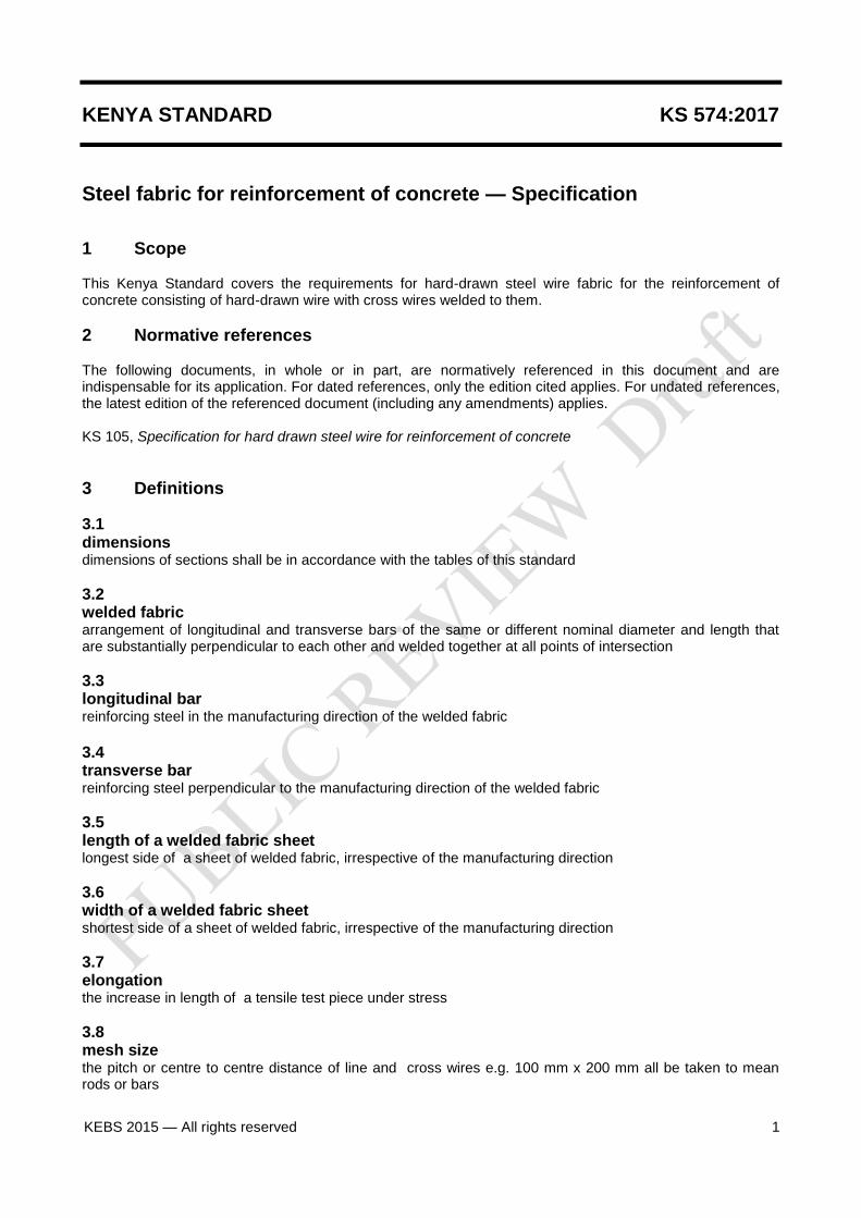
1 Scope This Kenya Standard covers the requirements for hard-drawn steel wire fabric for the reinforcement of concrete consisting of hard-drawn wire with cross wires welded to them.
2 Normative references The following documents, in whole or in part, are normatively referenced in this document and are indispensable for its application. For dated references, only the edition cited applies. For undated references, the latest edition of the referenced document (including any amendments) applies. KS 105, Specification for hard drawn steel wire for reinforcement of concrete
3 Definitions
3.1 dimensions dimensions of sections shall be in accordance with the tables of this standard
3.2 welded fabric arrangement of longitudinal and transverse bars of the same or different nominal diameter and length that are substantially perpendicular to each other and welded together at all points of intersection
3.3 longitudinal bar reinforcing steel in the manufacturing direction of the welded fabric
3.4 transverse bar reinforcing steel perpendicular to the manufacturing direction of the welded fabric
3.5 length of a welded fabric sheet longest side of a sheet of welded fabric, irrespective of the manufacturing direction
3.6 width of a welded fabric sheet shortest side of a sheet of welded fabric, irrespective of the manufacturing direction
3.7 elongation the increase in length of a tensile test piece under stress
3.8 mesh size the pitch or centre to centre distance of line and cross wires e.g. 100 mm x 200 mm all be taken to mean rods or bars
2 KEBS 2015 — All rights reserved
4 Types Hard-drawn steel wire fabric shall be of the following four types: i) square mesh; ii) structural fabric; iii) long mesh; iv) wrapping fabric.
5 Designations and description for ordering purposes When ordering fabric to this standard, the purchaser shall give the following requirements in the same sequence: i) the reference number of fabric; and ii) the number and size of sheets or rolls.
6 Quality of steel All fabric shall be manufactured from hard-drawn steel wire in accordance with KS 02-105.
7 Manufacture and design
7.1 Structure The fabric shall be formed by spacing the main and the cross wires, which shall be fixed at points of inter-section by fusion electric welding or interweaving, so as to be sufficiently stable to withstand normal handling while in transit and during concreting, without displacement.
7.2 Joints Butt joints in the wires of the fabric shall be electrically welded and the joints shall be staggered.
8 Condition of finished fabric All fabric reinforcement shall be delivered free from loose mill scale, loose rust, oil and grease and other extraneous matter likely to affect the bond with concrete adversely. The sheet or roll shall not contain any broken wires, and the number of broken cross-welded joints shall not exceed 4 % of the total number of cross welded joints, nor exceed half the cross-welded joint along any one wire
9 Dimensions and mass
9.1 Dimensions The preferred mesh sizes, wire sizes and mass per square metre shall be as given in Tables 2, 3, 4 and 5.
9.2 Calculation of mass The nominal mass of fabric shall be calculated on the basis that a metre length of steel weighs 0.00785 kg/mm
2..
10 Tolerances
10.1 Mesh size
KS 574:2015
KEBS 2015 — All rights reserved 3
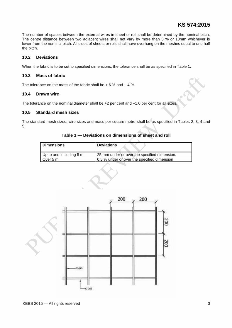
The number of spaces between the external wires in sheet or roll shall be determined by the nominal pitch. The centre distance between two adjacent wires shall not vary by more than 5 % or 10mm whichever is lower from the nominal pitch. All sides of sheets or rolls shall have overhang on the meshes equal to one half the pitch.
10.2 Deviations When the fabric is to be cut to specified dimensions, the tolerance shall be as specified in Table 1.
10.3 Mass of fabric The tolerance on the mass of the fabric shall be + 6 % and – 4 %.
10.4 Drawn wire The tolerance on the nominal diameter shall be +2 per cent and –1.0 per cent for all sizes.
10.5 Standard mesh sizes The standard mesh sizes, wire sizes and mass per square metre shall be as specified in Tables 2, 3, 4 and 5.
Table 1 — Deviations on dimensions of sheet and roll
Dimensions
Deviations
Up to and including 5 m 25 mm under or over the specified dimension.
Over 5 m 0.5 % under or over the specified dimension
4 KEBS 2015 — All rights reserved
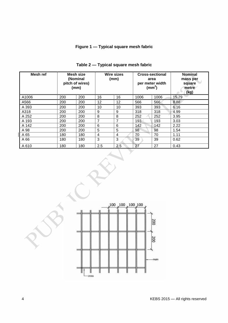
Figure 1 — Typical square mesh fabric
Table 2 — Typical square mesh fabric
Mesh ref Mesh size (Nominal
pitch of wires) (mm)
Wire sizes (mm)
Cross-sectional area
per meter width (mm
2)
Nominal mass per square metre (kg)
A1006 200 200 16 16 1006 1006 15.79
A566 200 200 12 12 566 566 8.88
A 393 200 200 10 10 393 393 6.16
A318 200 200 9 9 318 318 4.99
A 252 200 200 8 8 252 252 3.95
A 193 200 200 7 7 193 193 3.03
A 142 200 200 6 6 142 142 2.22
A 98 200 200 5 5 98 98 1.54
A 65 180 180 4 4 70 70 1.11
A 66 180 180 3 3 39 39 0.62
A 610 180 180 2.5 2.5 27 27 0.43
KS 574:2015
KEBS 2015 — All rights reserved 5
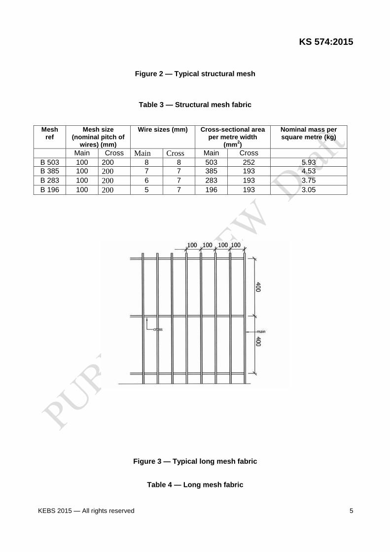
Figure 2 — Typical structural mesh
Table 3 — Structural mesh fabric
Mesh ref
Mesh size (nominal pitch of
wires) (mm)
Wire sizes (mm) Cross-sectional area per metre width
(mm2)
Nominal mass per square metre (kg)
Main Cross Main Cross Main Cross
B 503 100 200 8 8 503 252 5.93
B 385 100 200 7 7 385 193 4.53
B 283 100 200 6 7 283 193 3.75
B 196 100 200 5 7 196 193 3.05
Figure 3 — Typical long mesh fabric
Table 4 — Long mesh fabric
6 KEBS 2015 — All rights reserved
Mesh ref Mesh size (Nominal
pitch of wires) (mm)
Wire sizes (mm)
Cross-sectional area
per meter width (mm
2)
Nominal mass per square metre (kg)
main cross main cross main cross
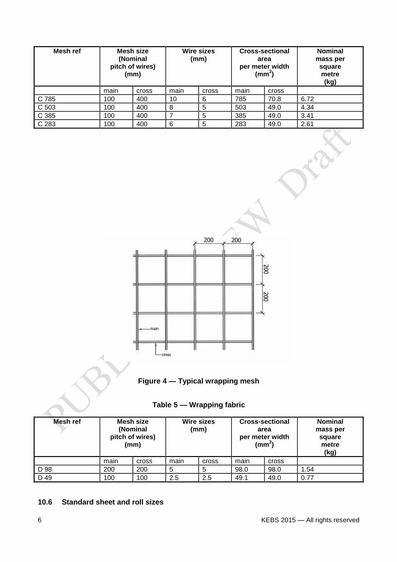
C 785 100 400 10 6 785 70.8 6.72
C 503 100 400 8 5 503 49.0 4.34
C 385 100 400 7 5 385 49.0 3.41
C 283 100 400 6 5 283 49.0 2.61
Figure 4 — Typical wrapping mesh
Table 5 — Wrapping fabric
Mesh ref Mesh size (Nominal
pitch of wires) (mm)
Wire sizes (mm)
Cross-sectional area
per meter width (mm
2)
Nominal mass per square metre (kg)
main cross main cross main cross
D 98 200 200 5 5 98.0 98.0 1.54
D 49 100 100 2.5 2.5 49.1 49.0 0.77
10.6 Standard sheet and roll sizes
KS 574:2015
KEBS 2015 — All rights reserved 7
The sheet and roll sizes of fabrics shall be as specified in Table 6.
Table 6 — Sheet and roll sizes Length Width of sheet or
roll
Sheet of 4.2 m 2.1m or 2.4m Roll of 24m and 48m 2.1m or 2.4m
10.7 Measurement of length/width of sheet or roll The length/width of sheet or roll shall be measured from the tops of the overhangs.
11 Strength of weld The manufacturers shall certify that where the inter-sections are welded when tested in accordance with Clause 12, all such welds shall be capable of withstanding a load in a shear of not less than one quarter of that necessary to develop the load, calculated from the specified characteristic proof stress in tension, of the smaller intersecting wires. This certification shall not be invalidated by broken welds provided they are within the limits specified in Clause 7.
12 Tests Test pieces for tensions and bend tests shall be so cut, from the fabric that each tensile test piece shall contain one or more cross welds in its length.
12.1 Tensile test 12.1.1 Tensile tests shall be made on the mesh after fabrication across one or more welds to the requirements specified in ISO 6892-1: 2016 12.1.2 One tensile test shall be made for every 6 000m
2 of fabric.
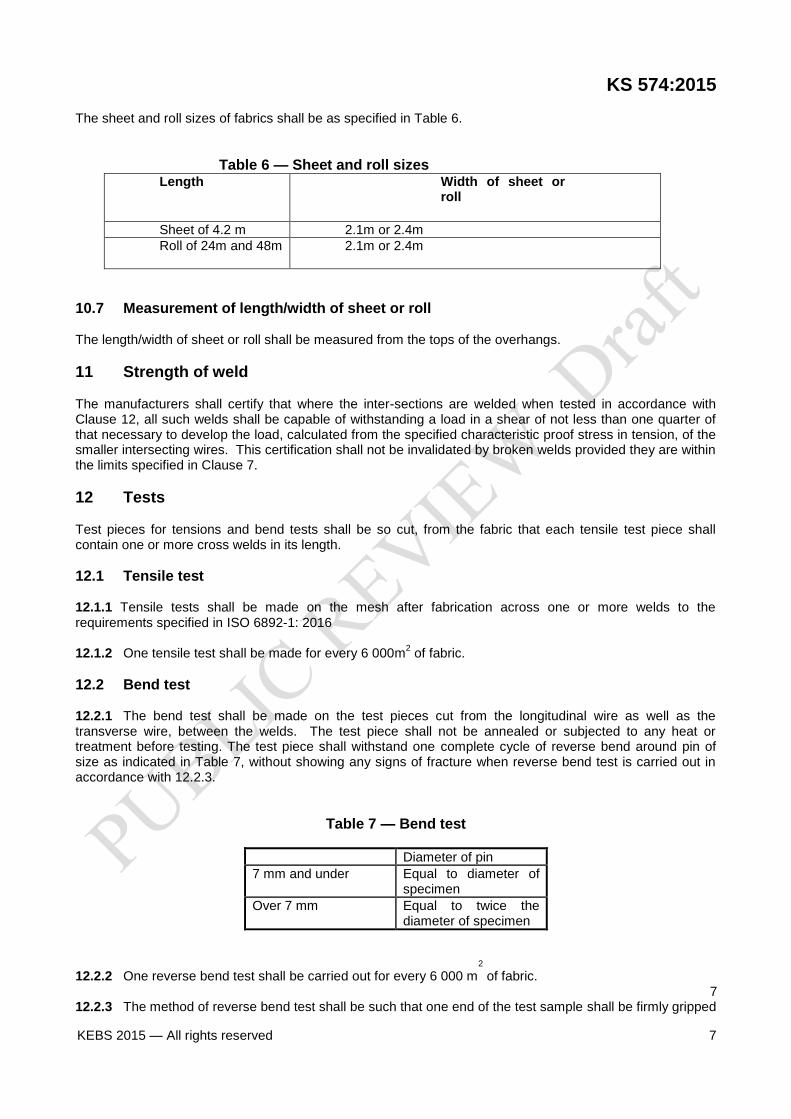
12.2 Bend test 12.2.1 The bend test shall be made on the test pieces cut from the longitudinal wire as well as the transverse wire, between the welds. The test piece shall not be annealed or subjected to any heat or treatment before testing. The test piece shall withstand one complete cycle of reverse bend around pin of size as indicated in Table 7, without showing any signs of fracture when reverse bend test is carried out in accordance with 12.2.3.
Table 7 — Bend test
Diameter of pin
7 mm and under Equal to diameter of specimen
Over 7 mm Equal to twice the diameter of specimen
12.2.2 One reverse bend test shall be carried out for every 6 000 m2
of fabric. 7
12.2.3 The method of reverse bend test shall be such that one end of the test sample shall be firmly gripped
8 KEBS 2015 — All rights reserved
in a vice and the free end shall be bent round a pin of diameter as in 12.2.1 above, through an angle of 90° and bent back in the opposite direction round the same radius through an angle of 180°, thereafter being bent back again to the original position without fracture.
12.3 Retest Should a tensile test piece break outside the middle half of the gauge length, the test may be discarded and another test made on a piece cut from the same length of wire. In all other cases, should any of the test pieces first selected not fulfill the required test, two additional tests pieces in respect of each failure may be taken. Should both the additional test pieces pass the test, the material shall be deemed to comply with this standard. Should either of them fail to fulfill such tests, the material represented shall be rejected. The additional test shall be carried out in the same manner in all respects as the tests previously carried out.
13 Shear test
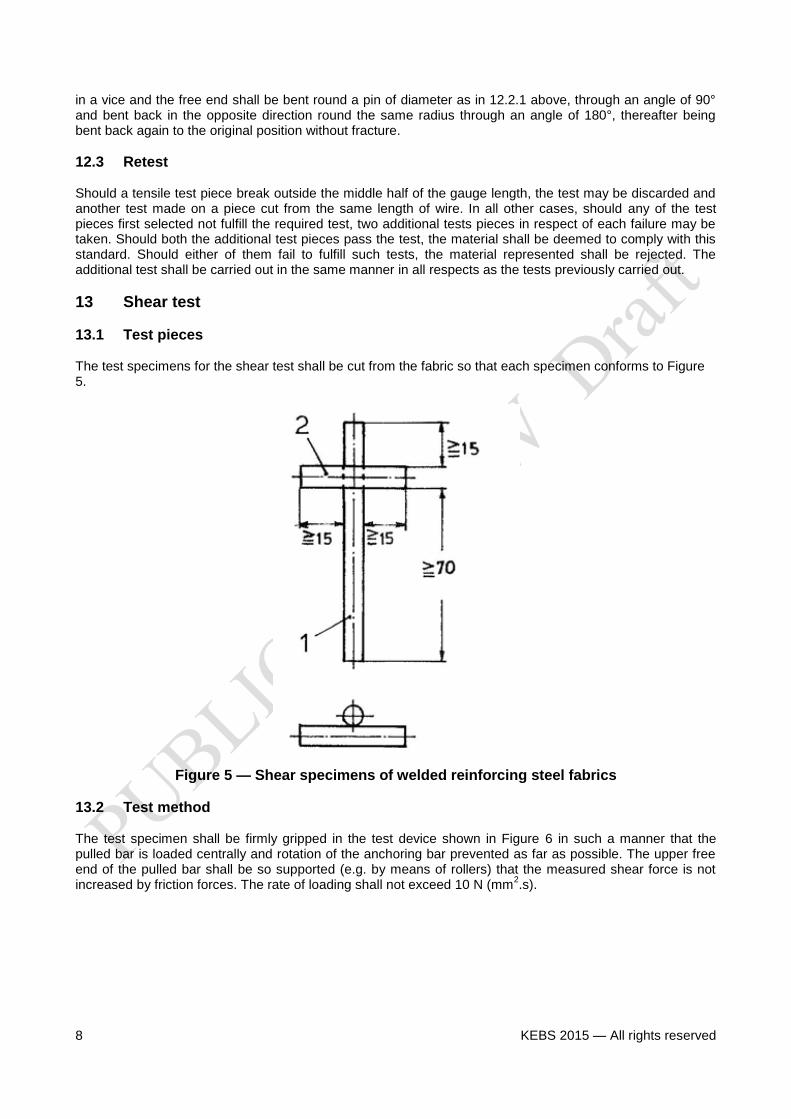
13.1 Test pieces The test specimens for the shear test shall be cut from the fabric so that each specimen conforms to Figure 5.
Figure 5 — Shear specimens of welded reinforcing steel fabrics
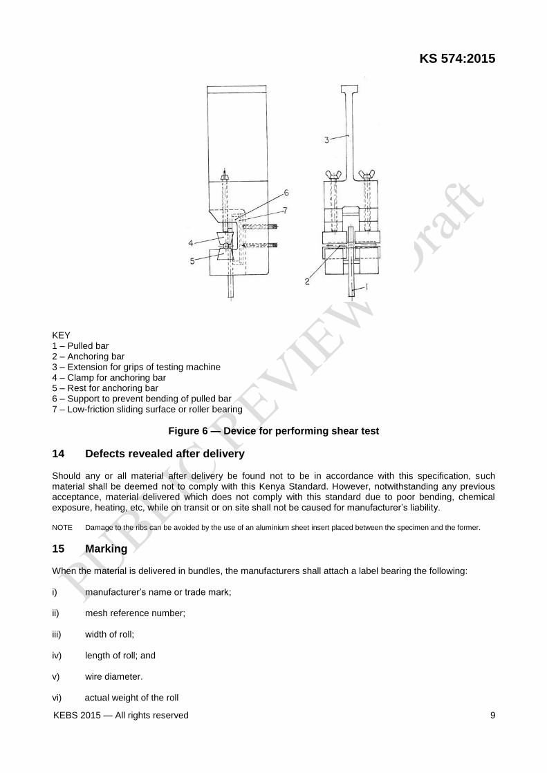
13.2 Test method The test specimen shall be firmly gripped in the test device shown in Figure 6 in such a manner that the pulled bar is loaded centrally and rotation of the anchoring bar prevented as far as possible. The upper free end of the pulled bar shall be so supported (e.g. by means of rollers) that the measured shear force is not increased by friction forces. The rate of loading shall not exceed 10 N (mm
2.s).
KS 574:2015
KEBS 2015 — All rights reserved 9
KEY 1 – Pulled bar 2 – Anchoring bar 3 – Extension for grips of testing machine 4 – Clamp for anchoring bar 5 – Rest for anchoring bar 6 – Support to prevent bending of pulled bar 7 – Low-friction sliding surface or roller bearing
Figure 6 — Device for performing shear test
14 Defects revealed after delivery Should any or all material after delivery be found not to be in accordance with this specification, such material shall be deemed not to comply with this Kenya Standard. However, notwithstanding any previous acceptance, material delivered which does not comply with this standard due to poor bending, chemical exposure, heating, etc, while on transit or on site shall not be caused for manufacturer’s liability. NOTE Damage to the ribs can be avoided by the use of an aluminium sheet insert placed between the specimen and the former.
15 Marking When the material is delivered in bundles, the manufacturers shall attach a label bearing the following: i) manufacturer’s name or trade mark; ii) mesh reference number; iii) width of roll; iv) length of roll; and v) wire diameter. vi) actual weight of the roll