Embed Size (px)
Citation preview

71
STEEL DESIGN +
G.W. Butcher *
ABSTRACT
Structural steel has proved to be a suitable material for ductile moment-resisting space frames in buildings subjected to strong earthquake ground motion.
The material properties buckling criteria and connection design considered necessary to avoid premature unloading before the inelastic potential of the material is achieved are discussed. Consideration is also given to the behaviour of full size steel frames, lamellar tearing and deformation of the panel zone,
1, INTRODUCTION
The paper deals with multi-storey steel moment-resisting space frames of conventional type.
As with frames of other materials subjected to seismic loadings, economy requires that the energy-absorption and dissipation capacity of the system be fully utilised as the basis of design, rather than criteria of strength alone. Energy dissipation is achieved by the ability to deform well into the inelastic range. Current methods of design of multi-storey structures are based upon the strong column-weak beam concept. This postulates that the survival of a building during an earthquake depends largely upon the ability of the beams and joints to dissipate energy by inelastic action while the columns in the main remain elastic.
In a single earthquake the number of excursions into the inelastic range may be of the order of 10 to 15. The action of alternating plasticity on members under such behaviour is one of low cycle fatigue.
2. PERFORMANCE OF STRUCTURAL STEEL FRAMED BUILDINGS
The performance of structural steel framed buildings in past earthquakes has been particularly good. In many cases steel frames with partial moment-resisting connections have remained intact or suffered little damage even when the main lateral force resisting elements such as reinforced concrete shear walls or cores have failed.
Experience with particular earthquakes is as follows:
+ This paper was originally presented at the Seminar "Structural Design for Earthquakes" held at the University of Auckland in August 1972.
* Consulting Engineer, Wellington
San Francisco 1906 M = 8.25
Most of the tall buildings in the city consisted of steel framed structures supporting all wall and floor loads. They were probably the most exposed to earthquake damage.
The height distribution of buildings with structural steel frames was as follows:
6 - 1 0 storeys 11 No. (three under construction)
11 - 15 storeys 8 No. 16 - 19 storeys 2 No. (one under
construction)
Floor areas ranged from 100 0 square feet to 66,000 square feet, walls were of stone, terra cotta and brick. Most of the buildings were hotels or offices. Some of the structures were well braced for wind by diagonal bracing or moment-resisting frames or a combination but those large in area had no special wind bracing.
The r e p o r t ^ on the earthquake states that the damage to steel frames was almost negligible. Damage consisted of some sheared bolts and rivets and bent diagonal bracing. There was considerable damage to partitions and to stone and brickwork.
Anchorage-Alaska 1964 M = 8.4
There were no tall steel framed buildings in the Anchorage area at the time of the earthquake.
Those buildings with steel frames up to 5 storeys in height performed well with little or no significant structural damage. Minor cracking occurred in stairwells. Other typical damage was bending of light angle members in trusses and framing in industrial structures deformed holding down bolts and failures of diagonal bracing connections.
The steel framed buildings above five storeys had frames which'were designed for gravity loads only (apart from the frame of the Cordova Building in the East-West direction) and had simple or partial moment-resisting connections. Resistance to lateral loads was provided by reinforced concrete shear walls or cores. Damage to steel frames was slight except for a few ground to first floor columns in the Cordova Building which were effected by poor design details.
A feature of the damage in Anchorage was, the ability of structural steel frames designed for gravity loads only to retain the structural integrity of the building even after the lateral resisting elements had failed thus providing a "second line of seismic
Bulletin of the N.2. Society for Earthquake Engineering, Vol. 6, No. 2, June, 1973.

resistance". (2) This desirable characteristic occurred even in frames designed with simple or partial moment-resisting connections.
Caracas 1967 M = 6.5
There were a few steel framed multi-storey buildings in Caracas at the time of the earthquake including the twin 30 storey towers of the Simon Bolivar Center. No significant damage
(3) was suffered by these structures.
3. MATERIALS Structural steels for ductile moment-resist
ing space frames should be those accepted as suitable for plastic design. Consideration should also be given to properties such as weldability, 'cleanness 1 of steel and resistance to brittle fracture. Weldability and brittle fractures have been treated elsewhere and will not be discussed further in this paper.
ISE/WI Second Report May 1971 (6) 72
Steels for structural use have been classified by the Column Research Council in the following broad types and strength indices.
( 4 )
TYPE OF STEEL
1. Structural Carbon Steels
2. High Strength Group (A) Manganese-Copper
Group (B) Manganese-Vanadium
STRENGTH INDEX
Up to 42 KSI Inclusive
43-55 KSI
43-55 KSI
Group (C) Multiple Alloy 43-55 KSI
Group (D) Columbium or Vanadium
Heat Treated Carbon Steels
Heat Treated Alloy Steels
56-75 KSI Up to 42 KSI ) 43-55 KSI ) 56-75 KSI ) 56-75 KSI 76-100 KSI 56-75 KSI 76-100 KSI
101 and over
EXAMPLES
ASTM A36
ASTM A440
ASTM A441
ASTM A242 US COR-TEN A
ASTM A588 US COR-TEN B US COR-TEN C
ASTM A572
ASTM A537
ASTM A514 UST1
USHY13
Steels accepted as suitable for plastic design are generally those of Type 1 Structural Carbon Steels and Type 2 High Strength and Low Alloy Steels. It should be emphasised that at this stage of development of plastic design methods, heated treated steels of Type 3 and 4 have not been included.
1. Structural Steels Suitable for Plastic Design AISC Specification February 1969 Part 2 (5)
ASTM A36 A242 A441 A529 A572 A588
Steel of any yield point up to and including 65 KSI (29 tons/sq.in.)
2. Structural Steels suitable for Ductile Moment-Resisting Space Frames
SEOC 1968 Revision
ASTM A36 A440 . A441 A572 Except grades 60 and 65 A588 Grades A B or C
Note that weathering steels are suitable.
Important discoveries such as steels with Yield Stress/Ultimate Tensile Strength ratios .approaching 1 but with exceptionally high fracture toughness and ductility not associated with such steels by conventional measures of ductility are likely to extend the range of steels available.
Future trends in metallurgical control will be towards production of steels with uniform mechanical properties independent.of the thickness range and with stricter control on non metallic inclusions.
From the structural design viewpoint consistency of mechanical properties and welding characteristics and not chemistry are important.
Tests have already shown the beneficial effects of vacuum treatments in steelmaking such as vacuum degassing and vacuum arc melting on the fatigue life of steels and particularly low cycle fatigue.
Precipitates or inclusions can initiate cracks which in subsequent cyclic stressing propagate and lead to failure.
4. FRAME ELEMENTS
A ductile moment-resisting space frame consists of beams, columns and connections common to both. Current design criteria requires only elastic action in the columns with the beams and joints dissipating energy by inelastic action.
The contribution of the frame elements to interstorey deflection at mid-height of a 40 storey steel framed building has been shown by Teal to be as follows
Girder
59%
Column
15%
Joint
26%
In this case shear contributed 80% and column shortening 20% to the total interstorey deflection. The importance of the joint in the total deflection should not be overlooked.
4.1 Beams
Beams in a frame are essentially loaded in a manner which produces bending about the major axis and shear. Usually axial loads are small and may be neglected.
The simple plastic theory of bending is basically a limiting strength theory based upon the likely failure of the structure under
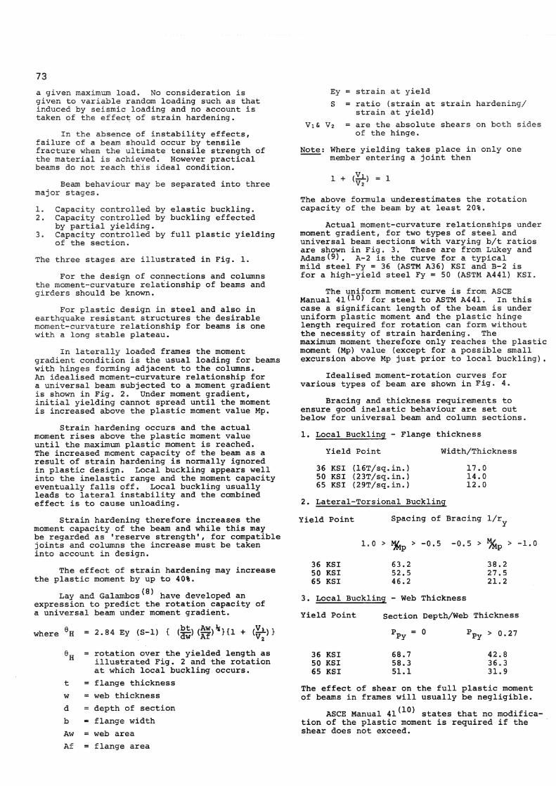
73 a given maximum load. No consideration is given to variable random loading such as that induced by seismic loading and no account is taken of the effect of strain hardening.
In the absence of instability effects, failure of a beam should occur by tensile fracture when the ultimate tensile strength of the material is achieved. However practical beams do not reach this ideal condition.
Beam behaviour may be separated into three major stages.
1. Capacity controlled by elastic buckling. 2. Capacity controlled by buckling effected
by partial yielding. 3. Capacity controlled by full plastic yielding
of the section.
The three stages are illustrated in Fig. 1.
For the design of connections and columns the moment-curvature relationship of beams and girders should be known.
For plastic design in steel and also in earthquake resistant structures the desirable moment-curvature relationship for beams is one with a long stable plateau.
In laterally loaded frames the moment gradient condition is the usual loading for beams with hinges forming adjacent to the columns. An idealised moment-curvature relationship for a universal beam subjected to a moment gradient is shown in Fig. 2. Under moment gradient, initial yielding cannot spread until the moment is increased above the plastic moment value Mp.
Strain hardening occurs and the actual moment rises above the plastic moment value until the maximum plastic moment is reached. The increased moment capacity of the beam as a result of strain hardening is normally ignored in plastic design. Local buckling appears well into the inelastic range and the moment capacity eventually falls off. Local buckling usually leads to lateral instability and the combined effect is to cause unloading.
Strain hardening therefore increases the moment capacity of the beam and while this may be regarded as 'reserve strength 1, for compatible joints and columns the increase must be taken into account in design.
The effect of strain hardening may increase the plastic moment by up to 40%.
(8) Lay and Galambos have developed an
expression to predict the rotation capacity of a universal beam under moment gradient.
where H 2 . 8 4 Ey (S-l) { (|§) ( g ) * H l lV 2' J
Ey = strain at yield S = ratio (strain at strain hardening/
strain at yield) Vi& V2 = are the absolute shears on both sides
of the hinge.
Note: Where yielding takes place in only one member entering a joint then
1 + <^-> = 1
The above formula underestimates the rotation capacity of the beam by at least 20%.
Actual moment-curvature relationships under moment gradient, for two types of steel and universal beam sections with varying b/t ratios are shown in Fig. 3. These are from Lukey and AdamsO ) . A-2 is the curve for a typical mild steel Fy = 36 (ASTM A36) KSI and B-2 is for a high-yield steel Fy = 50 (ASTM A441) KSI.
The uniform moment curve is from ASCE Manual 41< 1 0) for steel to ASTM A441. In this case a significant length of the beam is under uniform plastic moment and the plastic hinge length required for rotation can form without the necessity of strain hardening. The maximum moment therefore only reaches the plastic moment (Mp) value (except for a possible small excursion above Mp just prior to local buckling).
Idealised moment-rotation curves for various types of beam are shown in Fig. 4.
Bracing and thickness requirements to ensure good inelastic behaviour are set out below for universal beam and column sections.
1. Local Buckling - Flange thickness
Yield Point Width/Thickness
36 KSI (16T/sq.in.) 50 KSI (23T/sq.in.) 65 KSI (29T/sq.in.)
17.0 14.0 12.0
2. Lateral-Torsional Buckling
Yield Point Spacing of Bracing 1/r
1.0 > % > -0.5 -0.5 > % p > -1.0
36 KSI 50 KSI 65 KSI
63.2 52.5 46.2
38.2 27.5 21.2
3. Local Buckling - Web Thickness
Yield Point Section Depth/Web Thickness
P p y > 0.27
t w d b Aw Af
= rotation over the yielded length as illustrated Fig. 2 and the rotation at which local buckling occurs.
= flange thickness = web thickness = depth of section - flange width = web area = flange area
36 KSI 50 KSI 65 KSI
68.7 58.3 51.1
42.8 36.3 31.9
The effect of shear on the full plastic moment of beams in frames will usually be negligible.
ASCE Manual 4 1 ^ * ^ states that no modification of the plastic moment is required if the shear does not exceed.

74
£Z w - d ay = yield stress /5* w w = web thickness
d w = clear depth of web.
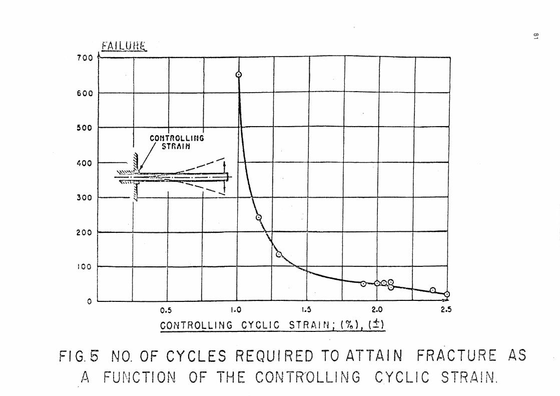
Beams in a frame responding to earthquake ground motion are subjected to load reversals which cause alternating plastic strains in bending. This may occur several times in an earthquake with strains of 1^% or higher.
Cantilevers of 4" x 4" WF beams under cyclic load reversals have been tested by Bertero and Popov CI1).
In the tests the cantilever was subjected to cyclically reversed loads giving large plastic strains. Local buckling occurred in the compression flange but tended to straighten out when the load was reversed and the flange was in tension.. No drop off in moment capacity was experienced as a result of the local buckling. Local buckling of the flanges after a few cycles is due to the 'softening * of the flange material caused by the BAUSCHINGER effect which reduces the tangent modulus of elasticity of the flanges.
Failure finally occurred due to low cycle fatigue cracking in the areas of local buckling within largement of the cracks in the variables. The load strain hysteresis loops produced were remarkably stable and reproducible.
The effect of the controlling cyclic strain on the number of cycles to failure is shown in Fig. 5. At ± 1% strain the life was 607 cycles but at ± 2.5% strain the life had dropped to 16 cycles. For mild steel with a yield strain of 0.12% the 1% strain represents a material or strain ductility of 8 and at 2.5% about 21.
As a result of these and other tests Popov has drawn the following conclusions:
(i) The tests have demonstrated that both the moment-curvature and load-deflection hysteresis loops are remarkably stable with respect to their shape. This implies that a practically constant amount of energy absorption can be depended upon per cycle at each level of strain.
(ii) The tests have shown that the onset of flange buckling did not signal an immediate loss of moment capacity. Instead, the load continues to increase independently
, of the buckling action. Neither did the severe buckling of flanges and web signal a collapse of the system - the buckles appear and then disappear cyclically until failure.
(iii) The tests have demonstrated that both A36 and A441 rolled steel specimens have a remarkable ability to withstand severe reverse loadings. Failure occurs only ' after many complete reversals of extremely high strains.
(12) Newmark and Rosenblueth on the basis of cyclic loading test results state that for b/t ratios between 14 and 23 the b/t ratio has an insignificant effect on the maximum strain and the number of cycles associated with flange buckling. This is contrary to the test results for monotonic-ally loaded members( 8) where the rotation capacity increased with decreasing b/t ratios.
(12) Newmark and Rosenblueth also point out
the beneficial effect due to stiffeners. They suggest that in the Betero and Popov tests for cycles to failure below 200, the maximum strains associated with failure at a given number of load reversals are about 300% lower than shown in Fig. 5. This is apparently due to the "column stub" acting as a stiffener at the section of maximum strain.
4.2 Columns
Columns as part of a frame are subjected to bending moments axial loads and shears made up as follows:
1. Axial forces due to gravity. 2. Axial forces due to overturning from earth
quake loading. Note that these forces can be greater than the gravity forces causing tension in the column.
3. Moments from beams framing into the column. 4. Moments caused by storey shear. 5. Moments due to P-A effects. 6. Moments due to initial crookedness.
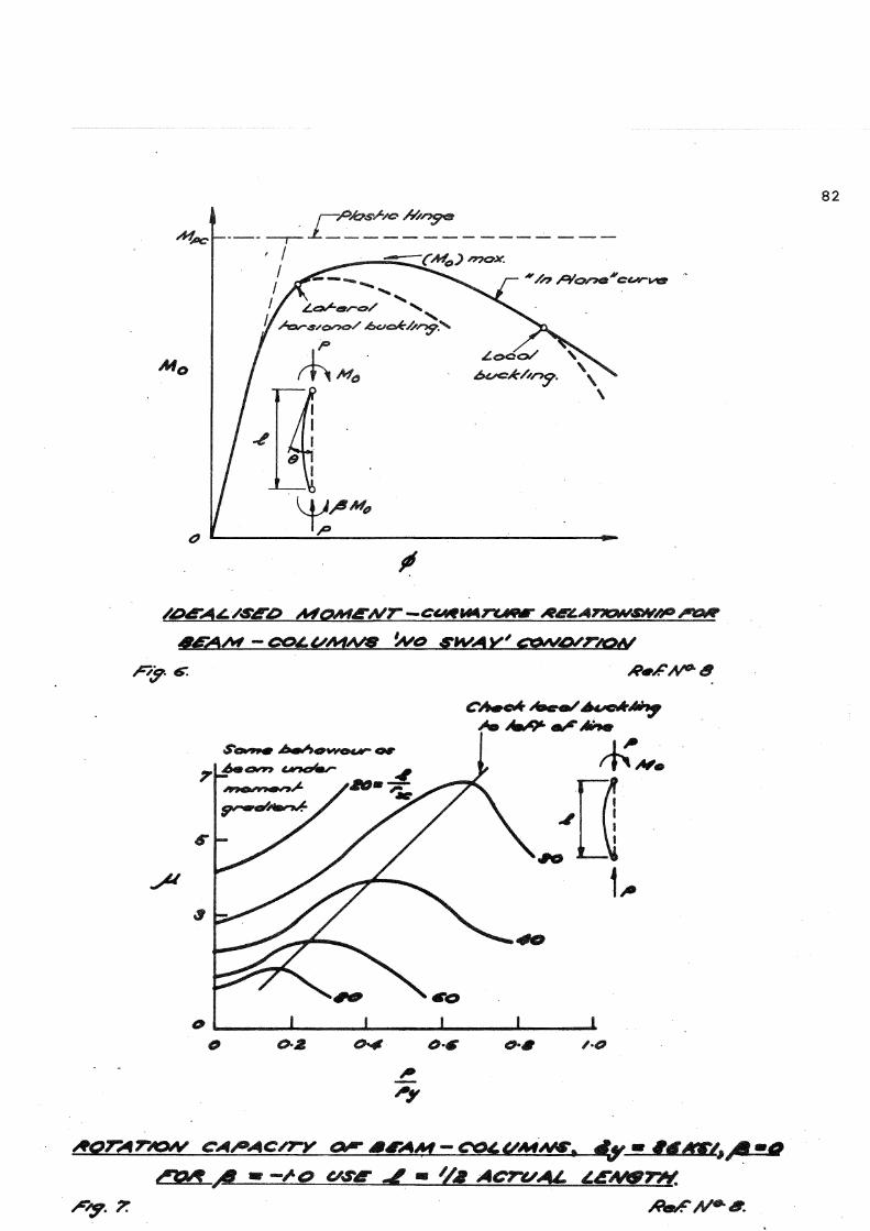
The moment-curvature relationship for beam-columns are similar to those for beams under uniform moment except for the effect of the axial load which tends to prevent the full plastic moment being reached. An idealised moment-curvature relationship is shown in Fig. 6.
A good estimate of the reduced plastic moment for universal columns bent about the strong axis is:
Mpc = 1.18 Mp ( 1 - %>y) | >, 0.15 *1
Mp = ay S - plastic moment of the section without axial load.
Py = A ay - the full plastic load. The reduction in moment capacity is due to the effect of 1 secondary' moments.
1. Due to the axial load x deflection at the centre of the column.
2. Reduction in flexural stiffness due to yielding.
In addition, just as in beams, 1 out of plane 1
effects such as lateral-torsional and local buckling tend also to reduce the moment capacity of beam-columns. This effect is also shown on Fig. 6.
Criteria to prevent lateral-torsional and local buckling are:
1. Local Buckling
Flange width/thickness and web depth/thickness ratios should be in accordance with the criteria for beams given previously.
2. Lateral-Torsionai Buckling
36 KSI 50 KSI 1) Single end moment or ^, ^ - ^
double curvature y 2) Double end moments , , 3 Q 2 P
single curvature / y
Theoretical curves showing the relationship of axial load ratio, slenderness ratio and section

75 curvature ductility factor for moment applied to one end of the column have been produced
(8) . These are shown in Fig. 7. They apply to universal column sections bent about their strong axis with a yield stress of 36 KSI for the 'sway prevented' condition.
Two methods of designing beam-columns in plastically designed frames and including P-A effects are given by Driscoll(13). One method is based upon the use of assumed drift which is then corrected as necessary and the other . treats the column as a restrained column using the technique of 'Subassemblages 1.
Currently columns in frames are designed to remain elastic and for this criteria the sum of the stresses in the columns should not exceed the yield stress of the material.
Where fworking stress' column design methods are using based upon normal interaction formulae, the effective length of columns should be determined from a clear column height using a co-efficient greater than 1.0.
A suitable alignment chart for determining effective lengths under 11 side sway not prevented" conditions is given in the AISC Specification Commentary(14) #
While it has been shown that this chart is conservative for columns with low slenderness ratios (the type normally found in buildings to resist earthquakes) as the elastic modulus and not the tangent modulus as used in the derivation, it is considered that this approach is justified.
Where welded built up columns are used, a conservative approach to axial loads should be adopted because of the high level of residual stress. For small to medium sized welded section where the heat input due to welding is high in comparison to steel area equivalent rolled sections are usually stronger. Under certain circumstances, however, heavy welded sections using gas cut plates may show the opposite relationship.
Column axial loads should be checked against the total shear strength of the members framing into the column. Current thinking is that columns and particularly corner columns should be designed for concurrent seismic loads along the main axes of the section.
A useful review of steel column behaviour under biaxial bending has been presented by Chen and Santathadapornd 5).
4.3 Connections
4.3.1 General
Connections require particularly careful attention to ensure that full advantage is taken of the energy absorbing capacity of the members joined, and to ensure full continuity of the structure and moment redistribution-. The design should be such that failure occurs first in the members joined rather than in the connection.
Connection must therefore have the following requirements:
1. Have a strength at least equal to the member
joined. This should include moment shear and axial load.
2. Have an energy absorbing capacity at least equal to the member joined.
Additional requirements for connections are:
1. Joints should be as simple as possible and practical to fabricate.
2. They should allow easy erection and quick release of expensive plant.
3. They should suit the erection sequence and not cause delays.
4. They should not be unduly sensitive to fabrication and erection tolerances so that excessive effort or extremely high workmanship is required.
5. They should be reasonably independent of climatic conditions if at all possible.
6. They must permit adequate access for erection and inspection.
7. They should be designed on a conservative basis.
Types of connection which are used in practice are:
1. Butt welded. 2. Fillet welded. 3. Fully bolted or rivetted. 4. A combination of any of the above.
Fully bolted or rivetted joints have been used in the past but the massive connections required to develop the moment capacity of the joined members as well as cost has tended against their continued use. Functional requirements, e.g. storey height restrictions also may preclude their use.
Generally, the most satisfactory way of meeting the above criteria is by welding or a combination of welding and bolting.
4.3.2 Tests on Connections
Tests on three basic types of beam-column connections subjected to cyclic reversed loading have been reported by Popov and Pinkney' 1 6'. These tests were carried out in a similar manner to the beam tests discussed earlier. The three basic types of joints tested were:
(i) A butt-welded joint in which the beam was welded direct to the column.
(ii) A fillet-welded joint with flange plates. (iii) A high-strength bolted joint with flange
plates. In all cases the columns were assumed to remain elastic. The three types of joints are shown in Fig. 8. Failure was by fracture through the flanges or moment plates. The number of cycles to failure for the various types of joints was as follows:
A. For the Flange Connection
1. Butt welded joints 22.1/2 to 120 2. Fillet welded joints 18 to 44 3. Bolted joints 9.1/2 to 65.1/2
B. For the Web Connection
1. Butt welded joints 37 - 51.1/2 (Disregarding joints which failed due to weld defects)

76 2. Fillet welded joints 30 - 46.1/2
Using- accumulated energy as the criterion of satisfactory performance Popov found that the butt-welded connections were superior to the other types tested. This conclusion applies to both mild steel and the high-yield steel connections.
The hysteresis loops for bolted joints were affected by slippage at the faying surface, This reduced the area of the loops considerably. The stages of bolt action which could be identified were:
1. Static friction resistance. 2. Active slip. 3. Bearing on the bolts.
In specimens drilled with smaller than normal oversize holes the slip was less and the hysteresis loops approached the more typical shapes obtained for welded joints.
Further tests have been carried out by Popov and Stephen(17) on full size joints. Beams were 18" and 24" deep universal beams with fully welded and flange welded-web bolted joints. These tests highlighted the large increase due to strain hardening in the maximum moment compared to the plastic moment even when the actual yield stress of the material was used in deriving the latter. The increase was up to 69%. In one test the flanges only were welded to the column and they alone transmitted moment and shear. From the test result it would seem that the concept that flanges transfer moment and webs transfer shear may not be correct at the connection.
However, the SEAOC Steel Subcommittee ^ 1 8^ were not impressed by this series of tests and voted against the use of "web bolted, flange welded girder connection in steel ductile moment resisting frames" at this time. The reasons given for rejection were "the inconsistencies in the data" such as:
1. Variation in the type of failure. 2. Variation in the joint stiffnesses. 3. Stronger bolted connections developed less
moment than weaker ones. 4. Connections without web attachment also
developed the full plastic capacity of the joined beam.
More conclusive test data is required.
4.3.3 Design of Beam Column Joints
In the design of connections consideration must be given to factors which may increase the nominal plastic moment value Mp of the beam.
1. Yield Strength
Structural steel is normally supplied to a specification with a minimum yield stress. In fact the average yield stress is higher than the minimum by the following factors.
36 KSI 1.15 50 KSI 1.10
These factors should be used when determining the plastic moment Mp. 2. Strain Hardening
In section 4 it was seen that under moment
gradient a universal beam section is subjected to strain hardening. The effect is to increase the maximum moment value to approximately 1.4 Mp.
3. Butt Welded"Joints
Suitable design methods for butt welded connections in steel moment resisting space frames are given in ASCE Manual 41 ' 1 C ' .
4. Fillet Welded Joints
The AISC Specification 196? Part 2 ( 5 )
recommends the use of butt >yeids rather than fillet welds for jointing plastically designed members but their use is not mandatory.
Fillet welded joints of various types have been tested under monotonic loading and shown to be capable of developing the full plastic moment of the member joined.
The Popov tests with flange connecting plates are the only cyclic loading tests that have been carried out on such joints as far as is known.
To avoid biaxial stress conditions the fillet weld should not be continuous along the full length of the flange plate.
Some information on the ultimate strength of fillet welds has been given by Higgins & Preeced9) . The ASCE Manual No, 4lClO) specified plastic design stresses to be used.
5. Bolted Joints
Tests on beam splices as well as beam column connections such as those discussed in Section 4 above have shown that bolted joints can develop the full plastic moment of the connected members.
For the range of steels recommended for plastic design and for use in earthquake resisting structures the reduction in flange area of flexural members may be neglected provided the nett section has sufficient strength to 'develop 1 gross section yielding.
Based upon A-572 steel where £x = 0.85
the nett to gross area should satisfy the relationship.
A nett A aross 5au
Design methods for bolted connections are given in ASCE Manual 4 1 f i 0 ) ,
Another type of bolted joint which has not been subjected to cyclic loading but which has been found to be satisfactory•for plastically designed frames(6) is shown in Fig. 9. The joint consists of end plates either fillet or butt welded to the ends of the beams, high strength bolted to the columns. Tolerances may be allowed for by the introduction of shims directly under the bolts. The high strength bolts are subject to "prizing" effects.
Surtees and Mann have developed design methods for the joint based upon the original work by Sherbourne and recent tests. The design

77
Unfortunately non-destructive testing methods are unable to give a sufficiently accurate identification of the lamellae to determine the susceptibility to tearing.
Under stress at right angles to the thickness, the non-metallic inclusions separate from the matrix and join up by tearing of the matrix between. This gives rise to the characteristic stepped failure pattern so typical of lamellar tearing.
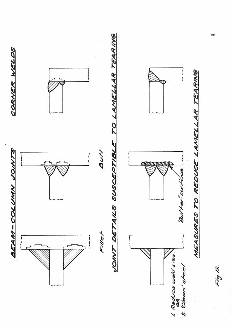
Methods of avoiding lamellar tearing include: (See Fig. 12)
1. The use of 'clean 1 plate. 2. 1 Buttering 1 the plates in the area of the
joint with weld metal. This involves replacing the original metal with 'clean* weld metal (which has no flow structure) to the depth of the heat affected zone.
3. Within limits altering the preparation for .welding.
4. The use of bolted connections.
The development in metallurgical processes discussed briefly in Section 3 Materials should assist in overcoming the problem.
6. BEHAVIOUR OF FULL SIZE STEEL FRAMES
1. Shear deformation in Column , n Web D U
2. End Plate Flexure 18 3. Column Flange Flexure 17 4. Tensile Strain in Column Web 6 5. Compressive strain in column Web
and Stiffener 9
Probably the best known early dynamic * tests on a full sized steel frame building are those reported by Nielsen. The tests were carried out on a nine storey building at various stages of construction to determine dynamic response under man excitation and steady state tests.
It is believed that a similar magnitude of shear deformation would occur in a fully welded connection.
The panel zone has been discussed by Bertero who suggested a programme of investigation into the inelastic behaviour of panel zones.
Under the action of the moments in the two beams framing into the column large shears occur in the column web as shown in the free body diagram Fig. 11.
Adopting Von Mises yield criterion the required web thickness is found as shown in Fig. 11.
This analysis assumes that buckling of the panel will not occur. This is possibly a safe assumption where four beams frame into the joint at right angles.
5. LAMELLAR TEARING
The anisotropic properties of steel give rise to problems of lamellar tearing at joints under conditions of stress induced by welding in the thickness direction of the plate or section. Particularly susceptible are beam-column joints where beams are welded to the, relatively thick flanges of the column section under conditions of high restraint. Cooper(21) has given details of the problem and measures taken to overcome it.
During the rolling of the steel plate or section non-metallic inclusions such as manganese silicates and sulphides are rolled out into layers in the direction of rolling imparting a 'flow' structure to the steel.
From tests such as this and a review of most of '•the available literature on damping Newmark and Hall recommend the following values of damping for various types of steel frames.
Stress Level Type & Condition off Structure
Percentage of Critical Damping
No joint slip 0.5 - 1 a. Welded 2 b. Bolted,
rivetted 5 - 7
a. Welded 5 b. Bolted,
rivetted 10 - 15
a. Welded 7 10 b. Bolted,
rivetted 20
1-4% yield point 2 . < % yield point
3.^ Yield point
4.̂ > Yield point Permanent Straii^ Yield Strain
Of great importance have been the tests carried out at Lehigh University on single bay one and three storey frames under constant gravity load and repeated and reversed horizontal loads. Results of the tests have been published by Carpenter and Lu. The frames consisted of 8" x 8" x 401b UC and 10" x 5%" x 291b UB sections with a span of 15 ft and a 10 ft storey height. The frames were subjected to increasing lateral displacement, 60 cycles in the case of the single storey frame and 54 cycles for the three storey. Maximum deflections from the initial position were 5.2 inches for the single storey and 13.5 inches for the three storey.
method is given in Fig. 9.
4.4 Deformation of the Panel Zone;
The importance of the panel zone of the column at a beam column junction is now realised by designers.
Little is known .of the panel zone's strength, stiffness and ductility under cyclic loading despite the fact that the panel zone plays an important part in the total inelastic deflection of a frame. The deformation of the panel zone is shown in an idealised manner in Fig. 10.
As discussed earlier the joint may contribute some 25 - 3 5% of the total interstorey deflection at mid height of a 40 storey building. Of this amount a large portion will obviously be from panel zone distortion.
Surtees and Mann ̂ 2 0^ in tests on high strength bolted end plate beam-column connections found the following contribution to rotation from the components of a joint at a loading of 60% of the plastic moment.
% Contribution to Total Rotation

78 The maximum load capacity was 40% greater
than the maximum monotonically applied lateral load predicted by second order elastic plastic analysis• As a result of the tests Carpenter and Lu have drawn the following tentative conclusions :
1. The hysteresis loops are very stable even for deformations greater than those corresponding to the maximum lateral load.
2. A considerable increase in lateral load carrying capacity over that expected from a monotonic analysis is possible.
3. Strain-hardening plays an important role in the behaviour of the frames for displacements greater than those at the maximum loads.
4. The presence of the residual P-A moments has significant effects on frame behaviours and must be included in developing a rational method of analysis., for repeatedly loaded frames.
5. The shape of the hysteresis loops is affected by the reduction of frame stiffness under reversed loading due to spread of yielding in the plastic hinge locations and the Bauschinger effect in the material.
7. CONCLUSIONS
Structural steel has proved to be a material with good behaviour characteristics for use in buildings subjected to seismic loading.
Providing the design includes measures to prevent local buckling and lateral-torsional instability, the beam and beam-column components of the frame are capable of reaching their full plastic moment well into the inelastic ranges. The absence of such measures is likely to cause premature unloading before the full inelastic potential is reached. In addition connections must be designed to match the potential of the members being joined.
Under these circumstances steel will perform well with highly reproducible hysteresis loops under cyclic loading. Such hysteresis loops give a reliable measure of the energy absorption and dissipation of the frame.
9. Lukey A.F. and Adams P.F. (1969), "Rotation Capacity of Beams Under Moment Gradient", Journal of the Structural Division ASCE 95 No. ST6 (June).
10. (1971) "Plastic Design in Steel A Guide and Commentary", ASCE Manual No. 41 (Second Edition).
11. Bertero V.V. and Popov E.P. (1965), "Effect of Large Alternating Strains on Steel Beams", Journal of the Structural Division ASCE 91 No. ST1 (February). -
12. Newmark N.M. and Rosenblueth E. (1971), "Fundamentals of Earthquake Engineering".
13. Driscoll G.C. et al (1965) "Plastic Design of Multi-Story Frame", Conference presented by LeHigh University.
14. (1969) Commentary on the Specification for the Design Fabrication and Erection of Structural Steel for Buildings AISC . (February).
15. Chen W.F. and Santathadaporn S. (1968) "Review of Column Behaviour Under Biaxial Loading", Journal of the Structural division ASCE ST 94.12 (December).
16. Popov and Pinkney R.B. (1967) "Behaviour of Steel Building Connections Subjected to Repeated Strain Reversal" SESM 67 - 30 University of California (December).
17. Popov E'.P. and Stephen R.M. ,(1972) , "Cyclic Loading of Full Size Steel Connections" AISI Steel Research for Construction Bulletin No. 21 (February).
18. (1971) Building Code Steel Subcommittee SEAOC Bulletin (November).
19. Higgins T.R. and Preece F.R. (1969), "Proposed Working Stresses for Fillet Welds in Building Construction", AISC Engineering Journal 6.1 (January).
20. Surtees J.O. and Mann A.P. (1970), "End Plate Connections in Plastically Resigned Structures", Conference on Joints in Structures Institution of Structural Engineers/University of Sheffield (July).
21. Cooper G. (1968), "Use of Steel to BS 968: 1962 in the All-Welded Frame of a 19 Storey Building" N.Z. Engineering 23*1 (January).
8. REFERENCES
1. Galloway J.D. et al (1907) San Francisco Earthquake "Report of Committee on Fire and Earthquake Damage to Buildings", Appendix B ASCE Transactions LIX.
2. Berg G.V. and Stratta J.L. (1964) "Anchorage and the Alaska Earthquake of March 21, 1964", AISI.
3. Hanson R.D. and Degenkolb H.J. (1969), "The Venezuela Earthquake July 29, 1967", AISI.
4. (1971) Task Group 5, Cilumn Research Council, "Classification of Steels for Structures", AISC Engineering Journal 8•3 (July).
5. (1969) Specification for the Design, Fabrication and Erection of Structural Steel for Buildings AISC (February).
6. (1971) "Fully Rigid Multi-Storey Welded Steel Frames", Joint Committee 1s Second Report. The Institution of Structural Engineers The Welding Institute (May).
7. Teal E.J. (1968), "Structural Steel Seismic Frames - Drift and Ductility Requirements", Proceedings 37th Annual Convention SEAOC.
8. Galambos T.V. (1968), "Deformation and Energy Absorption Capacity of Steel Structures in the Inelastic Range", AISI Steel Research for Construction Bulletin No. 8 (March).

t 0
1
V i
V V
i 1 £csc/r/v?y

8 0
m Mp
1-4
1-2
1-0
0*8
0 «6 L
L O C A L BUCKLING A - 2 (A36)
b / t = 16*3
LOCAL BUCKLING
A _ 2 )
-|„2 ) s f o m e n t Gradient
C = Uniform Moment ± 4 6 10 12
FIG. 3
14
OAeT/<° j&Gsosr? csncrfms* M O / w * / ? / g>s~&c//*es?£ OAS A/o Ad>c£3?/ /c*/-&sx?/ &<scAr/ss-^.
S&O&S/Ai^ AfOA*£Wr*~ C£S&W<A7mtS&£r /t£X.ATTOA/SW/^
FAILURE 7 0 0 f
6 0 0
500
400
300
200
00
i
com / s"
ROLLING FRAIH
M ^ p - . ^ ™ ^ . ^
V
0.5 1.0 1.5 2.0
C O N T R O L L I N G C Y C L I C S T R A 1 N ; ( % ) , ( ± )
2.5
FIG.5 NO. OF CYCLES REQUIRED TO A T T A I N FRACTURE AS
A FUNCTION OF THE CONTROLLING CYCLIC STRAIN.
82
//7 /^/ar^ GC#- m-r
a-js o>* as &•#

83
5 E C K O N A . " AK
' / a , * t > - ^ * B A R .
S* * ^v* B O S S e AC ti &|
• E R t C t l O N C U I f * & BACWNG L.
K- S-iO^ 1 1 - —
Type Pi W E U D E O & t » ^ x t v t c o L u m J N U O I M T .
F t G U A C I •
+V£ CRKLllCMr, ,l | 0 |
S E C T IOfN /\ S E C T I O N e>~e»
4
. IE
30 ' ' s N ^ BACKING e ' W * ^ B O S S E A C H S | D C r 1
50 ERECTION C U P & EVKCKir -JG L.
" T V P e F 2 W E L D E D B » E / » t l v * C O L U M N J O I N T
nk
S E C T tors /\ - /x
H.S. ^ O L T S
F I L L E R
TT1 ^ N C U G W E L D E D T O C O L U M N
T V P E BOLTGD B.£A.tv\ COLUMN JOINT