Embed Size (px)
Citation preview
Steel deck design
Advance Design allows creating an new type of steel slab/deck - Non-composite steel slab. The non-composite slabs may be used as floors in lightweight structures or as a form for reinforced concrete slabs.
Steel decks
Steel decks, or Non-composite steel slabs, are created directly in the graphic area. The position of the slab is specified by entering the coordinates on the command line or by snapping to other objects.
Accessing the command Menu: Select Generate > Structure > Plate.
Linear & Plate creation toolbar: click .
Either method activates the drawing tool and the property window. The plate type can be selected from the General > Type drop-down list in the Properties window.
After selecting non-composite steel slab, press <Enter> to validate it.
Creating a steel deck / non-composite steel slab The procedures for drawing a non-composite steel slab are similar to the ones for other slab-type elements. See How to create simple planar elements in the Simple planar elements topic.
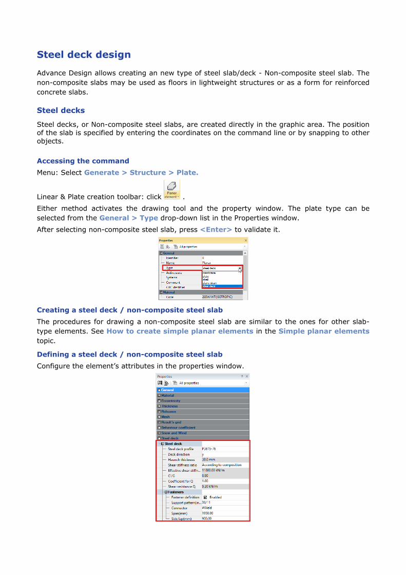
Defining a steel deck / non-composite steel slab Configure the element’s attributes in the properties window.
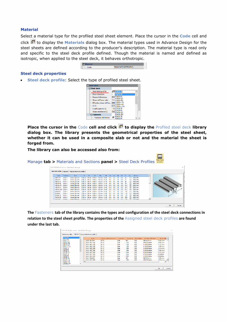
Material Select a material type for the profiled steel sheet element. Place the cursor in the Code cell and click to display the Materials dialog box. The material types used in Advance Design for the steel sheets are defined according to the producer’s description. The material type is read only and specific to the steel deck profile defined. Though the material is named and defined as isotropic, when applied to the steel deck, it behaves orthotropic.
Steel deck properties • Steel deck profile: Select the type of profiled steel sheet.
Place the cursor in the Code cell and click to display the Profiled steel deck library dialog box. The library presents the geometrical properties of the steel sheet, whether it can be used in a composite slab or not and the material the sheet is forged from. The library can also be accessed also from:
Manage tab > Materials and Sections panel > Steel Deck Profiles
The Fasteners tab of the library contains the types and configuration of the steel deck connections in relation to the steel sheet profile. The properties of the Assigned steel deck profiles are found under the last tab.
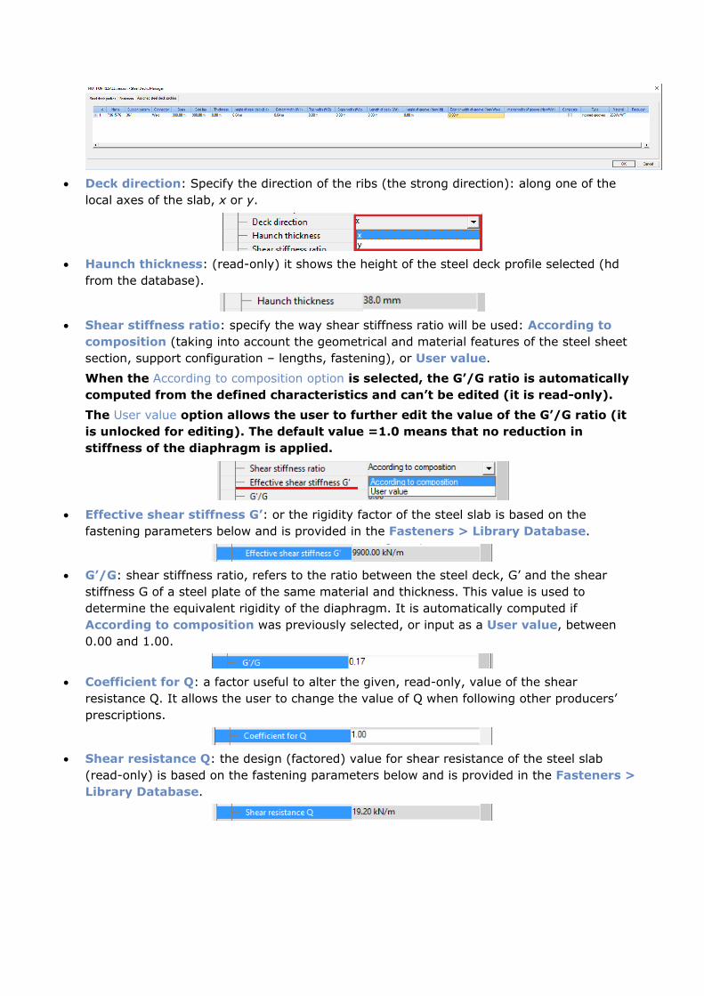
• Deck direction: Specify the direction of the ribs (the strong direction): along one of the
local axes of the slab, x or y.
• Haunch thickness: (read-only) it shows the height of the steel deck profile selected (hd
from the database).
• Shear stiffness ratio: specify the way shear stiffness ratio will be used: According to
composition (taking into account the geometrical and material features of the steel sheet section, support configuration – lengths, fastening), or User value.
When the According to composition option is selected, the G’/G ratio is automatically computed from the defined characteristics and can’t be edited (it is read-only). The User value option allows the user to further edit the value of the G’/G ratio (it is unlocked for editing). The default value =1.0 means that no reduction in stiffness of the diaphragm is applied.
• Effective shear stiffness G’: or the rigidity factor of the steel slab is based on the
fastening parameters below and is provided in the Fasteners > Library Database.
• G’/G: shear stiffness ratio, refers to the ratio between the steel deck, G’ and the shear
stiffness G of a steel plate of the same material and thickness. This value is used to determine the equivalent rigidity of the diaphragm. It is automatically computed if According to composition was previously selected, or input as a User value, between 0.00 and 1.00.
• Coefficient for Q: a factor useful to alter the given, read-only, value of the shear
resistance Q. It allows the user to change the value of Q when following other producers’ prescriptions.
• Shear resistance Q: the design (factored) value for shear resistance of the steel slab
(read-only) is based on the fastening parameters below and is provided in the Fasteners > Library Database.
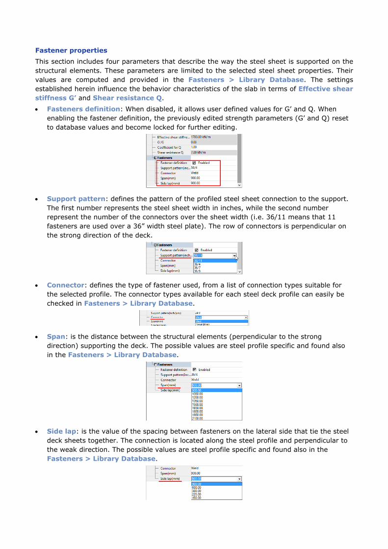
Fastener properties This section includes four parameters that describe the way the steel sheet is supported on the structural elements. These parameters are limited to the selected steel sheet properties. Their values are computed and provided in the Fasteners > Library Database. The settings established herein influence the behavior characteristics of the slab in terms of Effective shear stiffness G’ and Shear resistance Q.
• Fasteners definition: When disabled, it allows user defined values for G’ and Q. When enabling the fastener definition, the previously edited strength parameters (G’ and Q) reset to database values and become locked for further editing.
• Support pattern: defines the pattern of the profiled steel sheet connection to the support. The first number represents the steel sheet width in inches, while the second number represent the number of the connectors over the sheet width (i.e. 36/11 means that 11 fasteners are used over a 36” width steel plate). The row of connectors is perpendicular on the strong direction of the deck.
• Connector: defines the type of fastener used, from a list of connection types suitable for the selected profile. The connector types available for each steel deck profile can easily be checked in Fasteners > Library Database.
• Span: is the distance between the structural elements (perpendicular to the strong direction) supporting the deck. The possible values are steel profile specific and found also in the Fasteners > Library Database.
• Side lap: is the value of the spacing between fasteners on the lateral side that tie the steel deck sheets together. The connection is located along the steel profile and perpendicular to the weak direction. The possible values are steel profile specific and found also in the Fasteners > Library Database.
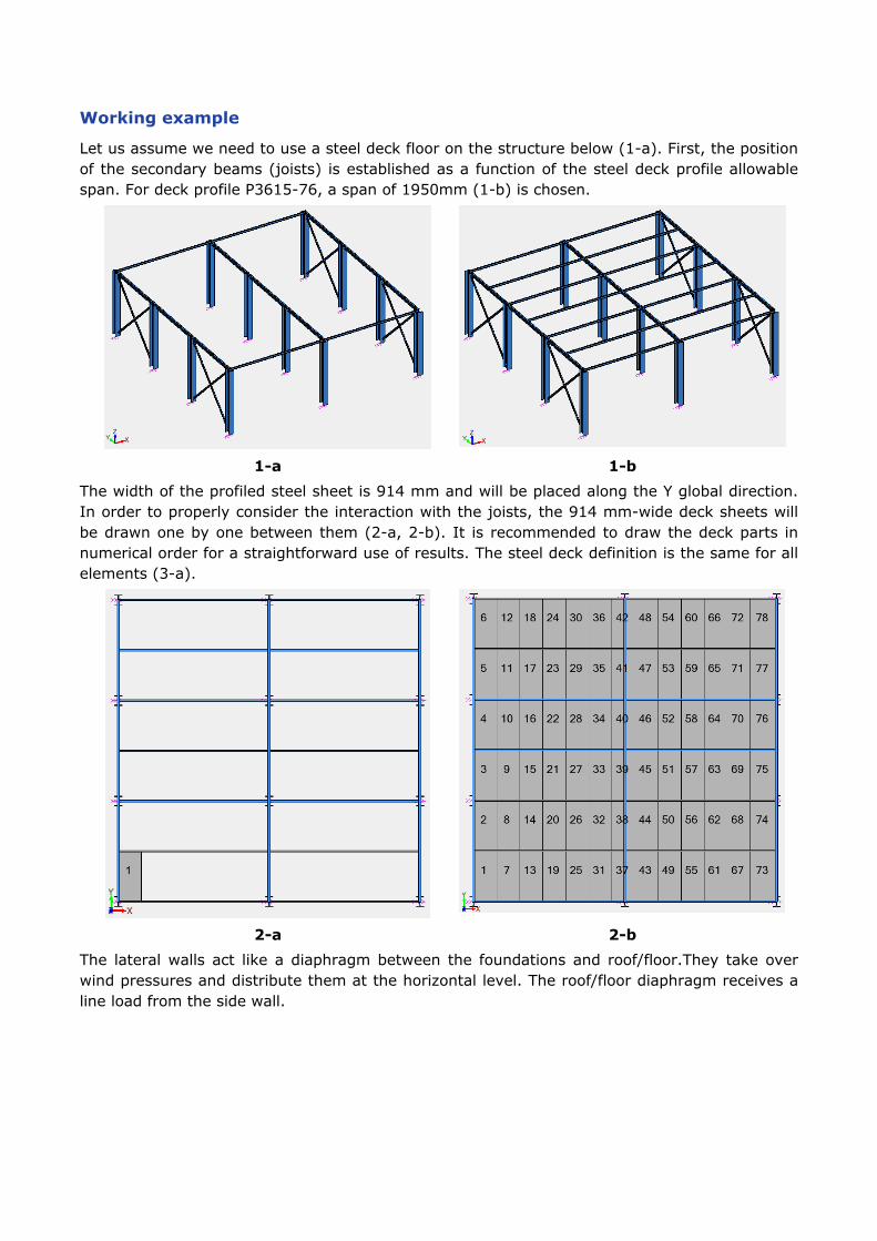
Working example
Let us assume we need to use a steel deck floor on the structure below (1-a). First, the position of the secondary beams (joists) is established as a function of the steel deck profile allowable span. For deck profile P3615-76, a span of 1950mm (1-b) is chosen.
1-a 1-b
The width of the profiled steel sheet is 914 mm and will be placed along the Y global direction. In order to properly consider the interaction with the joists, the 914 mm-wide deck sheets will be drawn one by one between them (2-a, 2-b). It is recommended to draw the deck parts in numerical order for a straightforward use of results. The steel deck definition is the same for all elements (3-a).
2-a 2-b The lateral walls act like a diaphragm between the foundations and roof/floor.They take over wind pressures and distribute them at the horizontal level. The roof/floor diaphragm receives a line load from the side wall.
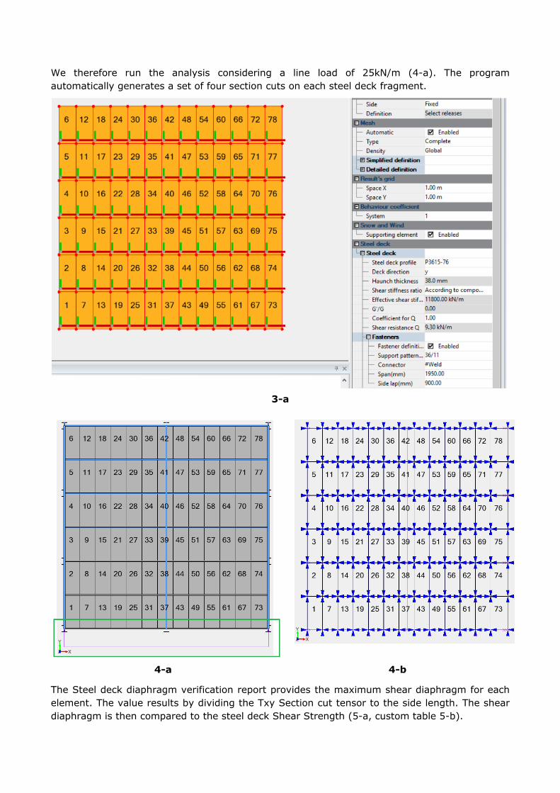
We therefore run the analysis considering a line load of 25kN/m (4-a). The program automatically generates a set of four section cuts on each steel deck fragment.
3-a
4-a 4-b
The Steel deck diaphragm verification report provides the maximum shear diaphragm for each element. The value results by dividing the Txy Section cut tensor to the side length. The shear diaphragm is then compared to the steel deck Shear Strength (5-a, custom table 5-b).
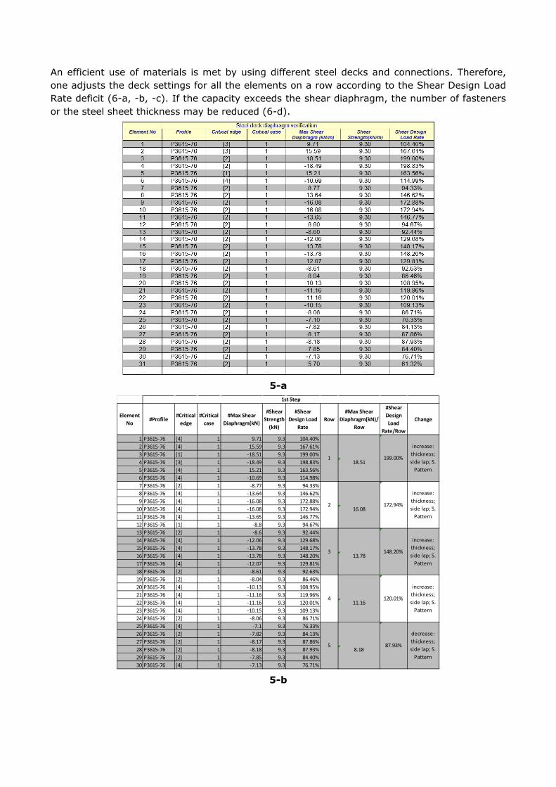
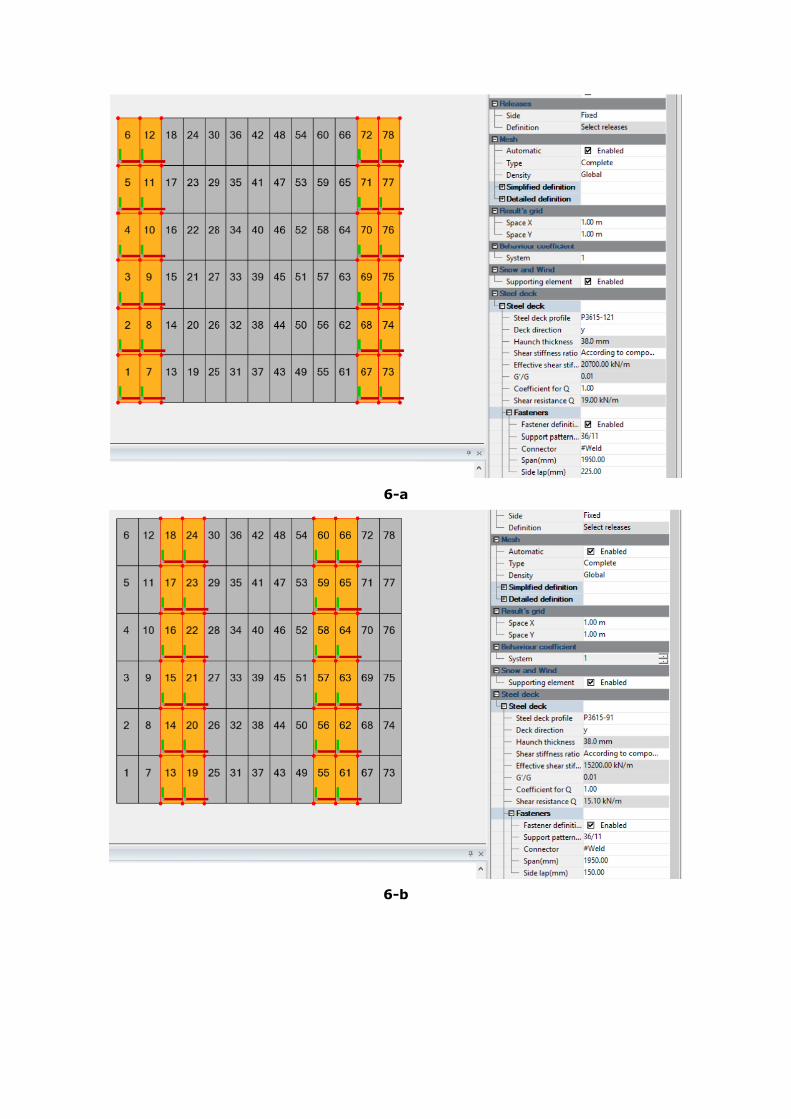
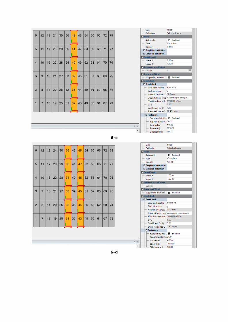
An efficient use of materials is met by using different steel decks and connections. Therefore, one adjusts the deck settings for all the elements on a row according to the Shear Design Load Rate deficit (6-a, -b, -c). If the capacity exceeds the shear diaphragm, the number of fasteners or the steel sheet thickness may be reduced (6-d).
5-a
Element No
#Profile#Critical
edge#Critical
case#Max Shear
Diaphragm(kN)
#Shear Strength
(kN)
#Shear Design Load
RateRow
#Max Shear Diaphragm(kN)/
Row
#Shear Design Load
Rate/Row
Change
1 P3615-76 [4] 1 9.71 9.3 104.40%2 P3615-76 [4] 1 15.59 9.3 167.61%3 P3615-76 [1] 1 -18.51 9.3 199.00%4 P3615-76 [3] 1 -18.49 9.3 198.83% 18.515 P3615-76 [4] 1 15.21 9.3 163.56%6 P3615-76 [4] 1 -10.69 9.3 114.98%7 P3615-76 [2] 1 -8.77 9.3 94.33%8 P3615-76 [4] 1 -13.64 9.3 146.62%9 P3615-76 [4] 1 -16.08 9.3 172.88%
10 P3615-76 [4] 1 -16.08 9.3 172.94% 16.0811 P3615-76 [4] 1 -13.65 9.3 146.77%12 P3615-76 [1] 1 -8.8 9.3 94.67%13 P3615-76 [2] 1 -8.6 9.3 92.44%14 P3615-76 [4] 1 -12.06 9.3 129.68%15 P3615-76 [4] 1 -13.78 9.3 148.17%16 P3615-76 [4] 1 -13.78 9.3 148.20% 13.7817 P3615-76 [4] 1 -12.07 9.3 129.81%18 P3615-76 [2] 1 -8.61 9.3 92.63%19 P3615-76 [2] 1 -8.04 9.3 86.46%20 P3615-76 [4] 1 -10.13 9.3 108.95%21 P3615-76 [4] 1 -11.16 9.3 119.96%22 P3615-76 [4] 1 -11.16 9.3 120.01% 11.1623 P3615-76 [4] 1 -10.15 9.3 109.13%24 P3615-76 [2] 1 -8.06 9.3 86.71%25 P3615-76 [4] 1 -7.1 9.3 76.33%26 P3615-76 [2] 1 -7.82 9.3 84.13%27 P3615-76 [2] 1 -8.17 9.3 87.86%28 P3615-76 [2] 1 -8.18 9.3 87.93% 8.1829 P3615-76 [2] 1 -7.85 9.3 84.40%30 P3615-76 [4] 1 -7.13 9.3 76.71%
1st Step
120.01%
increase: thickness; side lap; S.
Pattern
87.93%
decrease: thickness; side lap; S.
Pattern
1
2
3
4
5
199.00%
increase: thickness; side lap; S.
Pattern
172.94%
increase: thickness; side lap; S.
Pattern
148.20%
increase: thickness; side lap; S.
Pattern
5-b
6-a
6-b
6-c
6-d
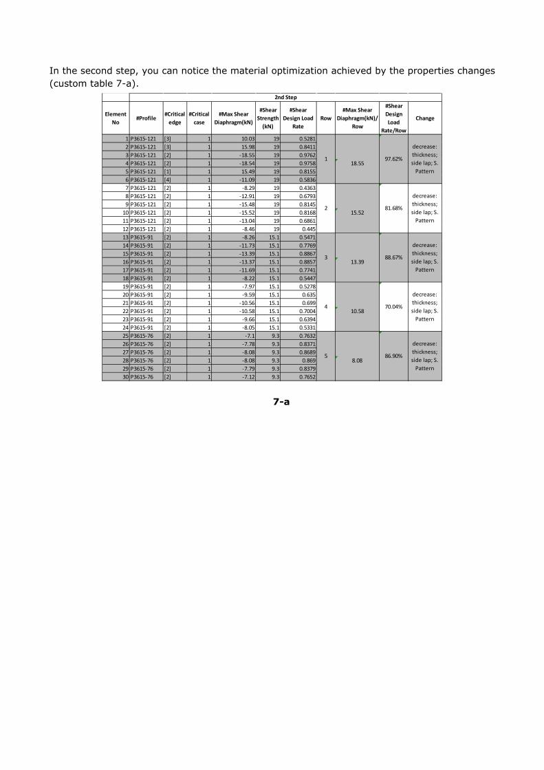
In the second step, you can notice the material optimization achieved by the properties changes (custom table 7-a).
Element No
#Profile#Critical
edge#Critical
case#Max Shear
Diaphragm(kN)
#Shear Strength
(kN)
#Shear Design Load
RateRow
#Max Shear Diaphragm(kN)/
Row
#Shear Design Load
Rate/Row
Change
1 P3615-121 [3] 1 10.03 19 0.52812 P3615-121 [3] 1 15.98 19 0.84113 P3615-121 [2] 1 -18.55 19 0.97624 P3615-121 [2] 1 -18.54 19 0.9758 18.555 P3615-121 [1] 1 15.49 19 0.81556 P3615-121 [4] 1 -11.09 19 0.58367 P3615-121 [2] 1 -8.29 19 0.43638 P3615-121 [2] 1 -12.91 19 0.67939 P3615-121 [2] 1 -15.48 19 0.8145
10 P3615-121 [2] 1 -15.52 19 0.8168 15.5211 P3615-121 [2] 1 -13.04 19 0.686112 P3615-121 [2] 1 -8.46 19 0.44513 P3615-91 [2] 1 -8.26 15.1 0.547114 P3615-91 [2] 1 -11.73 15.1 0.776915 P3615-91 [2] 1 -13.39 15.1 0.886716 P3615-91 [2] 1 -13.37 15.1 0.8857 13.3917 P3615-91 [2] 1 -11.69 15.1 0.774118 P3615-91 [2] 1 -8.22 15.1 0.544719 P3615-91 [2] 1 -7.97 15.1 0.527820 P3615-91 [2] 1 -9.59 15.1 0.63521 P3615-91 [2] 1 -10.56 15.1 0.69922 P3615-91 [2] 1 -10.58 15.1 0.7004 10.5823 P3615-91 [2] 1 -9.66 15.1 0.639424 P3615-91 [2] 1 -8.05 15.1 0.533125 P3615-76 [2] 1 -7.1 9.3 0.763226 P3615-76 [2] 1 -7.78 9.3 0.837127 P3615-76 [2] 1 -8.08 9.3 0.868928 P3615-76 [2] 1 -8.08 9.3 0.869 8.0829 P3615-76 [2] 1 -7.79 9.3 0.837930 P3615-76 [2] 1 -7.12 9.3 0.7652
2nd Step
decrease: thickness; side lap; S.
Pattern
4 70.04%
decrease: thickness; side lap; S.
Pattern
5 86.90%
decrease: thickness; side lap; S.
Pattern
1 97.62%
decrease: thickness; side lap; S.
Pattern
2 81.68%
decrease: thickness; side lap; S.
Pattern
3 88.67%
7-a