Embed Size (px)
Citation preview
©Thermoflow, Inc. 2018 – Webinar on Modifying Steam Turbine Models in THERMOFLEX , February 2018 - Norm Decker
Steam Turbine Series Part 2:Modifying a Steam Turbine Model in
THERMOFLEX
Using Steam Turbine Assembly menu to make model match known
specifications

©Thermoflow, Inc. 2018 – Webinar on Modifying Steam Turbine Models in THERMOFLEX , February 2018 - Norm Decker
Feature Awareness Webinar Series

©Thermoflow, Inc. 2018 – Webinar on Modifying Steam Turbine Models in THERMOFLEX , February 2018 - Norm Decker
Modify a Steam Turbine Model: Tasks
Match Inlet Conditions and other Flows
Match Pressures
Match
Enthalpies
Match Power
Iterate as needed

©Thermoflow, Inc. 2018 – Webinar on Modifying Steam Turbine Models in THERMOFLEX , February 2018 - Norm Decker
Isolate a Steam Turbine Model: Then & Now
CopyComponents
Build supporting Network
Select Components
Copy to Catalog
Place in Isolated Flowsheet,
Network Already in Place
©Thermoflow, Inc. 2018 – Webinar on Modifying Steam Turbine Models in THERMOFLEX , February 2018 - Norm Decker
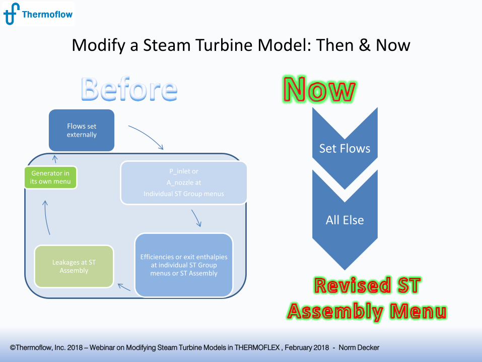
Flows set externally
P_inlet or
A_nozzle at
Individual ST Group menus
Efficiencies or exit enthalpies at individual ST Group menus or ST Assembly
Leakages at ST Assembly
Generator in its own menu
Modify a Steam Turbine Model: Then & Now
Set Flows
All Else

©Thermoflow, Inc. 2018 – Webinar on Modifying Steam Turbine Models in THERMOFLEX , February 2018 - Norm Decker
Background: Solar Rankine Cycle of Part I
IPT LPT ST
CND
Already-built Pieces
New Piece
C H
HPT
S R
E
HP2 HP1 DA LP3 LP2 LP1
1800
475 100
300
175
3812

©Thermoflow, Inc. 2018 – Webinar on Modifying Steam Turbine Models in THERMOFLEX , February 2018 - Norm Decker
In Part I, we began with a Starter Model, representing a prospective system model …
Part I added a steam turbine and condenser to this model that was already in progress with known main steam supply and assumed FWH train

©Thermoflow, Inc. 2018 – Webinar on Modifying Steam Turbine Models in THERMOFLEX , February 2018 - Norm Decker
Using the ST Assembly Wizard, a new ST was added to that Starter Model. This is where we’ll pick up today
Resulting Model

©Thermoflow, Inc. 2018 – Webinar on Modifying Steam Turbine Models in THERMOFLEX , February 2018 - Norm Decker
A closer look at the turbine…

©Thermoflow, Inc. 2018 – Webinar on Modifying Steam Turbine Models in THERMOFLEX , February 2018 - Norm Decker
Responding to a request for a proposed turbine to fit these needs, a vendor responds with a heat balance of his own…
©Thermoflow, Inc. 2018 – Webinar on Modifying Steam Turbine Models in THERMOFLEX , February 2018 - Norm Decker
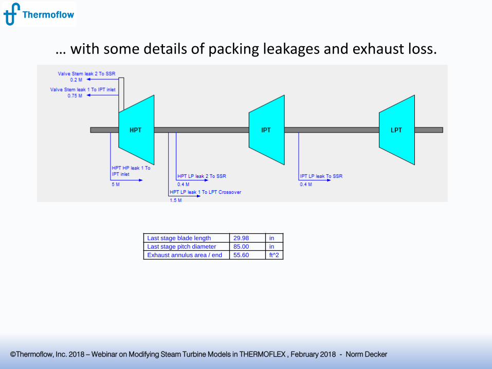
… with some details of packing leakages and exhaust loss.
Last stage blade length 29.98 in
Last stage pitch diameter 85.00 in
Exhaust annulus area / end 55.60 ft^2

©Thermoflow, Inc. 2018 – Webinar on Modifying Steam Turbine Models in THERMOFLEX , February 2018 - Norm Decker
This leaves you with the task of implementing the vendor’s design of the steam turbine, merging it with your developing model.
©Thermoflow, Inc. 2018 – Webinar on Modifying Steam Turbine Models in THERMOFLEX , February 2018 - Norm Decker
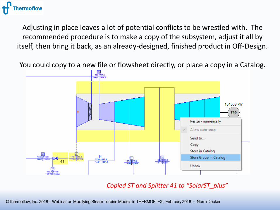
Adjusting in place leaves a lot of potential conflicts to be wrestled with. The recommended procedure is to make a copy of the subsystem, adjust it all by
itself, then bring it back, as an already-designed, finished product in Off-Design.
You could copy to a new file or flowsheet directly, or place a copy in a Catalog.
Copied ST and Splitter 41 to “SolarST_plus”
©Thermoflow, Inc. 2018 – Webinar on Modifying Steam Turbine Models in THERMOFLEX , February 2018 - Norm Decker
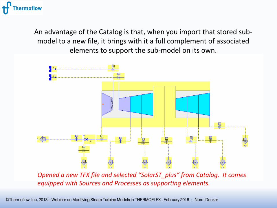
An advantage of the Catalog is that, when you import that stored sub-model to a new file, it brings with it a full complement of associated
elements to support the sub-model on its own.
Opened a new TFX file and selected “SolarST_plus” from Catalog. It comes equipped with Sources and Processes as supporting elements.
©Thermoflow, Inc. 2018 – Webinar on Modifying Steam Turbine Models in THERMOFLEX , February 2018 - Norm Decker
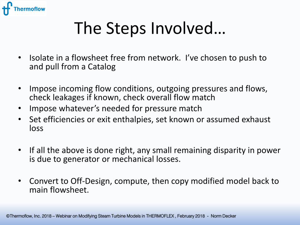
The Steps Involved…
• Isolate in a flowsheet free from network. I’ve chosen to push to and pull from a Catalog
• Impose incoming flow conditions, outgoing pressures and flows, check leakages if known, check overall flow match
• Impose whatever’s needed for pressure match• Set efficiencies or exit enthalpies, set known or assumed exhaust
loss
• If all the above is done right, any small remaining disparity in power is due to generator or mechanical losses.
• Convert to Off-Design, compute, then copy modified model back to main flowsheet.

©Thermoflow, Inc. 2018 – Webinar on Modifying Steam Turbine Models in THERMOFLEX , February 2018 - Norm Decker
Final Results
![Welcome! [] Webinars/Webinar 18 - Steam... · ©Thermoflow Inc. 2017 –Webinar 18: Steam Turbine Tuning , 13 December, 2017 Norm Decker 8 Initializing the Steam Turbine In GT PRO,](https://img.dokumen.tips/doc/110x75/5e417b40491af728771a86fa/welcome-webinarswebinar-18-steam-thermoflow-inc-2017-awebinar.jpg)