Embed Size (px)
Citation preview
Steam reforming and LiquefactionTechnical update and challenges
JOHN HOLLADAY
Energy and Environment Directorate and the Institute for Integrated Catalysis
4 December 2015
1Chemical Conversion via Modular Manufacturing
PNNL-SA-xxx
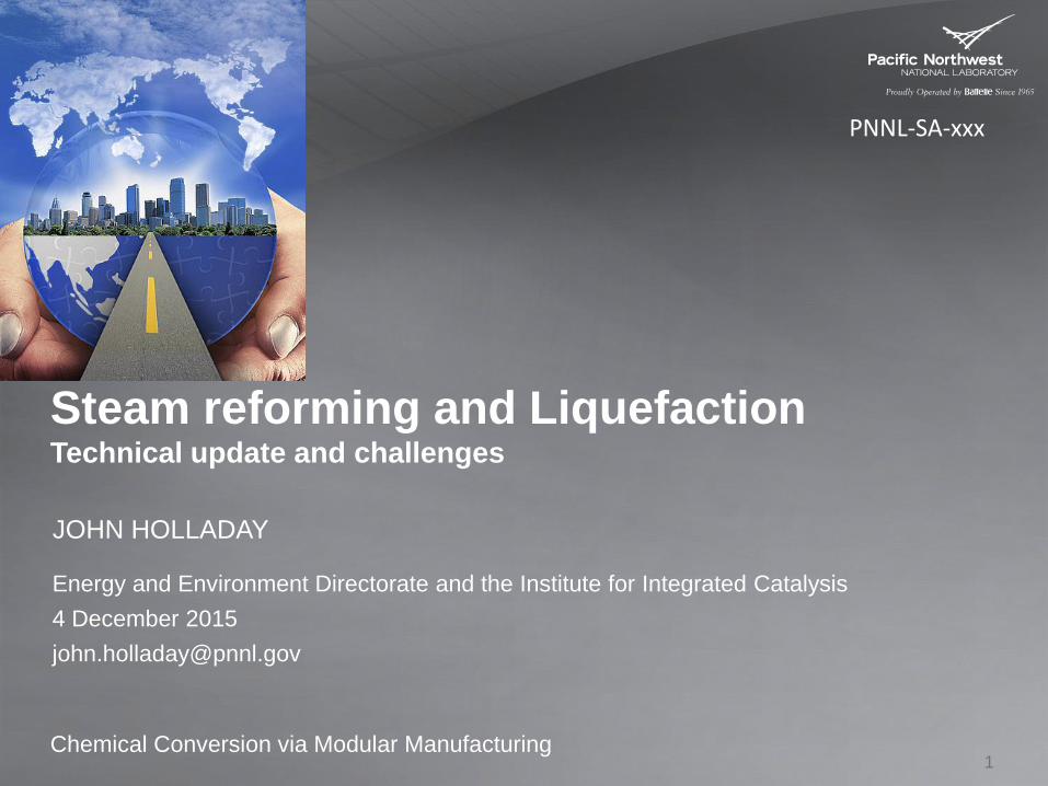
2Courtesy of Velocys®
Industrial steam reforming
Challenges:• Catalyst
• Low cost• High Activity• Loading
• Reactor Design• Headers• Hot/cold points
• Fabrication• High volume• Catalyst • High P operation
Coupling process intensification with modular design
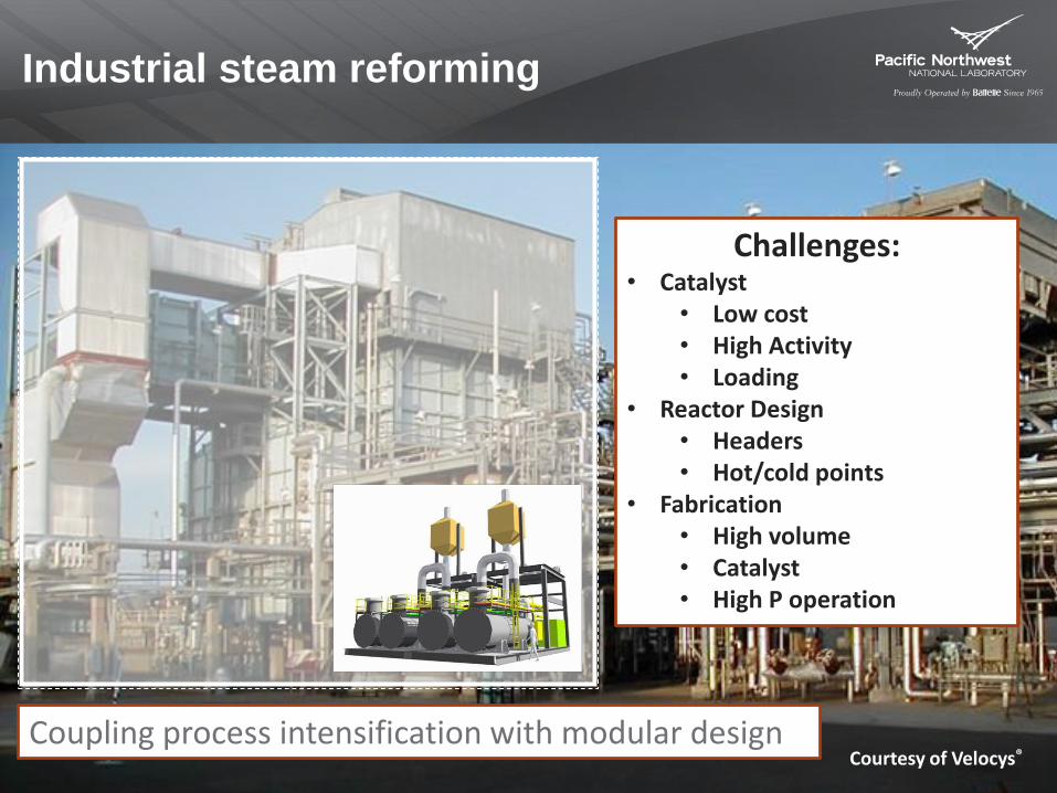
Small modular steam reforming
Advantages
10-100x volume reduction
10x improvement in heat
and mass transfer
Improved reactor control
High integration
Modular/reconfigurable
Challenges
Catalyst
Reactor design
Fabrication
1-2 kW methane Steam Reformer
Portable, distributed power, easily moved
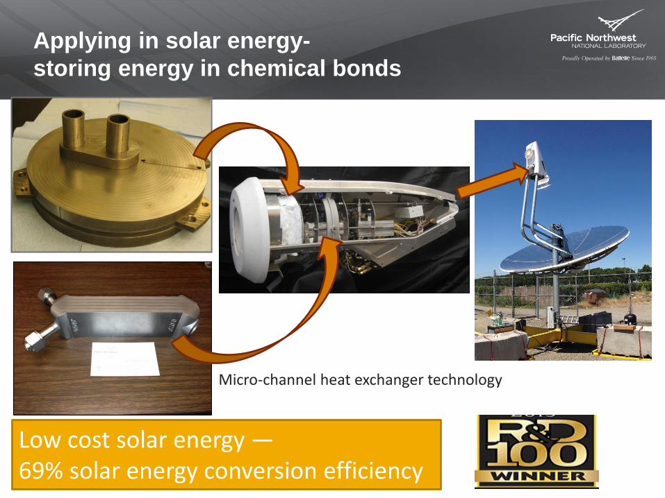
Applying in solar energy-
storing energy in chemical bonds
Micro-channel heat exchanger technology
Low cost solar energy —69% solar energy conversion efficiency
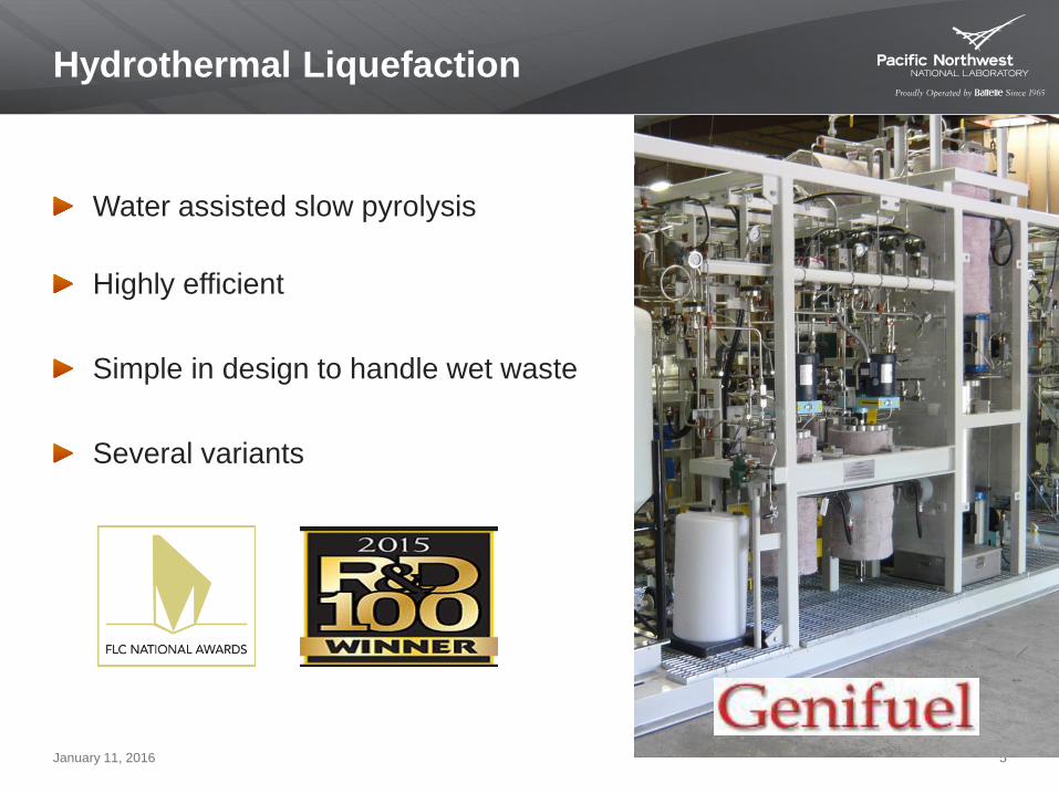
Hydrothermal Liquefaction
Water assisted slow pyrolysis
Highly efficient
Simple in design to handle wet waste
Several variants
January 11, 2016 5
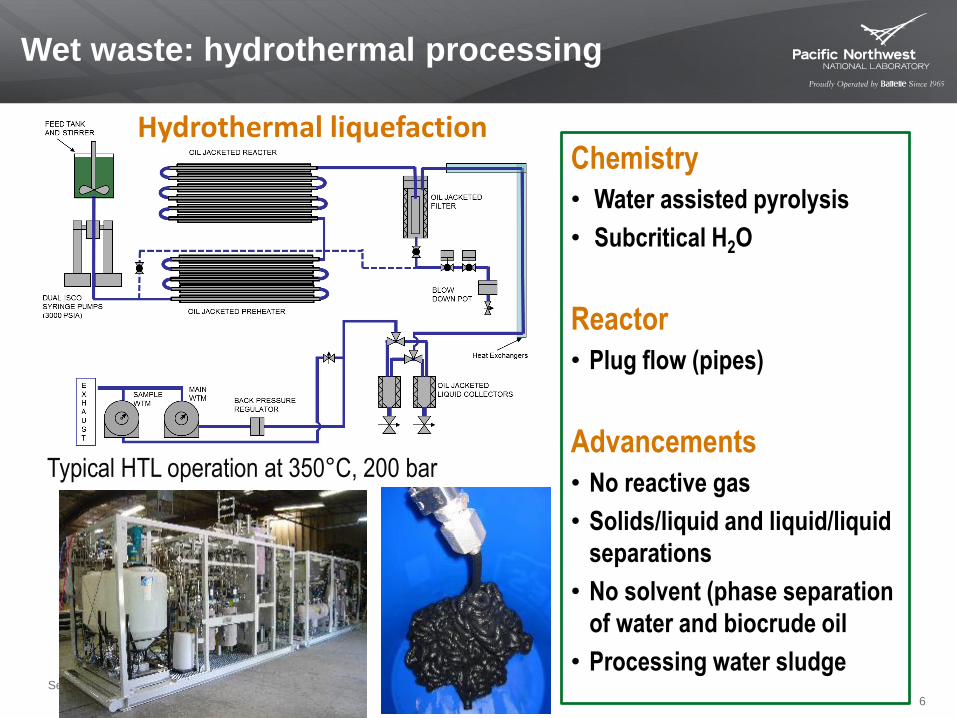
Wet waste: hydrothermal processing
September 16, 2014 6
Typical HTL operation at 350°C, 200 bar
Chemistry
• Water assisted pyrolysis
• Subcritical H2O
Reactor
• Plug flow (pipes)
Advancements
• No reactive gas
• Solids/liquid and liquid/liquid
separations
• No solvent (phase separation
of water and biocrude oil
• Processing water sludge
Hydrothermal liquefaction
6
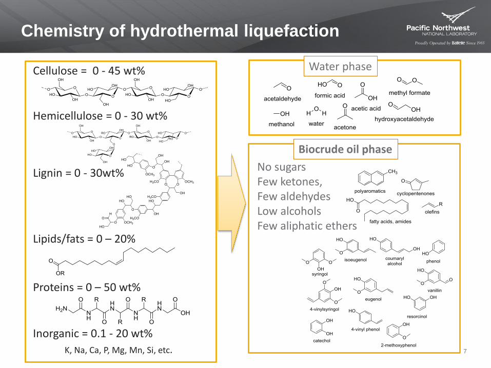
Chemistry of hydrothermal liquefaction
Cellulose = 0 - 45 wt%
Hemicellulose = 0 - 30 wt%
Lignin = 0 - 30wt%
K, Na, Ca, P, Mg, Mn, Si, etc.
Inorganic = 0.1 - 20 wt%
Water phase
No sugarsFew ketones,Few aldehydesLow alcoholsFew aliphatic ethers
Lipids/fats = 0 – 20%
Biocrude oil phase
Proteins = 0 – 50 wt%
7
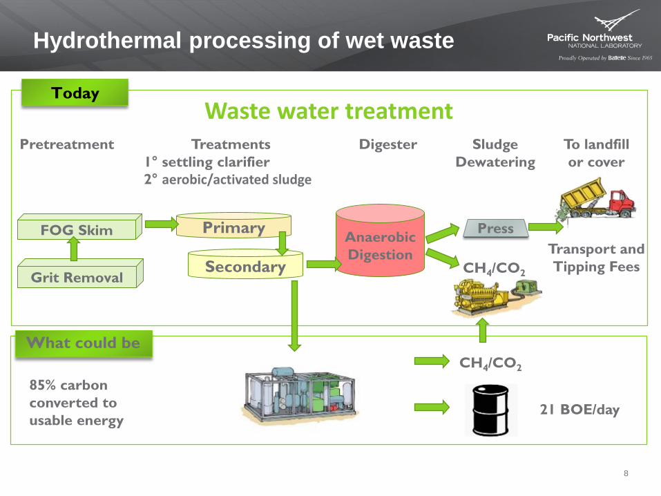
Hydrothermal processing of wet waste
8
Grit Removal
PrimaryFOG Skim
Secondary
Anaerobic
Digestion
Pretreatment Treatments
1° settling clarifier
2° aerobic/activated sludge
Digester Sludge
Dewatering
Transport and
Tipping FeesCH4/CO2
Waste water treatment
Press
To landfill
or cover
Today
What could be
CH4/CO2
21 BOE/day
85% carbon
converted to
usable energy
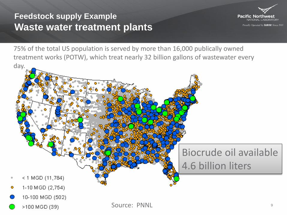
Feedstock supply Example
Waste water treatment plants
9Source: PNNL
Biocrude oil available4.6 billion liters
75% of the total US population is served by more than 16,000 publically owned treatment works (POTW), which treat nearly 32 billion gallons of wastewater every day.
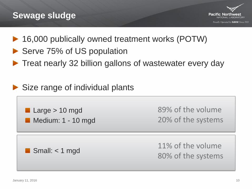
Sewage sludge
16,000 publically owned treatment works (POTW)
Serve 75% of US population
Treat nearly 32 billion gallons of wastewater every day
Size range of individual plants
Large > 10 mgd
Medium: 1 - 10 mgd
Small: < 1 mgd
January 11, 2016 10
89% of the volume20% of the systems
11% of the volume80% of the systems
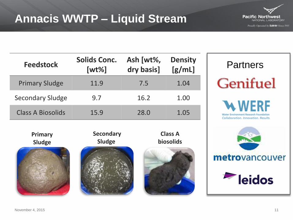
Annacis WWTP – Liquid Stream
November 4, 2015 11
Partners
Primary Sludge
Secondary Sludge
FeedstockSolids Conc.
[wt%]Ash [wt%,dry basis]
Density[g/mL]
Primary Sludge 11.9 7.5 1.04
Secondary Sludge 9.7 16.2 1.00
Class A Biosolids 15.9 28.0 1.05
Class Abiosolids
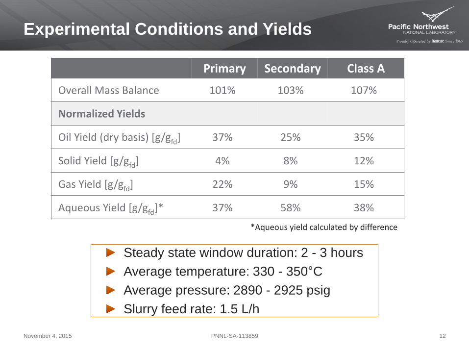
Experimental Conditions and Yields
Steady state window duration: 2 - 3 hours
Average temperature: 330 - 350°C
Average pressure: 2890 - 2925 psig
Slurry feed rate: 1.5 L/h
November 4, 2015 12PNNL-SA-113859
Primary Secondary Class A
Overall Mass Balance 101% 103% 107%
Normalized Yields
Oil Yield (dry basis) [g/gfd] 37% 25% 35%
Solid Yield [g/gfd] 4% 8% 12%
Gas Yield [g/gfd] 22% 9% 15%
Aqueous Yield [g/gfd]* 37% 58% 38%
*Aqueous yield calculated by difference
November 4, 2015 PNNL-SA-113859 13
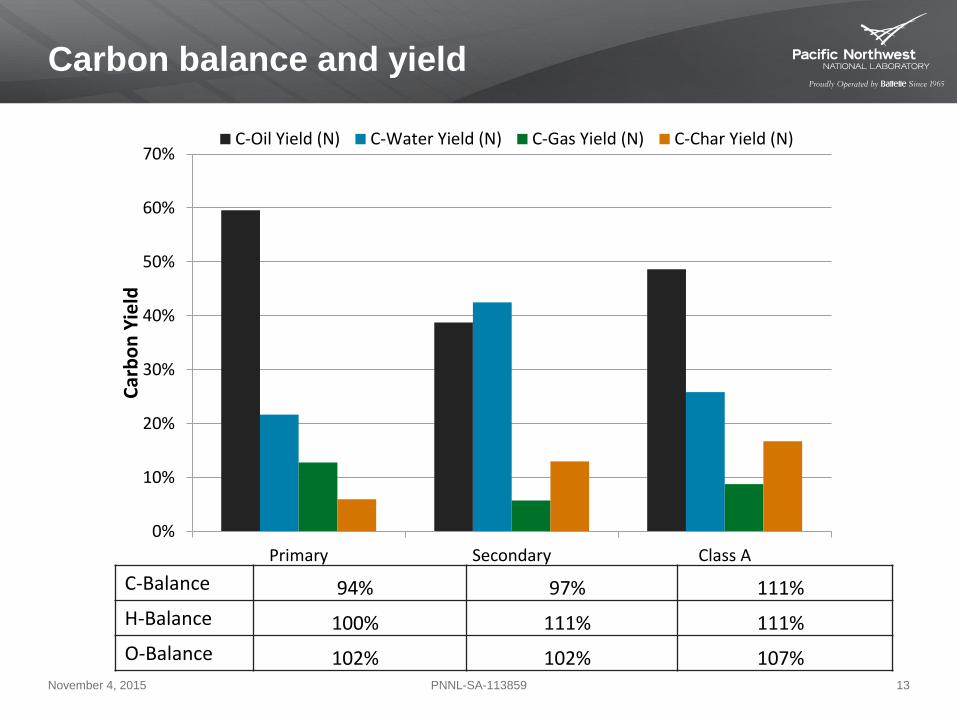
Carbon balance and yield
C-Balance 94% 97% 111%
H-Balance 100% 111% 111%
O-Balance 102% 102% 107%
0%
10%
20%
30%
40%
50%
60%
70%
Primary Secondary Class A
Car
bo
n Y
ield
C-Oil Yield (N) C-Water Yield (N) C-Gas Yield (N) C-Char Yield (N)
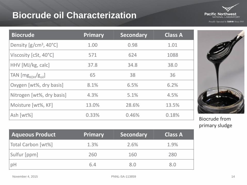
Biocrude oil Characterization
November 4, 2015 14PNNL-SA-113859
Biocrude Primary Secondary Class A
Density [g/cm3, 40°C] 1.00 0.98 1.01
Viscosity [cSt, 40°C] 571 624 1088
HHV [MJ/kg, calc] 37.8 34.8 38.0
TAN [mgKOH/goil] 65 38 36
Oxygen [wt%, dry basis] 8.1% 6.5% 6.2%
Nitrogen [wt%, dry basis] 4.3% 5.1% 4.5%
Moisture [wt%, KF] 13.0% 28.6% 13.5%
Ash [wt%] 0.33% 0.46% 0.18%
Aqueous Product Primary Secondary Class A
Total Carbon [wt%] 1.3% 2.6% 1.9%
Sulfur [ppm] 260 160 280
pH 6.4 8.0 8.0
Biocrude from primary sludge
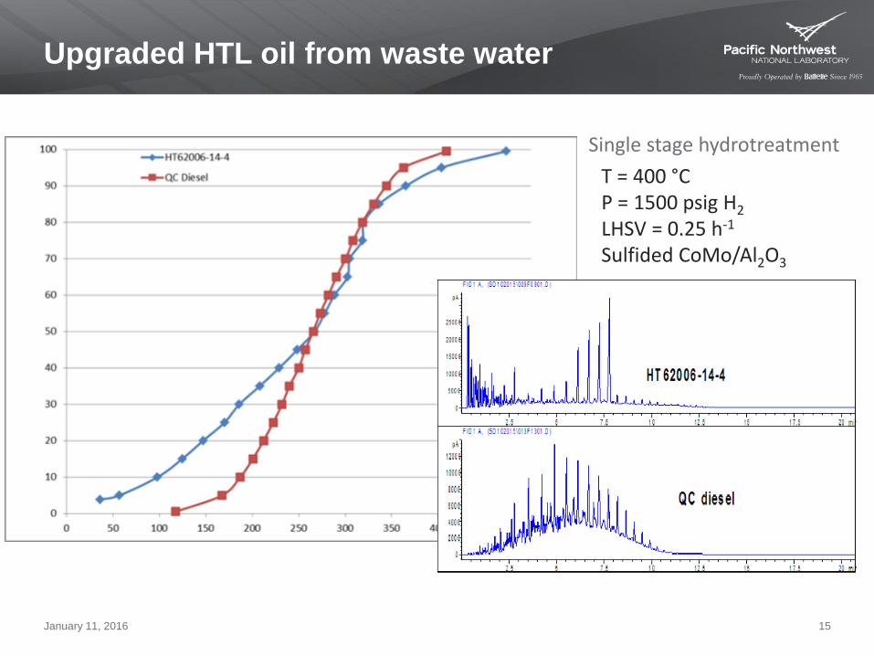
Upgraded HTL oil from waste water
January 11, 2016 15
Single stage hydrotreatment
T = 400 °CP = 1500 psig H2
LHSV = 0.25 h-1
Sulfided CoMo/Al2O3
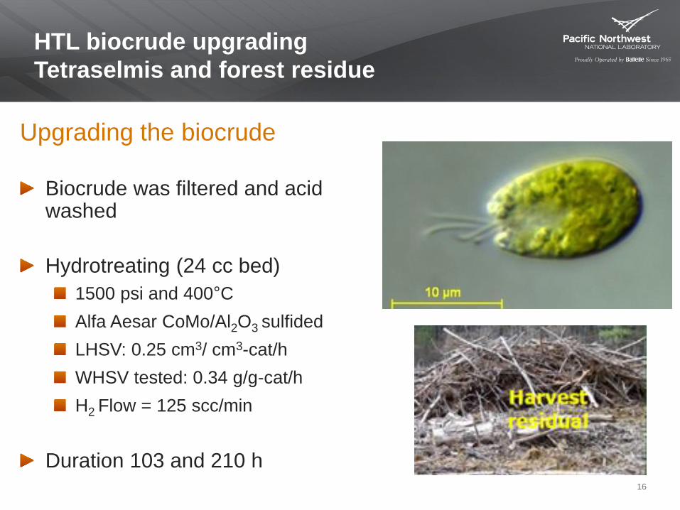
HTL biocrude upgrading
Tetraselmis and forest residue
16
Upgrading the biocrude
Biocrude was filtered and acid washed
Hydrotreating (24 cc bed)
1500 psi and 400°C
Alfa Aesar CoMo/Al2O3 sulfided
LHSV: 0.25 cm3/ cm3-cat/h
WHSV tested: 0.34 g/g-cat/h
H2 Flow = 125 scc/min
Duration 103 and 210 h
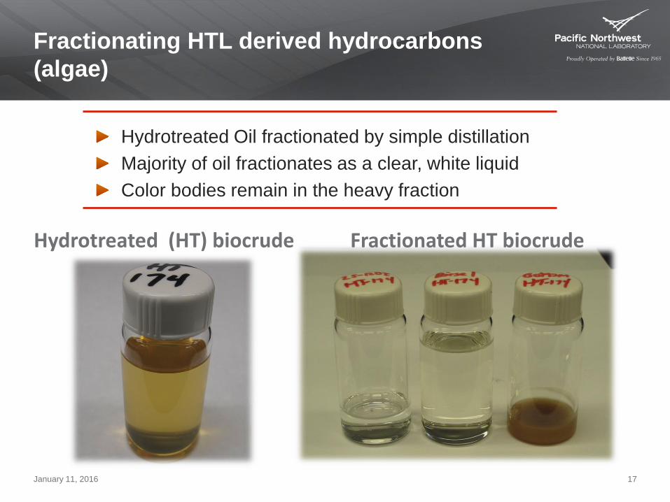
Fractionating HTL derived hydrocarbons
(algae)
January 11, 2016 17
Hydrotreated Oil fractionated by simple distillation
Majority of oil fractionates as a clear, white liquid
Color bodies remain in the heavy fraction
Hydrotreated (HT) biocrude Fractionated HT biocrude
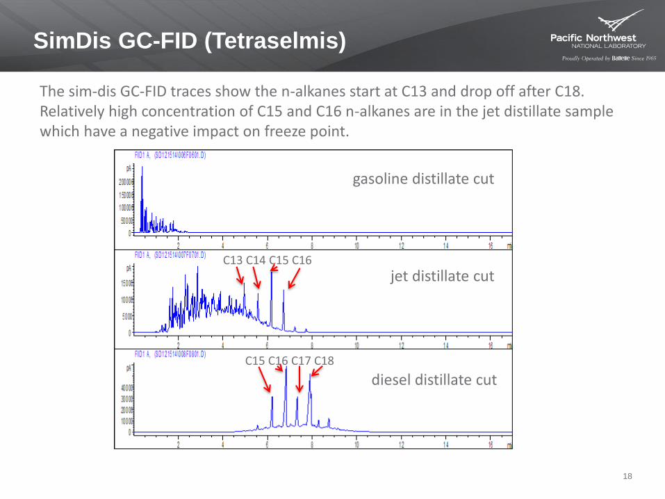
SimDis GC-FID (Tetraselmis)
18
The sim-dis GC-FID traces show the n-alkanes start at C13 and drop off after C18. Relatively high concentration of C15 and C16 n-alkanes are in the jet distillate sample which have a negative impact on freeze point.
jet distillate cut
gasoline distillate cut
diesel distillate cut
C13 C14 C15 C16
C15 C16 C17 C18
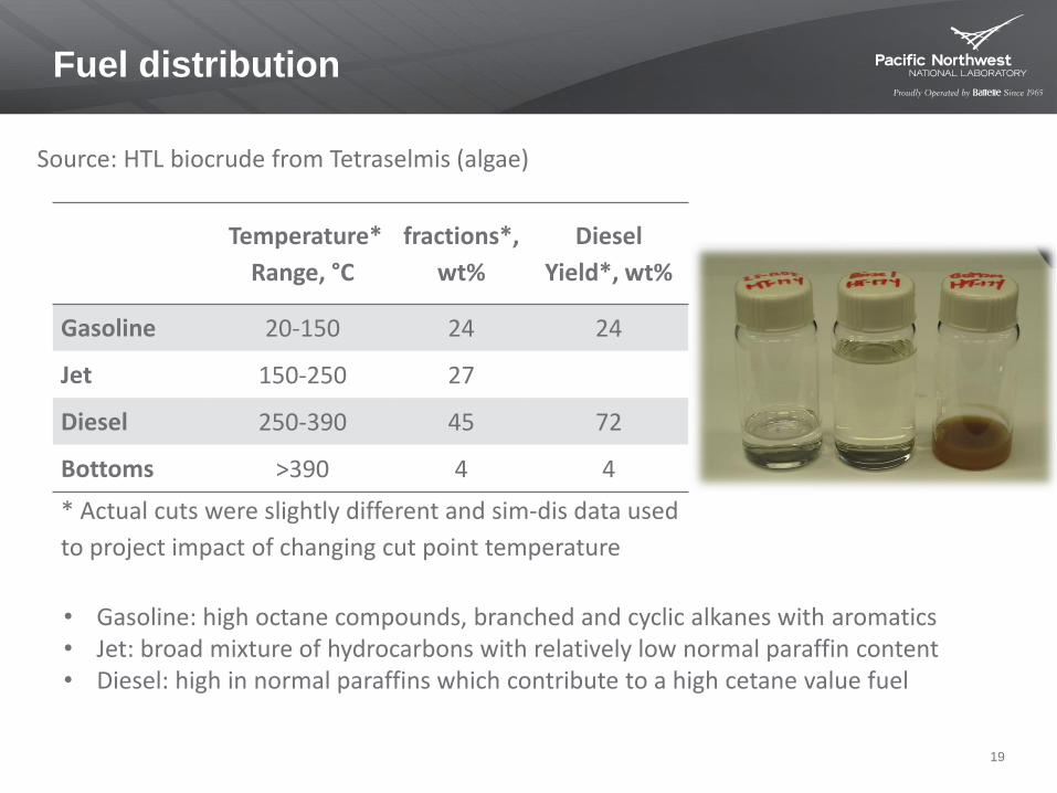
Fuel distribution
19
Temperature*
Range, °C
fractions*,
wt%
Diesel
Yield*, wt%
Gasoline 20-150 24 24
Jet 150-250 27
Diesel 250-390 45 72
Bottoms >390 4 4
* Actual cuts were slightly different and sim-dis data used
to project impact of changing cut point temperature
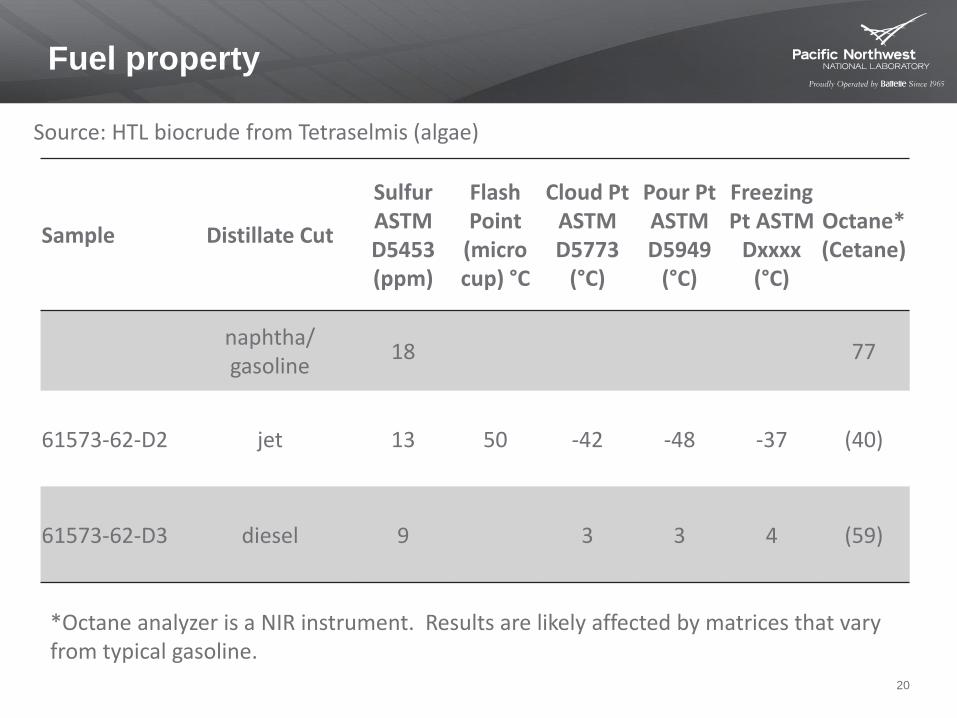
Source: HTL biocrude from Tetraselmis (algae)
• Gasoline: high octane compounds, branched and cyclic alkanes with aromatics • Jet: broad mixture of hydrocarbons with relatively low normal paraffin content• Diesel: high in normal paraffins which contribute to a high cetane value fuel
Fuel property
20
Sample Distillate Cut
Sulfur ASTM D5453 (ppm)
Flash Point
(micro cup) °C
Cloud Pt ASTM D5773
(°C)
Pour Pt ASTM D5949
(°C)
Freezing Pt ASTM
Dxxxx (°C)
Octane*(Cetane)
naphtha/ gasoline
18 77
61573-62-D2 jet 13 50 -42 -48 -37 (40)
61573-62-D3 diesel 9 3 3 4 (59)
*Octane analyzer is a NIR instrument. Results are likely affected by matrices that vary from typical gasoline.
Source: HTL biocrude from Tetraselmis (algae)
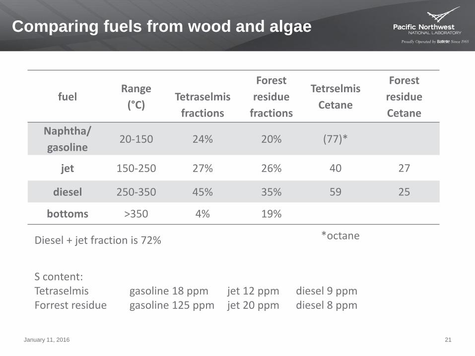
Comparing fuels from wood and algae
January 11, 2016 21
fuelRange
(°C)Tetraselmis
fractions
Forest
residue
fractions
Tetrselmis
Cetane
Forest
residue
Cetane
Naphtha/
gasoline20-150 24% 20% (77)*
jet 150-250 27% 26% 40 27
diesel 250-350 45% 35% 59 25
bottoms >350 4% 19%
S content:Tetraselmis gasoline 18 ppm jet 12 ppm diesel 9 ppmForrest residue gasoline 125 ppm jet 20 ppm diesel 8 ppm
Diesel + jet fraction is 72% *octane
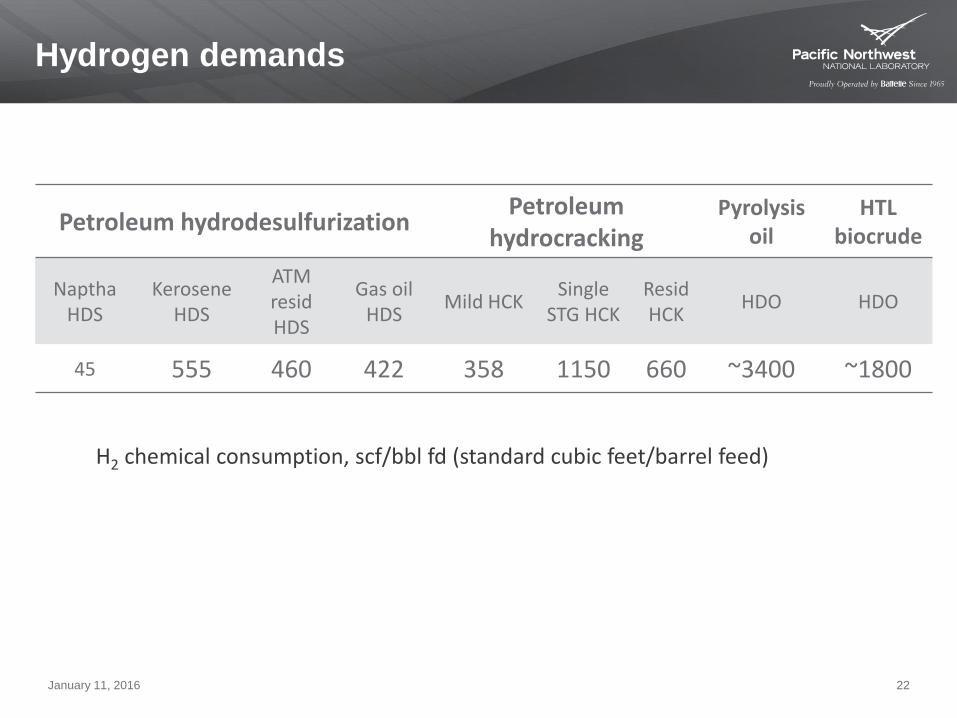
Hydrogen demands
January 11, 2016 22
Petroleum hydrodesulfurizationPetroleum
hydrocrackingPyrolysis
oilHTL
biocrude
NapthaHDS
KeroseneHDS
ATM residHDS
Gas oil HDS
Mild HCKSingle
STG HCKResidHCK
HDO HDO
45 555 460 422 358 1150 660 ~3400 ~1800
H2 chemical consumption, scf/bbl fd (standard cubic feet/barrel feed))
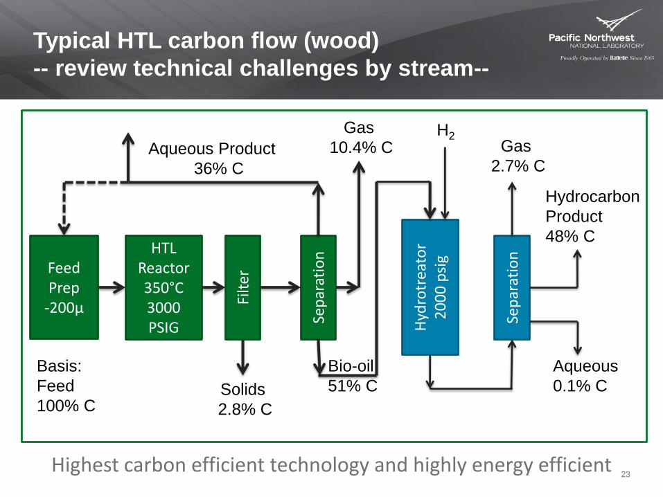
HTL Reactor350°C3000 PSIG
Sep
arat
ion
Filt
er
Hyd
rotr
eato
r2
00
0 p
sig
Feed Prep
-200µ
Sep
arat
ion
Aqueous Product
36% C
Solids
2.8% C
Gas
10.4% C H2
Hydrocarbon
Product
48% C
Gas
2.7% C
Aqueous
0.1% C
Bio-oil
51% C
Basis:
Feed
100% C
Typical HTL carbon flow (wood)
-- review technical challenges by stream--
23Highest carbon efficient technology and highly energy efficient
Conclusions
January 11, 2016 24
Steam reforming
Modularization coupled with
process intensification
Opens new opportunities
Liquefaction
high quality biocrude oil from
complex mixed waste
Technologies intersect
Stable, low cost operation

Back upmaterial
January 11, 2016 25
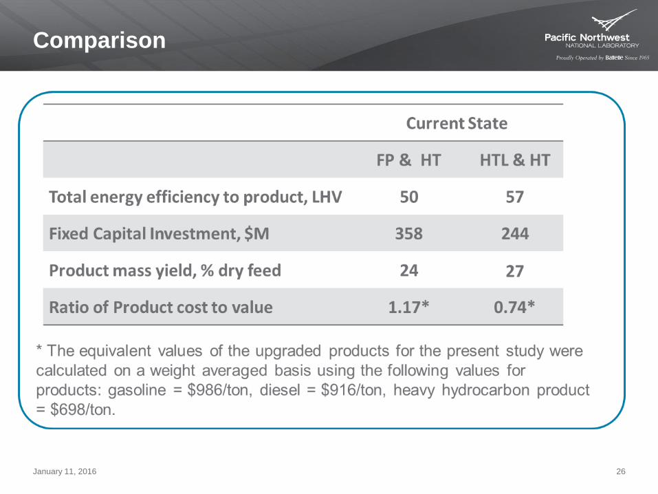
Comparison
January 11, 2016 26
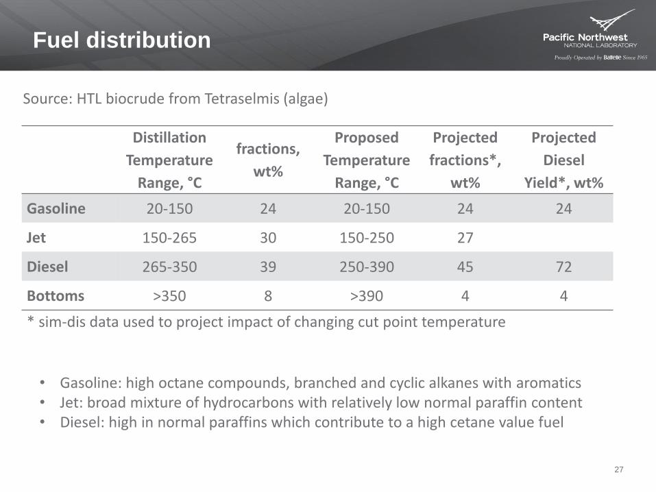
Fuel distribution
27
Distillation
Temperature
Range, °C
fractions,
wt%
Proposed
Temperature
Range, °C
Projected
fractions*,
wt%
Projected
Diesel
Yield*, wt%
Gasoline 20-150 24 20-150 24 24
Jet 150-265 30 150-250 27
Diesel 265-350 39 250-390 45 72
Bottoms >350 8 >390 4 4
* sim-dis data used to project impact of changing cut point temperature
Source: HTL biocrude from Tetraselmis (algae)
• Gasoline: high octane compounds, branched and cyclic alkanes with aromatics • Jet: broad mixture of hydrocarbons with relatively low normal paraffin content• Diesel: high in normal paraffins which contribute to a high cetane value fuel
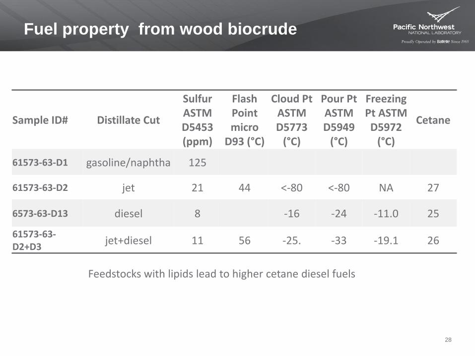
Fuel property from wood biocrude
28
Sample ID# Distillate Cut
Sulfur ASTM D5453 (ppm)
Flash Point micro
D93 (°C)
Cloud Pt ASTM D5773
(°C)
Pour Pt ASTM D5949
(°C)
Freezing Pt ASTM D5972
(°C)
Cetane
61573-63-D1 gasoline/naphtha 125
61573-63-D2 jet 21 44 <-80 <-80 NA 27
6573-63-D13 diesel 8 -16 -24 -11.0 25
61573-63-D2+D3
jet+diesel 11 56 -25. -33 -19.1 26
Feedstocks with lipids lead to higher cetane diesel fuels
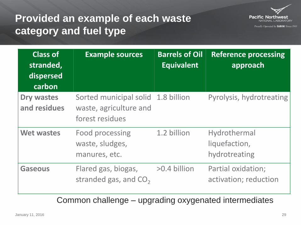
Provided an example of each waste
category and fuel type
January 11, 2016 29
Class of
stranded,
dispersed
carbon
Example sources Barrels of Oil
Equivalent
Reference processing
approach
Dry wastes
and residues
Sorted municipal solid
waste, agriculture and
forest residues
1.8 billion Pyrolysis, hydrotreating
Wet wastes Food processing
waste, sludges,
manures, etc.
1.2 billion Hydrothermal
liquefaction,
hydrotreating
Gaseous Flared gas, biogas,
stranded gas, and CO2
>0.4 billion Partial oxidation;
activation; reduction
Common challenge – upgrading oxygenated intermediates
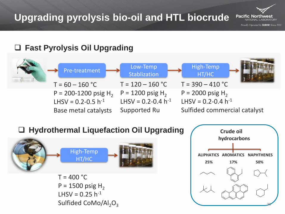
Upgrading pyrolysis bio-oil and HTL biocrude
Fast Pyrolysis Oil Upgrading
Pre-treatmentLow-Temp
StablizationHigh-Temp
HT/HC
T = 60 – 160 °CP = 200-1200 psig H2
LHSV = 0.2-0.5 h-1
Base metal catalysts
T = 120 – 160 °CP = 1200 psig H2
LHSV = 0.2-0.4 h-1
Supported Ru
T = 390 – 410 °CP = 2000 psig H2
LHSV = 0.2-0.4 h-1
Sulfided commercial catalyst
Hydrothermal Liquefaction Oil Upgrading
High-Temp HT/HC
T = 400 °CP = 1500 psig H2
LHSV = 0.25 h-1
Sulfided CoMo/Al2O3
Crude oil
ALIPHATICS AROMATICS NAPHTHENES
25% 17% 50%
hydrocarbons
30
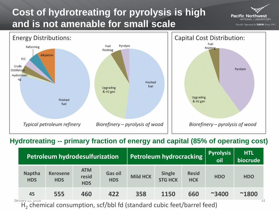
Cost of hydrotreating for pyrolysis is high
and is not amenable for small scale
January 11, 2016 31
Hydrotreating -- primary fraction of energy and capital (85% of operating cost)
Energy Distributions:
Biorefinery – pyrolysis of wood
Capital Cost Distribution:
Biorefinery – pyrolysis of woodTypical petroleum refinery
Petroleum hydrodesulfurization Petroleum hydrocrackingPyrolysis
oilHTL
biocrude
NapthaHDS
KeroseneHDS
ATM residHDS
Gas oil HDS
Mild HCKSingle
STG HCKResidHCK
HDO HDO
45 555 460 422 358 1150 660 ~3400 ~1800
H2 chemical consumption, scf/bbl fd (standard cubic feet/barrel feed))
![Oxidative Steam Reforming of Bioethanol over …...as a support in the ethanol steam-reforming reactions [17]. Rh, Ru and Abstract Oxidative steam reforming of ethanol for hydrogen](https://img.dokumen.tips/doc/110x75/5e780744e9502758d52e3186/oxidative-steam-reforming-of-bioethanol-over-as-a-support-in-the-ethanol-steam-reforming.jpg)