Embed Size (px)
Citation preview

Cooling & Heating Division
120 TR to 2500 TR (420 kW to 8775 kW)
Steam Driven Vapour Absorption Chiller

Vapor Absorption Technology from Thermax is at work for clients in more than 50 industries including Pharmaceuticals, Chemicals, Fertilizers, Steel, Textiles, Petrochemicals, Food & Beverages and Automobile industries as well as in Hotels, Commercial Complexes, Shopping Complexes, Office Buildings, Educational Institutes, Airports, Cinema halls and Medical Centers.
Manufacturing capabilities of Thermax’s Cooling SBU are confirmed by the fact that, over the years, Thermax has installed thousands of machines in more than 70 countries including USA, Brazil, Germany, Spain, UK, Italy, UAE, Saudi Arabia, India, China, Australia, Thailand, Philippines, Malaysia, Russia and Nigeria with the products conforming to the respective country standards like ETL, CE, TUV, DNV, ASME etc. Thermax has its fully owned subsidiaries namely Thermax Inc. in USA, Thermax Europe Limited in UK and Thermax (Zhejiang) Cooling and Heating Engg. Company Limited in China.
Thermax believes in efficient and responsive services to it's clients and exhibits in it's way of business, by giving optimal and quality solutions and achieving customer delight. Thermax has a worldwide sales, service and distribution network to fulfill the needs of it's valuable customers.
The Cooling SBU of THERMAX promotes Vapor Absorption Chillers as a cost effective and environment friendly alternative to electricity driven compression chillers.
It offers expert solutions in Process Chilling & Air Conditioning for industrial as well as commercial applications. Cooling SBU's strength lies in customized solutions as per the requirements of its customers.
Unlike electrical chillers, Absorption Chillers are powered by heat. These machines can run on a variety of heat sources, e.g. steam, hot water, liquid/gaseous fuels, exhaust gases and/or a combination of above.
Cooling & Heating Division - Cooling SBU
To be a globally respected high performance organization offering sustainable solutions in energy and environment.
Vision
From Cooling to Heating, from Power Generation to Air Purification, from Water and Sewage Treatment to Speciality Chemicals, THERMAX Solutions are improving life at work in many ways.
Every year THERMAX helps generate 6,000 MW of Power, produce 100,000 tons of steam, provide 4 billion tons of Cooling and treat 1,000 million litres/day of Water and Waste.
THERMAX today is a major Engineering and Environment company with revenues of USD 800 million and with market capitalization of over USD 1 billion.
THERMAX was one of 20 Indian companies in Forbes list of “Asia’s Best Under a Billion Companies” in 2005 and 2006 and was ranked “No. 1 among the top 21 wealth creators” in India over the last 5 years by a leading investment journal.
THERMAX brings to customers enriched experience of industrial applications, and expertise through technological partnerships and strategic alliances.
Operating from its Headquarters in Pune (Western India), Thermax has built an international sales & service network spread over South East Asia, Middle East, Africa, Russia, UK, US and China. It has full fledged ISO 9001:2000 and ISO 14000 accredited manufacturing setups.
Sustainable Solutions
Corporate office image
Thermax - Conserving Energy,Preserving the Environment

Quality assured manufacturing to international codes
Thermax manufactures environment friendly and energy efficient vapor absorption chillers at its plants in Pune, India, and China. Its state-of-the-art manufacturing facility has been awarded with ISO 9001 and ISO 14001 certifications.
Stringent quality control procedures, along with a skilled workforce, ensure that a highly reliable product leaves the factory. The equipment and manufacturing processes conform to international standards.
Manufacturing & Testing World-Class FacilitiesThermax’s pressure part manufacturing has been approved by ASME and bears the ‘S’, ‘U’, ‘H’ and ‘R’ stamps. The vapor absorption chillers are CE certified for the European Union and ETL listed for the US and Canadian markets. They conform to the Kyoto Protocol and are in absolute tandem with the Clean Development Mechanism code (CDM).
Thermax also conforms to Environmental Management System standard 14001 and OHSAS 18001.
CNC twin spindle drilling machine with high speed and direct feed technology ensures fine tube hole finish and accuracy, which is important for leak tight expansion and effective heat transfer.
A Helium leak detection test ensures there is no leak at welding joints.
Welding robot for high precision automatic welding.
CNC gas cutting machine for plate cutting ensures precision cutting of shell plates and profile cut
tube plates.
Press Brake Machine
Rolling Machine
TES DET
P RD OEI VR ET N l
l
l

Salient Features
for Matchless Reliability, Efficiency and Durability
Advanced Series Flow Cycle
Advanced Series Flow Cycle to avoid simultaneous occurrence of high
temperature and high concentration, thereby minimizing the
probability of corrosion.
Unique Two Stage Evaporation Technology
Thermax chillers are designed based on unique two stage evaporation
technology. This ensures that the specific heat input is one of the
lowest in the industry, resulting in higher cooling output for the same
heat input. Also, larger temperature difference in chilled water to the otune of 30 C, is possible.
Split Absorber Design
Split absorber design helps to improve absorption rate of LiBr, thereby
improving efficiency. This also reduces surface area under cold
insulation.
Gravity Feed LiBr and Refrigerant
Distribution Mechanism
Nozzle-less, non-clogging gravity feed distribution mechanism for
stable and reliable operation throughout the life of the machine. Drop
in performance due to nozzle wear, clogging eliminated. Need for
separate pump for spray eliminated, resulting in lower power
consumption.
Zero Crystallization
Unique State-of-the-Art concentration monitoring and control that
virtually eliminates crystallization and is distinctly different from the
conventional auto de-crystallization. This helps the chiller to operate
even at low cooling water inlet temperature without crystallisation.
Lowest Chilled Water/ Brine Outlet
Temperature
Thermax innovative absorption chillers can deliver leaving chilled owater temperatures down to 3.5 C and leaving chilled brine solution up
oto 0 C, enabling absorption chillers to be used for applications
involving low chilled water / brine temperature.
Best-in-class Coefficient of Performance
Process design to ensure maximum internal Heat recovery to give the
lowest specific steam consumption benefit to the customer.
Highly Efficient and Reliable Solution Heat
Exchangers for Maximum Internal Heat
Recovery
All regenerative heat exchangers are high efficiency plate type heat
exchangers with SS316 plates, for improved reliability.
Welded Plate Heat Exchanger for
Condensate Heat Recovery
Specially designed welded type plate heat exchanger with SS316 plate
used as heat reclaimer for condensate heat recovery. These are best
suited for two phase flow and are highly reliable compared to
conventional brazed heat exchangers.
Isolation Valves for Canned Motor Pumps
Double seal isolation valves and bolted pumps facilitate easy
maintenance of the machine mounted canned motor pumps without
any loss of vacuum in the system. This significantly reduces the down
time of the chiller.
Ferritic Stainless Steel Tubes in Generators
Titanium stabilized ferritic stainless steel tubes (SS430 Ti) used in
both high temperature and low temperature generator for lowest
differential thermal expansion, thereby protecting the tubes from
stress corrosion cracking. Suitable for steam with dissolved ammonia
compounds, where copper alloys are not recommended.
De-oxidised Low Phosphorus Copper Tubes
Copper tubes conforming to ASTM/JIS standards, with phosphorus
content maintained below 0.005 ppm, used in chilled water and
cooling water circuits. This protects the tubes from hydrogen
embrittlement in LiBr environment.
Avenues for COP improvement
Enlargement of Done by all
Two stage evaporation Unique feature of Thermax chillers
Advanced series flow Design unique to Thermax chillers
Refrigerant heat exchanger Unique feature of Thermax chillers
heat transfer area manufacturersParameter Parallel Advanced Flow Series Flow
oHTG Temperature 162 C 155 C
LiBr Concentration 64 - 65% 60.5%
o oLTG Temperature 88 C 90 C
LiBr Concentration 62 - 64% 63%
o

Improved Online Purge System
Factory fitted high efficiency purge system with purge cooler,
continuously removes non-condensable gases from the chiller into the
storage tank while in operation.
PLC Based Control Panel
Thermax chillers are provided with State-of-the-Art PLC based control
panel, user friendly 7 inch touch screen operator interface and data
logging system.
Non-clogging Filters to protect Solution
Heat Exchangers
Stainless steel filters provided on both high temperature and low
temperature generator outlet to safe guard the solution heat
exchangers. Non-clogging design ensures uninterrupted circulation of
lithium bromide, resulting in smooth operation.
Non-toxic Corrosion Inhibitor
New generation non-precipitating, non-toxic molybdenum based
corrosion inhibitor which is more effective than conventional
inhibitors based on Chromate (Cancer causing, prohibited in several
countries) and Nitrate.
Variable Frequency Drive on Absorbent
Pump
Variable Frequency Drive on absorbent pump for higher reliability,
savings in steam & savings in power, during part load operation.
10-100% Stepless Modulation
For cooling loads ranging from 10% to 100% of the designed capacity,
the steam control valve automatically varies steam flow in order to
maintain the temperature of chilled water leaving the chiller.
Multi-stage Level Control
Multiple stage level control in three locations enables effective
operation during part load and prevents cavitation of refrigerant and
absorbent pumps.
BAS/ DCS Connectivity
Direct connectivity of machine PLC panel with Third party monitoring
systems like BAS (Building Automation System), DCS (Distributed
Control System) or PLC (Programmable Logic Controller) can be
provided via Modbus RTU protocol on RS485 network.
Partload Curve - With Invertor(For indicative purpose only)
% Cooling Load
% S
peci
fic
Ste
am C
onsu
mpt
ion
101
100
99
98
97
96
95
94
93
9230 40 50 60 70 80 90 100
PU
RG
E D
EVIC
E
EVAP
LTG
ABSO
COND
ABSO
STEAM INLET
s
s
CHW INABSO PUMP
REF PUMP
PURGEPUMP
HTG
SCV OPENING :
12.0 °C
CHW OUT -
COW IN
32.0 °C
COW OUT -
SPRAY -
DHE
LTHE
HTHE
HR
COOLING CAPACITY :
REF LEVEL -
ABSO LEVEL -
HTG LEVEL -
7.0 °C
54.5 °C
37.2 °C
NORMAL
NORMAL
NORMAL
1435.0 TR 85.0
AUTO BLOW DOWN SV - CLOSE CONDENSATE SV - CLOSE
HTG OUT
152.0 °CLTG OUT - 91.0 °C
HTG VAPOUR - 98.5 °C
ABSORBENT PUMP - ON REFRIGERANT PUMP - ON VACUUM PUMP - OFF
REF. OUT - 39.0 °C
63.1LIBR CONC. :

Pumps Controls
Instruments
HMI
PLC
SAFETIES
MOTOR PROTECTION
ŸAbsorbent pump overload relay
ŸRefrigerant pump overload relay
ŸVacuum pump overload relay
CRYSTALLISATIONPREVENTION
Ÿ Concentration MeasurementŸ Cooling water low
temperatureŸ Generator high temperature
ANTI FREEZEPROTECTION
Ÿ Chilled water flow switch
Ÿ Chilled water DP switch
Ÿ Chilled water pump interlock
CAVITATIONPROTECTION
Ÿ Absorber level measurement
Ÿ Evaporator level measurement
Ÿ HTG Level measurement
Customized Offering
Tailor Made, High Efficiency Solutions for Low Steam Pressure
Double effect lithium bromide absorption chillers can be offered for steam pressures as low as 3.0 kg/cm²(g), where conventionally single effect chillers are used.
LiBr Absorption Chillers for Sub-Zero Cooling Applications
Double effect Lithium bromide absorption chillers can be offered for oleaving brine temperatures as low as -5.0 C, offering great savings in
operating costs.
Stand-by Pumps
For critical applications where scheduled maintenance of pumps cannot be carried out, stand-by absorbent, refrigerant and/or vacuum pump can be provided.
Fully Automatic Purging
The automatic purging system eliminates the need for periodic monitoring of purge tank pressure and operation of purge system.
Special Tube Metallurgy
Special tube materials like Cupro-Nickel, Stainless Steel or Titanium depending on water quality on site. This not only improves the reliability & efficiency but also makes the chiller suitable for special applications involving sea water and brackish water.
THERMMONITOR - Remote Performance Monitoring System (RPMS)
Advanced feature that monitors the chiller performance & provides data via internet. This feature enables the facility manager or Thermax engineer to monitor the performance remotely. It offers features like e-log book, status, trends, abnormal maintenance schedules, alerts etc.
Multi Sectional Shipment Arrangement
For convenience of shipping, the absorption chillers can be shipped in two or more sections depending upon the site requirement. This is particularly convenient arrangement for retrofit / replacement jobs.
Instrumentation and Safety Features
LOG
SUPERTHERMAX SERVER
GU
RU
REPORTRuntime & Maintenance Reports
NOTIFTAlerts & Notifications
GPRS
THERMAX CHILLER
Flow meter
4-20mA
Distributed Almodule
modbus
Thermax service support TCA service support
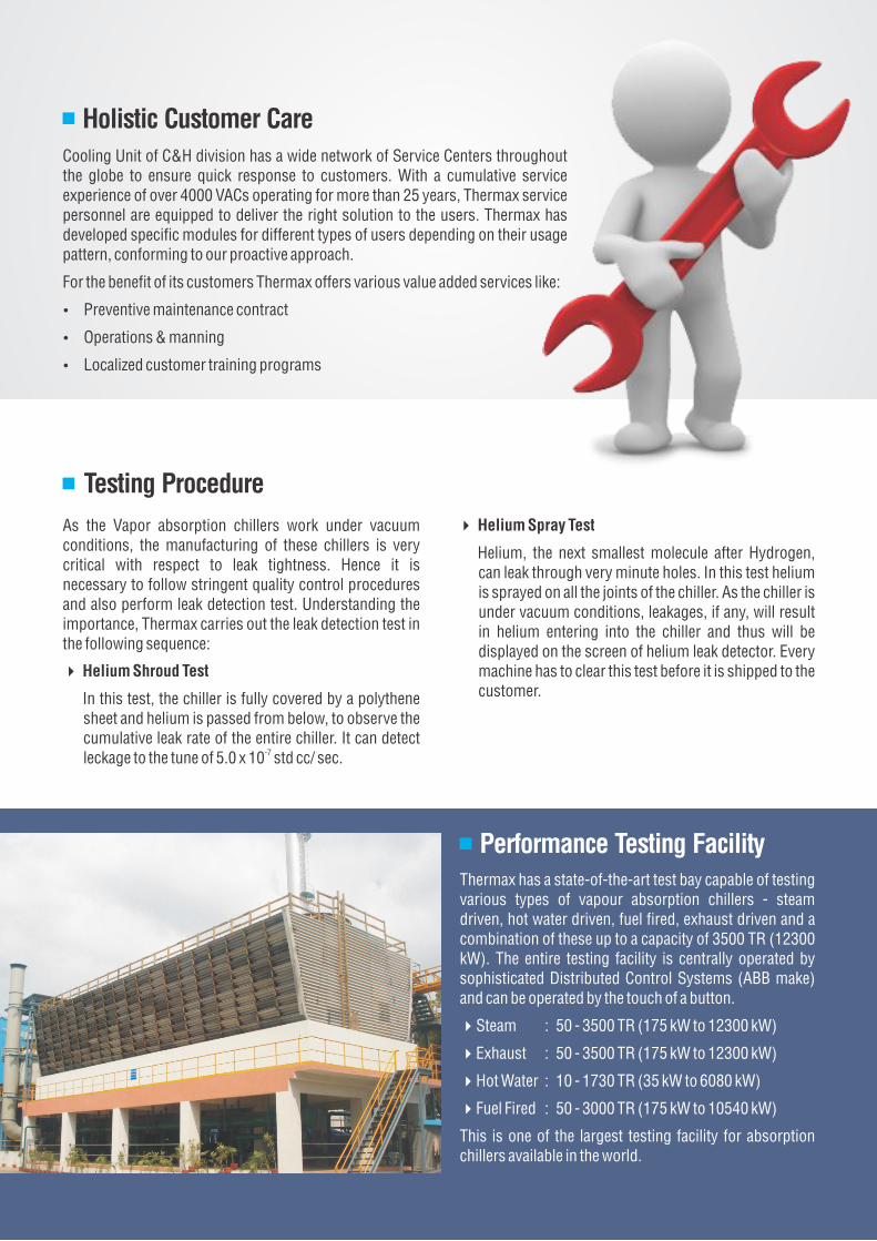
4 Helium Spray Test
Helium, the next smallest molecule after Hydrogen, can leak through very minute holes. In this test helium is sprayed on all the joints of the chiller. As the chiller is under vacuum conditions, leakages, if any, will result in helium entering into the chiller and thus will be displayed on the screen of helium leak detector. Every machine has to clear this test before it is shipped to the customer.
Thermax has a state-of-the-art test bay capable of testing various types of vapour absorption chillers - steam driven, hot water driven, fuel fired, exhaust driven and a combination of these up to a capacity of 3500 TR (12300 kW). The entire testing facility is centrally operated by sophisticated Distributed Control Systems (ABB make) and can be operated by the touch of a button.
4Steam : 50 - 3500 TR (175 kW to 12300 kW)
4Exhaust : 50 - 3500 TR (175 kW to 12300 kW)
4Hot Water : 10 - 1730 TR (35 kW to 6080 kW)
4Fuel Fired : 50 - 3000 TR (175 kW to 10540 kW)
This is one of the largest testing facility for absorption chillers available in the world.
Performance Testing Facility
Testing Procedure
As the Vapor absorption chillers work under vacuum conditions, the manufacturing of these chillers is very critical with respect to leak tightness. Hence it is necessary to follow stringent quality control procedures and also perform leak detection test. Understanding the importance, Thermax carries out the leak detection test in the following sequence:
Helium Shroud Test
In this test, the chiller is fully covered by a polythene sheet and helium is passed from below, to observe the cumulative leak rate of the entire chiller. It can detect
-7leckage to the tune of 5.0 x 10 std cc/ sec.
4
Holistic Customer Care
Cooling Unit of C&H division has a wide network of Service Centers throughout the globe to ensure quick response to customers. With a cumulative service experience of over 4000 VACs operating for more than 25 years, Thermax service personnel are equipped to deliver the right solution to the users. Thermax has developed specific modules for different types of users depending on their usage pattern, conforming to our proactive approach.
For the benefit of its customers Thermax offers various value added services like:
Ÿ Preventive maintenance contract
Ÿ Operations & manning
Ÿ Localized customer training programs
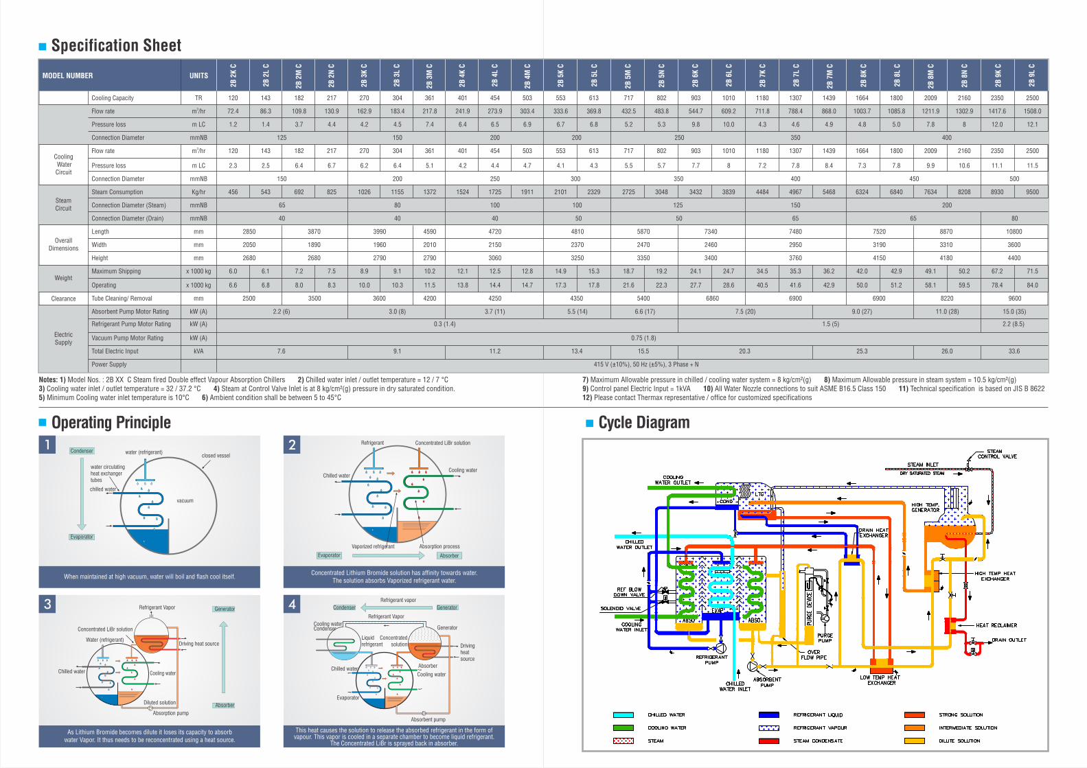
Specification Sheet
Operating Principle
Notes: 1) Model Nos. : 2B XX C Steam fired Double effect Vapour Absorption Chillers 2) Chilled water inlet / outlet temperature = 12 / 7 °C3) Cooling water inlet / outlet temperature = 32 / 37.2 °C 4) Steam at Control Valve Inlet is at 8 kg/cm²(g) pressure in dry saturated condition. 5) Minimum Cooling water inlet temperature is 10°C 6) Ambient condition shall be between 5 to 45°C
3
As Lithium Bromide becomes dilute it loses its capacity to absorb water Vapor. It thus needs to be reconcentrated using a heat source.
Chilled water
Water (refrigerant)
Concentrated LiBr solution
Refrigerant Vapor
Driving heat source
Diluted solution
Absorption pump
Cooling water
Absorber
Generator
This heat causes the solution to release the absorbed refrigerant in the form of vapour. This vapor is cooled in a separate chamber to become liquid refrigerant.
The Concentrated LiBr is sprayed back in absorber.
Condenser
Refrigerant Vapor
Generator
Liquid refrigerant
Concentrated solution Driving
heat source
Chilled waterAbsorber
Cooling water
Evaporator
Absorbent pump
Cooling water
GeneratorCondenser
Refrigerant vapor
4
When maintained at high vacuum, water will boil and flash cool itself.
water (refrigerant)
water circulating heat exchanger tubes
chilled water
closed vessel
vacuum
Evaporator
Condenser1
Concentrated Lithium Bromide solution has affinity towards water. The solution absorbs Vaporized refrigerant water.
2
Chilled water
Refrigerant Concentrated LiBr solution
Cooling water
Absorption processVaporized refrigerant
Evaporator Absorber
Chilled Water Circuit
Cooling Water Circuit
Steam Circuit
Overall Dimensions
Weight
Clearance
Electric Supply
MODEL NUMBER UNITS
Cooling Capacity TR 120 143 182 217 270 304 361 401 454 503 553 613 717 802 903 1010 1180 1307 1439 1664 1800 2009 2160 2350 2500
3Flow rate m /hr 72.4 86.3 109.8 130.9 162.9 183.4 217.8 241.9 273.9 303.4 333.6 369.8 432.5 483.8 544.7 609.2 711.8 788.4 868.0 1003.7 1085.8 1211.9 1302.9 1417.6 1508.0
Pressure loss m LC 1.2 1.4 3.7 4.4 4.2 4.5 7.4 6.4 6.5 6.9 6.7 6.8 5.2 5.3 9.8 10.0 4.3 4.6 4.9 4.8 5.0 7.8 8 12.0 12.1
Connection Diameter mmNB 125 150 200 200 250 350 400
3Flow rate m /hr 120 143 182 217 270 304 361 401 454 503 553 613 717 802 903 1010 1180 1307 1439 1664 1800 2009 2160 2350 2500
Pressure loss m LC 2.3 2.5 6.4 6.7 6.2 6.4 5.1 4.2 4.4 4.7 4.1 4.3 5.5 5.7 7.7 8 7.2 7.8 8.4 7.3 7.8 9.9 10.6 11.1 11.5
Connection Diameter mmNB 150 200 250 300 350 400 450 500
Steam Consumption Kg/hr 456 543 692 825 1026 1155 1372 1524 1725 1911 2101 2329 2725 3048 3432 3839 4484 4967 5468 6324 6840 7634 8208 8930 9500
Connection Diameter (Steam) mmNB 65 80 100 100 125 150 200
Connection Diameter (Drain) mmNB 40 40 40 50 50 65 65 80
Length mm 2850 3870 3990 4590 4720 4810 5870 7340 7480 7520 8870 10800
Width mm 2050 1890 1960 2010 2150 2370 2470 2460 2950 3190 3310 3600
Height mm 2680 2680 2790 2790 3060 3250 3350 3400 3760 4150 4180 4400
Maximum Shipping x 1000 kg 6.0 6.1 7.2 7.5 8.9 9.1 10.2 12.1 12.5 12.8 14.9 15.3 18.7 19.2 24.1 24.7 34.5 35.3 36.2 42.0 42.9 49.1 50.2 67.2 71.5
Operating x 1000 kg 6.6 6.8 8.0 8.3 10.0 10.3 11.5 13.8 14.4 14.7 17.3 17.8 21.6 22.3 27.7 28.6 40.5 41.6 42.9 50.0 51.2 58.1 59.5 78.4 84.0
Tube Cleaning/ Removal mm 2500 3500 3600 4200 4250 4350 5400 6860 6900 6900 8220 9600
Absorbent Pump Motor Rating kW (A) 2.2 (6) 3.0 (8) 3.7 (11) 5.5 (14) 6.6 (17) 7.5 (20) 9.0 (27) 11.0 (28) 15.0 (35)
Refrigerant Pump Motor Rating kW (A) 0.3 (1.4) 1.5 (5) 2.2 (8.5)
Vacuum Pump Motor Rating kW (A) 0.75 (1.8)
Total Electric Input kVA 7.6 9.1 11.2 13.4 15.5 20.3 25.3 26.0 33.6
Power Supply 415 V (±10%), 50 Hz (±5%), 3 Phase + N
2B 2
K C
2B 2
L C
2B 2
M C
2B 2
N C
2B 3
K C
2B 3
L C
2B 3
M C
2B 4
K C
2B 4
L C
2B 4
M C
Cycle Diagram
7) Maximum Allowable pressure in chilled / cooling water system = 8 kg/cm²(g) 8) Maximum Allowable pressure in steam system = 10.5 kg/cm²(g) 9) Control panel Electric Input = 1kVA 10) All Water Nozzle connections to suit ASME B16.5 Class 150 11) Technical specification is based on JIS B 8622 12) Please contact Thermax representative / office for customized specifications
Cooling Capacity TR 120 143 182 217 270 304 361 401 454 503 553 613 717 802 903 1010 1180 1307 1439 1664 1800 2009 2160 2350 2500
3Flow rate m /hr 72.4 86.3 109.8 130.9 162.9 183.4 217.8 241.9 273.9 303.4 333.6 369.8 432.5 483.8 544.7 609.2 711.8 788.4 868.0 1003.7 1085.8 1211.9 1302.9 1417.6 1508.0
Pressure loss m LC 1.2 1.4 3.7 4.4 4.2 4.5 7.4 6.4 6.5 6.9 6.7 6.8 5.2 5.3 9.8 10.0 4.3 4.6 4.9 4.8 5.0 7.8 8 12.0 12.1
Connection Diameter mmNB 125 150 200 200 250 350 400
3Flow rate m /hr 120 143 182 217 270 304 361 401 454 503 553 613 717 802 903 1010 1180 1307 1439 1664 1800 2009 2160 2350 2500
Pressure loss m LC 2.3 2.5 6.4 6.7 6.2 6.4 5.1 4.2 4.4 4.7 4.1 4.3 5.5 5.7 7.7 8 7.2 7.8 8.4 7.3 7.8 9.9 10.6 11.1 11.5
Connection Diameter mmNB 150 200 250 300 350 400 450 500
Steam Consumption Kg/hr 456 543 692 825 1026 1155 1372 1524 1725 1911 2101 2329 2725 3048 3432 3839 4484 4967 5468 6324 6840 7634 8208 8930 9500
Connection Diameter (Steam) mmNB 65 80 100 100 125 150 200
Connection Diameter (Drain) mmNB 40 40 40 50 50 65 65 80
Length mm 2850 3870 3990 4590 4720 4810 5870 7340 7480 7520 8870 10800
Width mm 2050 1890 1960 2010 2150 2370 2470 2460 2950 3190 3310 3600
Height mm 2680 2680 2790 2790 3060 3250 3350 3400 3760 4150 4180 4400
Maximum Shipping x 1000 kg 6.0 6.1 7.2 7.5 8.9 9.1 10.2 12.1 12.5 12.8 14.9 15.3 18.7 19.2 24.1 24.7 34.5 35.3 36.2 42.0 42.9 49.1 50.2 67.2 71.5
Operating x 1000 kg 6.6 6.8 8.0 8.3 10.0 10.3 11.5 13.8 14.4 14.7 17.3 17.8 21.6 22.3 27.7 28.6 40.5 41.6 42.9 50.0 51.2 58.1 59.5 78.4 84.0
Tube Cleaning/ Removal mm 2500 3500 3600 4200 4250 4350 5400 6860 6900 6900 8220 9600
Absorbent Pump Motor Rating kW (A) 2.2 (6) 3.0 (8) 3.7 (11) 5.5 (14) 6.6 (17) 7.5 (20) 9.0 (27) 11.0 (28) 15.0 (35)
Refrigerant Pump Motor Rating kW (A) 0.3 (1.4) 1.5 (5) 2.2 (8.5)
Vacuum Pump Motor Rating kW (A) 0.75 (1.8)
Total Electric Input kVA 7.6 9.1 11.2 13.4 15.5 20.3 25.3 26.0 33.6
Power Supply 415 V (±10%), 50 Hz (±5%), 3 Phase + N
2B 5
K C
2B 5
L C
2B 5
M C
2B 5
N C
2B 6
K C
2B 6
L C
2B 7
K C
2B 7
L C
2B 7
M C
2B 8
K C
2B 8
L C
2B 8
M C
2B 8
N C
2B 9
K C
2B 9
L C

Typical Machine Illustration
Foundation Drawing
Notes:
The above drawing indicate the dimensions of the equipment base frame and foundation bolt pockets and suggested size of the footings. The foundation shall be designed to suit the soil conditions and other design considerations at site.

Notes:
1. Pressure reducing station and a safety valve to be provided on steam inlet line, if the design / operating pressure is more than 10.5 kg/cm²(g).
2. De-superheating to be installed on steam inlet line if the degree of o
superheat of steam exceeds 15 C.
3. The back pressure in the condensate drain line should not be more than 10.0 mWC.
4. Automatic arrangements should be provided to stop cooling water flow through the machine, if the chilled water/brine flow stops.
5. Maximum working pressure in water headers is 8.0 kg/cm²(g). This should be noted for design of chilled brine and cooling water system.
6. Clean & dry compressed air supply to the instruments to be 5.0 kg/cm²(g).
7. Necessary arrangements to be made to maintain constant cooling water inlet temperature to chiller. Minimum allowable cooling water
oinlet temperature is 10 C.
8. Install automatic shut off valve on the cooling water inlet line, if cooling water pumps are not dedicated to the machine.
9. If cooling water pumps are dedicated to the machine and chilled water/ o
brine temperature is < 4.5 C install cooling water automatic shut off valve only on the bypass line between cooling water inlet and outlet.
Piping and Instrumentation Guidelines

References
Contact Us
Refinery & Petrochemical
Ÿ Exxon Mobil, Saudi Arabia
Ÿ Reliance Industries, India
Ÿ Sipchem, Saudi Arabia
Ÿ IOCL, India
Pharmaceuticals
Ÿ Astrazeneca, UK
Ÿ Pfizer, India
Ÿ Johnson & Johnson, USA
Ÿ Glaxo Smithklime, India
Food & Beverage
Ÿ Nestle, Philippines
Ÿ Cadbury, Nigeria
Ÿ Ferrero, Italy
Ÿ Coca Cola, India
Chemical
Ÿ SFCCL, Saudi Arabia
Ÿ Aditya Birla Chemicals, India
Ÿ Eka Chemicals, China
Ÿ Tata Chemicals, India
Metals
Ÿ
Ÿ Bhilai Steel Plant, India
Ÿ Concord Steel , Brazil
Ÿ Maklada Prestressed Steel, Tunisia
Tata Steel, India
Paper & Packaging
Ÿ Phoenix Pulp And Paper, Thailand
Ÿ BILT, India
Ÿ Double A Paper, Thailand
Ÿ TNPL, India
Textile
Ÿ Envoy Textiles, Bangladesh
Ÿ Indorama, Thailand
Ÿ Raymonds, India
Ÿ Garden Silks, India
Commercial Centers
Ÿ BBC Studio, UK
Ÿ Revel Casino, USA
Ÿ Henry Ford Museum, USA
Ÿ Lotus TESCO, Thailand
Water & Waste Solutions
Air Pollution Control
Chemicals
Boilers & Heaters
Absorption Cooling
Captive Power
Thermax Business Portfolio
www.thermaxindia.com
Sustainable Solutions inEnergy & Environment
Cooling & Heating Division
D-13 MIDC Chinchwad, Pune 411 019, India.Tel.: +91 -20-2747 5941 Fax: +91-20-27475907Email: [email protected]
Mumbai: Tel: (022) 67542222, Fax: (022) 22040859
Ahmedabad: Tel: (079) 26575408, Fax: (079) 26577270
Savli (Vadodara): Tel: (02667) 264727, Fax: (02667) 264728
New Delhi: Tel: (011) 46087200, Fax: (011) 26145311
Chennai: Tel: (044) 24303400, Fax: (044) 24353841
Bangalore: Tel: (080) 22371721, Fax: (080) 22371726
Hyderabad: Tel: (040) 23310254, Fax: (040) 23312335
Kolkata: Tel: (033) 22826711-3, Fax: (033) 22826796
Website: www.thermaxindia.comCustomer: 1800 2090 115
INDIA OFFICES
OVERSEAS OFFICES
Thermax Inc., USA:Tel : +1-248-207-9959, Fax : +1-248-468-0546Email: [email protected], www.thermax-usa.com
Thermax Europe Ltd., UK:Tel : +44-1908-378914, Fax : +44-1908-379487Email: [email protected], www.thermax-europe.com
Thermax (Zhejiang) Cooling & Heating Engg. CompanyLtd. - China. Tel : +86-18-667375588, Fax : +86-21-64483997Email : [email protected], www.thermax-china.com
Thermax Ltd, RussiaTel : +7-4
Thermax Ltd, KenyaTel : +254-726 729812, Fax : +254-20-4451919Email: [email protected], [email protected]
Thermax Ltd, NigeriaTel: +254-726 729812 , Fax : +254-20-4451919Email :[email protected], [email protected]
95-434-30-41, Fax : +7-495-434-46-58Email : [email protected]
Thermax Ltd., UAE:Tel: +971-4-8816481, Fax:+971-4-8816039Email : [email protected],[email protected]
Thermax Ltd, Saudi ArabiaTel : +966 55533 9762Email : [email protected],[email protected]
Thermax Ltd, ThailandTel : +628159803103, Email : [email protected]
Thermax Ltd, MalaysiaTel : +628159803103, Email : [email protected]
Thermax Ltd, IndonesiaTel : +628159803103, Email : [email protected]
Thermax Ltd, PhilippinesTel : +628159803103, Email : [email protected]
Thermax Ltd, BangladeshTel : +88-01-912008883, Email : [email protected]
Thermax Ltd, Sri LankaTel: +91 98500 80012, Email : [email protected]
SD
/2013/EXP
OTH
Disclaimer: In view of the constant endeavour to improve the quality of products, we reserve the rights to alter or change specifications without prior notice.