Embed Size (px)
Citation preview

STEALTH RC
QUICK START GUIDE
2/18/2015
Copyright by Chris James, 2015.
Replication or reproduction in whole or in part is strictly prohibited without express written consent.

2
CONTENTS
CONTENTS .........................................................................................................................................2
1. ACRONYMS AND TERMS ..............................................................................................................3
2. INTRODUCTION AND GENERAL NOTES .........................................................................................4
3. CONNECTIONS .............................................................................................................................5
3.1. OVERVIEW ..................................................................................................................................5 3.2. POWER ......................................................................................................................................6 3.3. MP3 MODULE (VMUSIC2) ...........................................................................................................7 3.4. SPEED CONTROLLERS / SERVOS ........................................................................................................8
4. INITIAL CONFIGURATION ........................................................................................................... 11
4.1. SERVO/SPEED CONTROLLER SETTINGS .............................................................................................. 11 4.2. BUTTONS .................................................................................................................................. 12 4.3. THUMB GESTURES ...................................................................................................................... 12 4.4. SOUNDS ................................................................................................................................... 12
5. STEALTH REMOTE CARE AND HANDLING .................................................................................... 13
5.1. CHARGING ................................................................................................................................ 13 5.2. THUMBWHEELS .......................................................................................................................... 14 5.3. PLASTIC CASES ........................................................................................................................... 14 5.3.1. STRATSYS CASES .................................................................................................................................... 14 5.3.2. NYLON (SHAPEWAYS) CASES .................................................................................................................. 14
6. APPENDIX ................................................................................................................................. 15
6.1. STEALTH REMOTE LAYOUT............................................................................................................. 15 6.2. STEALTH CONTROLLER RECEIVER..................................................................................................... 16

3
1. ACRONYMS AND TERMS
DC Direct Current GHz Gigahertz GND Ground I2c Inter-Integrated Circuit (multi-master serial bus) MHz Megahertz MP3 MP3 is an audio-specific format that was designed by the Moving Picture Experts Group (MPEG) PPM Pulse Position Modulation RC Radio Control Speed Controller
An electronic speed control or ESC is an electronic circuit with the purpose to vary an electric motor's speed, its direction and possibly also to act as a dynamic brake. ESCs are often used on electrically powered radio controlled models and robots.
USB Universal Serial Bus (USB) is an industry standard that defines the cables, connectors and communications protocols used in a bus for connection, communication, and power supply between computers and electronic devices.
V Voltage XBEE XBee is the brand name from Digi International for a family of form factor compatible radio
modules.

4
2. INTRODUCTION AND GENERAL NOTES
Congratulations, you are now aof the first to receive a Stealth RC setup. This has been many years in the making and I’m excited that you’ve decided to participate in the project. If all goes well and with your feedback, I hope to continue to improve on the design and offer it to a wider audience.
This guide is meant to supplement the main Reference Guide, and to get you up and running in a basic configuration as quickly as possible. It glosses over some detail, so I strongly recommended you read the main guide, especially the FAQ section, if you want more information, run into issues or have questions please post in the forum. You will need to register.
www.surerobotics.com/support
Some of you have more advanced bundles with many more parts, but this guide just covers the main Stealth Controller Receiver/Remotes, the Sound System and how to connect and control your speed controllers.
More advance features and configurations like connecting i2c devices will be covered in the main guide or in a later supplemental quick guides.
This guide is split into 3 main sections:
• Connecting everything together • Initial configuration • Some notes on the Stealth Remotes
Hope you enjoy the journey.
Chris

5
3. CONNECTIONS
To get up and running in a basic configuration, you only need make 3 or 4 connections to the Stealth Controller Receiver:
• Power (+5V) • VMUSIC2 Module (incl. Thumb Drive, Amplifier or ear buds for testing) • XBEE Radio (should be already installed) • Speed Controllers and/or Servos
It's also handy to have a Serial/Console connection for diagnostics. Cheap USB Serial cables or converters are readily available on eBay or at places like Sparkfun. See section 5.6. Command Line Interface in the main guide.
3.1. OVERVIEW
When you're finished, your setup may look something like this:
The two Speed Controllers on the left are from Dimension Engineering and only shown as an example. They will need to be connect to your main battery and motors.
The DC Convert (bottom right) is optional, but you will need a reliable +5V supply.

6
3.2. POWER
Do not connect the controller directly to your battery. This is a +5V device. Please read section 5.5 Power Considerations in the main Reference Guide.
A DC Converter is recommended to power your new controller, and is show in photos, but any reliable +5V source that can deliver a few amps will work. But it really depends on how many servos and peripherals you plan on connecting. If you need recommendations for a DC Converter please ask.
You can either connect your +5V supply using regular wire to the PWR terminal block (up to 16 AWG)
or using a 2 or 3 pin jumper wire to the PWRHDR header behind the PWR terminal block

7
By default the JOIN5V jumper is installed/enabled. This connects the servo power rail (V) to the main +5V supply. If you’re using the PPM module this will also power that module as well as your connected RC receiver. If you plan on using your speed controller/BEC or battery to power your RC receiver then please remove this jumper.
3.3. MP3 MODULE (VMUSIC2)
Connect the VMUSIC2 module using the 7 pin multi-colored jumper wire. The plug is keyed and will only go one way.

8
Don't forget to insert the thumb drive.
Connect your amplifier to the VMUSIC2 Module via the 3.5mm jack. A Ground Loop Isolator is highly recommended. For testing you could also use earphones.
On startup the green LED on the VMUSIC2 module will blink as it reads the configuration file, and when it plays sounds.
3.4. SPEED CONTROLLERS / SERVOS
The servo connections on the board conform to standard RC 3 pin headers. The outer most pins on the board are Ground (G), the inner most pins Data/Signal (S), and the center pins +5V (V). Which may or may not be live depending on the JOIN5V jumper or if you apply power to SVOPWR.

9
We only need three servo connections to get started, two for the drive speed controller (S1 and S2) and one for the dome speed controller (S4).
Please check the acceleration/speed setting on your speed controller(s). The Steath Remotes are a lot more sensitive.
I would recommend starting by only connecting the dome speed controller (servo channel 4), or if you have them some servos instead of the speed controllers.
Servos 1 and 2 are controller by the right/red joystick. Servos 3 and 4 by the left/blue joystick.
Do not connect the +5V output (red wire) from your speed controller to the Stealth Controller without reading section 5.5 Power Considerations in the main Reference Guide.
Here's an example of an RC connection from a Dimension Engineering Syren10 speed controller, with the power wire disabled.

10
If all goes well, you should be able to turn the dome using the left joystick. Now it's time to connecting the drive system.
At this point it may be a good idea to lift your drive wheels off the ground by putting your droid up on blocks.
Connect the drive speed controller to servo channels 1 and 2 - and try turning the wheels with the right joystick.
If you’re droid doesn’t go in the direction you’re expecting you may need to reverse the polarity of the drive motor wires coming out of the speed controller, or flip channel 1 and 2, or reverse the direction of the servo channel(s) in CONFIG.TXT (more details in the next section.)
Here's a close up of two Dimension Engineering Speed Controllers connected to Servo Outputs 1, 2 and 4.

11
4. INITIAL CONFIGURATION
The main way to configure your Stealth RC setup is through files on the thumb drive.
EEPROM and CONFIG.TXT is preconfigured to your specific joysticks calibration and radio addresses.
Due to the limitations of the micro-controller only minimal parameter checking is performed on startup.
4.1. SERVO/SPEED CONTROLLER SETTINGS
You should see predefined setting for the first 8 servos in the CONFIG.TXT file.
For example:
This would be a normal entry for servo channel #1 that has a deadband of 4, trim of 0, speed of 50, and normal direction.
s=1,0,180,90,4,0,50,0
and to reverse its direction you would set the last value to 1
s=1,0,180,90,4,0,50,1
End Points: First two values define the min and max end points of the servo.
Deadband: sometimes joysticks (including convention RC radios) will flutter around the center position when you’re not touching them. Deadband is used to eliminate this. Typically this value is set to 3 to 5.
Trim: Shift joystick values plus or minus a few degrees.
Speed: The joysticks are much more sensitive that convention RC radios. Setting the speed profile (often referred to as power/acceleration or braking curves) of each channel is critical otherwise you’ll end up with a very erratic/jumpy droid. This is best handled in your speed controller but I’ve set the internal speed of servo channels 1 thru 4 to slow to moderate, but you may want to further reduce it.
Direction: You may need to reverse directions on some of the channels (last number on the servo config line, 0=normal, 1=reversed). or flip the motor wires coming out of the speed controller (sometimes labeled M+ M-).

12
4.2. BUTTONS
Out of the box only sounds are configured on the buttons, but you can set them to trigger servos, digital outs, or i2c commands.
Disable/Enable Switch
Button 9 - The back most button on the left/blue joystick is the “Disable/Enable” button. It will turn off/disable the joysticks temporarily. When disabled the Amber S2 Status LED on the Stealth Controller Receiver will be ON.
4.3. THUMB GESTURES
A minimal set of gesture are predefined, but more can be adding or existing ones change. To trigger them click down on the left joystick and move in the direction listed below:
UP - turns on or off the acknowledgment sound that's made when you start capturing a gesture. Can also be enable setting the ack=y parameter in CONFIG.TXT. Useful when you're learning to use the gesture system.
RIGHT - plays Vader’s theme
LEFT - plays the Leia message
4.4. SOUNDS
There are 13 sound banks loaded on the thumb drive and configured in CONFIG.TXT. But these can be change to whatever you want, and you can add more. The sound bank number is allocated based on the order in CONFIG.TXT.
1 Generic talking sounds 2 Chatty sounds 3 Sad sounds 4 Raspberry 5 Whistles 6 Scream sounds 7 Warning sounds 8 Short circuit 9 Leia message 10 Vader’s Theme 11 Star Wars main theme 12 Dance 13 Cantina

13
5. STEALTH REMOTE CARE AND HANDLING
5.1. CHARGING
You can charge the remotes using the provided USB cable. It’s a micro-USB, which is the same as used on many smartphones. You can plug it into any USB outlet, including a PC/laptop, a USB AC adapter or an external “USB” booster battery.
While charging the Yellow Status LED on the back of the remote should illuminate and goes out when done.
Do not leave remotes turned on when not in use.
Runtime should be around 4 hours for the 900 MHz radios, and 6 for the 2.4 GHz variant.
If you’re droid stops responding due to the Stealth Remotes low battery, you should turn off and charge. Leaving the remotes on beyond this point will reduce the life expectance of the battery.

14
5.2. THUMBWHEELS
The thumbwheels are stiff at first and I’m sure you will curse them, but they will definitely loosen up over time and become easier to use. You can speed up the process by opening up the case and rolling them back and forth.
The reason they're recessed so much is that I wanted to avoid accidentally triggering any attached servos - which happened on earlier prototypes. If you have big thumbs you could also try filing down the opened a little.
5.3. PLASTIC CASES
There are two versions of the cases, both are printed on a 3D Printer, either a Stratsys Objet using VeroBlackPlus (RGD875) or in NYLON by Shapeways.com
5.3.1. STRATSYS CASES
• Prints may have some white residue left over from the printing process. This is normal and will come off with use. You can try rubbing it off or even use water, but be careful not to get the internal electronics wet.
• The cases can be wet sanded smooth if you want, but okay to leave as is. They can also be painted/sealed. • The VeroBlackPlus plastic is not PLA or ABS as used on home 3D Printers. Unfortunately it's not affected
by Acetone which is sometimes used to “smooth” the surface of hobby printer parts. • Bottom of the case may be tight if there's any residue left in the slots but they should loosen up.
5.3.2. NYLON (SHAPEWAYS) CASES
• These are printed in the Strong and Flexible Nylon plastic, which comes off the printer white, then are dyed black.
• Be careful if you decide to sand the cases, very quickly you'll reach the white plastic inside.

15
6. APPENDIX
6.1. STEALTH REMOTE LAYOUT
The Remote Console Status LED will blink when data is being sent to the new remote console interface.
16
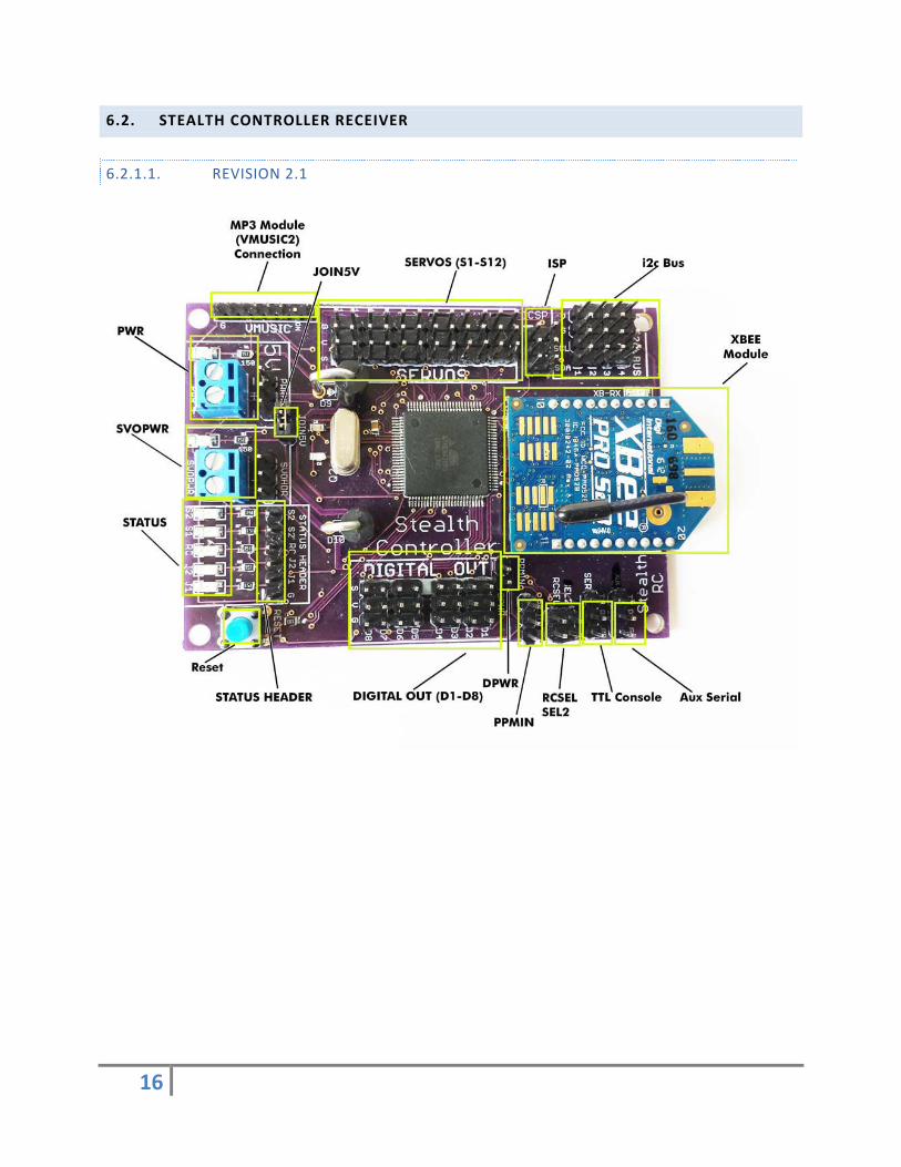
6.2. STEALTH CONTROLLER RECEIVER
6.2.1.1. REVISION 2.1

17
6.2.1.2. REVISION 2.2