Embed Size (px)
Citation preview
A
Project Report
On
Steady state simulation of Extractive
Distillation system using Aspen Plus
Submitted by
Pritam Kumar Bala
(Roll No: 111CH0595)
In partial fulfilment of the requirements for the degree in
Bachelor of Technology in Chemical Engineering
Under the guidance of
Dr. Pradip Chowdhury
Department of Chemical Engineering
National Institute of Technology
Rourkela
May 2015
i | P a g e
CERTIFICATE
This is certified that the work contained in the thesis entitled “Steady state simulation of
Extractive Distillation System using Aspen Plus” submitted by Pritam Kumar Bala
(111CH0595), has been carried out under my supervision and this work has not been
submitted elsewhere for a degree.
__________________
Date:
Place: (Thesis Supervisor)
Dr. Pradip Chowdhury
Assistant Professor,
Department of Chemical Engineering
NIT Rourkela
ii | P a g e
Acknowledgements
First and the foremost, I would like to offer my sincere gratitude to my thesis supervisor,
Dr. Pradip Chowdhury for his immense interest and enthusiasm on the project. His
technical prowess and vast knowledge on diverse fields left quite an impression on me. He
was always accessible and worked for hours with me. Although the journey was beset with
complexities but I always found his helping hand. He has been a constant source of
inspiration for me.
I am also thankful to all faculties and support staff of Department of Chemical
Engineering, National Institute of Technology Rourkela, for their constant help and extending
the departmental facilities for carrying out my project work.
I would like to extend my sincere thanks to my friends and colleagues. Last but not the least,
I wish to profoundly acknowledge my parents for their constant support.
____________________
(Pritam Kumar Bala)
111CH0595
iii | P a g e
ABSTRACT
In this project work, we report Aspen-plus simulation results of an azeotropic system viz.
isopropanol-water which forms a minimum boiling azeotrope. Because of its large scale
industrial application, separation of isopropanol-water mixture using the distillation process
gained prominence. In this work, two routes were followed leading to the simulation. The
first involved more conventional extractive distillation mechanism where Dimethyl sulfoxide
(DMSO) was used as an entrainer. A percentage purity of 99.9% was achieved w.r.t
isopropanol in the distillate or top product. However, a significant percentage of DMSO
remained in the bottom product. Since the recovery of DMSO was critical, another auxiliary
column was configured with the main scheme and a recovery of more than 99% was achieved
as the bottom product from the second column. Since this process involved two distillation
columns, a relatively more contemporary and modern distillation mechanism was resorted to
viz. divided wall distillation process. Improvisations were made in the flow sheet to mimic
divided wall distillation mechanism as Aspen-plus don’t have such specific simulator. The
results were comparable to what was achieved in extractive distillation process.
iv | P a g e
CONTENTS
PAGE NO.
Abstract III
List of Tables V
List of Figures VI
Notations and Abbreviations VII
CHAPTER 1: Introduction 1
1.1 Prelude 1
1.2 Applications 2
1.3 Uses of Isopropanol 2
1.4 Simulation multiplicity 3
1.5 Research objectives 4
CHAPTER 2: Literature Review 5
2.1 Theory of Extractive Distillation 6
2.1.1 Types of extractive distillation 7
2.2 Choice of solvent 7
CHAPTER 3: Steady State simulation (Results and Discussion) 8
3.1 Simulation Performed (Extractive) 8
3.2 Analysis 12
3.3 Simulation without Entrainer 15
CHAPTER 4: Divided Wall Distillation Column 21
4.1 Simulation Performed 23
4.2 Analysis 31
CHAPTER 5: Conclusion and Future Work 32
References 34
v | P a g e
List of Tables
3.1 Stream table of extractive distillation column 11
3.2 Stream table of extractive distillation column using design specs and vary 13
3.3 Stream table of normal distillation 15-16
3.4 Stream table of extractive distillation column along with recovery column 19
4.1 Stream table of Divided wall distillation column 26
vi | P a g e
List of figures
1.1 Extractive Distillation model 4
2.1 Configuration of extractive distillation 6
3.1 Steady state simulation of IPA-water mixture 8
3.2 Temperature profile of column B1 14
3.3 Liquid composition profile of column B1 14
3.4 Simulating model without entrainer 15
3.5 Run status of simulation 16
3.6 Txy plot of IPA-water 17
3.7 Complete setup to separate the three component 18
3.8 Temperature profile of column B2 20
3.9 Liquid composition profile of column B2 20
4.1 Divided wall distillation column 22
4.2 Arrangement used in simulation analogous to DWC 23
4.3 Normal completion of simulation 25
4.4 Temperature profile of MAIN column 27
4.5 Temperature profile of ENRICH column 27
4.6 Temperature profile of SIDE column 28
4.7 Temperature profile of STRIP column 28
4.8 Liquid composition profile of MAIN column 29
4.9 Liquid composition profile of ENRICH column 29
4.10 Liquid composition profile of SIDE column 30
4.11 Liquid composition profile of STRIP column 30
vii | P a g e
NOTATIONS AND ABBREVIATIONS
CPI = Chemical process Industries
DMSO = Dimethylsulfoxide
DWC = Divided wall distillation column
THF = Tetrahydrofuran
FE1 = Entrainer inlet stream
F1 = Feed inlet stream
B1 = Bottom product stream
D1 = Top product stream
ROM = Read only memory
IC = Integrated circuits
CD = Compact disk
LCD = Liquid crystal display
CPU = Central processing units
IPA = Isopropyl alcohol
NRTL = Non-random two liquid
LAB = Linear Alkyl Benzene
F = feed in DWC
B = Bottom product in DWC
D = Top product in DWC
S3 = Mid product from section 2 column
LNS2 = liquid product returning from section 2 column to stripping column in DWC
VNS1 = Vapor returning to enriching section from section 2 column in DWC
v = Vapor going into section 2 column in DWC
l = Liquid going into section 2 column in DWC
τ12
and τ21
= dimensionless interaction parameter
∆g12
and ∆g21
= interaction energy parameters
viii | P a g e
R = gas constant
T= Absolute Temperature
Uij = Energy between surfaces i and j
1 | P a g e
CHAPTER 1
INTRODUCTION
In this chapter we have discussed the fundamentals of distillation in general and extractive
distillation in particular. To separate azeotropic compositions formed between various
components constituting mixtures have been an area of research for several decades and
literatures on that are highlighted here. The background and the motivation behind carrying
out the study are summarized along with the specific objectives.
1.1 Prelude
Distillation is one of the most fundamental and sought after techniques prevalent in various
process industries. The success of distillation as a unit operation depends on the fundamental
factor called relative volatility. The higher the relative volatility, the easier the separation
would be. However, there arise many situations when the relative volatility between the
constituents of the mixture is quite adjacent to each other and hence the degree of difficulty to
separate them increases.
Azeotropes are constant boiling mixtures when vapour and liquid phase compositions are
equal and no separation by conventional distillation is possible beyond that point. The greater
the non-ideality in the mixture, the more probable is the chance of an azeotrope formation.
Ideal solutions obey Raoult’s law and non-ideal solutions deviate from that. There are two
possibilities: positive deviation or negative deviation. Generally, this deviation occurs large
because of the dissimilarity in the chemical configuration of the constituting species. This
differences lead to non-uniformity in the inter-molecular forces of attraction between them.
In positive from deviation, the partial predicted by the Raoult’s law is less than the practical
scenario, meaning higher escaping tendencies between the constituting molecules, leading to
a minimum boiling azeotrope, whereas, in case of negative deviation, the escaping tendencies
are less for the molecules, leading to a maximum boiling azeotrope [1-2]
. The occurrences of
minimum boiling azeotrpes are more common. Isopropanol-water system forms a minimum
boiling azeotropic system.
2 | P a g e
1.2 Application
Various methods have been developed and used industrially to separate azeotropic mixtures.
The methods are highlighted below:
Pressure swing distillation process
Azeotropic distillation with a light entrainer
Extractive distillation with a heavy entrainer (solvent)
Pervaportion
Some very popular and commonly occurring azeotropic mixtures are: isopropanol-water,
ethanol-water, tetrahydrofuran-water, n-butanol-water, acetone-methanol, isopentane-
methanol, acetic acid-water and acetone-chloroform from a wide list [2]
.
1.3 Uses of Isopropanol
Isopropyl alcohol has wide application. It is used as a solvent, as a chemical intermediate, in
medical field, in automotive and as anaesthesia. Major fraction of IPA is used as solvent and
in industrial applications. A tiny fraction is consumed for household use and in personal care
products. IPA is one of the major chemical in pharmaceutical industries due to its nature of
forming low toxicity of any residues. Few fractions are used as intermediate in various
industrial applications. Acetone is a gasoline additive, is one of the intermediate formed from
IPA.
Solvent
One of the important characteristics of IPA is that it can dissolve wide range of non-polar
products. Isopropanol few characteristics like its nontoxic and it evaporates quickly leaving
no residue makes it an ideal product to use as compared to other solvents like ethanol. Hence
major fractions of IPA produced are used as solvent. It is also used to clean delicate
electronic devices like ROM cartridges, CD, DVD, LCD screen. It is also used to remove
stains and removing paint.
Intermediate
Isopropyl alcohol is used in several methods as intermediate:-
3 | P a g e
It is used in esterification process to produce derivatives of isopropyl acetic acids
which are again used as solvents.
A herbicide and an ore floatation agent, sodium isopropylxanthate, is produced by
reacting IPA with sodium hydroxide and carbon disulphide.
Titanium isopropoxide is formed when IPA reacts with Titanium tetrachloride.
Aluminium isopropoxide is produced when IPA reacts with aluminium.
Medical
IPA is widely used as sanitizing cushions having 60–70% arrangement of IPA in water. It is
also utilized as a hand sanitizer and as a water-drying guide for the antipathy of otitis externa.
This is also known as swimming ear.
Early uses as an anaesthetic
Previously Isopropyl alcohol was used as anaesthesia. But due to its numerous negative
disadvantages its use as anaesthesia was stopped. IPA can be utilized as a dissolvable or as a
sedative by breathing in the vapour or orally. Its use was soon stopped due to various side
effects including respiratory disturbance, inner drying, and visual and auditory issues.
Automotive
IPA is a critical altering in "gas dryer" fuel included substances. In discriminating sums,
water is an issue in fuel tanks, as it partitions from the gas, and can harden in the supply lines
at chilly temperatures. Alcohol does not remove water from fuel; rather, the alcohol
solubilizes water in gas. At the point when dissolvable, water does not speak to the same
danger as insoluble water, as it will no more gather in the supply lines and stop. Isopropyl
liquor is habitually sold in vaporized jugs as a win shield de-icer. IPA is also used to oust
brake fluid takes after from water controlled halting computerizations, leads to poor braking.
1.4 Simulation multiplicity
Most of the equations involved in designing distillation columns viz. component mass
balances, energy balances, vapour-liquid phase equilibrium relationships, column hydraulic
equations are non-linear. Since non-linear equations have multiple roots, convergence of
solution is always going to be difficult. It means that we may have multiple results for the
4 | P a g e
same set of inputs also known as ‘output multiplicity’ [2]
. This adds to the already existing
complexity in simulating distillation columns. Therefore, in Aspen-plus simulation
methodology, this particular aspect of convergence is always going to be a key issue.
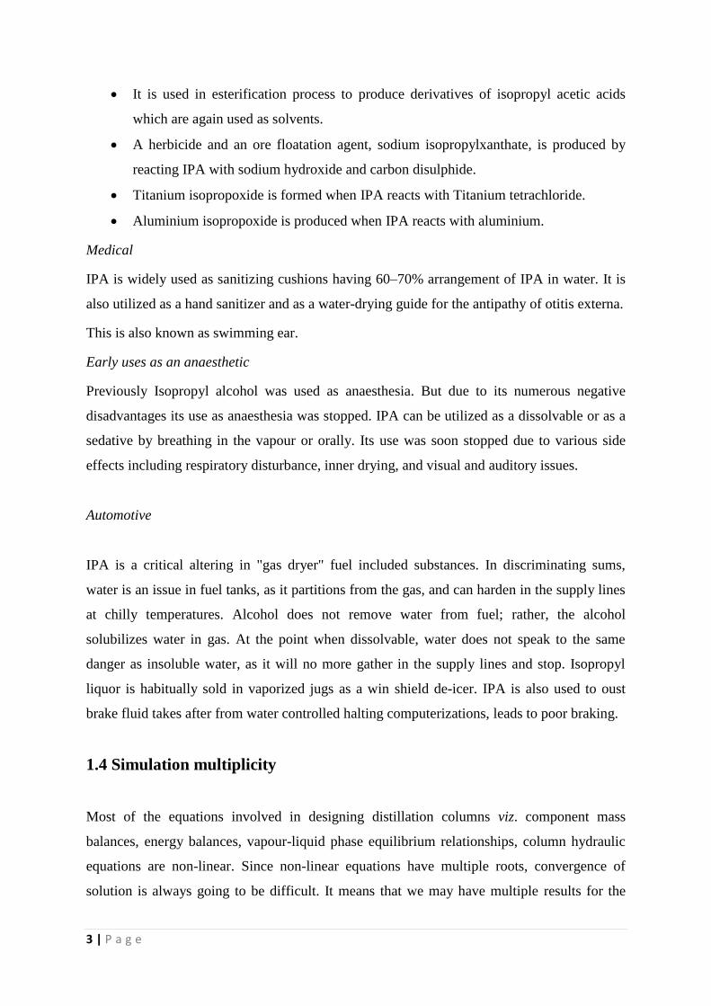
A simple schematic of extractive distillation simulation configuration is shown below:
Fig-1.1 Schematic of an Extractive Distillation process
FE1 is entrainer feed. F1 is fresh feed of azeotrope. B1 is bottom product and D1 is distillate.
Further discussion will be carried out later.
1.5 Research Objectives
To study the functioning of anextractive distillation column in steady state with
special emphasis on a minimum boiling azeotropic mixture (isopropanol-water)
where isopropanol is extracted using a suitable entrainer viz. dimethyl sulfoxide
(DMSO).
To study the optimization of the number of trays, feed plate, entrainer plate and purity
of distillate obtained by varying the process variables like reflux ratio and distillate
rate.
To study the recovery of entrainer from water using another distillation column or
extracting all the three in a single distillation column with special emphasis on a
divided wall distillation system.
5 | P a g e
CHAPTER-2
LITERATURE REVIEW
A distillation column has two sections namely stripping section and rectifying section. In
order to separate three component mixture into pure products two distillation columns are
required. So in total four sections are required to separate three component mixture [3]
. Each
section of the column namely stripping sections and rectifying section has a reboiler and a
condenser respectively. Getting output with minimum use of energy has been a new trend in
production line. This demand is achieved by dividing wall distillation column (DWC).
Separation of three components is done in single column rather than in two columns as done
in conventional method. Major advantage in DWC is by avoiding remixing problem which
was quite an issue in conventional distillation methods. Hence DWC is an energy efficient
method and an alternative to conventional method [4]
. In DWC a wall in between the column
separates the product zone and side stream zone and increase the efficiency of DWC as
compared to the conventional one [5]
. Dividing wall inside the column plays a crucial role in
product purity. In order to have high purity of product insulation of this wall is properly done
to avoid heat transfer through it. In general dividing wall is placed in the middle but the
position can be varied in accordance to medium boiling component. This change in placing
the wall is seen when medium boiling component is small as compared to overhead and
bottom product obtained [6]
. Few assumptions were taken before DWC model was prepared
viz. pressure maintained in column is constant with no dynamic vapor flow, energy balance
and change in enthalpy is neglected. Various control strategies were compared using this
model [7]
. Another assumption is for ideal components where mass and heat transfer takes
place between its liquid and vapor phases [8]
.
In this paper minimum boiling azeotrope (Isopropanol- water) is separated using an entrainer
DMSO using both conventional method of distillation and dividing wall distillation column
(DWC). Aspen plus software provides various simulation models so that optimum input
variables can be calculated before starting a process in any production plant. In Aspen plus
6 | P a g e
V8.4 divided wall distillation column is not provided hence a mimic model has been taken to
get an optimum result which is exact replica of dividing wall distillation column in terms of
functioning.
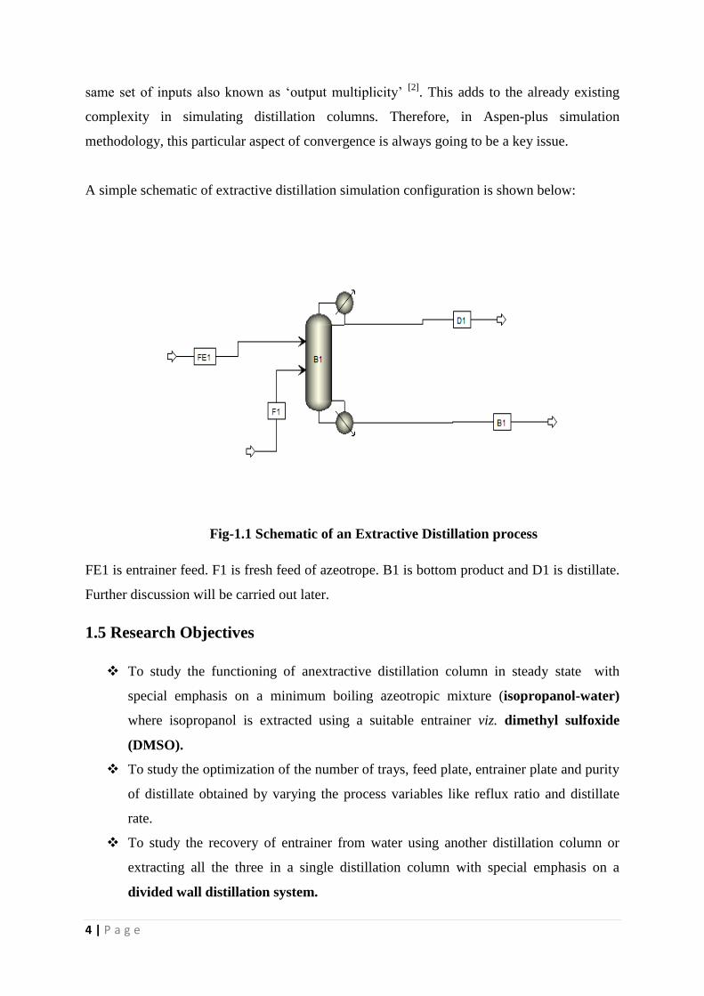
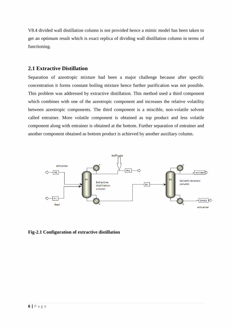
2.1 Extractive Distillation
Separation of azeotropic mixture had been a major challenge because after specific
concentration it forms constant boiling mixture hence further purification was not possible.
This problem was addressed by extractive distillation. This method used a third component
which combines with one of the azeotropic component and increases the relative volatility
between azeotropic components. The third component is a miscible, non-volatile solvent
called entrainer. More volatile component is obtained as top product and less volatile
component along with entrainer is obtained at the bottom. Further separation of entrainer and
another component obtained as bottom product is achieved by another auxiliary column.
Fig-2.1 Configuration of extractive distillation
7 | P a g e
2.1.1 Types of extractive distillation
Extractive distillation process can be split into three important categories:
Separation of minimum boiling azeotropes
Separation of maximum boiling azeotropes
The separation of low relative volatility non-azeotropic mixtures.
For separating binary mixtures into pure components.
In extractive distillation, importantly, a solvent is purposely added two widen the boiling
point differences of the constituting species of the mixture or to avoid forming any
azeotropes. So selection of a proper solvent is always remained very important in the overall
success of the process.
2.2 Choice of Solvent
A solvent to be used as an entrainer, preferably, should have the following salient features or
characteristics:
•Relative volatility of the key component should be enhanced.
•Ratio of solvent to non-solvent should be quite less.
• Easily soluble with feed components and do not form any two phase with it.
•Easily separable from the bottom product.
•Inexpensive and readily available.
•Stable at the operating temperature of the distillation column.
•Non-reactive with the components in the feed mixture.
•Low latent heats.
•Non-corrosive and non-toxic.
8 | P a g e
CHAPTER 3
STEADY STATE SIMULATION
(Results and Discussion)
3.1 Simulation performed [2]
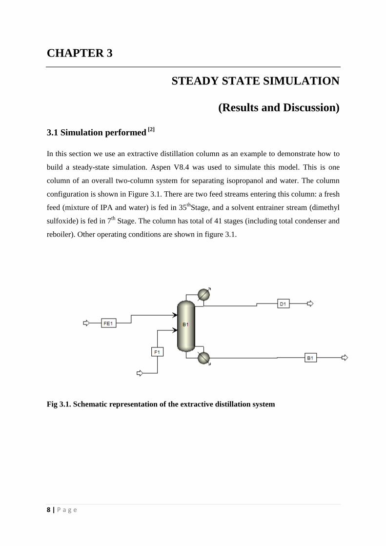
In this section we use an extractive distillation column as an example to demonstrate how to
build a steady-state simulation. Aspen V8.4 was used to simulate this model. This is one
column of an overall two-column system for separating isopropanol and water. The column
configuration is shown in Figure 3.1. There are two feed streams entering this column: a fresh
feed (mixture of IPA and water) is fed in 35th
Stage, and a solvent entrainer stream (dimethyl
sulfoxide) is fed in 7th
Stage. The column has total of 41 stages (including total condenser and
reboiler). Other operating conditions are shown in figure 3.1.
Fig 3.1. Schematic representation of the extractive distillation system
9 | P a g e
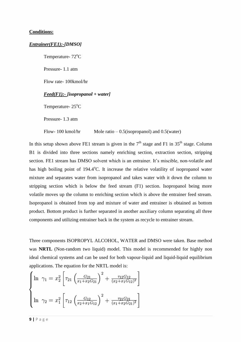
Conditions:
Entrainer(FE1):-[DMSO]
Temperature- 72oC
Pressure- 1.1 atm
Flow rate- 100kmol/hr
Feed(F1):- [isopropanol + water]
Temperature- 25oC
Pressure- 1.3 atm
Flow- 100 kmol/hr Mole ratio – 0.5(isopropanol) and 0.5(water)
In this setup shown above FE1 stream is given in the 7th
stage and F1 in 35th
stage. Column
B1 is divided into three sections namely enriching section, extraction section, stripping
section. FE1 stream has DMSO solvent which is an entrainer. It’s miscible, non-volatile and
has high boiling point of 194.4oC. It increase the relative volatility of isopropanol water
mixture and separates water from isopropanol and takes water with it down the column to
stripping section which is below the feed stream (F1) section. Isopropanol being more
volatile moves up the column to enriching section which is above the entrainer feed stream.
Isopropanol is obtained from top and mixture of water and entrainer is obtained as bottom
product. Bottom product is further separated in another auxiliary column separating all three
components and utilizing entrainer back in the system as recycle to entrainer stream.
Three components ISOPROPYL ALCOHOL, WATER and DMSO were taken. Base method
was NRTL (Non-random two liquid) model. This model is recommended for highly non
ideal chemical systems and can be used for both vapour-liquid and liquid-liquid equilibrium
applications. The equation for the NRTL model is:
10 | P a g e
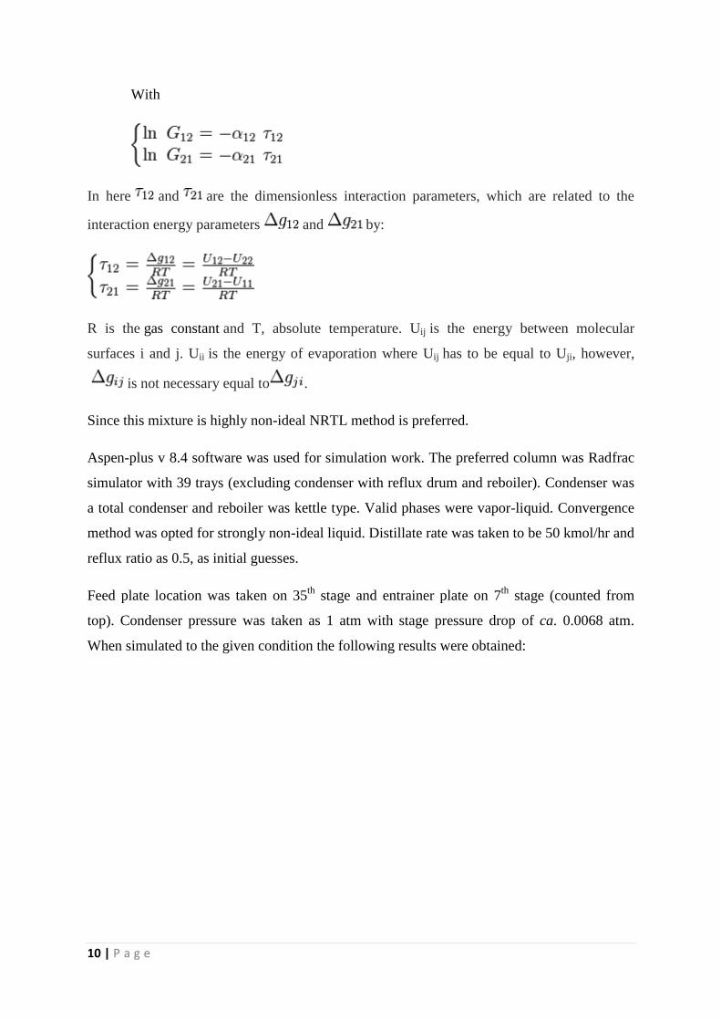
With
In here and are the dimensionless interaction parameters, which are related to the
interaction energy parameters and by:
R is the gas constant and T, absolute temperature. Uij is the energy between molecular
surfaces i and j. Uii is the energy of evaporation where Uij has to be equal to Uji, however,
is not necessary equal to .
Since this mixture is highly non-ideal NRTL method is preferred.
Aspen-plus v 8.4 software was used for simulation work. The preferred column was Radfrac
simulator with 39 trays (excluding condenser with reflux drum and reboiler). Condenser was
a total condenser and reboiler was kettle type. Valid phases were vapor-liquid. Convergence
method was opted for strongly non-ideal liquid. Distillate rate was taken to be 50 kmol/hr and
reflux ratio as 0.5, as initial guesses.
Feed plate location was taken on 35th
stage and entrainer plate on 7th
stage (counted from
top). Condenser pressure was taken as 1 atm with stage pressure drop of ca. 0.0068 atm.
When simulated to the given condition the following results were obtained:
11 | P a g e
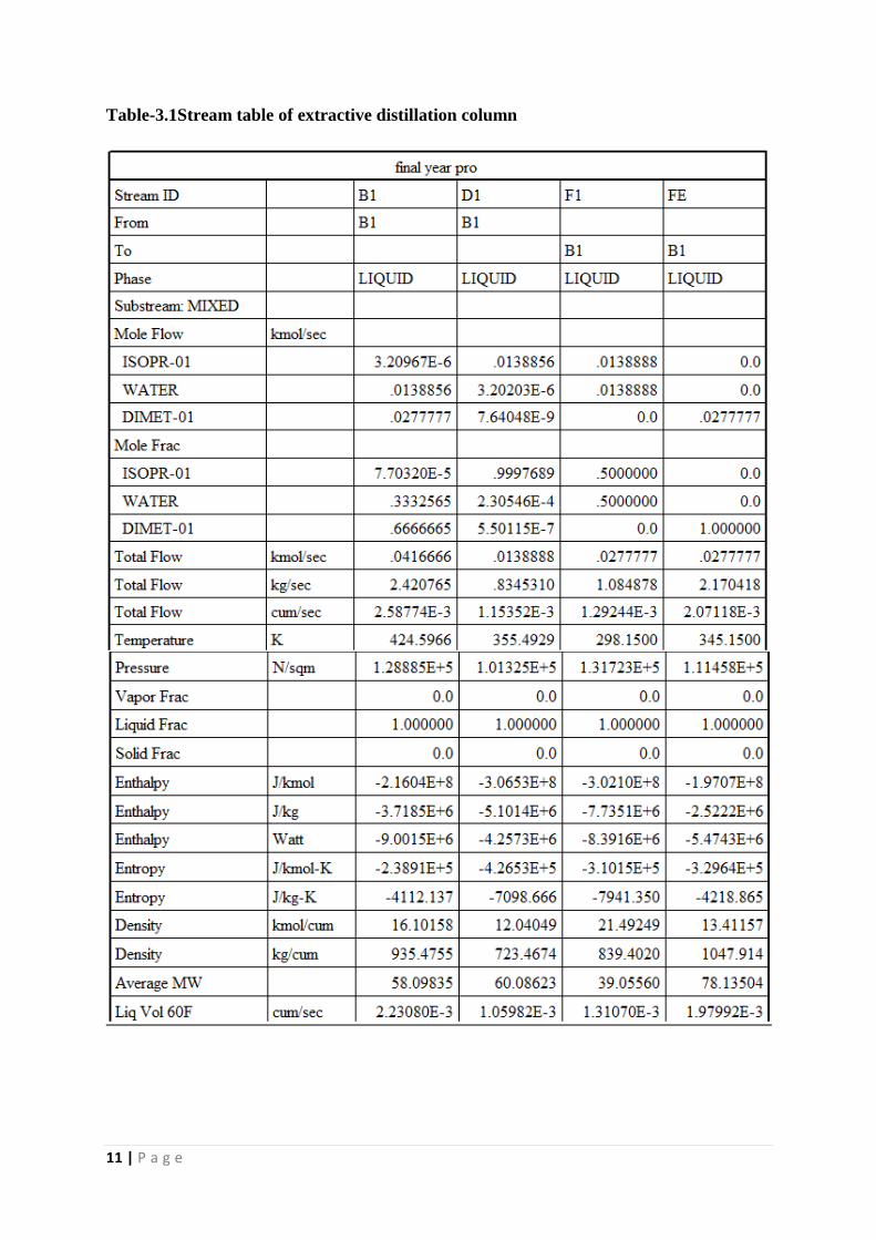
Table-3.1Stream table of extractive distillation column
12 | P a g e
Here we are getting mole fraction of isopropanol 0.9997689. In order to increase the purity
we used design specs and vary function.
3.2 Analysis
In design specs option type taken as mole purity with target as 0.9999999 with component as
isopropanol and stream is DI. In vary option type taken as distillate rate with lower bound
0.01 kmol/sec and upper bound as 0.02 kmol/sec then simulation run which completed in 18
iterations. Taking second design spec as mole ratio of IPA and IPA+ water as 0.001 from
bottom (B1). Vary taken as reflux ratio ranging 0.1 to 1.0. It converges in 16 iterations.
Reflux ratio came 0.6895 and distillate flow rate as 50.007 kmol/hr. The results we are
getting are quite encouraging as we are getting a purity of 0.9999 isopropanol from top as
distillate.
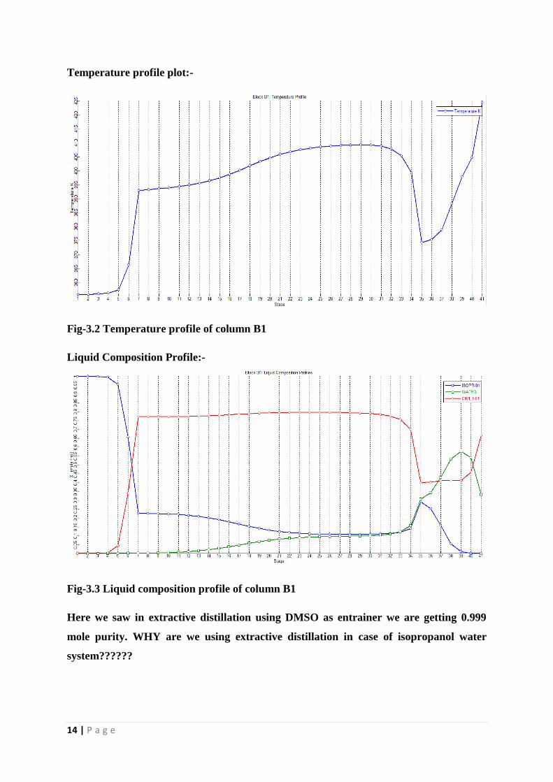
In the temperature profile plot given below there is a sharp rise near 7th
plate. This change is
observed as the entrainer is given into the column at this stage which is at higher temperature
as compared to column temperature. Then there is a general rise in curve as temperature
down the column increases due to the presence of reboiler. But sharp fall near the 35th
plate is
observed because feed which is at 298.15 K in given into column which brings down the
temperature of the column. After 35th
column general rise in curve is observed.
In liquid composition profile IPA mole fraction goes on increasing to the top of the column as
its more volatile as compared to other two components. Sharp rise is observed after 7th
plate
as DMSO (entrainer ) is introduced. Mole fraction of IPA is nearly 0 at 41st stage. Likewise
water mole fraction increases after 35th
plate as feed first comes in contact with DMSO there
and DMSO separates water from feed.
13 | P a g e
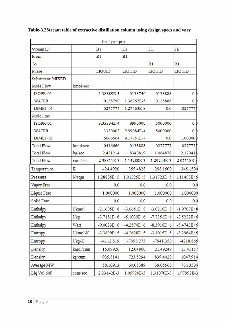
Table-3.2Stream table of extractive distillation column using design specs and vary
14 | P a g e
Temperature profile plot:-
Fig-3.2 Temperature profile of column B1
Liquid Composition Profile:-
Fig-3.3 Liquid composition profile of column B1
Here we saw in extractive distillation using DMSO as entrainer we are getting 0.999
mole purity. WHY are we using extractive distillation in case of isopropanol water
system??????
15 | P a g e
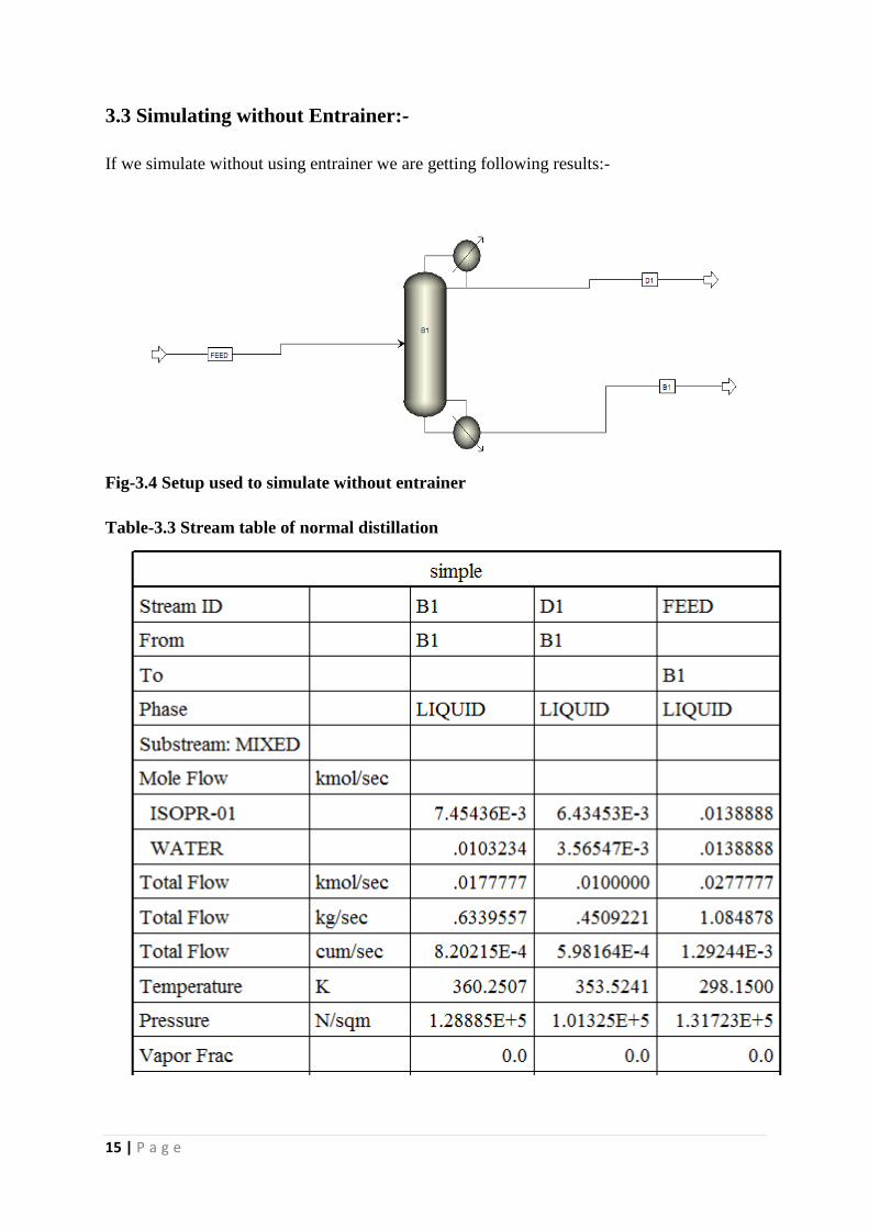
3.3 Simulating without Entrainer:-
If we simulate without using entrainer we are getting following results:-
Fig-3.4 Setup used to simulate without entrainer
Table-3.3 Stream table of normal distillation
16 | P a g e
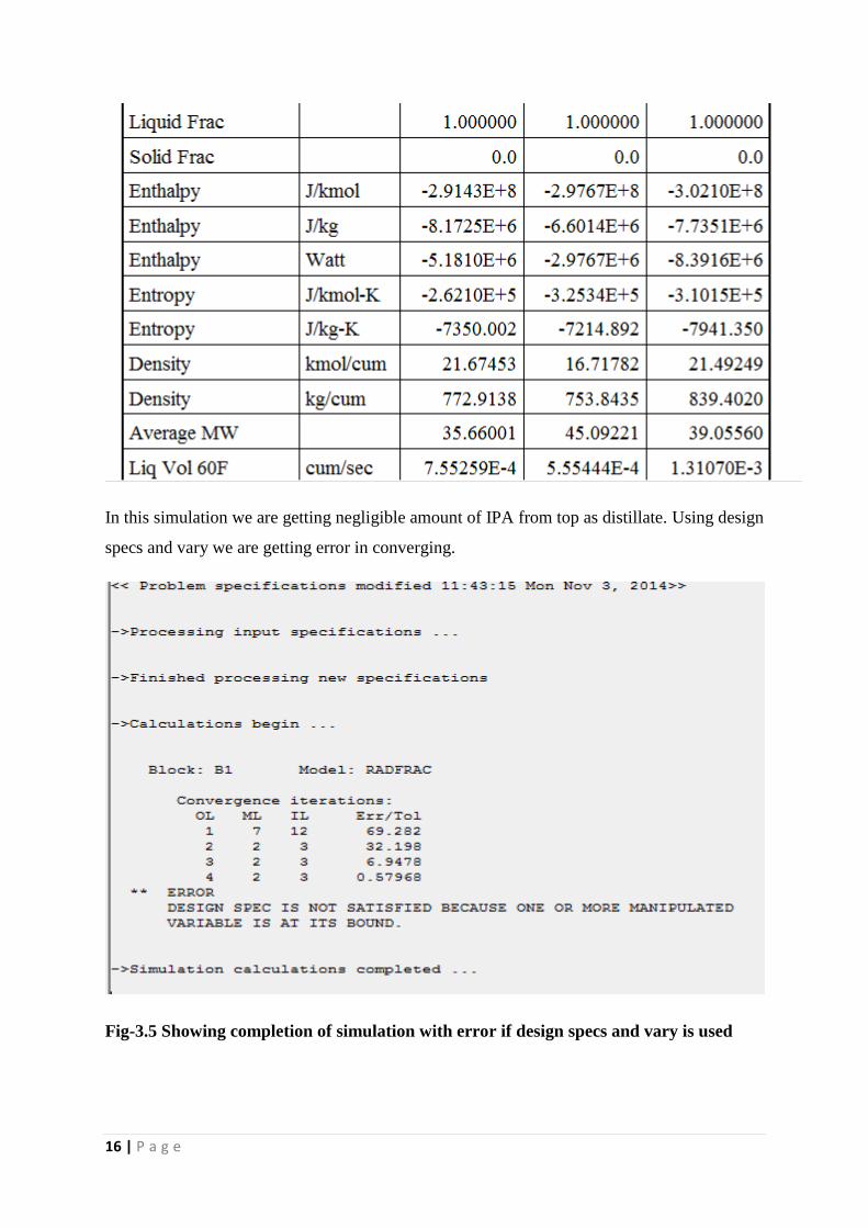
In this simulation we are getting negligible amount of IPA from top as distillate. Using design
specs and vary we are getting error in converging.
Fig-3.5 Showing completion of simulation with error if design specs and vary is used
17 | P a g e
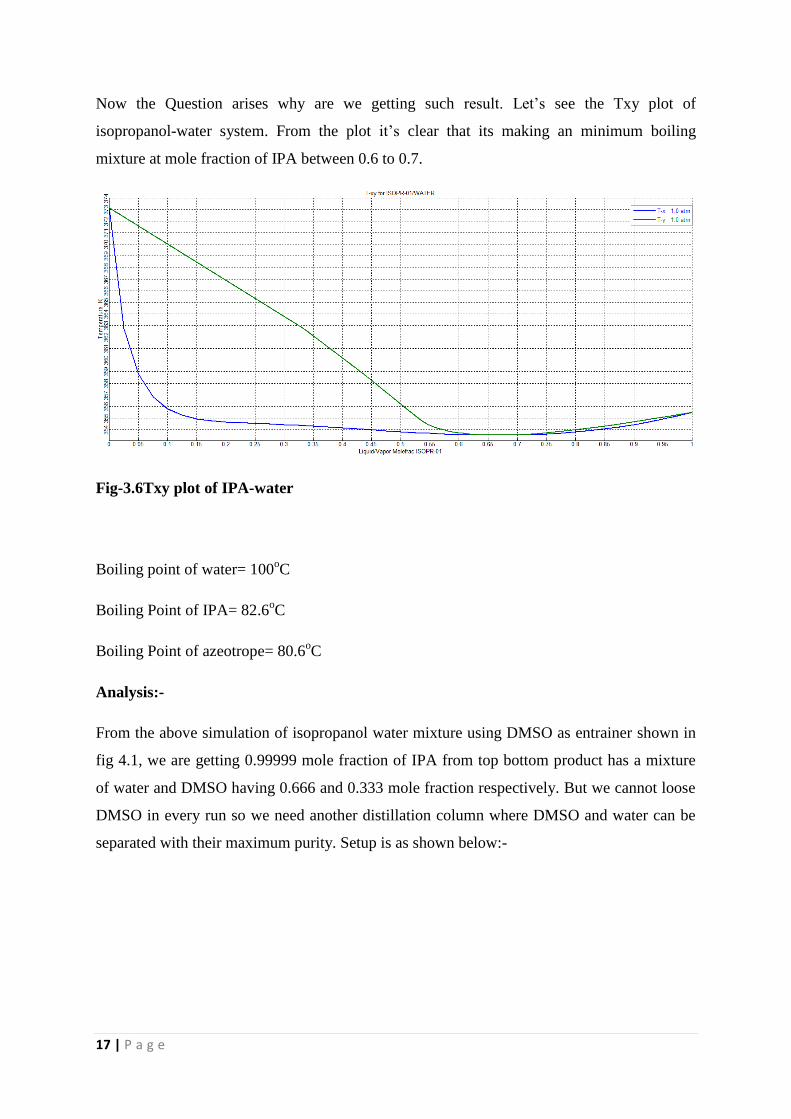
Now the Question arises why are we getting such result. Let’s see the Txy plot of
isopropanol-water system. From the plot it’s clear that its making an minimum boiling
mixture at mole fraction of IPA between 0.6 to 0.7.
Fig-3.6Txy plot of IPA-water
Boiling point of water= 100oC
Boiling Point of IPA= 82.6oC
Boiling Point of azeotrope= 80.6oC
Analysis:-
From the above simulation of isopropanol water mixture using DMSO as entrainer shown in
fig 4.1, we are getting 0.99999 mole fraction of IPA from top bottom product has a mixture
of water and DMSO having 0.666 and 0.333 mole fraction respectively. But we cannot loose
DMSO in every run so we need another distillation column where DMSO and water can be
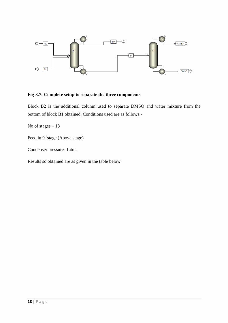
separated with their maximum purity. Setup is as shown below:-
18 | P a g e
Fig-3.7: Complete setup to separate the three components
Block B2 is the additional column used to separate DMSO and water mixture from the
bottom of block B1 obtained. Conditions used are as follows:-
No of stages – 18
Feed in 9th
stage (Above stage)
Condenser pressure- 1atm.
Results so obtained are as given in the table below
19 | P a g e
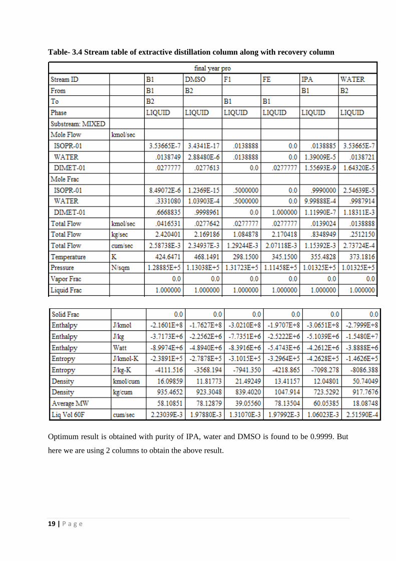
Table- 3.4 Stream table of extractive distillation column along with recovery column
Optimum result is obtained with purity of IPA, water and DMSO is found to be 0.9999. But
here we are using 2 columns to obtain the above result.
20 | P a g e
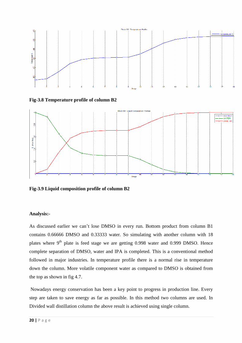
Fig-3.8 Temperature profile of column B2
Fig-3.9 Liquid composition profile of column B2
Analysis:-
As discussed earlier we can’t lose DMSO in every run. Bottom product from column B1
contains 0.66666 DMSO and 0.33333 water. So simulating with another column with 18
plates where 9th
plate is feed stage we are getting 0.998 water and 0.999 DMSO. Hence
complete separation of DMSO, water and IPA is completed. This is a conventional method
followed in major industries. In temperature profile there is a normal rise in temperature
down the column. More volatile component water as compared to DMSO is obtained from
the top as shown in fig 4.7.
Nowadays energy conservation has been a key point to progress in production line. Every
step are taken to save energy as far as possible. In this method two columns are used. In
Divided wall distillation column the above result is achieved using single column.
21 | P a g e
CHAPTER 4
DIVIDED WALL DITILLATION COLUMN
In recent years, more energy efficient distillation columns have been designed such as the
Petlyuk column and divided wall column (DWC) which have greatly reduced the reboiler
heat duty for a given separation.
The DWC is a configuration of two basic thermally coupled distillation sections put into one
section by creating a vertical divider isolating the centre in two sections that act as the pre or
post-fractionator and the main column. Thermodynamically, a DWC can be considered as an
equivalent of the Petlyuk column [9]
. The only difference between a DWC and a Petlyuk
column lies in the stage/plate at which the liquid splitting and vapour return take place. The
DWC has compact design; require less space and has higher vitality productivity when
compared with a traditional distillation column. Here, an azeotropic mixture or mixture
having multiple components can be separated in one column. In case of an azeotropic
mixture, an entrainer is used to separate the mixture where both components along with the
entrainer are separated individually from a single column. This is a new method taking shape
now-a-days accepted widely across industries. DWC is widely used in linear alkyl benzene
(LAB) forming industries. In LAB production, when the output is about 2.6 MT/yr, DWC
saves 9% of total energy when compared with conventional distillation columns. A sum of
around $12.8 million is saved per year on installing DWC rather than using conventional
distillation column [10]
.
22 | P a g e
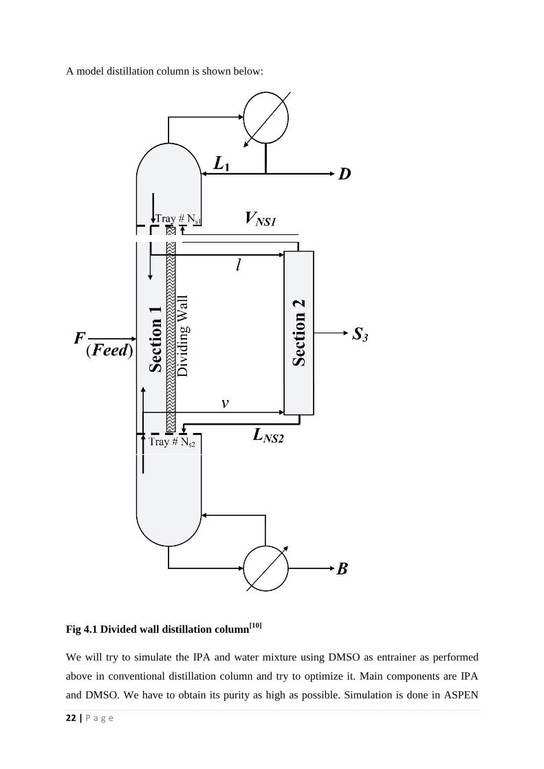
A model distillation column is shown below:
Fig 4.1 Divided wall distillation column[10]
We will try to simulate the IPA and water mixture using DMSO as entrainer as performed
above in conventional distillation column and try to optimize it. Main components are IPA
and DMSO. We have to obtain its purity as high as possible. Simulation is done in ASPEN
23 | P a g e
PLUS 11.1 and V8.04 software. Direct distillation column is not available in column section.
Hence we are using 4 columns which will be analogous to DWC. Those four columns include
two absorption columns, one rectifying column and one stripping column.One mixer and one
splitter is used.
4.1 Simulation performed
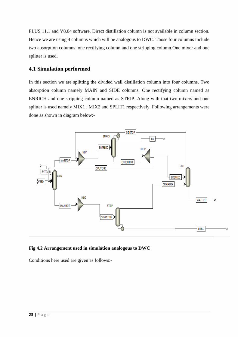
In this section we are splitting the divided wall distillation column into four columns. Two
absorption column namely MAIN and SIDE columns. One rectifying column named as
ENRICH and one stripping column named as STRIP. Along with that two mixers and one
splitter is used namely MIX1 , MIX2 and SPLIT1 respectively. Following arrangements were
done as shown in diagram below:-
Fig 4.2 Arrangement used in simulation analogous to DWC
Conditions here used are given as follows:-
24 | P a g e
MAIN COLUMN
Feed line is given to 15th
plate to MAIN column which consist of 0.5 mole fraction of IPA
and water respectively. Entrainer used is DMSO which is given to MAIN column through
ENTRAIN line both feed and entrainer given as 100kmol/hr. Number of plates taken as 29.
Feed pressure is taken as 1.3 atm where as entrainer line pressure is taken as 1.1 atm.
Condenser pressure is 1 atm. Here condenser is none and reboiler used is kettle.
ENRICH COLUMN
Here column taken is a rectifying column. All the top products from MAIN column and SIDE
column moves into it ENRICH column at 9th
stage (onstage). Number of stages used is 9.
Further condenser pressure is 1 atm. Reboiler is none. Distillate rate is 50 kmol/hr.
SPLIT1
This is a major section of the process as alteration at this point i.e split ratio results in change
in concentration of final product. Split ratio is taken to be 0.9 to SIDE column and 0.1 back to
main column. Reducing the value from 0.9 results in decrease in concentration of water from
SIDE column. Further increase in split ratio from 0.9 results in decrease in IPA
concentration.
SIDE COLUMN
Column here taken is an absorption column. Bottom product from ENRICH column is splited
in SPLIT1 out of which 0.9 split ratio is sent into SIDE column in 1st stage(onstage) . It has
total 29 stages. Condenser pressure maintained is 1atm. Condenser and reboiler is taken as
none. Water is taken out from the bottom of the column. Top product from STRIP column is
fed into 29th
stage (onstage) and no splitter is used here.
STRIP COLUMN
This column is used for stripping purpose. Stripping column is used as almost all water along
with DMSO is move down to this column and is fed in 1stplate (onstage). Condenser here is
none and reboiler is kettle. Boil up ratio is used. It’s taken as 0.9. Decrease in boilup ratio
lead to decrease in DMSO concentration as product whereas further increase in boilup ratio
results in no change in DMSO concentration. Hence for optimum condition 0.9 is taken.
25 | P a g e
MIX1 , MIX2, SPLIT1
Mixers and splitters are used to amplify the result obtained here as in real DWC proper
mixing and splitting is performed. From the above explanations MIX1 and SPLIT1 function
is known. MIX2 is not necessary but taken only for proper mixing it can also be removed and
required results can be obtained.
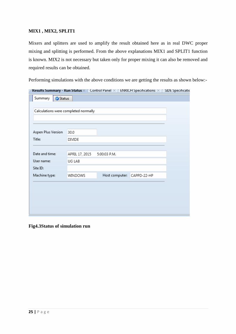
Performing simulations with the above conditions we are getting the results as shown below:-
Fig4.3Status of simulation run
26 | P a g e
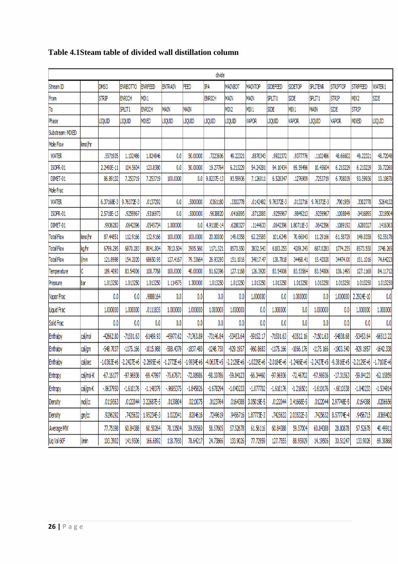
Table 4.1Steam table of divided wall distillation column
27 | P a g e
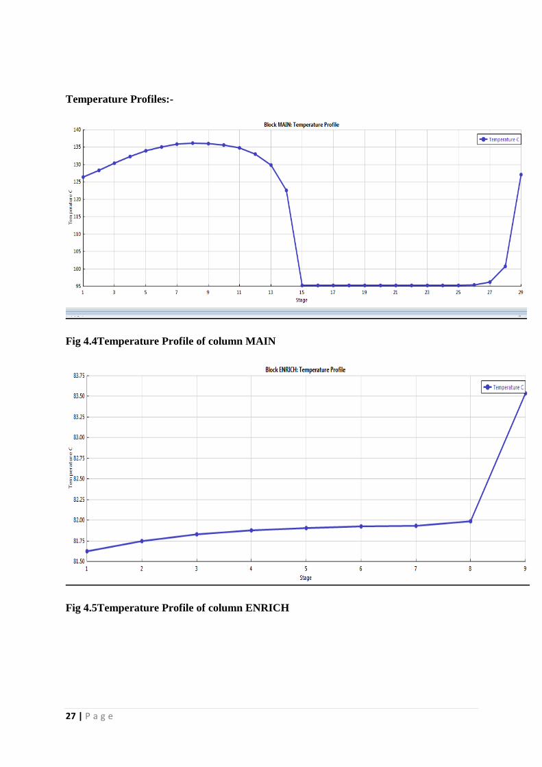
Temperature Profiles:-
Fig 4.4Temperature Profile of column MAIN
Fig 4.5Temperature Profile of column ENRICH
28 | P a g e
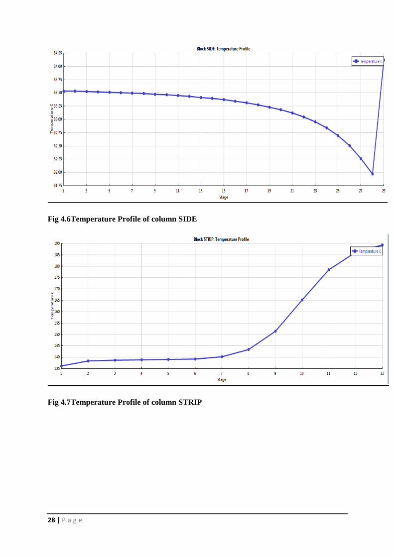
Fig 4.6Temperature Profile of column SIDE
Fig 4.7Temperature Profile of column STRIP
29 | P a g e
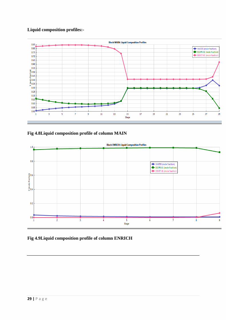
Liquid composition profiles:-
Fig 4.8Liquid composition profile of column MAIN
Fig 4.9Liquid composition profile of column ENRICH
30 | P a g e
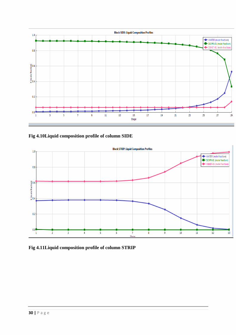
Fig 4.10Liquid composition profile of column SIDE
Fig 4.11Liquid composition profile of column STRIP
31 | P a g e
4.2 Analysis
In this entire setup model used is RADFRAC distillation column. This is the most suitable
option available since it provides flexibility in reboiler and condenser conditions. In this
model we can take condenser and reboiler as none. In addition to that vaporization or
murphee efficiency can be specified in stage or component basis. This model is user friendly
in various options and provides a wide range of flexibility. Heat curves of reboiler and
condenser can easily be plotted using this model.The liquid split factor in the dividing wall
column decides how much quantity of the liquid will enter the SIDE column from the
rectifying section. Liquid from the bottom of rectifying section is rich in water and DMSO
component which are to be separated in SIDE column hence major portion of liquid is sent to
SIDE column (0.9).
A splitter was also used in between stripper column and SIDE column but water mole
fraction was coming to be 0.0104 which is very minimal. At that time water was withdrawn
from 28th
plate. On removing the splitter and sending the entire top product of stripping
column into SIDE column gives water mole fraction to be 0.555 which is nearly equal to feed
proportion of 0.5 hence can be used as recycled product. Water line constitutes 0.52 water,
0.33 IPA and 0.15 DMSO. Upon modification we are getting 0.9638 IPA from top 0.9936
from bottom DMSO which are the major components in this entire simulation. In stripping
section boil-up ratio is taken to be 0.9.
32 | P a g e
CHAPTER 5
CONCLUSIONS AND FUTURE WORKS
We have successfully simulated an extractive as well as divided wall distillation system using
Aspen-plus for separating isopropanol-water mixture using dimethyl sulfoxide (DMSO) as an
entrainer. The extractive distillation system required 2 distillation column assemblies for
achieving desired degrees of purity whereas in divided wall system, the target values were
achieved in a single assembly, reducing the requirements of additional auxiliaries. The salient
outcomes of this work are outlined below:
(a) The total number of theoretical plates required for achieving 99% and higher mole purity
w.r.t isopropanol (IPA) was found to be 41 (out of which 39 were trays and 2 were for
reboiler and condenser with reflux drum). The optimum feed and entrainer plate was located
at 35th
and 7th
stage respectively (counted from top down). The values of the manipulated
variables viz. distillate flow rate and reflux ratio were ca. 50 kmol/h and 0.6895 respectively
for achieving 99% and higher mole purity of the distillate product (isopropanol).
(b) A significant percentage of DMSO remained in the bottom product of the first column of
the extractive system which was successfully recovered (>99%) as a bottom product from the
auxiliary column of the assembly.
(c) Since this process involved two distillation columns, a relatively more contemporary and
modern distillation mechanism was resorted to viz. divided wall distillation process.
Improvisations were made in the flow sheet to mimic divided wall distillation mechanism as
Aspen-plus don’t have such specific simulator. The results were comparable to what was
achieved in extractive distillation process. The simulation results predicted mole purities of
0.9638 (isopropanol), 0.993 (DMSO) and 0.52 (water) respectively.
33 | P a g e
The future scope of this work can be the following:
(a) Detailed investigation of similar azeotropic mixtures using extractive distillation vis-à-vis
divided wall distillation systems.
(b) Studies on performances of several other entrainers on isopropanol-water mixture.
(c) Dynamic simulation study of isopropanol-water system by introducing controlling
mechanisms.
34 | P a g e
REFERENCES
[1] Segovia-Hernandez. J.G.Extractive Dividing Wall Column: Design and Optimization.
Ind.Eng.Chem.Res.,49,3672-3688(2010)
[2]Luyben,William L, I-LungChien. Design and control of distillation systems for separating
azeotropes.1-94(2010)
[3]Stupin W. J., Lockhart, F. J. Thermally coupled distillation-a case history.Chem. Eng.
Program, 68, 71-72(1972)
[4]Serra, M., Espuna, A. &Puigjaner, L. Control and optimization of the divided
wall column. Chemical Engineering and Processing, 38, 549-562 (1999)
[5]Hernandez S. ,Gabriel S. H. Thermodynamically equivalent distillation
schemes to the Petlyuk column for ternary mixtures. Energy, 31, 2176-2183 (2006)
[6]Asprion N. ,Kaibel G. Dividing wall columns: Fundamentals and recent
Advances. Chemical Engineering and Processing: Process Intensification, 49, 139-146 (2010)
[7]VanDiggelen R.C., Kiss A.A., Heemink A.W. Comparison of Control
Strategies for Dividing-Wall Columns. Industrial& Engineering Chemistry Research,
49, 288-307 (2010)
[8]Hiller C., Buck C., Ehlers C., Fieg G. Non-equilibrium stage modelling of
Dividing wall columns and experimental validation. Heat & Mass Transfer, 46, 1209–
1220 (2010)
[9] PetlyukPlatonovV. M., SlavinskiiD. M., Int. Chem. Eng. J.5.555–561(1965)
[10]Sangal V.K., KumarVineet, MishraIndra Mani.Chemical Industry & Chemical
EngineerinGQuarterly.19 (1) 107−119 (2013)