Embed Size (px)
Citation preview
Status of very high priority beam tuning software
Special ATF2 project meeting, Korea, 1st October 2008
Cécile Rimbault, on behalf of High Priority task leaders

Status of very high priority beam tuning software
• Coupling measurement and correction in EXT line CR, P. Bambade, JJ, S.Kuroda, T.Okugi, G. White, M. Woodley
• Dispersion measurement and correction in EXT line J.Jones, S. Molloy, TO, MW
• EXT orbit correction Y. Renier, PB, KK, J. Resta-Lopez, AS, GW
• FFS orbit correction A. Scarfe, P. Burrows, JRL, YR, GW
• Beta matching K. Kubo, M. Pivi

Coupling: measurement Methods
• Goal: correct coupling upstream of the final focus line with available skew quads in EXT (2 then 4)
• Possible sources of coupling: DR, QM7 and other bending magnets, QS1X & QS2X used to correct the dispersion, roll quad errors.
• Measurement of coupling = measurement of the non diagonal components of sigma matrix via beam size measurements (x, y, 10 degrees)
• Multi (≥3) wire scanner positions method theor. 10 sigma matrix elements.but too large error on , need to constraint the fit and need a good phase advance between wire scanners.
• Quadrupole and 2 skew quadrupole scan method wire scanners. Normal
+Skew scans in x but experimentaly flat thus 10° is needed +Skew scans in y
+Skew scans in 10°

Coupling: correction procedures• Use simulation to reproduce experimental measurements, assuming different sources of coupling (separately or together), and scan the 2 skew quads to find the strength couple which minimize the projected vertical emittance. Then apply it experimentally,and measure again coupling and vertical emittance (it was aimed in ATF spring 08 shifts)
• need to be automatized (Integration to flight simulator ) (Planned). • study if two skews are enough. (Priority)• study the benefit of a third skew quad and find the better position (Priority).
• Experimental method to minimize vertical emittance measured at 4 wire scanners, based on successive iterations.
• Search for a more direct coupling correction calculation with 3 or 4 skew quads using optics code, reconstructing the 4D sigma matrix and fitting it to be block diagonal Need to study the feasibility of this with MAD, SAD, MADX...
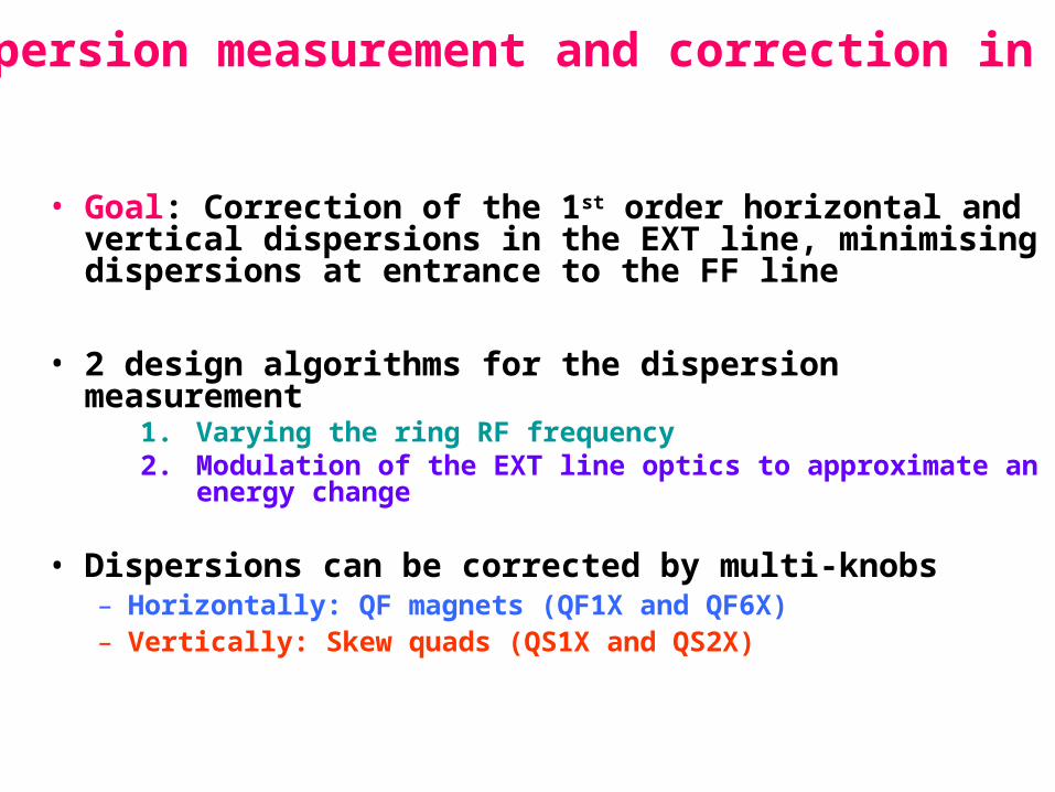
Dispersion measurement and correction in EXT
• Goal: Correction of the 1st order horizontal and vertical dispersions in the EXT line, minimising dispersions at entrance to the FF line
• 2 design algorithms for the dispersion measurement1. Varying the ring RF frequency2. Modulation of the EXT line optics to approximate an energy
change
• Dispersions can be corrected by multi-knobs– Horizontally: QF magnets (QF1X and QF6X)– Vertically: Skew quads (QS1X and QS2X)

Example: Simulation Procedure (100 seeds)
• apply standard errors (EXT only)
• steer flat (EXT only)
• launch into FFS
– use FFS feedback
• measure dispersion in diagnostic section
– scan input beam energy
– measure orbits
– fit position vs energy at each BPM
• correct dispersion in diagnostic section
– back-propagate measured η to start of diagnostic section to get η0 and η′0
– use QF1X + QF6X multiknobs for ηx and η′x
– correct ηy and η′y using skew quads in inflector
• correct coupling
– scan 4 skew quadrupoles sequentially
– deduce projected εy from wire scanner measurements
– set each skew quad to minimize projected εy

Standard Error Parameters - wiki

Dispersion Correction
• Vertical dispersion / dispersion' as measured in EXT diagnostic section before and after dispersion correction.
y(mm) ’y

Coupling Correction
• IP coupling terms before and after EXT coupling correction procedure.
xy x’y

Simulation Performance
• IP spot sized considerably reduced.
• Full simulation including FFS errors and tuning ok- FFS tuning removes remaining errors from EXT tuning.

Simulation Work to do
• Wirescanner errors- roll and finite resolution
– Need sensible numbers to use here... ?
• Error just internal to EXT considered here
– Add additional sources (from ring.. QM7...)
– Consider mis-matches from ring
• Include beta matching procedure in sim
• Look further at 2 skewQ performance.
• Consider alternate approaches
– Single-step coupling correction?
– Alternate method of dispersion measurement (without ring E-ramp)?
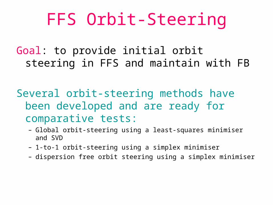
FFS Orbit-Steering
Goal: to provide initial orbit steering in FFS and maintain with FB
Several orbit-steering methods have been developed and are ready for comparative tests:– Global orbit-steering using a least-squares minimiser and SVD– 1-to-1 orbit-steering using a simplex minimiser– dispersion free orbit steering using a simplex minimiser

Comparative Criteria
• Beam size jitter
• IP position jitter
• Average orbit size and jitter
• Max mover moves
• Sensitivity to BPM resolution
• Sensitivity to BPM - magnet alignment
• Sensitivity to corrector/mover errors/resolution

Beamsize after Steering/alignment + EXT disp/coupling correction (100
seeds)
40 45 50 55 60 65 70 75 80 85-2.5
-2.25
-2
-1.75
-1.5
-1.25
-1
-0.75
-0.5
-0.25
0
(
rad
/2 )
S (m)
B5F
F
B2F
F
B1F
F
QD
18X
QF
19X
QD
20X
QF
21X
QM
16F
F
QM
15F
F
QM
14F
F
QM
13F
F
QM
12F
F
QM
11F
F
QD
10B
FF
Q
D10
AF
F
QF
9BF
F
QF
9AF
F
QD
8FF
QF
7FF
QD
6FF
QF
5BF
F
QF
5AF
F
QD
4BF
F
QD
4AF
F
QF
3FF
QD
2BF
F
QD
2AF
F
QF
1FF
QD
0FF
SF
6FF
SF
5FF
SD
4FF
SF
1FF
SD
0FF
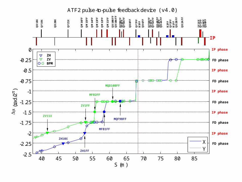
ATF2 pulse-to-pulse feedback devices (v3.7)
XY
IP
IP phase
FD phase
IP phase
FD phase
IP phase
FD phase
IP phase
FD phase
IP phase
FD phase
ZV11X
ZV1FF
MQD10BFF
MFB2FF
ZH10X
ZH1FF
MFB1FF
MQF9BFF
ZHZVBPM
(v4.0)

40 45 50 55 60 65 70 75 80 850
1000
2000
3000
4000
X B
ea
m S
ize
(m
)
40 45 50 55 60 65 70 75 80 850
100
200
300
400
Y B
ea
m S
ize
(m
)
S (m)
ATF2 pulse-to-pulse feedback devices (v3.7)
302.6 µm
0.4 µm
1910.5 µm
7.9 µm
ZHBPM
ZVBPM
(v4.0)
Feedback Plans• Use mover based 1-1 steering for initial steering
of beam• Maintain orbit with FFS pulse-pulse feedback
devices (2 orthogonal stripline kicker-bpm pairs in each plane)– Feedback with low gain (approx 50-pulse step-
response convergence time) to deal with slow drifts and avoid amplifying fast jitter
– Simple integral feedback system used– Open question: how critical is getting correct phase
at 1st vertical bpm fb location? Phase changes fast there- may have to be condition of beta-match?...

EXT Orbit Corrections
• Goal: to provide initial orbit steering in EXT and maintain with FB
• Simulate ATF2 with agreed errors (e.g. wiki list).• Analyze the effects on the stability and the size of the beam.• Development of several algorithms (e.g. "1 to 1", "dispersion free").• Compare the results of all.• Implement the best ones in the Flight Simulator.• Explicit reconstruction and control of the orbit (specially in QM7)• Make Graphical User Interface and User’s guide.• Study the EXT FB implementation, interactions with other FBs.

• static magnets’ misalignment and rolls and BPMs’ resolution.• 11 bits corrector power supplies.• implementation of "1 to 1" method using SVD for EXT+FF.• include correction moving quadrupoles in FF.• specific treatment of correctors’ saturation.• attempt to make orbit reconstruction and control in QM7(ATF).
Simulation of EXT Orbit Corrections
Soon :chose the 1 or 2 best algorithms.implementation in the Flight Simulator (if cavity BPMs
available).
Optimisation :Interaction with other feedback (as soon as others are
available in FS).Handle errors (e.g. Missing BPMs).Orbit reconstruction and control.Compare expected correction and experimental one.
EXT Orbit Correction plans

Beta matching in EXT
Goal: To set correct (designed) Twiss parameters at the exit of EXT (entrance of FF).
1. Measure Twiss parameters around the extraction kicker in DR.:Measurement of tunes changing quad strengths around the kicker.2. Calculate a proper setting of quads in the EXT to match input twiss param. We need to decide which magnets should be changed. Strength of off-center QM7R (?). 3. Measure emittance and Twiss parameters in the EXT using Multi-wire and/or Quad scan methods. 4. Calculate a proper setting of quads in EXT to match into the FFS.
5. Perform 3 again to confirm the matching. 6. Iterate 4 and 5 if necessary.
Procedure needs to be incorporated into tuning simulations.

Controls Implementation
• Code in Flight Simulator environment.
• Write GUI's
• Currently need to program breaks for user input to perform E scan and wirescans.
• Investigate inclusion of EPICS/FS links to wirescanner / E ramp processes.