Embed Size (px)
Citation preview

Status of the MICE Superconducting Solenoids
Tom BradshawSteve VirostekOn behalf of the MICE solenoid groups
Particular thanks to Steve Virostek for supplying slides on the US contributions

• Superconducting solenoids in final configuration:
MICE Superconducting Solenoid Configuration
Solenoid Number Organisation
Spectrometer Solenoids (SS)
2 LBNL – designed and built by Wang NMR,California
Coupling coils (CC) 2 LBNL – designed by Institute of Cryogenics and Superconducting Technology, Harbin. Being built by QiHuan, Beijing.
Absorber and Focus Coil Solenoids (AFC)
3* Oxford University and RAL – Design of intent provided. Engineered and built by Tesla Engineering, Storrington, Sussex.
*Two AFC Modules are required for step V and three for step VI 2

MICE Lattice
MICE Superconducting Solenoid Configuration
3
These are large magnets and design is complicated by the interaction (forces) from the rest of the MICE lattice in the various stages of construction.

• Each magnet has five coils wound on a common Al mandrel• The radiation shield and cold mass are cooled by a series of two-
stage cryocoolers• A recondensation circuit maintains LHe in the cold mass
Spectrometer Solenoid Overview
4

Spectrometer Solenoid Cold Mass
5
Passive Quench Protection Space
Center Coil
Match Coil 1
End Coil 1
Match Coil 2
Coil Cover
LHe Space
490 mm
690 mm
2544 mm
Coil Spacer
End Coil 2
The coils are powered separately, suspension system is massive – has to react against other magnets in the system and withstand quench conditions. Difficult design issues.

• Magnet history:– Both magnets were previously fully assembled and tested– The training goal is to reach 275 amps in all five coils– Magnet #1 trained to 196 amps before disassembly to modify the
recondensing circuit, which was prone to blockage– Magnet #2 was assembled with a modified condensing circuit and several
other design enhancements– The second magnet trained to 238 amps when an HTS lead burned out
due to inadequate cooling of the upper lead ends
Magnet History
6

– Two review committees have been assembled to assess the design and assembly of the Spectrometer Solenoid magnets
– An 11/09 MICE project committee developed recommendations before Magnet #2 was prepared for a 2nd round of testing
– The committee endorsed adding a single-stage cooler to increase the shield and HTS lead cooling
– The committee recommended that the thermal analysis be improved
– With the HTS lead issue solved, Magnet #2 trained to 258 amps when a coil lead was found to contain an open circuit
– Also, the three 2-stage coolers + the 1-stage cooler could not maintain a closed LHe system (per boil-off measurements)
– Magnet #2 has been disassembled and the cold mass opened
– The failed lead was just inside the cold mass feedthrough
Current Spectrometer Solenoid Status
7

Failed lead just inside the cold mass feedthrough
Preliminary Repair of Leads
8
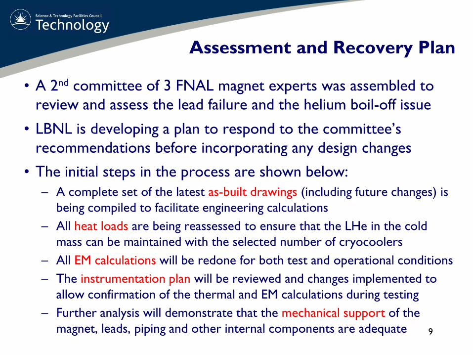
• A 2nd committee of 3 FNAL magnet experts was assembled to review and assess the lead failure and the helium boil-off issue
• LBNL is developing a plan to respond to the committee’s recommendations before incorporating any design changes
• The initial steps in the process are shown below:– A complete set of the latest as-built drawings (including future changes) is
being compiled to facilitate engineering calculations– All heat loads are being reassessed to ensure that the LHe in the cold
mass can be maintained with the selected number of cryocoolers – All EM calculations will be redone for both test and operational conditions– The instrumentation plan will be reviewed and changes implemented to
allow confirmation of the thermal and EM calculations during testing– Further analysis will demonstrate that the mechanical support of the
magnet, leads, piping and other internal components are adequate
Assessment and Recovery Plan
9

• In parallel to the analysis effort, a modification and assembly plan is being developed and will likely include the following:– reduction of heat leaks to the cold mass– the addition of more cryo cooling power– modification of the cold leads near the feedthroughs to prevent burn-out
• The preliminary plan (pending results of analyses) is shown below and on the next slide:– LBNL/MICE personnel will be present to document/oversee all aspects of
magnet reassembly– Improved vacuum pumping and instrumentation will be implemented to
ensure there is adequate insulation of the cold mass– All 4K components will be covered with actively cooled shield where
possible – the effects of partially covered areas will be analyzed
Assessment and Recovery Plan
10

– The total cooling power will be increased by using five 2-stage pulsed tube coolers and one single-stage cooler (preliminary, pending the thermal analysis)
– The thermal/mechanical stabilities of the cold leads will be improved by adding extra copper/superconductor near the cold mass feedthroughs
– The heat loads from the following will be decreased as possible: shield pass through holes for the cold mass supports, intermediate cold mass support heat intercepts, and shielding of the warm end of the supports
– Detailed inspection of MLI during assembly will be part of the QA plan
– The individual leads will be wrapped with super insulation
– Possible thermal acoustic oscillations in vent lines will be addressed
– The vent line heat loads will be evaluated and reduced where possible
– Sensor wires to be optimized to reduce the heat loads as needed
– A fast DAQ system will continuously monitor the voltage tap signals
Design Modifications
11

• The nominal reassembly time for the magnets is expected to be approximately five months
• Actual assembly time will depend on the degree of modification required
SS Schedule
Detailed schedule has yet to be produced by LBNL review committee and agreed with the supplier
12
Steps as above, condensed for clarity

• Thermal calculations– Soren Prestemon (LBNL Engineering Division – Cryogenic Engineer)
• EM analysis– GianLuca Sabbi, Diego Arbelaez (LBNL Supercon Group)
• Mechanical analysis– Steve Virostek (LBNL Engineering Division – Mechanical Engineer)
• Drawings– Steve Virostek, Allan DeMello (LBNL Mechanical Engineers), Wang NMR
• Instrumentation plan– Soren Prestemon, Mike Green (LBNL Cryogenic Engineers), Wang NMR
• Fabrication oversight– Nanyang Li (LBNL Engineering Division – Production Engineer)– Roy Preece (RAL – Engineer ease coordination & integration activities)
• Management & manpower– Steve Gourlay (LBNL AFRD Division Director)– Ross Schlueter (LBNL Mechanical Engineering Department Head)
SS Solenoid Manpower
13

• The Coupling Coils are single coils wound on a forged aluminum mandrel
• Cooling of the radiation shield and cold mass is provided by a series of two-stage cryocoolers
• Liquid helium is maintained in aluminium tubes welded to the cold mass by means of a recondensation circuit
• The coils are designed so as to allow integration with the vacuum vessel for the RF/Coupling Coil (RFCC) Module
• The full MICE cooling channel will contain two of these modules
• A third coil (MuCool) is being built for the MTA Facility at FNAL
• The RFCC vacuum vessel will contain a set of four 201 MHz, normal conducting copper cavities (5 complete, 5 under way)
Coupling Coils
14

Coupling Coil Status• These are being designed and built through
a collaboration with the Institute of Cryogenics and Superconductivity Technology (ICST) in Harbin, China
• The cold-mass design is complete; a fabrication contract was awarded to the QiHuan Company in Beijing in March 2010
• The cryostat design will be complete in September 2010
• A collaboration between LBNL and the Shanghai Institute of Applied Physics will allow the cryostat design to be completed
• The first magnet coil winding is approximately 40% complete
• To test the cold-mass before magnet assembly, the cryogenic test system at ICST must be ready by late November 2010
• The first cold-mass test will be conducted at ICST in Dec. ‘1015

CAD Model and First Coil Winding
• MuCool coil complete 3rd
Quarter 2011• Mice coil #1 2nd
Quarter 2012• MICE coil #2 3rd
Quarter 2012
There is a thin, woven fiberglass cloth that is impregnated with Stycast epoxy between the winding layers.
16
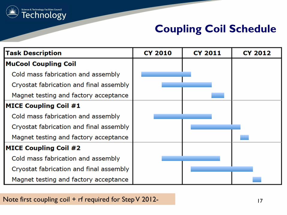
Coupling Coil Schedule
17Note first coupling coil + rf required for Step V 2012-

• Project management at ICST– Fengyu Xu (ICST Project Engineer/Electrical Engineer)
• Engineering design at SINAP (Shanghai Institute of Applied Physics)– Wang Li (SINAP Cryogenic Engineer, formerly ICST Deputy Director)– Prof. Lixin Yin and Yun Cao (SINAP Mechanical Engineers)– Design review scheduled at SINAP for September 13th
• Drawing verification at LBNL– Allan DeMello (LBNL Engineering Division – Mechanical Engineer)– Sisi Shan (LBNL Engineering Student Intern)
• Fabrication oversight– Fengyu Xu of ICST will spend a large portion of his time at the fabricator– The following MICE collaborators will participate in rotating visits to the
QiHuan Company during fabrication (~once per month):– Steve Virostek, Derun Li, Allan DeMello, Nanyang Li (LBNL)– Wang Li (SINAP)– Consultants: M. Green (LBNL), K. Hosoyama (KEK), H. Chen, C. Yi (IHEP)– Periodic visits by other MICE collaborators
CC Manpower
18

AFC being produced by OU and RAL with manufacture at TESLA engineering
Absorber and Focus Coil Cryostat
19

AFC Monitoring
All meeting notes, project files and documentation on web site.
Regular on-site meetings to discuss issues
Risk mitigation activities
20

Status
Formers (bobbins) are being prepared ready for winding – some last minute issues with insulation layer
21

Status
• All major issues are addressed:– Forces on the bobbin– Thermal design, analysis and margin– Quench analysis and protection– Mechanical design complete– Winding tension & thermal contraction issues– Interfaces with lattice, absorber and hydrogen system reviewed– Instrumentation list completed and reviewed– Re-confirming HTS lead design including field tolerance, mechanical and
thermal issues– Assembly and metrology (some issues outstanding)– Quality plan, risk mitigation plan – note that we are looking at the SS
experience very carefully and trying to learn from them.
22
We are mindful that the design has to be correct and it will pay us to be sure and steady at this point
The third AFC Coil
• There is clearly something missing in this plan – the third coil required for Step VI– Contract started with Tesla with a KO meeting on the 18th April 2008– Contract was with an option on a third module– Problem is that the lead times on the superconductor and bobbin forging
are long and these have been delivered. Too late to add to these orders.– Now all procurement will be for one coil only– Oversight costs will be greater– Coil required for Step VI 2013
23

Schedule
Note that after delivery:Field mapping (to be scheduled)*Integration of absorberIntegration of hydrogen delivery system
*Talks held with CERN on field mapping for all the solenoids.
24
Sep Oct Nov Dec Jan Feb Mar Apr May Jun JulFocus Coil Magnet #1 Design Delivery of components Manufacture Assembly Test Delivery to RALIntegration activities Required Q3 2011Focus Coil Magnet #2 Manufacture Assembly Test Delivery to RALAbsorber integration Required 2012
Task Description 2010 2011

• Overview– T Bradshaw (RAL), Wing Lau (OU), John Cobb (OU), Elwyn Baynham
(Consultant)
• Interfaces to absorber and rest of MICE lattice– Wing Lau
• Instrumentation and interface to hydrogen delivery system– Mike Courthold, Matt Hills
• Power Supplies– Mike Courthold
• Management and Fabrication at TESLA– Mark Savill, Mike Nakatsu (thermal modelling and winding), F Goldie
(quench analysis), design office.
• Integration and operation– Victoria Bayliss, Oxford University personnel
AFC Manpower
25

Magnetic Measurements
26
For the spectrometer solenoids a measurement plan exists using the Zip-track device at Fermilab (MICE-note 210) with high precision.-- Requires transport and installation of the magnet at Fermilab-- Not easily applicable to the other magnets
We are presently evaluating a more portable device proposed by the CERN magnet measurement team (F. Bergsma et al)-- would allow measurements at Wang before shipping-- and in situ at RAL-- of all three kinds of MICE magnets
3-D Hall probes
outer radius:15cm (FC)20 cm (SS)22 cm (CC)

27
Spectrometer Solenoid•Clearly have had some issue with the construction of the spectrometer solenoid•Issues have been faced head on•Review committees have addressed not just design and instrumentation but also management and oversight issues •Determined to learn from these experiences and not make same errors in the other procurements•A revised schedule and implementation plan is being drawn up and extra expertise is being drafted in to review the design and assist with the manufacturing oversightCoupling coil•Oversight team has been strengthened•Design has been reviewedAbsorber and Focus Coil •Had several reviews •Strong expert team with differing areas of expertise•Regular review meetings•Good documentation•Need to get issue of third coil procurement resolved
Summary
END