Embed Size (px)
Citation preview

1st Divertor and SOL Physics ITPA Group meeting, GA, San Diego, USA, 25/02/2002 R. A. Pitts
Centre de Recherches en Physique des Plasmas
Status of measurement requirements for the ITER divertor
1R. A. Pitts, 2G. Vayakis, 2A. Costleywith thanks for comments to
A. Kukushkin, D. Whyte1Centre de Recherches en Physique des Plasmas, Association EURATOM-Confédération Suisse, École Polytechnique Fédérale de
Lausanne, CH-1015 Switzerland2ITER-IT, Naka, Japan

1st Divertor and SOL Physics ITPA Group meeting, GA, San Diego, USA, 25/02/2002 R. A. Pitts
Centre de Recherches en Physique des Plasmas
• Recent history of these measurement requirements◆ 13/10/2000: A. Costley gives review of measurement of ITER
divertor plasma and target parameters at SOL and Divertor Physics Expert Group, Garching, - specified (at that time) and estimated measurement performance.
◆ 09/07/2001: A. Costley gives update on divertor measurement requirements at the 14th Divertor and SOL Expert Group meeting in Naka on the basis of some feedback following the Garching meeting. Presentation given in the form of 6 discussion points in key areas requiring attention.
◆ Action item on R. A. Pitts at the Naka meeting to propose a minimum set of requirements on behalf of the SOL and Divertor group, addressing each of the discussion points.
◆ 15/11/2001: G. Vayakis makes a presentation at the first ITPA diagnostics meeting in St. Petersburg using as a base a document transmitted to G. Vayakis and A. Costley containing feedback on the discussion points.

1st Divertor and SOL Physics ITPA Group meeting, GA, San Diego, USA, 25/02/2002 R. A. Pitts
Centre de Recherches en Physique des Plasmas
• This process has led to a set of modified requirements and some actions on the ITPA Diagnostics Group.◆ Aim here is to summarise these measurement specifications
for the ITPA Divertor Group following the lines of the previous presentation by G. Vayakis.
• This is in preparation for the debate to be held in a joint session of the Divertor and Diagnostics ITPA groups on the first morning of the 2nd Diagnostics ITPA meeting: Monday March 4, 2002.
• Apologies in advance for some repetition of previous material - there are some new members in the group.
1st Divertor and SOL Physics ITPA Group meeting, GA, San Diego, USA, 25/02/2002 R. A. Pitts
Centre de Recherches en Physique des Plasmas
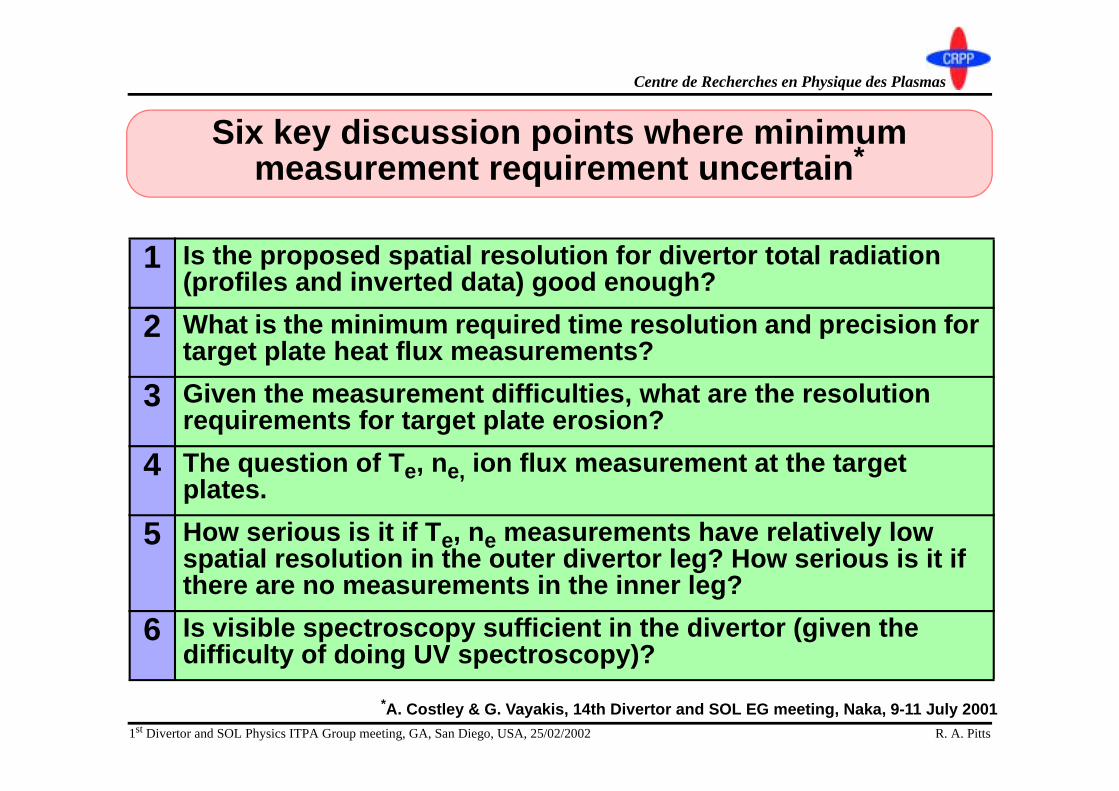
Six key discussion points where minimum measurement requirement uncertain*
1 Is the proposed spatial resolution for divertor total radiation (profiles and inverted data) good enough?
2 What is the minimum required time resolution and precision for target plate heat flux measurements?
3 Given the measurement difficulties, what are the resolution requirements for target plate erosion?
4 The question of Te, ne, ion flux measurement at the target plates.
5 How serious is it if Te, ne measurements have relatively low spatial resolution in the outer divertor leg? How serious is it if there are no measurements in the inner leg?
6 Is visible spectroscopy sufficient in the divertor (given the difficulty of doing UV spectroscopy)?
*A. Costley & G. Vayakis, 14th Divertor and SOL EG meeting, Naka, 9-11 July 2001

1st Divertor and SOL Physics ITPA Group meeting, GA, San Diego, USA, 25/02/2002 R. A. Pitts
Centre de Recherches en Physique des Plasmas
Discussion point #1: radiated Power
• A spatial resolution of 5 cm in the radiated power is all that is likely to be available. Is it enough? What are the consequences if it is > 5 cm, say 10 cm?

1st Divertor and SOL Physics ITPA Group meeting, GA, San Diego, USA, 25/02/2002 R. A. Pitts
Centre de Recherches en Physique des Plasmas
Equatorial Port80 lines of sight
Upper Port60 lines of sight
Upper Port60 lines of sight
Divertor Cassette120 lines of sight
0 500 mm
Div Bolom/LAMx
A
B
C
DE
G
H
F
X
Current proposed LOS: main chamber/divertor
Current design has ~340 lines of sight.Chordal resolution: ~5 cm, spatial resolution after inversion > 10 cm.Concern about lifetime of divertor cameras and strong effect of neutrals.Only very coarse resolution possible if too many divertor chords are lost.Performance improvements presently limited by cash.

1st Divertor and SOL Physics ITPA Group meeting, GA, San Diego, USA, 25/02/2002 R. A. Pitts
Centre de Recherches en Physique des Plasmas
0
20
40
60
80 total
carbon
neon
helium
neutral
A.Kukushkin,H.D.Pacher
5/97
div.inner
m ain &SOL
div.outer
0 2 1 02010021X Xtarget target length [m]
1%C (#136)
2D radiated power profile per unit volume (MW/m3) from all C charge states
Cumulative poloidal radiation integral in inner, outer divertor and SOL
Carbon + 0.2% Ne seeding10% He at core-edge interface
Most of the radiation comes from the divertors, but otherwise well spread outalong the divertor legsIn general, proposed spatial resolution (say 10x10 cm pixel) in an inverted imageshould be acceptable except in strike point zones (especially outer target).Within a tight budget, performance improvements should concentrate onimproving resolution in the target zones if possible.
From G. Janeschitz, L. de Kock, A. Kukushkin et al., “Diagnostic Requirements for the ITER Divertor” in Proc. Int.Workshop on Diagnostics for ITER, Varenna, 1997
Partially attached case

1st Divertor and SOL Physics ITPA Group meeting, GA, San Diego, USA, 25/02/2002 R. A. Pitts
Centre de Recherches en Physique des Plasmas
Discussion point #1: Radiated Power - conclusion
• Presently envisaged potential resolution offered by the divertor (in combination with main chamber LOS) acceptable.
• If possible, performance enhancements to be directed toward improving resolution near the targets.
• Is it worth spending some time investigating the possibility of complementing the system with dead layer AXUV diodes if radiation hardness can be demonstrated?

1st Divertor and SOL Physics ITPA Group meeting, GA, San Diego, USA, 25/02/2002 R. A. Pitts
Centre de Recherches en Physique des Plasmas
Discussion point #2: time resolution and precision of target plate surface temperature/power flux
• We have been asked to consider increasing the time resolution in the target plate measurement [of heat flux] to 20 µµµµs (from 2 ms). On this timescale, we expect the accuracy [of the present system] to be poor (∆∆∆∆T > 200°°°°C). Is this serious? What is the minimum requirement?

1st Divertor and SOL Physics ITPA Group meeting, GA, San Diego, USA, 25/02/2002 R. A. Pitts
Centre de Recherches en Physique des Plasmas
P1
P2
P3
P4P5P6
3210 nm
3915 nm
4340 nm
4630 nm4780 nm
3510 nm
Grating 200 L/mm
Ellipsoidal M irror
7.0 m 7.4 m R
z
1.0 m
0.4 m
Slit 1.6 mm x 40 mm
P1
P2
P3
P4
P5
P6
Horizontal Viewing Duct
?
Current proposed target IR measurement
Concept unchanged from ITER-1998 design. Figures here from DDD 5.5.G.06
A system exists for both target platesSpatial/time resolution: 3 mm/2 ms temperature range: 200 - 2500×°°°°C, wavelength range: 3-5 µµµµm, accuracy, 10%Combined with wide-angle viewing from equatorial portsWide viewing angle makes borescope optics difficult and mulit-element - use wavelength multiplexing collection optics“Inverse Rowland circle” spectrometer - spatial information encoded into wavelength and recovered with a second spectrometer outside biological shield

1st Divertor and SOL Physics ITPA Group meeting, GA, San Diego, USA, 25/02/2002 R. A. Pitts
Centre de Recherches en Physique des Plasmas
Transient ELMs CFC (20 mm)(0.8 MJ/m2 - 200µs, initial heat flux=10 MW/m2)
0
1000
2000
3000
4000
5000
0.00001 0.0001 0.001 0.01 0.1Time, s
0.1
1
10
100
Temperature
Vaporised thickness
Transient ELMs W (15 mm)(0.8 MJ/m2, initial Heat Flux=10 MW/m2)
0
1000
2000
3000
4000
5000
6000
0.00001 0.0001 0.001 0.01 0.1Time, s
Tem
per
atu
re,û
C
0.0001
0.001
0.01
0.1
1
10
100
Vap
ori
sed
/Mel
ted
T
hic
knes
s (µ
m)
Temperature
Melted layer
Vaporised thickness
Requirement for monitoring effects of ELMs
Simulations show that a 200 µµµµs ELM depositing 0.8 MJ/m2 raises Tsurf to melting (sublimation) limit of W (CFC) in a time < 100 µµµµsDepending on inter-ELM power flux, starting temperature could be as low as ~400°°°°C.ITER FDR instrumental resolution would permit time resolution of the order of several µµµµs for Tsurf exceeding 1000°°°°C with high accuracy.Any events leading to Tsurf rise above ~1000°°°°C can ∴ ∴ ∴ ∴ be monitored with high accuracyPoorer performance at low Tsurf not a serious problem - time resolution can be sacrified if no transients.Need more simulation (and understanding) of exactly what to expect for ITER ELMs:
◆ Instrument could be in difficulty for lowstarting Tsurf and “smaller” ELMs
Sensitivity can also be strongly affected by changes in surface ε.ε.ε.ε.
From G. Federici, 14th Divertor SOL EG meeting, Naka, July 2001

1st Divertor and SOL Physics ITPA Group meeting, GA, San Diego, USA, 25/02/2002 R. A. Pitts
Centre de Recherches en Physique des Plasmas
Discussion point #2: Surface temperature - conclusion
• Quoted spatial resolution (~ 3 mm) adequate.• Very high time resolution (µµµµs) and sensitivity for high
Tsurf near divertor target operating limits. Perfectly adequate for ELM monitoring.
• Some potential problems if low starting Tsurf and “smaller” ELMs.
• Potential difficulties under conditions when surfaces change radically (and quickly) under erosion/redeposition (common to any system).
• Need to use any new ITER ELM simulations as they come to re-evaluate instrument performance.
• More emphasis should be placed on the use of tile thermocouples (but water cooling makes it harder).
1st Divertor and SOL Physics ITPA Group meeting, GA, San Diego, USA, 25/02/2002 R. A. Pitts
Centre de Recherches en Physique des Plasmas
Discussion point #3: target plate erosion
• It is suggested that the resolution in the measurement of target plate erosion should be 0.1 µµµµm for a single Type I ELM in real time. It will not be possible to meet this; 100 µµµµm is more likely. How serious is this?

1st Divertor and SOL Physics ITPA Group meeting, GA, San Diego, USA, 25/02/2002 R. A. Pitts
Centre de Recherches en Physique des Plasmas
• “Quiescent case: no ELMs no disruptions (“semi-detached, most recent case”)*◆ Peak net erosion rate: ~6 (< 0.0005) nm/s for C (W)◆ Tritium co-deposition rate: 1-5 (~0) mg/s for C(W)
• →→→→ If C used in the divertor, ~3 µµµµm per 500s pulse eroded and ~500g T retained after 200, 8 min. pulses.
• Situation unknown but probably much worse in case of ELMs, disruptions etc. (depending on the ELMs ITER will have).
• Erosion measurements are difficult and so important to specify as carefully as possible the minimum requirements
• What should be the functionality of the system(s)?
*From G. Federici, 14th Divertor SOL EG meeting, Naka, July 2001

1st Divertor and SOL Physics ITPA Group meeting, GA, San Diego, USA, 25/02/2002 R. A. Pitts
Centre de Recherches en Physique des Plasmas
• Function 1: “tread” wear: signs of divertor end of life.• Function 2: “Real time” capability: avoid dangerous
regimes for the divertor when they are encountered, monitor ELM induced erosion etc.◆ For C targets, erosion measurement can also be an indirect
indicator of approximate T-retention.◆ “Real time” would allow “erosion budgets” to be set for the
operators - could even be one of the control categories. • Function 1: Range finding system forseen (periscopic
insertion between pulses) covering ~80% of the targets and first wall with spot size ~1mm and “depth” resolution ± ± ± ± 0.1-0.5 mm.
• Function 2: Interferometric/range finding techniques might be extendable to 10’s µµµµm and could conceivably be made real time (several sec. time res.) but this seems unlikely (and will be toroidally localised).
1st Divertor and SOL Physics ITPA Group meeting, GA, San Diego, USA, 25/02/2002 R. A. Pitts
Centre de Recherches en Physique des Plasmas
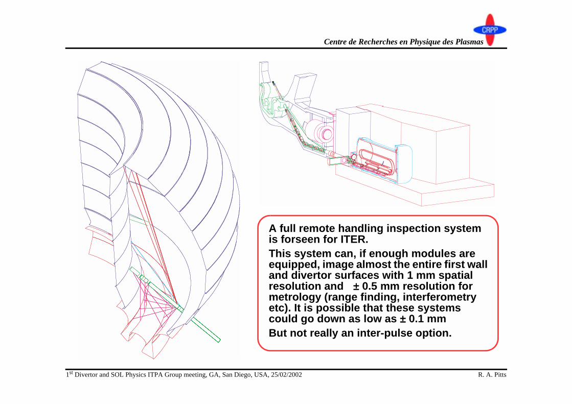
A full remote handling inspection system is forseen for ITER. This system can, if enough modules are equipped, image almost the entire first wall and divertor surfaces with 1 mm spatial resolution and ±±±± 0.5 mm resolution for metrology (range finding, interferometry etc). It is possible that these systems could go down as low as ±±±± 0.1 mmBut not really an inter-pulse option.
1st Divertor and SOL Physics ITPA Group meeting, GA, San Diego, USA, 25/02/2002 R. A. Pitts
Centre de Recherches en Physique des Plasmas
• Feasibility studies etc. required to find limitations of any proposed technique for real time (or at least inter-pulse), divertor localised observations.
• What minimum realistic measurement requirements can physics impose?

1st Divertor and SOL Physics ITPA Group meeting, GA, San Diego, USA, 25/02/2002 R. A. Pitts
Centre de Recherches en Physique des Plasmas
Discussion point #4: target plate probe measurements
• It will probably not be possible to measure reliably the plasma parameters (ne and Te) at the target but only the ion flux with Langmuir probes. How serious is this? What are the consequences?

1st Divertor and SOL Physics ITPA Group meeting, GA, San Diego, USA, 25/02/2002 R. A. Pitts
Centre de Recherches en Physique des Plasmas
Proposed system has 3 groups of ~80 CFC single probes with ~1 cm pitch arranged as triple probes (as in JET)Probe is of JET designPotential problems with RIC and RIEDUnknown how long these will survive in full performance discharges (or even before then).Survival only realistically possible in partially detached, cold divertors
• Probes an excellent indicator of detachment (via ion flux), with no problems of interpretation (except changes in Aproj).
• The usual problems of interpretation of absolute value of Te in high recycling - appears difficult to solve, but relative changes in Te could be usefully employed.
• System should be more than adequate and should be included. Lifetime issues impossible to judge for ITER using only JET experience.

1st Divertor and SOL Physics ITPA Group meeting, GA, San Diego, USA, 25/02/2002 R. A. Pitts
Centre de Recherches en Physique des Plasmas
Discussion points #5,6: Te and spectroscopy in the divertor
• Measurement of Te along the outer divertor leg is very difficult. There will be high resolution measurements in the upper SOL region (main chamber) and there could be some across the X-point. How serious is it if there are no measurements along the divertor leg? If there are, what should be the spatial resolution?
• It is difficult to make UV measurements in the divertor - will visible be good enough if good bolometry measurements are available.
• Presently no provision for measurements along the inner leg. How serious is this?

1st Divertor and SOL Physics ITPA Group meeting, GA, San Diego, USA, 25/02/2002 R. A. Pitts
Centre de Recherches en Physique des Plasmas
3.194
BIO-SHIELD
UPPER-PORT (2 port apart Toridally)
EQUATORIAL-PORT (next Troidal port)
X-POINT
23
OVIH
12
IVOH
DIVERTOR-PORT
DIVERTOR-CASSETTE
Divertor (imaging) and X-point (LIDAR) Thomson Divertor impurity monitor
Two systems forseen: outer leg and X-pt. LIDAR system expected to provide 5 cm spatial resolution, target for divertor system is ~10 cm (both with 1 ms time res.)Inner leg viewing practically impossible (3 potential sightlines along inner leg could be provided by divertor reflectometry).Divertor TS cannot be swept poloidally, at least not in real time. Poloidal res. ~ 1 cm
Combined viewing from main chamber and divertor give resolution along legs of ~ 4 cm and possibility for crude inversion giving 5-10 cm resolution for main impurities (C, W, Be) and D,T (200 - 500 nm)Number of sightlines reduced in going from FDR to FEAT (shorter divertor legs and cost).
1st Divertor and SOL Physics ITPA Group meeting, GA, San Diego, USA, 25/02/2002 R. A. Pitts
Centre de Recherches en Physique des Plasmas
0
5 1020
1 1021
.5 1021
2 1021
9 9.2 9.4 9.6 9.8 10 10.2
Poloidal distance [m]
x-point target
0
20
40
60
80
00
20
40
9 9.2 9.4 9.6 9.8 10 10.2
Poloidal distance [m]
x-point target
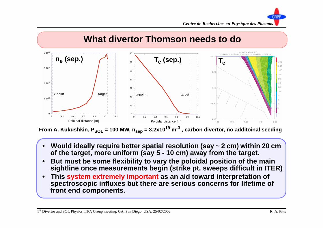
From A. Kukushkin, PSOL = 100 MW, nsep = 3.2x10¹⁹ m-3 , carbon divertor, no additoinal seeding
What divertor Thomson needs to do
• Would ideally require better spatial resolution (say ~ 2 cm) within 20 cm of the target, more uniform (say 5 - 10 cm) away from the target.
• But must be some flexibility to vary the poloidal position of the main sightline once measurements begin (strike pt. sweeps difficult in ITER)
• This system extremely important as an aid toward interpretation of spectroscopic influxes but there are serious concerns for lifetime of front end components.
ne (sep.) Te (sep.) Te
1st Divertor and SOL Physics ITPA Group meeting, GA, San Diego, USA, 25/02/2002 R. A. Pitts
Centre de Recherches en Physique des Plasmas
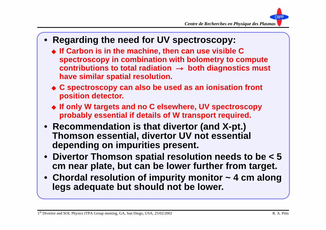
• Regarding the need for UV spectroscopy:◆ If Carbon is in the machine, then can use visible C
spectroscopy in combination with bolometry to compute contributions to total radiation →→→→ both diagnostics must have similar spatial resolution.
◆ C spectroscopy can also be used as an ionisation front position detector.
◆ If only W targets and no C elsewhere, UV spectroscopy probably essential if details of W transport required.
• Recommendation is that divertor (and X-pt.) Thomson essential, divertor UV not essential depending on impurities present.
• Divertor Thomson spatial resolution needs to be < 5 cm near plate, but can be lower further from target.
• Chordal resolution of impurity monitor ~ 4 cm along legs adequate but should not be lower.

1st Divertor and SOL Physics ITPA Group meeting, GA, San Diego, USA, 25/02/2002 R. A. Pitts
Centre de Recherches en Physique des Plasmas
Summary of revisions to ITER-FEAT FDR divertor requirements (changes in red)*
MEASUREMENT PARAMETER RANGE or COVERAGE
RESOLUTION Temporal Spatial
ACCURACY
16. Divertor operational parameters
Max. Surface Temp. 200 - 2500°°°°C 2 ms - 10%Erosion rate 0.1 - 1 µµµµm/s 2 s 1 cm 30%Net Erosion 0 - 3 mm Per pulse 1 cm 12 µµµµm
Ionis. front position 0 - TBD m 1 ms 10 cm -
37. Radiation profile
X-pt./MARFE region Prad
TBD - 300 MWm-2
10 ms a/15 20%
Divertor Prad TBD - 100 MWm-2
10 ms 5 cm 30%
38. Heat loading profile in divertor
Surface Temp. 200 - 1000°°°°C1000 - 2500°°°°C
2 ms20 µµµµs
3 mm 10%10%
Power load(default)
TBD - 25 MWm-2
2 ms 3 mm 10%
41. Divertor electron
parameters
ne 1019 - 1022 m-3 1 ms 5 cm along leg, 3 mm across leg
20%
Te 0.3 - 200 eV 1 ms 5 cm along leg, 3 mm across leg
20%
41. Divertor ion temperature
Ti 0.3 - 200 eV 1 ms 5 cm along leg, 3 mm across leg
20%
*Minutes of 1st ITPA Diagnostics group N CX MI 6 02-01-11-F1
1st Divertor and SOL Physics ITPA Group meeting, GA, San Diego, USA, 25/02/2002 R. A. Pitts
Centre de Recherches en Physique des Plasmas
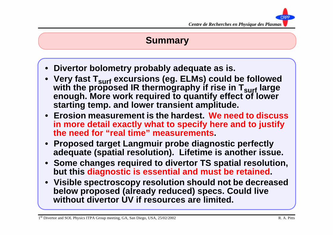
Summary
• Divertor bolometry probably adequate as is.• Very fast Tsurf excursions (eg. ELMs) could be followed
with the proposed IR thermography if rise in Tsurf large enough. More work required to quantify effect of lower starting temp. and lower transient amplitude.
• Erosion measurement is the hardest. We need to discuss in more detail exactly what to specify here and to justify the need for “real time” measurements.
• Proposed target Langmuir probe diagnostic perfectly adequate (spatial resolution). Lifetime is another issue.
• Some changes required to divertor TS spatial resolution, but this diagnostic is essential and must be retained.
• Visible spectroscopy resolution should not be decreased below proposed (already reduced) specs. Could live without divertor UV if resources are limited.