Embed Size (px)
Citation preview

Delft University of Technology
Statistical Analysis of Energization Overvoltages in EHV Hybrid OHL-Cable Systems
Khalilnezhad, Hossein; Popov, Marjan; Sluis, Lou van der; Bos, Jorrit A.; Ametani, Akihiro
DOI10.1109/TPWRD.2018.2825201Publication date2018Document VersionFinal published versionPublished inIEEE Transactions on Power Delivery
Citation (APA)Khalilnezhad, H., Popov, M., Sluis, L. V. D., Bos, J. A., & Ametani, A. (2018). Statistical Analysis ofEnergization Overvoltages in EHV Hybrid OHL-Cable Systems. IEEE Transactions on Power Delivery,33(6), 2765-2775. https://doi.org/10.1109/TPWRD.2018.2825201
Important noteTo cite this publication, please use the final published version (if applicable).Please check the document version above.
CopyrightOther than for strictly personal use, it is not permitted to download, forward or distribute the text or part of it, without the consentof the author(s) and/or copyright holder(s), unless the work is under an open content license such as Creative Commons.
Takedown policyPlease contact us and provide details if you believe this document breaches copyrights.We will remove access to the work immediately and investigate your claim.
This work is downloaded from Delft University of Technology.For technical reasons the number of authors shown on this cover page is limited to a maximum of 10.

Green Open Access added to TU Delft Institutional Repository
'You share, we take care!' - Taverne project
https://www.openaccess.nl/en/you-share-we-take-care
Otherwise as indicated in the copyright section: the publisher is the copyright holder of this work and the author uses the Dutch legislation to make this work public.

IEEE TRANSACTIONS ON POWER DELIVERY, VOL. 33, NO. 6, DECEMBER 2018 2765
Statistical Analysis of Energization Overvoltagesin EHV Hybrid OHL–Cable Systems
Hossein Khalilnezhad , Graduate Student Member, IEEE, Marjan Popov , Senior Member, IEEE, Lou van derSluis, Life Senior Member, IEEE, Jorrit A. Bos, and Akihiro Ametani , Life Fellow, IEEE
Abstract—Energization overvoltages are among the severestovervoltages stressing insulations of EHV power system compo-nents. Since these overvoltages have a statistical nature, the in-sulation level should be determined with the use of a statisticalapproach by which the distribution of overvoltages is calculated.Literature has properly studied the distribution of energizationovervoltages in purely overhead line (OHL) or cable systems, butsuch a study is not available for hybrid systems consisting of bothOHLs and cables. It is expected that the overvoltage distributionschange substantially when both OHLs and cables are used in atransmission line. This paper tackles this issue by analyzing theovervoltage distributions due to the energization of a 380 kV hy-brid OHL-cable circuit, in which the cable length is variable. Thestudy includes various sensitivity analyses to find out the impact ofsystem parameters and topology on overvoltages. By the statisticalanalysis, it has been discovered that energization overvoltages ofa hybrid OHL–cable circuit are higher than those of a fully-cablecircuit and very likely lower than those of a fully-OHL circuit withthe same transmission lengths.
Index Terms—Cables, energization overvoltages, insulation co-ordination, switching transients, statistical analysis.
I. INTRODUCTION
POWER transmission systems have been traditionally devel-oped mainly by the use of overhead lines (OHLs). However,
with the increasing tendency in the application of EHV under-ground cables, future grids will be composed of OHLs andcables combined. These grids are known as hybrid OHL-Cabletransmission systems.
The transient behavior of a hybrid OHL-Cable system is sig-nificantly different from an OHL-based system due to substan-tial differences between electrical characteristics of OHLs andcables. As a result, several questions have been raised concern-ing the technical operation and reliability of hybrid grids [1],
Manuscript received November 2, 2017; revised February 27, 2018; acceptedMarch 24, 2018. Date of publication April 9, 2018; date of current versionNovember 20, 2018. This work was supported in part by TenneT TSO B.V.,Arnhem, The Netherlands, within the framework of the 380 kV cable researchprogram. Paper no. TPWRD-01331-2017. (Corresponding author: HosseinKhalilnezhad.)
H. Khalilnezhad, M. Popov, and L. van der Sluis are with the Delft Univer-sity of Technology, Delft 2628CD, The Netherlands (e-mail:,[email protected]; [email protected]; [email protected]).
J. A. Bos is with TenneT TSO B.V, Arnhem, 7186800, The Netherlands(e-mail:,[email protected]).
A. Ametani is with Doshisha University, Kyoto 610-0321 Japan (e-mail:,[email protected]).
Color versions of one or more of the figures in this paper are available onlineat http://ieeexplore.ieee.org.
Digital Object Identifier 10.1109/TPWRD.2018.2825201
[2]. A very important question is how the statistical distributionof energization overvoltages would be in hybrid systems andwhich parameters can affect their significance.
The determination of the statistical distribution of ener-gization overvoltages is highly recommended for insulationcoordination studies due to the statistical nature of switchingactions and the insulation strength. The risk of an insulationfailure can be calculated by the comparison of the overvolt-age probability distribution and the insulation breakdownprobability distribution [3]–[5].
The statistical nature of energization overvoltages is the resultof the random behavior of the circuit-breaker closing time. Thebreaker contacts can be switched at any point on the voltagewaveform with a pole closing span. The pole closing span is thetime difference between the first and the last pole to close dueto different stochastic variations in the operating time of eachpole [6], [7].
The detailed study of the statistical distribution of line ener-gization overvoltages (OHL or cable) are addressed in [8]–[17].In [12], [13], the statistical distribution of energization over-voltages in EHV cables and OHLs are compared, where it isconcluded that overvoltages in a cable line are lower than thosein an OHL. However, despite the importance of the issue, there isvery limited literature related to the statistical switching analysisof hybrid circuits consisting of OHLs and cables combined.
It is reported in [18] that energization overvoltages in acable system are in general lower than those in an OHL-Cablesystem. In [19], authors concluded that energization overvolt-ages of a hybrid OHL-Cable circuit are lower than those ina purely OHL circuit and higher than those in a purely cablecircuit. However, these conclusions cannot be generalized asthe mentioned studies ignore the breaker pole span and alsothey are only for one circuit topology and one set of systemparameters.
A more comprehensive study is required for hybrid systemswhere the impacts of various system topologies and parametersare investigated; most notably, the cable length, configuration ofthe hybrid OHL-Cable circuit, short cable sections, and systemshort-circuit power. In practice, the distribution of overvoltagescan be significantly different from one system to another andthis can be identified by a sensitivity analysis.
The aim of this paper is to address the mentioned crucial sci-entific gaps and perform sensitivity analyses on system param-eters to investigate the statistical distribution of transient ener-gization overvoltages in hybrid OHL-Cable circuits. In addition,
0885-8977 © 2018 IEEE. Personal use is permitted, but republication/redistribution requires IEEE permission.See http://www.ieee.org/publications standards/publications/rights/index.html for more information.
Authorized licensed use limited to: TU Delft Library. Downloaded on August 18,2021 at 05:52:40 UTC from IEEE Xplore. Restrictions apply.

2766 IEEE TRANSACTIONS ON POWER DELIVERY, VOL. 33, NO. 6, DECEMBER 2018
TABLE ICABLE SCENARIOS FOR THE HYBRID OHL-CABLE CIRCUIT
Fig. 1. Study case mixed-line configuration with LEC.
overvoltages due to the presence of trapped charges in the cableare also studied.
II. STUDY CONSIDERATIONS
To ensure the comprehensiveness and preciseness of thestudy, a wise approach of modelling and simulation had to beconsidered to drive the statistical distribution of energizationovervoltages in hybrid OHL-Cable systems.
A. Cable Scenarios
Six cable scenarios were defined to determine the influence ofthe cable length on the distribution of energization overvoltagesin hybrid circuits. In each scenario, it is specified how manykilometers of the total transmission length is realized by cables.The total transmission length of the hybrid circuit under study is80 km from the sending substation to the receiving substation.By these scenarios, the cable share varies from 0% (fully OHL)to 100% (fully cable) of the transmission length. The cablescenarios are presented in Table I.
B. Mixed-Line Configuration
A hybrid OHL-Cable circuit is composed of solidly series-connected OHL and cable sections. Mixed-line is the term thatis usually used to refer to these circuits. The configuration of amixed-line is determined by the number and location of OHLand cable sections, which can be decided in the planning anddesign stages of hybrid circuits.
Fig. 1 shows the study case mixed-line configuration of thispaper. The circuit has four OHL sections and three cable sec-tions, where the cable sections are composed of two parallelcables per phase to achieve the same transmission capacity asthe OHL sections.
The three-phase shunt reactors for reactive power compen-sation are connected to the circuit at the two remote ends(right behind the line breakers) through their own breakers(breakers 3 and 4). This type of compensation is known asline-end compensation (LEC).
TABLE IITRANSMISSION LENGTHS OF OHL AND CABLE SECTIONS
IN EACH CABLE SCENARIO
TABLE IIIREQUIRED SHUNT COMPENSATION SIZE FOR EACH CABLE SCENARIO
The connection of shunt reactors to the circuit helps to limitenergization overvoltages in the circuit, especially at the open-end due to the Ferranti effect, and to minimize the capacitivecurrent in the line breaker. These benefits cannot be achievedwhen shunt reactors are connected to busbars or to tertiary wind-ings of power transformers at substations [20].
The installation of separate breakers for the shunt reactorsresults in an added switching flexibility as well as minimizingthe risk of open phase resonance by decoupling reactors fromthe disconnected phase(s). If reactors remain connected to thedisconnected phase(s), resonance may occur between the reactorinductance, inter-phase/inter-circuit capacitance, and the cablecapacitance [21], [22].
Table II presents the lengths of the OHL and cable sectionsin each cable scenario reported in Table I. The defined sectionlengths are unequal since an asymmetrical mixed-line configu-ration is a more realistic assumption than a symmetrical one inwhich the circuit is identical at the two sides of the mid-point.Usually, realization of a completely symmetrical mixed-lineconfiguration is difficult due to the practical limitations.
Table III presents the required shunt compensation size foreach cable scenario. These values were obtained by a steady-state analysis presented in [20], which is based on the proposedmethod in [23]–[25]. SR1 and SR2 refer to the three-phase shuntreactors at the sending-end and receiving-end of the circuit,respectively, and the reported value for each of them is thetotal three-phase size. Ksh is the shunt compensation degree andshows the percentage of the cable reactive power compensatedby the shunt reactors.
C. Grid Modeling
The time-domain simulations were carried out in thefrequency-dependent model of the whole Dutch 380 kVtransmission system in PSCAD/EMTDC. This model repre-sents the entire Dutch 380 kV grid with frequency-dependentmodels to ensure the maximum simulation accuracy.
Authorized licensed use limited to: TU Delft Library. Downloaded on August 18,2021 at 05:52:40 UTC from IEEE Xplore. Restrictions apply.

KHALILNEZHAD et al.: STATISTICAL ANALYSIS OF ENERGIZATION OVERVOLTAGES IN EHV HYBRID OHL–CABLE SYSTEMS 2767
Fig. 2. Sheath cross-bonding and cable layout in the trench.
This model includes detailed representations of 380 kV sub-stations, transmission lines, and three-phase three-limb powertransformers, where the core saturation and parasitic capaci-tances of transformers are also included. The shunt reactors arerepresented by a multi-layer model and 380 kV capacitor banksby equivalent RLC circuits. The detailed explanations on themodelling of transformers and shunt reactors are available in[26]. The capacitor banks exist at some substations for voltagecontrol and they are switched-in/out depending on the load-flowand voltage level. Equivalent parallel RL or RC loads were usedfor the representation of the lower voltage levels (220 kV andbelow).
In this model, OHLs and XLPE cables are represented by thefrequency-dependent phase model of PSCAD, which is basedon the Universal Line Model theory [27]. The input data of themodel is based on the actual geometry and material propertiesof the represented transmission lines. The parameters used forthe hybrid circuit under study can be found in [19]. The cable issingle-core 2500 mm2 copper conductor with XLPE insulation.
Fig. 2 illustrates the cable sheath cross-bonding and cablelayout in the trench. It was assumed that the cable sections arecomposed of minor sections with the length of 1 km each. Thescreen conductors are cross-bonded at the end of each minorsection (every 1 km) and they are grounded at the ends of eachmajor section, which is made of three minor sections. A de-tailed model of each cross-bonding was applied in the Dutchgrid model as a discrete representation of each minor sectionis the most accurate way of modelling [28]. The bonding wireand grounding impedance are represented by 1 μH inductancesfor cross-bonding joints, 10 μH inductances for groundings atstraight through joints (connection of two major sections), and1 mΩ resistances for groundings at cable terminations [29].
III. STATISTICAL BEHAVIOR OF CIRCUIT-BREAKER
The breaker closing time (Tclose) is the instant when thebreaker connects a phase to the voltage source and it can beexpressed as follows [6], [14]:
Tclose = Tcommand + ΔTknown + ΔTstochastic︸ ︷︷ ︸
ΔTo p e r a t in g
(1)
where Tcommand is the instant at which the breaker receives theclosing command and ΔToperating is the breaker operating timerepresenting the required time for the control and mechanicalparts of the breaker to operate. ΔTknown is the known and pre-dictable part of the operating time (from measurements and/oradaptive control) and ΔTstochastic is the unpredictable variationin the operating time indicating the randomness of the closingtime.
ΔTstochastic can be different between the poles due to theseparate mechanical systems and it has a random behavior ac-cording to the normal distribution [6]–[17], [19]. The stochasticvariations (inherent scatter) of the operating time can result inenergization of phases at different instants, known as the poleclosing span.
With regards to (1), the statistical behavior of the breaker clos-ing time can be represented if two parameters are determined:(1) mean closing time, Tmean , where Tmean = Tcommand +ΔTknown , (2) pole closing span or distribution of pole closingtimes around the mean closing time (ΔTstochastical). A sufficientnumber of these two parameters should be simulated to obtainaccurate energization overvoltage distributions [14], [17], [30].
IV. STATISTICAL SIMULATION APPROACH
The statistical analysis of energization overvoltages is moreaccurate when a larger number of switching times are simulated,but this requires a long computation time especially when abig and complex grid is modelled. For instance, each singleswitching simulation in the PSCAD model of the Dutch 380 kVgrid can take up to a few hours to be completed dependingon the simulated cable length. Such a long simulation timeis mainly caused by the small numerical integration time step(Δt = 4.8 μs) and a large number of cables.
In [9]–[11], 100 random line energizations were performedto produce the overvoltage distributions, whilst the analysis wasconducted in [12] by 200 random line energization cases. Lit-erature has recommended minimum 100 simulations to obtaina sufficiently accurate overvoltage distribution [14], [17], [19],[30]. In this paper, 400 energizations were carried out for eachstudy case to maximize the accuracy of the obtained statisticaldistributions. The applied approach for the selection of Tmeanand the pole closing span is illustrated in Fig. 3:
1. Tmean : it was assumed that the breakers of the line andshunt reactors receive the closing command simultane-ously and they have the same Tmean . The mean closingtime can be any point of the power-frequency voltage cy-cle. 100 random points (with uniform distribution) werechosen by using the multiple-run feature of PSCAD.
2. Pole closing span: for each Tmean , 4 sets of pole clos-ing span were simulated for each breaker. The pole spanwas determined by a random number generator using thenormal (Gaussian) distribution. The mean value of thenormal distribution was Tmean and the standard deviationwas 1 ms (σ = 1 ms). The normal distribution curve wastruncated at −3σ and +3σ.
The phase-peak method was applied to obtain the overvoltageprobability distribution for each study case [3]. This means thatfrom each energization simulation, the peak value of the phase-
Authorized licensed use limited to: TU Delft Library. Downloaded on August 18,2021 at 05:52:40 UTC from IEEE Xplore. Restrictions apply.
2768 IEEE TRANSACTIONS ON POWER DELIVERY, VOL. 33, NO. 6, DECEMBER 2018
Fig. 3. Statistical variation of the breaker closing time over a cycle of thepower-frequency voltage.
to-earth overvoltage on each phase at the point of interest wasincluded in the overvoltage probability distribution. Therefore,the representative probability distribution for each case has 1200overvoltage peak values (3 peak values per simulation × 400simulations).
V. SIMULATION RESULTS AND ANALYSIS
The no-load energization overvoltages of the hybrid circuitwere simulated while it was energized from substation A andwas open at the other side (see Fig. 1). The effects of cablelength, shunt compensation size/location, short cable sections,short-circuit power, trapped charges, and mixed-line configura-tion on overvoltages were studied.
Throughout the paper, the point of interest is always the lineopen-end, unless a different location is mentioned. The overvolt-ages are expressed in per unit, where the base value (1 pu) is thepeak value of the phase-to-ground nominal voltage (310.27 kV).Surge arresters are not modelled so that the worst overvoltagescan be simulated.
The power-frequency and the transient voltages are the twocomponents of the total switching overvoltage, so the obtainedmaximum overvoltages depend on the power-frequency volt-age, which is here 1.076 pu (333.85 kV phase-to-ground). Theshort-circuit power at the substation from which the hybrid cir-cuit is energized (substation A) is 26.3 GVA (corresponding to37.14 kA fault current or 20 mH equivalent source inductancecalculated at 408.88 kV = (333.85 kV ×
√3√2 ).
A. Effect of Cable Length
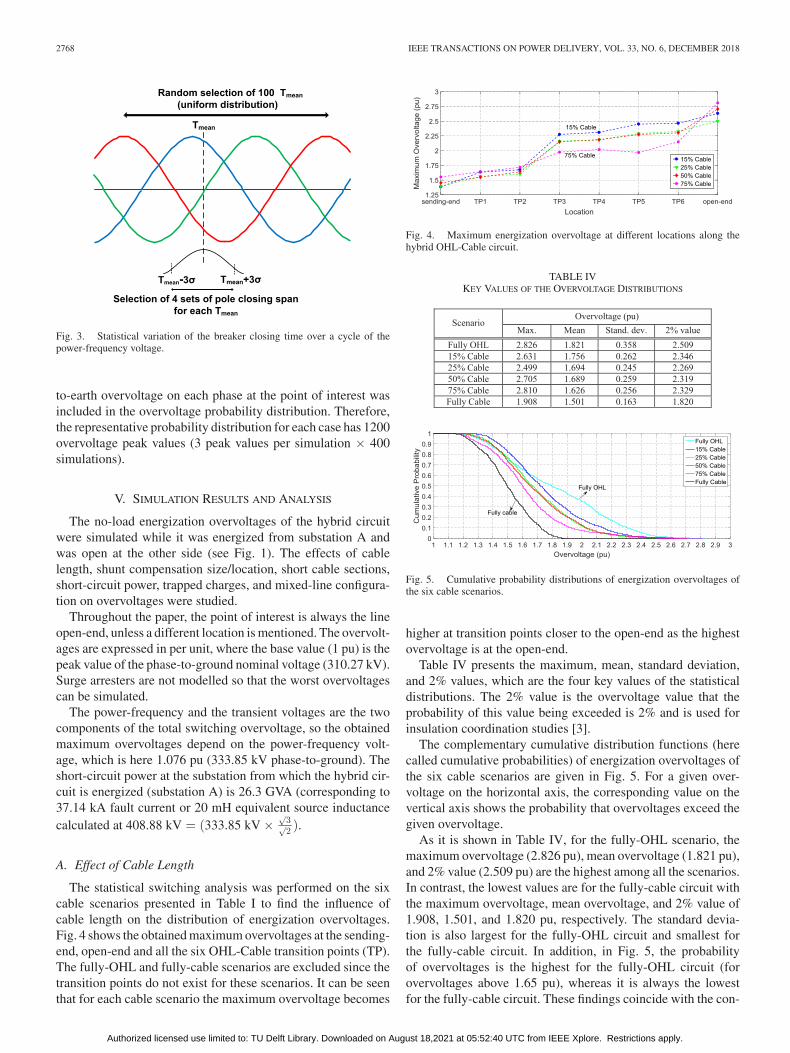
The statistical switching analysis was performed on the sixcable scenarios presented in Table I to find the influence ofcable length on the distribution of energization overvoltages.Fig. 4 shows the obtained maximum overvoltages at the sending-end, open-end and all the six OHL-Cable transition points (TP).The fully-OHL and fully-cable scenarios are excluded since thetransition points do not exist for these scenarios. It can be seenthat for each cable scenario the maximum overvoltage becomes
Fig. 4. Maximum energization overvoltage at different locations along thehybrid OHL-Cable circuit.
TABLE IVKEY VALUES OF THE OVERVOLTAGE DISTRIBUTIONS
Fig. 5. Cumulative probability distributions of energization overvoltages ofthe six cable scenarios.
higher at transition points closer to the open-end as the highestovervoltage is at the open-end.
Table IV presents the maximum, mean, standard deviation,and 2% values, which are the four key values of the statisticaldistributions. The 2% value is the overvoltage value that theprobability of this value being exceeded is 2% and is used forinsulation coordination studies [3].
The complementary cumulative distribution functions (herecalled cumulative probabilities) of energization overvoltages ofthe six cable scenarios are given in Fig. 5. For a given over-voltage on the horizontal axis, the corresponding value on thevertical axis shows the probability that overvoltages exceed thegiven overvoltage.
As it is shown in Table IV, for the fully-OHL scenario, themaximum overvoltage (2.826 pu), mean overvoltage (1.821 pu),and 2% value (2.509 pu) are the highest among all the scenarios.In contrast, the lowest values are for the fully-cable circuit withthe maximum overvoltage, mean overvoltage, and 2% value of1.908, 1.501, and 1.820 pu, respectively. The standard devia-tion is also largest for the fully-OHL circuit and smallest forthe fully-cable circuit. In addition, in Fig. 5, the probabilityof overvoltages is the highest for the fully-OHL circuit (forovervoltages above 1.65 pu), whereas it is always the lowestfor the fully-cable circuit. These findings coincide with the con-
Authorized licensed use limited to: TU Delft Library. Downloaded on August 18,2021 at 05:52:40 UTC from IEEE Xplore. Restrictions apply.

KHALILNEZHAD et al.: STATISTICAL ANALYSIS OF ENERGIZATION OVERVOLTAGES IN EHV HYBRID OHL–CABLE SYSTEMS 2769
Fig. 6. Probability distributions of energization overvoltages of the six cablescenarios with fitted normal distribution curves.
TABLE VSKEWNESS AND KURTOSIS OF THE ENERGIZATION
OVERVOLTAGE DISTRIBUTIONS
clusions of [12] and [13] that line energization overvoltages incables are lower than those in OHLs.
According to Table IV, the hybrid scenarios produce overvolt-ages lower than those of the fully-OHL circuit and higher thanthose of the fully-cable circuit. The mean overvoltage decreasesby increasing the cable length in the hybrid circuit, but the max-imum overvoltage can decrease or increase depending on thecable scenario. Moreover, in Fig. 5 and for overvoltages above1.65 pu, the overvoltage probabilities of the hybrid scenariosare between those of the fully-OHL and fully-cable circuits.
It can be concluded form the statistical simulations that apartial or full replacement of an overhead transmission linewith cables results in lower energization overvoltages. It shouldbe noted that for partial cabling cases this conclusion is a ruleof thumb and may not be always valid due to its dependencyon the system topology and parameters (e.g., see Sections V-D,V-E, and V-G for three exception examples).
The probability distributions of energization overvoltages ofthe six cable scenarios with fitted normal distribution curves areshown in Fig. 6. The probability distributions of random ener-gization cases are usually compared to the normal distribution.The y-axis (height of rectangle) is the frequency with which theovervoltages in the specified range (width of rectangle) haveoccurred. Table V presents the skewness and kurtosis values ofthe overvoltage distributions.
The skewness is a measure describing how symmetricallythe data are distributed around the mean value. The skewnessof any symmetric distribution like the normal distribution is
zero. A negative skewness indicates that the data has a longertail to the left side of the mean value and a positive skewnessindicates that the data has a longer tail to the right side. Theovervoltage probability distributions of all the scenarios havepositive skewness and are spread out more to the right sideof the mean values. The fully-cable scenario has the smallestskewness indicating that its overvoltages probability distributionis the most symmetrical one.
The kurtosis is a measure of how outlier-prone (heavy- orlight-tailed) a distribution is. Higher kurtosis indicates that thedistribution is more outlier-prone (heavier-tailed) and lower kur-tosis indicates that the distribution is less outlier-prone (lighter-tailed). The kurtosis of the normal distribution is 3. Accordingto Table V, the fully-OHL scenario with the kurtosis of 2.084 isthe less outlier prone scenario.
It has been observed that the energization overvoltages cansubstantially change when the share of cable in the circuit isvaried. To interpret the simulation results, the significant phys-ical differences between cables and OHLs, which influence theenergization overvoltages, should be discussed.
The first difference between cables and OHLs is the propa-gation velocity and the behavior of the modal waves. Accord-ing to the modal decomposition theory, a cross-bonded three-phase single-core cable system can be decomposed into sixmodes: one coaxial mode, two inter-phase modes, two inter-sheath modes, and one ground mode (in contrast to only oneinter-phase mode and one earth-return mode for an OHL). Eachmode has its own attenuation constant and propagation veloc-ity [28], [31]–[33]. The wave propagation velocity in cablesis much lower than that of OHLs as the coaxial mode is thefastest with the propagation velocity of C0√
εr μrm/s, where εr
and μr are respectively the relative permittivity and permeability(compared to C0 = 3 × 10⁸ m/s for OHLs). For a typical cable,the propagation velocity is approximately between 1.6 × 10⁸
to 1.8 × 10⁸ m/s. If a cable is cross-bonded, the propagationvelocity is slightly lower than these values [33].
During transients when an energizing wave propagates intothe cable core conductor, all the six modal waves are excitedand propagate toward the open-end while they reflect and refractat every impedance discontinuity point (impedance mismatchpoint), where the line surge impedance changes. Therefore, theresulting overvoltage at a given location on the circuit is thesuperimposition of all the modal waves at that location. As itis discussed in [13], the maximum energization overvoltage atthe cable open-end is determined by the superimposition ofthe inter-phase mode (as the dominant mode) and the coax-ial mode (as the superimposed mode), where the cycle timeof the inter-phase mode (dominant mode) is dependent on theshort-circuit power and the cable length. The overvoltages ofthe coaxial mode are low (compared with those of the inter-phase mode in OHLs) and also the cycle time of the inter-phase mode in cables is generally long. These two factors re-sult in lower energization overvoltages for cables comparedto OHLs.
The second difference between cables and OHLs is the exis-tence of cross-bonding points for cables, which makes it moredifficult for the waves to propagate to the open-end [12]. Fur-thermore, the third difference is the smaller surge impedance of
Authorized licensed use limited to: TU Delft Library. Downloaded on August 18,2021 at 05:52:40 UTC from IEEE Xplore. Restrictions apply.

2770 IEEE TRANSACTIONS ON POWER DELIVERY, VOL. 33, NO. 6, DECEMBER 2018
cables compared to that of OHLs, leading to lower overvoltagesin cables for a same switching surge current [12], [34].
In addition to the mentioned differences between cables andOHLs, explanation about the reflection and refraction of thepropagating waves in hybrid OHL-Cable circuits is also usefulfor interpretation of the simulation results. When an electro-magnetic wave propagating along a hybrid circuit arrives to animpedance discontinuity point (sheath cross-bonding joints andOHL-Cable transition points), a part of the incident wave is re-flected back and a part of the wave is transmitted beyond thepoint. The reflected voltage wave (VR ) and the transmitted volt-age wave (VT ) can be calculated by the following equations [35]:
VR =Z2 − Z1
Z2 + Z1. V (2)
VT =2Z2
Z2 + Z1. V (3)
where, V is the incident voltage wave, Z1 is the surgeimpedance of the first transmission line through which theincident wave is traveling, and Z2 is the surge impendence ofthe second transmission line.
In the case study project, the surge impedances of the OHLsand cables are around 220 Ω and 50 Ω, respectively. So, accord-ing to (2) and (3), when a voltage wave traveling through anOHL section reaches a transition point to a cable section, about63% of the wave is reflected back with the negative polarity(with respect to the incident wave) and about 37% of the waveis transmitted to the cable. In contrary, when a wave travelingthrough a cable section reaches a transition point to an OHLsection, about 63% of the wave is reflected back into the cablewith the positive polarity (with respect to the incident wave) and163% of the wave is transmitted to the OHL.
When a circuit consists of cascade connection of several OHLand cable sections, like the case study project, the propagatingswitching surge produces reflected and transmitted waveformsat all the impedance discontinuity points. This leads to a verycomplex propagation pattern, which can be analyzed by a latticediagram. In this situation, the voltage at a given point on thecircuit is determined by the superimposition of all the waves atevery instant of time. The highest overvoltages occur when thebest condition in terms of the system topology and parameters(e.g., number and location of sections and short-circuit power)are provided for the superposition of the waves.
B. Effect of Compensation Size
The shunt reactors are generally sized and located based ona steady-state analysis to control the power-frequency voltageand the capacitive current in the line breakers [20]. To deducethe impact of shunt reactors on the statistical distribution ofenergization overvoltages, the statistical analysis was conductedwithout shunt compensation and the results were compared withthose of the shunt compensated circuit.
Table VI presents the key values of the overvoltage dis-tributions and Fig. 7 shows the cumulative probabilities ofenergization overvoltages without and with shunt compensa-tion. In all the cable scenarios, except the fully-cable scenario,the maximum overvoltage and the 2% value are lower when the
TABLE VIKEY VALUES OF THE OVERVOLTAGE DISTRIBUTIONS WITHOUT SHUNT
COMPENSATION (VALUES IN PARENTHESES ARE
WITH SHUNT COMPENSATION)
Fig. 7. Cumulative probability distributions of energization overvoltages withshunt compensation (solid lines) and without shunt compensation (dashed lines).
circuit is energized without shunt compensation. In addition,for these scenarios, the probability of high overvoltages (above1.7 pu) is lower when the circuit is energized without shuntcompensation, although the post-switching steady-state over-voltages will be higher due to the Ferranti effect. This couldbe due to the superposition of the energization transients of thereactors and line when they are energized together.
C. Effect of Compensation Location
The location of shunt reactors can be LEC (see Fig. 1) ordistributed at multiple points along the route of the circuit. Thetechnical convenience of the former or the latter has been as-sessed in [23] and [36], where the shunt compensation alloca-tion for different study cases has been analyzed. The LEC is themost common scheme whereas the distributed techniques havemultiple advantages over it; most notably, the increase of theavailable capacity for active power transfer and the need for alower degree of compensation [20].
To deduce the influence of compensation location on the sta-tistical distribution of energization overvoltages, overvoltagesof a distributed compensation scheme in which reactors are lo-cated at each cable termination (OHL-Cable transition point)were compared with those of LEC. This type of compensationis called cable-end compensation (CEC). Therefore, instead oftwo reactor banks at two substations, six reactors banks (one ateach cable termination) were considered with the sizes reportedin [20].
Table VII presents the key values of the overvoltage distri-butions and Fig. 8 shows the cumulative probabilities of ener-gization overvoltages with CEC and LEC. The key values andcumulative probabilities of overvoltages in all CEC scenarios
Authorized licensed use limited to: TU Delft Library. Downloaded on August 18,2021 at 05:52:40 UTC from IEEE Xplore. Restrictions apply.

KHALILNEZHAD et al.: STATISTICAL ANALYSIS OF ENERGIZATION OVERVOLTAGES IN EHV HYBRID OHL–CABLE SYSTEMS 2771
TABLE VIIKEY VALUES OF THE OVERVOLTAGE DISTRIBUTIONS WITH CEC
(VALUES IN PARENTHESES ARE WITH LEC)
Fig. 8. Cumulative probability distributions of energization overvoltages withLEC (solid lines) and CEC (dashed lines).
are lower than those of the LEC scenarios, indicating anotheradvantage of distributed compensation over the line-end com-pensation.
D. Effect of Short Cable Sections
In practice, short cable sections may be realized in a hy-brid circuit. The short traveling time of the wave in short cablesections results in consecutive reflections and refractions at ter-mination points leading to different overvoltages. To investigatethis issue, six cases with short cable sections were defined forthe 15% cable scenario. As illustrated in Fig. 9, the lengths ofthe OHL sections are unchanged in all the cases and only thelengths of the cable sections are varied while the total cablelength is constant (12 km). Case 1 is the base case as definedin Table II. Cases 2, 3, and 4 have a 1 km-long cable section atthe sending side, middle, and the receiving side of the circuit,respectively. Cases 5 and 6 have two 1 km-long cable sectionsat middle plus the sending or receiving sides.
The maximum overvoltages and the cumulative probabilitiesof energization overvoltages are respectively shown in Figs. 10and 11. It can be observed that Case 6 has the highest maximumovervoltage (3.3 pu) and overvoltage probability among all thecases even higher than those of the fully-OHL scenario. On thecontrary, Case 5 has the lowest maximum (2.44 pu) and proba-bility of overvoltages. In addition, after Case 6, the highest max-imum and probability of overvoltages are produced in Case 4.
It can be concluded that for a given cable scenario, the highestenergization overvoltages are expected when very short cablesections are at the open-end of the circuit. For the studied cases,these overvoltages are up to 0.86 pu (equal to 267 kV) higherthan those of the other cases. In contrast, the existence of longer
Fig. 9. Cases of short cable sections for the 15% cable scenario (lengths ofthe OHL sections are unchanged).
Fig. 10. Maximum energization overvoltage at different locations along thehybrid OHL-Cable circuit for the cases in Fig. 9.
Fig. 11. Cumulative probability distributions of energization overvoltages ofthe cases in Fig. 9.
cable sections at the open-end results in lower overvoltages.This can be due to the short travelling time of the propagatingwave in the short cable sections and the successive reflectionsand refractions.
E. Effect of Short-Circuit Power
The influence of the grid short-circuit power on the statis-tical distribution of energization overvoltages was studied bythe use of an equivalent grid model consisting of the hybridcircuit and a lumped-parameter inductive source. In fact, theThevenin equivalent was used instead of the whole grid modelwith distributed generation because it is more flexible and con-venient to adjust the short-circuit power with the variation of theequivalent source impedance. A Frequency Dependent NetworkEquivalent (FDNE) can be also an option to represent the entiregrid if it can properly represent the generation and short-circuitpower of the grid [37].
In the equivalent model of the grid, the power-frequency volt-age at the sending substation was adjusted to the same voltagein the whole grid model (1.076 pu). The statistical analysiswas carried out for five source inductances of 15, 20, 25, 50,and 100 mH. The 20 mH source inductance is equal to theequivalent short-circuit inductance calculated at the sendingsubstation in the whole grid model.
Authorized licensed use limited to: TU Delft Library. Downloaded on August 18,2021 at 05:52:40 UTC from IEEE Xplore. Restrictions apply.

2772 IEEE TRANSACTIONS ON POWER DELIVERY, VOL. 33, NO. 6, DECEMBER 2018
Fig. 12. Maximum energization overvoltage and 2% value for different feed-ing network short-circuit powers.
Fig. 12 shows the maximum energization overvoltage and2% value for different feeding networks. For a given sourceinductance, the lowest and highest values are for the fully-cableand the fully-OHL scenarios, respectively. The only exceptionis the 50% cable scenario with 25 mH source inductance, forwhich the maximum overvoltage (3.36 pu) is higher than thatof the fully-OHL circuit although the corresponding 2% valueis still lower. In addition, for all source impedances, the hybridscenarios produce overvoltages higher than those of the fully-cable scenario and very likely lower than those of the fully-OHLscenario. This conclusion coincides with those in the previoussections.
It can be also noticed that each cable scenario has a differentbehavior than the other scenarios when the short-circuit power isvaried. For the fully-OHL scenario, the maximum overvoltagedecreases when the source inductance increases from 15 mHto 50 mH and thereafter slightly increases for 100 mH; how-ever, the 2% value always decreases with increasing the sourceimpedance (weaker feeding networks). For the fully-cable sce-nario, both the maximum overvoltage and 2% value decreaseby increasing the source impedance. For the hybrid scenarios,the dependency of overvoltages on the feeding network strengthchanges case-by-case.
As it was previously mentioned, the maximum energizationovervoltage at the cable open-end is determined by superim-position of the inter-phase mode (as the dominant mode) andthe coaxial mode (as the superimposed mode), where the cycletime of the inter-phase mode is dependent on the short circuitpower and the cable length [13]. For larger source impedances(weaker feeding networks), the rate of rise of voltage is lowerand the cycle time of the inter-phase mode (dominant mode) islonger. Thus, by the time when the inter-phase mode reaches itsmaximum at the open-end, the coaxial mode has travelled backand forth to the open-end for several times and has becomehighly damped. As a result, the energization overvoltage willbe likely lower when the source impedance is larger (weakerfeeding network).
TABLE VIIIKEY VALUES OF THE OVERVOLTAGE DISTRIBUTIONS WITH TRAPPED CHARGES
(VALUES IN PARENTHESES ARE WITHOUT TRAPPED CHARGES)
Fig. 13. Cumulative probability distributions of energization overvoltageswithout trapped charges (solid lines) and with trapped charges (dashed lines).
Fig. 14. Single-line diagram of the simulated mixed-line configurations.
The comparison of the simulated overvoltages of the wholegrid model in Table IV with those of the equivalent model with20 mH source inductance (as the corresponding inductance withthe short-circuit power of the whole grid model) shows that thesimulated overvoltages are higher in the equivalent grid. This isdue to the fact that the actual damping and wave propagation tothe rest of the grid are not represented by the equivalent model.
F. Effect of Trapped Charges
Trapped charges may exist on disconnected cables and re-sult in very high overvoltages when the voltage of the trappedcharges has opposite polarity to that of the switching surge[38]. The study was conducted by initial charging of the cableswith three single-phase 30 kV dc voltage sources and then thestatistical switching of the breakers whilst the dc sources areremoved.
Authorized licensed use limited to: TU Delft Library. Downloaded on August 18,2021 at 05:52:40 UTC from IEEE Xplore. Restrictions apply.

KHALILNEZHAD et al.: STATISTICAL ANALYSIS OF ENERGIZATION OVERVOLTAGES IN EHV HYBRID OHL–CABLE SYSTEMS 2773
Fig. 15. Cumulative probability distributions of energization overvoltages for different mixed-line configurations.
Table VIII and Fig. 13 show the key values of the overvolt-age distributions and the cumulative probability distributions,respectively. The maximum overvoltages are up to 0.68 puhigher than those of the cases without trapped charge, whereasthe difference in 2% values is much less and only up to 0.07 pu.Moreover, the differences between the cumulative probabilitiesare negligible, indicating that generally overvoltages are nothigher except for particular switching instants at which the re-sulting switching surge and trapped charges cause a very highovervoltage together. It should be noted that higher overvoltagescan be expected if the residual voltage on the cables is higherthan 30 kV.
G. Effect of Mixed-Line Configuration
It is also important to investigate the influence of mixed-lineconfiguration on the statistical distribution of energization over-voltages. Different configurations can be derived by varying thenumber and location of the OHL and cable sections. In additionto the study case configuration in Fig. 1, four mixed-line config-urations as shown in Fig. 14 were selected for the comparison.As it is concluded in [20], the required compensation size foreach configuration is different, so the reported values in [20]were used for this study. In addition, for a given cable scenarioand configuration, it was assumed that all the OHL sections areequally long and the same for all the cable sections.
The cumulative probabilities of energization overvoltages areshown in Fig. 15. For a given cable scenario, the differencebetween the cumulative probabilities of different configurationscan be up to 35%. Therefore, the number and distribution of theOHL and cable sections can substantially affect overvoltagesdue to the consequent changes in the wave propagation pattern.
In addition, Configuration 1, in which a long cable section isat the open-end of the circuit, produces the lowest overvoltagesfor all the scenarios. This finding coincides with the conclusionsof Section V.D. The reason that Configuration 1 produces lowerovervoltages than the other configurations is as follows: whenthe traveling voltage wave through the OHL section reaches the
transition point to the cable section, about 63% of the incidentwave is reflected back (see (2) and (3)) and only 37% of theincident wave is transmitted to the cable and moving towardthe open-end. So, the resulting overvoltage at the open-end ofthe circuit will be lowered.
VI. CONCLUSIONS
The statistical distribution of energization overvoltages playsan important role in determination of the required insulationlevels for EHV components. In this paper, the distribution ofenergization overvoltages of hybrid OHL-Cable circuits wasthoroughly studied by means of numerous statistical switchingsimulations.
It was discovered that a hybrid OHL-Cable circuit producesenergization overvoltages higher than those of a fully-cable cir-cuit and very likely lower than those of a fully-OHL circuit withthe same transmission lengths. This means that the risk of ex-periencing high energization overvoltages and stressing systemcomponents is higher in a fully-OHL circuit than in a partial orfully undergrounded circuit.
Energization overvoltages are very dependent on the number,location, and lengths of the OHL and cable sections because ofthe consequent changes in the energizing wave propagation. Fora given cable scenario, the existence of long cable sections atthe open-end of the circuit results in lower energization over-voltages compared to the case that short cable sections are at theopen-end. In addition, the difference between the overvoltagecumulative probabilities of different mixed-line configurationscan be also substantial, where, as an example, it was up to 35%for the studied configurations in this paper. This shows the highimpact of the number and distribution of the OHL and cablesections on energization overvoltages.
Furthermore, energization overvoltages can be substantiallyaffected by the system parameters, most notably the short-circuitpower of the feeding network and the shunt compensation sizeand location. The transient energization overvoltages will belikely lower when the network short-circuit power is lower (i.e.,
Authorized licensed use limited to: TU Delft Library. Downloaded on August 18,2021 at 05:52:40 UTC from IEEE Xplore. Restrictions apply.

2774 IEEE TRANSACTIONS ON POWER DELIVERY, VOL. 33, NO. 6, DECEMBER 2018
weaker feeding network), whereas the post-switching steady-state overvoltages will be higher due to the Ferranti effect atthe open-end of the circuit. Moreover, a distributed reactivepower compensation along the circuit, like CEC, results in lowerovervoltages compared to the line-end compensation.
Finally, in specific situations, extremely high overvoltagesmay occur in hybrid OHL-Cable circuits, such as the presenceof trapped charges on the cable, the existence of very short cablesections at the open-end of the circuit, and certain short-circuitpowers. A special attention should be paid to these situationsas they can lead to a component failure and/or exceeding theenergy absorption capacity of surge arresters and sheath voltagelimiters.
REFERENCES
[1] CIGRE Working Group C4.502, “Power system technical performanceissues related to the application of long HVAC cables,” CIGRE, Paris,France, Tech. Brochure 556, Oct. 2013.
[2] R. Benato and D. Napolitano, “State-space model for availability assess-ment of EHV OHL–UGC mixed power transmission link,” Elect. PowerSyst. Res., vol. 99, pp. 45–52, 2013.
[3] Insulation Co-Ordination-Part 2: Application Guide, IEC Standard 60071-2, 1996.
[4] CIGRE Working Group 21/33, “Insulation co-ordination for HV AC un-derground cable systems,” CIGRE, Paris, France, Tech. Brochure 189,Jun. 2001.
[5] A. R. Hileman, Insulation Coordination for Power Systems. New York,NY, USA: Marcel Dekker, Jun. 1999.
[6] R. Smeets, L. van der Sluis, M. Kapetanovic, D. Peelo, and A. Janssen,Switching in Electrical Transmission and Distribution Systems. Hoboken,NJ, USA: Wiley, 2015.
[7] ABB, Ludvika, Sweden, Live Tank Circuit Breakers: Buyer’s Guide, 6thed., 2014.
[8] CIGRE Working Group 13.02, “Switching overvoltages in EHV and UHVsystems with special reference to closing and reclosing transmission lines,”Electra, no. 30, pp. 70–122, 1973.
[9] CIGRE Working Group 13.05, “The calculation of switching surges,”Electra, no. 19, pp. 67–78, 1971.
[10] CIGRE Working Group 13.05, “The calculation of switching surges-II. Network representation for energization and re-energization stud-ies on lines fed by an inductive source,” Electra, no. 32, pp. 17–42,1974.
[11] CIGRE Working Group 13.05, “The calculation of switching surges-III.Transmission line representation for energization and re-energization stud-ies with complex feeding networks,” Electra, no. 62, pp. 45–78, 1979.
[12] T. Ohno, C. L. Bak, A. Ametani, W. Wiechowski, and T. K. Sørensen,“Statistical distribution of energization overvoltages of EHV cables,” IEEETrans. Power Del., vol. 28, no. 3, pp. 1423–1432, Jul. 2013.
[13] T. Ohno, A. Ametani, C. L. Bak, W. Wiechowski, and T. K. Sørensen,“Analysis of the statistical distribution of energization overvoltages ofEHV cables and OHLs,” in Proc. Int. Conf. Power Syst. Transients, Van-couver, BC, Canada, Jul. 2013, pp. 1–7.
[14] P. Mestas and M. C. Tavares, “Relevant parameters in a statistical analysis-application to transmission-line energization,” IEEE Trans. Power Del.,vol. 29, no. 6, pp. 2605–2613, Dec. 2014.
[15] A. H. Hamza, S. M. Ghania, A. M. Emam, and A. S. Shafy, “Statisti-cal analysis of switching overvoltages and insulation coordination for a500 kV transmission line,” in Proc. 18th Int. Middle East Power Syst.Conf., Cairo, Egypt, Dec. 2016, pp. 1–4.
[16] M. Z. Daud, P. Ciufo, and S. Perera, “Statistical analysis of overvoltagesdue to the energization of a 132 kV underground cable,” in Proc. 6th ECTIConf., Pattaya, Thailand, May 2009, pp. 54–57.
[17] J. A. Martinez, R. Natarajan, and E. Camm, “Comparison of statisticalswitching results using Gaussian, uniform and systematic switching ap-proaches,” in Proc. IEEE Power Eng. Soc. Summer Meeting, Seattle, WA,USA, Jul. 2000, pp. 884–889.
[18] Y. Itoh, N. Nagaoka, and A. Ametani, “Transient analysis of a crossbondedcable system underneath a bridge,” IEEE Trans. Power Del., vol. 5, no. 2,pp. 527–532, Apr. 1990.
[19] H. Khalilnezhad, M. Popov, J. A. Bos, J. P. W. de Jong, and L. van derSluis, “Investigation of statistical distribution of energization overvoltagesin 380 kV hybrid OHL-cable systems,” in Proc. Int. Conf. Power Syst.Transients, Seoul, South Korea, Jun. 2017, pp. 1–6.
[20] H. Khalilnezhad, S. Chen, M. Popov, J. A. Bos, J. P. W. de Jong, andL. van der Sluis, “Shunt compensation design of EHV double-circuitmixed OHL-cable connections,” in Proc. IET Int. Conf. Resilience Trans-miss. Distrib. Netw., Birmingham, U.K., 2015, pp. 1–6.
[21] CIGRE Working Group C4.307, “Resonance and feroresonancein power networks,” CIGRE, Paris, France, Tech. Brochure 569,Feb. 2014.
[22] H. Khalilnezhad, M. Popov, J. A. Bos, J. P. W. de Jong, L. van der Sluis, andA. Ametani, “Countermeasures of zero-missing phenomenon in (E)HVcable systems,” IEEE Trans. Power Del., vol. 33, no. 4, pp. 1657–1667,Aug. 2018.
[23] S. Lauria, F. M. Gatta, and L. Colla, “Shunt compensation of EHV cablesand mixed overhead-cable lines,” in Proc. IEEE Power Technol. Conf.,Lausanne, Switzerland, Jul. 2007, pp. 1344–1349.
[24] F. M. Gatta, A. Geri, S. Lauria, and M. Maccioni, “Steady-state operationconditions of very long EHVAC cable lines,” Elect. Power Syst. Res.,vol. 81, pp. 1525–1533, 2011.
[25] R. Benato and A. Paolucci, EHV AC Undergrounding Electrical Power:Performance and Planning. Berlin, Germany: Springer, 2010.
[26] L. Wu, “Impact of EHV/HV underground power cables on resonant gridbehavior,” Ph.D. dissertation, Dept. Elect. Eng., Eindhoven Univ. Tech-nol., Eindhoven, The Netherlands, Oct. 2014.
[27] Manitoba HVDC Research Centre, Winnipeg, MB, Canada, “User’sguide on the EMTDC analysis for PSCAD power system simulation,”2010.
[28] I. Lafaia, J. Mahseredjian, A. Ametani, M. T. Correia de Barros, I. Kocar,and Y. Fillion, “Frequency and time domain response of cross-bondedcables,” IEEE Trans. Power Del., vol. 33, no. 2, pp. 640–648, Apr. 2018.
[29] U. S. Gudmundsdottir, B. Gustavsen, C. L. Bak, and W. Wiechowski,“Field test and simulation of a 400-kV cross-bonded cable system,” IEEETrans. Power Del., vol. 26, no. 3, pp. 1403–1410, Jul. 2011.
[30] A. I. Ibrahim and H. W. Dommel, “A knowledge base for switching surgetransients,” in Proc. Int. Conf. Power Syst. Transients, Montreal, QC,Canada, 2005, pp. 1–6.
[31] F. F. da Silva and C. L. Bak, Electromagnetic Transients in Power Cables.London, U.K.: Springer, 2013.
[32] C. F. Jensen, U. S. Gudmundsdottir, C. L. Bak, and A. Abur, “Field testand theoretical analysis of electromagnetic pulse propagation velocityon crossbonded cable systems,” IEEE Trans. Power Del., vol. 29, no. 3,pp. 1028–1034, Jun. 2014.
[33] A. Ametani, T. Ohno, and N. Nagaoka, Cable System Transients: Theory,Modeling and Simulation. Singapore: Wiley, Jul. 2015.
[34] CIGRE Working Group B1.30, “Cable systems electrical characteristics,”CIGRE, Paris, France, Tech. Brochure 531, Apr. 2013.
[35] A. Greenwood, Electrical Transients in Power Systems. Hoboken, NJ,USA: Wiley, 1971.
[36] R. Benato and A. Paolucci, “Operating capability of long AC EHV trans-mission cables,” Elect. Power Syst. Res., vol. 75, pp. 17–27, 2005.
[37] J. Morales, J. Mahseredjian, K. Sheshyekani, A. Ramirez, E. Medina,and I. Kocar, “Pole-selective residue perturbation technique for passivityenforcement of FDNEs,” IEEE Trans. Power Del., vol. 33, no. 6, pp. 2746–2754, Dec. 2018.
[38] F. Ghassemi, “Effect of trapped charges on cable SVL failure,” Elect.Power Syst. Res., vol. 115, pp. 18–25, 2014.
Hossein Khalilnezhad (GSM’12) was born in Iranin 1987. He received the B.Sc. degree in electrical en-gineering from the Shiraz University of Technology,Shiraz, Iran, and the M.Sc. degree (cumlaude) in elec-trical power engineering from the Delft University ofTechnology, Delft, The Netherlands, in September2013. He is currently working toward the Ph.D. de-gree at the Delft University of Technology, wherehe studies EHV underground cable systems. He wasthe recipient of the Shell Master Award for the bestM.Sc. thesis in the field of innovation and technology
in March 2014 and the IEEE PES Travel Grant at the POWERCON Conferencein Australia in September 2016.
Authorized licensed use limited to: TU Delft Library. Downloaded on August 18,2021 at 05:52:40 UTC from IEEE Xplore. Restrictions apply.
KHALILNEZHAD et al.: STATISTICAL ANALYSIS OF ENERGIZATION OVERVOLTAGES IN EHV HYBRID OHL–CABLE SYSTEMS 2775
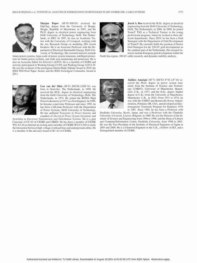
Marjan Popov (M’95–SM’03) received theDipl.Ing. degree from the University of Skopje,Skopje, Republic of Macedonia, in 1993, and thePh.D. degree in electrical power engineering fromDelft University of Technology, Delft, The Nether-lands, in 2002. In 1997, he was an Academic Vis-itor with the University of Liverpool, working withthe Arc Research Group on modeling SF6 circuitbreakers. He is an Associate Professor with the De-partment of Electrical Sustainable Energy, Delft Uni-versity of Technology. His research interests include
future power systems, large scale of power system transients, intelligent protec-tion for future power systems, and wide area monitoring and protection. He isalso an Associate Editor for Elsevier’s JEPES. He is a member of CIGRE andactively participated in Working Group C4.502 and Working Group A2/C4.39.He was the recipient of the prestigious Dutch Hidde Nijland Award in 2010, theIEEE PES Prize Paper Award, and the IEEE Switchgear Committee Award in2011.
Lou van der Sluis (M’81–SM’86–LSM’16) wasborn in Geervliet, The Netherlands, in 1950. Hereceived the M.Sc. degree in electrical engineeringfrom the Delft University of Technology, Delft, TheNetherlands, in 1974. He joined the KEMA HighPower Laboratory in 1977 as a Test Engineer. In 1990,he became a part-time Professor and since 1992, hehas been a full-time Professor with the Departmentof Power Systems, Delft University of Technology.He has authored Transients in Power Systems andcoauthor of Electrical Power System Essentials and
Switching in Electrical Transmission and Distribution Systems. He is a pastConvener of CC-03 of CIGRE and CIRED. He has been a member of CIGREWG A3-24 on internal arc testing and a member of CIGRE WG C4-502 to studythe interaction between high-voltage overhead lines and underground cables. Heis a member of the advisory board of SC-A3 of CIGRE.
Jorrit A. Bos received the M.Sc. degree in electricalengineering from the Delft University of Technology,Delft, The Netherlands, in 2008. In 2008, he joinedTenneT TSO as a Technical Trainee in the youngprofessional program, where he worked in three dif-ferent departments. Since 2010, he has been a GridStrategist with the Department of Grid Developmentof TenneT. He currently holds the position of SeniorGrid Strategist for the 150 kV grid developments inthe southern part of the Netherlands. His research in-terests include European grid development within the
North Sea region, 380 kV cable research, and dynamic stability analysis.
Akihiro Ametani (M’71–SM’83–F’92–LF’10) re-ceived the Ph.D. degree in power system tran-sients from the Institute of Science and Technol-ogy (UMIST), University of Manchester, Manch-ester, U.K., in 1973, and the D.Sc. degree (higherdegree in U.K.) from the University of Manchester,Manchester, U.K., in 2010. From 1971 to 1974, hewas with the UMIST and Bonneville Power Admin-istration, Portland, OR, USA, and developed an Elec-tromagnetic Transients Program for Summers 1976to 1981. Since 1985, he has been a Professor with
Doshisha University, Kyoto, Japan, and was a Professor with the ChatholicUniversity of Leaven, Leuven, Belgium, in 1988. He was the Director of the In-stitute of Science and Engineering from 1996 to 1998, and the Dean of Libraryand Computer/Information Center, Doshisha University, from 1998 to 2001.He was the Vice-President of the Institute of Electrical Engineers of Japan in2003 and 2004. He is a Chartered Engineer in the U.K., a Fellow of IET, and adistinguished member of CIGRE.
Authorized licensed use limited to: TU Delft Library. Downloaded on August 18,2021 at 05:52:40 UTC from IEEE Xplore. Restrictions apply.