Embed Size (px)
Citation preview

siemens.com/energy/arrester
Product guide IEEE
Station and intermediate class surge arresters

Definition of surge arrestersSurge arresters are used to protect high-voltage equipment in substations, such as transformers, circuit breakers, and bushings, against the effects of overvoltages caused by incoming surges. Such overvoltages can be caused by a direct or nearby lightning strike, an electromagnetic pulse, electrostatic discharge, or switching operations in the power supply system as well as in devices. Some overvoltages are very high in energy. The current from the surge is diverted through the arrester, in most cases to earth. Effective over-voltage protection requires different surge arrester types to be used according to the particular application.
2

Contents
Definition of surge arresters 02
Siemens surge arresters for any requirement 04
Always the best solution 05
History timeline 06
MOVs: the core of Siemens surge arresters 08
Silicone rubber 09
Porcelain 10
Station and intermediate class surge arresters 11
3EL silicone rubber surge arresters with Cage Design 12
3EQ silicone rubber surge arresters with composite hollow core design 14
3EP porcelain surge arresters 16
Standards and testing – reliability you can count on 17
Selection table and how to select a suitable surge arrester 18
Applications as line surge arresters 23
Early detection of relevant changes through efficient equipment monitoring 24
Product range 26
3EL5 Surge arrester with silicone rubber housing and Cage Design™ 28
3EL1 Surge arrester with silicone rubber housing and Cage Design™ 32
3EL2 Surge arrester with silicone rubber housing and Cage Design™ 36
3EL3 Surge arrester with silicone rubber housing and Cage Design™ 42
3EP5 Surge arrester with porcelain housing 48
3EP4 Surge arrester with porcelain housing 52
3EP6 Surge arrester with porcelain housing 58
3EQ1 Surge arrester with composite hollow core design 64
3EQ4 Surge arrester with composite hollow core design 68
Accessories for surge arresters 74
Monitoring devices for surge arresters 74
3
Siemens surge arresters for any requirement
Experience is most essential when it comes to reliability in medium- and high-voltage applications. Siemens has been designing and manufacturing medium- and high-voltage surge arresters for standard and special applications since 1925. Continuous research and development, the wealth of Siemens know-how, and comprehensive worldwide experience give Siemens surge arresters a leading edge in overvoltage protection. Their uncompromising quality ensures a long service life and reliability in any application.
Siemens surge arresters are an indispensable aid to insula-tion coordination in electrical power supply systems. Valu-
able equipment such as transformers, circuit breakers, generators, motors, capacitors, traction vehicles, and bushings, as well as complete switchgear, is ideally protected against lightning and switching overvoltages.
Siemens surge arresters have been designed to meet the requirements of a wide range of common installation environments, from arctic cold to the heat of the desert and the humidity of tropical climates. They are available for any application from 3 kV up to 1,200 kV including special applications such as high-voltage direct current (HVDC) and FACTS systems as well as all kinds of compen-sation systems for electric power networks.
Substation Bidingen 400 kV
Protection of transformerSolution with 3EQ4
4
Always the best solution
Developments in technology and practical experience have led to three different surge arrester designs:
• Surge arresters with porcelain housings
• Surge arresters with silicone housings
• Surge arresters with metal enclosures
Siemens provides each of these types in several versions, making it possible to find the optimal surge arrester for every conceivable application and meet even specific demands, such as
• High mechanical stability for outstanding seismic safety
• Extremely reliable pressure relief behavior for use in areas requiring special protection
• Excellent pollution layer characteristics for use in coastal and desert regions or in areas with extreme air pollution.
All Siemens surge arresters feature a superior sealing system that reliably prevents moisture ingress to ensure the highest possible degree of overvoltage protection and decades of trouble-free service. Moreover, the choice of materials used in the making of Siemens surge arresters contributes to the protection of the environment.
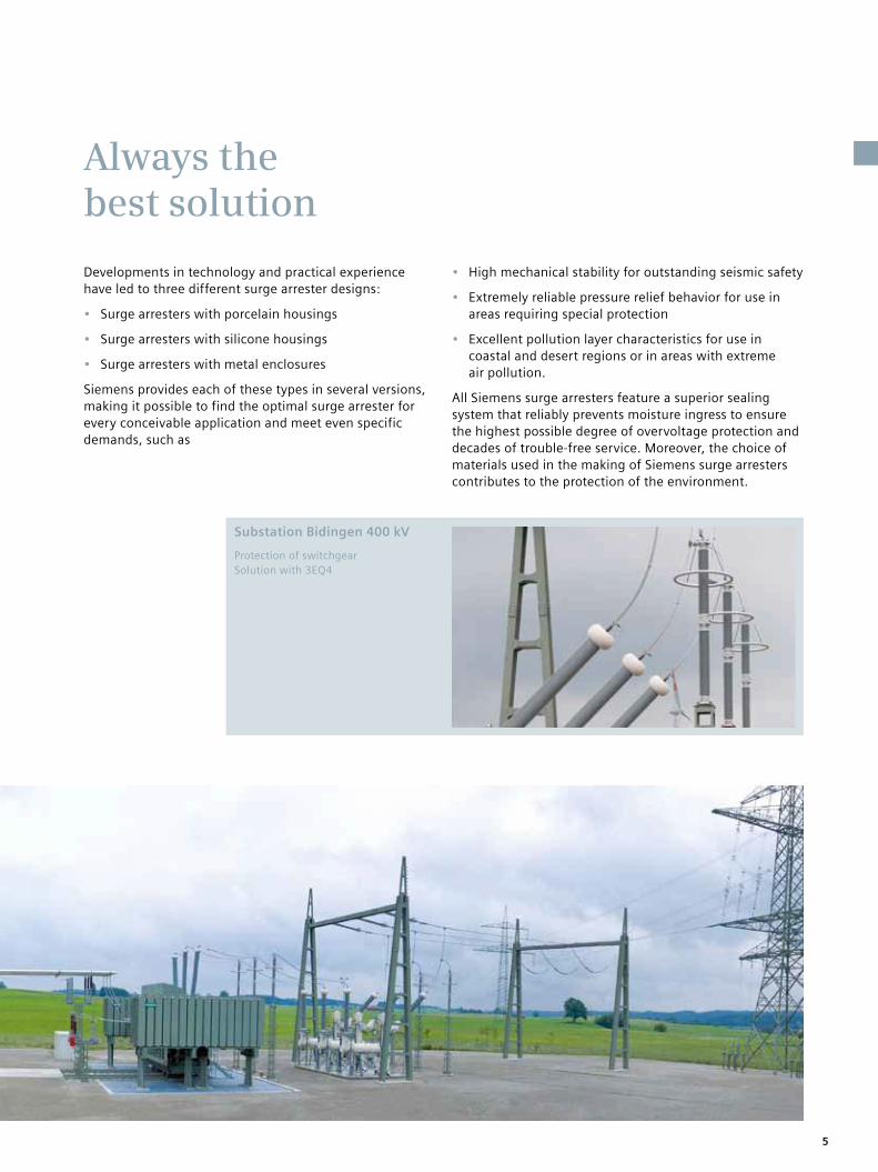
Substation Bidingen 400 kV
Protection of switchgearSolution with 3EQ4
5

History timeline Siemens is a pioneer in many fields of the electricity and digitization markets. Experience is most essential when it comes to reliability in medium- and high-voltage applications. Since 1925 Siemens has been manufac-turing high-voltage surge arresters up to duty cycle voltages of 1,200 kV – for standard and specialized appli-cations. Our permanent research and development and the concerted know-how in our factories give our surge arresters a leading edge in overvoltage protection. Our uncompromising quality ensures the long service life and reliability of each application.
1900
1847
The ten-employee company Telegraphen-Bauanstalt von Siemens & Halske (Telegraph Construction Company of Siemens & Halske) begins operation on October 12, 1847, in a back building in Berlin.
1971
Development of the first gas-insulated and metal- encapsulated surge arrester for gas-insulated switch-gear (GIS).
1925
Siemens begins developing surge arresters. The first devices are of the so-called cathode drop type.
1989
The 3EQ2 surge arrester for systems of up to 550 kV is one of the first high-volt-age surge arresters with composite polymer hollow core housing.
1866
Werner von Siemens dis-covers the dynamo-electric principle, which enables electricity to be put to prac-tical use. The dynamo can convert mechanical energy into electrical energy in an economical way. Its inven-tion lays the foundation for today’s world of electrical engineering.
1992
Continually pushing the envelope, Siemens devel-ops a high-voltage surge arrester with a composite polymer housing for sys-tems of up to 800 kV. It was originally developed as a suspended mounted HVDC valve arrester with several parallel metal oxide columns in a common housing.
1982
Siemens’ first gapless metal oxide arrester, a GIS surge arrester, is delivered for the 123 kV grid in Inchicore, a suburb of Dublin.
1963
The first surge arrester for systems of up to 550 kV is launched. The pulley wheel electrodes are replaced by ceramic-bonded shunt resistors and a series spark gap. The surge arrester comprises three columns in parallel and has a resistive-capacitive control.
6

As a pioneer in the field of silicone rubber insulation and one of the few suppliers with comprehensive in-house research and development capabilities in this technology, Siemens has been providing surge arresters with silicone rubber housing for more than 30 years and has gathered excellent service experi-ence from even the most severe climatic and environmental conditions. Today, silicone rubber is among the most widely used materials for high-voltage outdoor equipment.
2000 2010
2007
3EL2, the first line arrester for 550 kV applications, is delivered to Sochi, a city in Russia.
2011
Siemens introduces its new range of long rod insulators.2003
Completion of the first line arrester project, an order from KELAG, one of the leading energy service providers in Austria.
1998
The polymer-housed medi-um-voltage/distribution class arresters of the 3EK family, which features Cage Design™, a unique solution with direct silicone molding on the metal oxide varis-tors, is introduced.
2008
The first externally gapped line arrester (EGLA), which increases the reliability of a 144 kV overhead line, is supplied to the South Kore-an power provider KEPCO.
2006
Development of the 3EQ5, a new surge arrester concept with composite housing (type A) for extra high- voltage applications in 800 kV DC and 1,200 kV AC transmission systems.
2010
The world’s first 1,200 kV substation arrester with composite polymer hollow core technology is deliv-ered to Power Grid Corpora-tion of India.
2010
Siemens launches the arrester condition monitor, an innovative monitoring solution with unique features.
2000
Development of the first GIS arrester for systems of up to 800 kV.
7

MOVs: the core of Siemens surge arresters
The main task of an arrester is to protect equipment from the effects of over-voltages. During normal operation, an arrester should have no negative effect on the power system. Moreover, the arrester must be able to withstand typical surges without incurring any damage. Nonlinear resistors fulfill these require-ments thanks to the following properties:
• Low resistance during surges, so that overvoltages are limited
• High resistance during normal opera-tion to avoid negative effects on the power system
• Sufficient energy absorption capability for stable operation
With this kind of nonlinear resistor, there is only a small flow of current when continuous operating voltage is being applied. When there are surges, however, excess energy can quickly be removed from the power system by a high discharge current.
Nonlinear resistors made of metal oxide (MO) have proven especially suitable for this use. The nonlinearity of MO resistors is considerably high, which is why MO arresters do not need series gaps. Siemens has many years of experience with gapless MO arresters in low-voltage systems, distribution systems, and transmission systems.
Siemens metal oxide varistors (MOVs) provide a high switching surge energy rating and a very low protection level. This means they absorb a high amount of energy while avoiding thermal runaways. The MOVs are characterized by their high single impulse withstand rating. Siemens surge arresters are less prone to self-heating and consequent self-destruction, and they maintain their characteristics throughout their lifetime.
Power-frequency voltage vs. time (U-t)
characteristic (TOV)
p.u. Ur
t/s
1.30
1.25
1.20
1.15
1.10
1.05
1.00
0.95
0.90
0.85
0.80
1 10 100 1,000 10,000
Preheating to 60°C prior duty
8

Silicone rubber
As a pioneer in the field of silicone rubber insulation and one of the few suppliers with comprehensive in-house research and development capabilities in this technology, Siemens has been providing surge arresters with silicone rubber housing for more than 30 years and has gathered excellent service experience from even the most severe climatic and environmental conditions. Today, silicone rubber is among the most widely used materials for high-voltage outdoor equipment.
Siemens silicone rubber-housed surge arresters are polymer-housed arresters that use silicone rubber as the only insu-lating material. The exclusive use of sili-cone has proven to be the best solution in several studies: Silicone rubber is highly hydrophobic. While there are many polymeric materials with similar initial hydrophobic properties, most of them, such as EPDM alloy rubber, lose their hydrophobicity after a relatively short period. Only genuine silicone rubber as used by Siemens is capable of maintain-ing its hydrophobicity throughout its entire lifetime. This ensures the long ser-vice life of Siemens surge arresters with silicone rubber housing. Even the most severe ambient conditions, such as salt fog in coastal regions or dust-laden air causing serious contamination in an industrial area, cannot impair the hydro-phobicity of silicone rubber. This material property reliably prevents conductive moisture from forming on the arrester surface, thus averting surface currents and discharges. Moreover, genuine silicone is highly fire-retardant and self-extinguishing, and it is neither subject to erosion nor sensitive to UV radiation. This ensures the long-term stability of the housing material.
There are several characteristics that set the silicone elastomers used by Siemens apart from other organic insulating materials.
As a matter of principle, Siemens only uses HTV (high-temperature vulcanized) or LSR (liquid silicone rubber) silicone elastomers. These types of silicone help maintain the properties mentioned above.
The –Si–O– backbone of silicone rubber has a higher bonding energy than the –C–C– backbone of EPDM. Silicone rub-ber has a lower carbon proportion than EPDM. Consequently, silicone rubber boasts inherently better chemical and physical resistance, better UV resistance, and lower flammability than EPDM. Consider these facts:
• Silicone rubber is highly stable under the influence of ultraviolet radiation (sunlight), ozone, and nitrogen oxide. Its stability beats that of EPDM-based alloy rubbers.
• The hydrophobic performance of a sili-cone rubber surface remains excellent throughout the entire arrester service life, whereas EPDM-based alloy rub-bers lack this critical requirement.
• The hydrophobicity of silicone rubber returns after a corona discharge, which assures reliable long-term performance.
• The arcing resistance of silicone rub-ber is higher as compared to EPDM-based alloy rubbers.
• The flame-retardant properties of silicone rubber comply with IEC 60707 and UL94 V-0 (i.e. self-extinguishing, no burning drips, probe does not burn).
• Silicone rubber is resistant to all com-mon organic and nonorganic cleaning agents and solvents.
• Silicone rubber performs well in an ambient temperature range of –75 °F to +400 °F. No other polymeric material can beat silicone rubber.
Chalking
Cracking
Hydrophobic effect on Siemens 3EL surge arrester due to alignment of methyl groups in silicone polymers.
Characteristic damage on EPDM insulators due to natural UV radiation
Moisture
POWERSIL®
9

Porcelain
Siemens porcelain surge arresters feature a directional pressure relief device that ensures maximum protection in the case of an overload. Thanks to the excellent sealing of its surge arresters, Siemens has recorded decades of trouble-free service life without failures or moisture ingress.
Both ends of a porcelain surge arrester housing are equipped with aluminum flanges that are cemented to the housing. Sulfur cement is the first choice for this purpose. It has favorable mechanical prop-erties and also proves advantageous over Portland cement, which is quite common in the insulator industry. The main advan-tage of sulfur cement is that it can be
brought into contact with aluminum during manufacturing without causing any corrosion, and it can be quickly processed, since it almost reaches its full mechanical strength directly after application.
The design of the flanges and the end sections of the porcelain housings is key to the strength of the entire housing. This is why these parts of Siemens arresters are designed in a way that ensures that the cement joint is mechanically stronger than the porcelain itself. This enables making full use of the porcelain’s strength when specifying the permissible mechan-ical head loads of the arrester housing.
10

Station and intermediate class surge arresters
Siemens provides three surge arrester product families for standard and special AC applications from 3 kV up to 800 kV, which are described in this brochure:
• 3EL surge arresters with silicone housing, Cage Design™
• 3EQ surge arresters with silicone housing, composite hollow core design
• 3EP surge arresters with porcelain housing
11

Siemens’ Cage Design ensures high mechanical strength and safe overload performance. It is characterized by the use of silicone and fiberglass-reinforced plastic (FRP) rods as housing materials. Reliability is guaranteed by the direct molding of the silicone rubber onto the MO blocks and the FRP rods. This ensures the total embedding of all components free of enclosures and gaps, thus pre-venting any partial discharge or moisture ingress.
The MO blocks of 3EL surge arresters are enclosed by a cage made of FRP rods, which leads to a rigid, reinforced struc-ture ensuring high mechanical strength. The high tensile strength of the FRP rods is used to hold the arrester’s MO blocks in place tightly. This is why Cage Design arresters are among the mechanically strongest polymer arresters available on the market and at the same time ensure minimal use of material and very low weight. As the MO blocks are neither enclosed in a sealed mechanical shell nor wrapped in hard material, no excess pressure will develop in the case of an
overload or the extremely rare event of an arrester short circuit. The arc can escape directly through the soft silicone housing, and the ejection of internal parts that could damage other equipment nearby is prevented almost completely.
Long service life
Mechanically strong enough to meet common mechanical requirements and with sheds that are resistant to damage resulting from transport, installation, storms, earthquakes, and vandalism, 3EL surge arresters are perfectly suited for installations that demand low weight and indestructibility of the arrester.
Design features
End fittings
Cage of FRP rods
Metal oxide blocks
Silicone rubber sheds directly molded on metal oxide blocks and on end fittings
3EL silicone rubber surge arresters with Cage Design
12
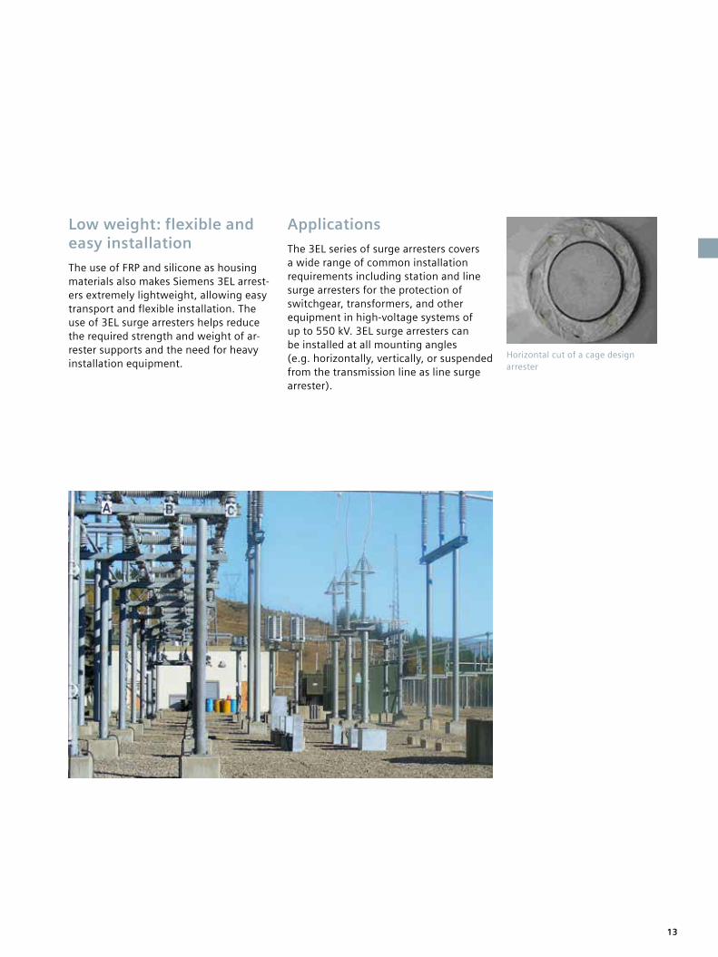
Low weight: flexible and easy installation
The use of FRP and silicone as housing materials also makes Siemens 3EL arrest-ers extremely lightweight, allowing easy transport and flexible installation. The use of 3EL surge arresters helps reduce the required strength and weight of ar-rester supports and the need for heavy installation equipment.
Applications
The 3EL series of surge arresters covers a wide range of common installation requirements including station and line surge arresters for the protection of switchgear, transformers, and other equipment in high-voltage systems of up to 550 kV. 3EL surge arresters can be installed at all mounting angles (e.g. horizontally, vertically, or suspended from the transmission line as line surge arrester).
Horizontal cut of a cage design arrester
13

3EQ silicone rubber surge arresters with composite hollow core design
Siemens’ innovative composite hollow core design uses silicone and a fiberglass reinforced plastic (FRP) tube as housing materials. The advantages of this design are more than compelling, as it offers the perfect combination of cost savings and safety for substations. The direct molding of the silicone rubber onto the FRP tube ensures reliability, while an excellent special sealing of the flanges at both ends of the surge arrester effec-tively prevents partial discharges and moisture ingress. The combination of silicone rubber and FRP tube also allows
an enormous withstand capability against mechanical forces. Hence, 3EQ surge arresters are the perfect choice for the replacement of existing post insula-tors in substations of up to 800 kV.
The composite hollow core design provides a very high degree of safety: In the case of an overload or the extremely rare case of an arrester short circuit, the arc escapes directly through directional pressure relief devices, internal parts are not ejected, and the housing does not break.
Design featuresDirectional
pressure relief device
Directional pressure relief
device
Cage of FRP rods
Metal oxide blocks
FRP tube
Silicone rubber sheds directly molded on FRP tube
End fittings with directional pressure
relief device and sealing system
14

A reliable, sturdy, and economic choiceSiemens 3EQ composite hollow core design surge arresters are virtually indestructible. While the composite hollow core design provides the highest possible mechanical strength and enables the support of high bending moments, the silicone rubber insulation is ideal for outdoor applications in severe envi-ronmental conditions. No matter how tough environmental and operating conditions may be, 3EQ arresters assure 100% reliable pressure relief performance and provide the ultimate in protection. They are shatterproof and retain at least 75 percent of their mechanical strength even after pressure relief, and they pro-vide the greatest stability, even during earthquakes.
Reduced space requirementsWhenever space is at a premium, 3EQ surge arresters can even be mounted directly over a transformer to support connectors without any danger to neigh-boring equipment. Their unique compos-ite hollow core design ensures maximum stability, even if an arrester should »blow out« after overloading. Pressure relief is absolutely reliable – there is no danger to equipment in the direct vicinity, no parts will be ejected, and the emerging arc will safely burn between the ends of the pressure relief device.
Longevity and reliabilityThe silicone rubber housings of 3EQ surge arresters provide the best possible long life performance for high-voltage surge arresters. They make use of all the advantages of vulcanizing silicone rubber sheds onto an FRP tube, providing enhanced safety and meeting every requirement.
ApplicationsSiemens 3EQ composite hollow core design surge arresters will go the extra mile. They meet highest mechanical demands and are ideally suited for chal-lenging environments, such as areas with heavy seismic activity or extremely high wind loads.
3EQ surge arresters boast a prolonged service life, because they are absolutely shatterproof and feature reliable overload performance with no hazardous splinters being ejected even under maximum pressure. These arresters can be installed close to costly system components. 3EQ composite hollow core design arresters are virtually indestructible during trans-portation, installation, storms, and earthquakes, and they are immune to vandalism.
Horizontal cut of a composite hollow core design arrester
15
3EP porcelain surge arresters
Siemens’ 3EP porcelain-housed surge arresters are the ideal choice for high mechanical performance requirements at voltage levels of up to 800 kV. With a seismic qualification of 0.5 g that is guaranteed up to 800 kV, they suit envi-ronments with even the most challenging mechanical requirements, such as heavy seismic activity and extremely high wind loads.
3EP surge arresters ensure maximum protection in an overload situation thanks to a specially designed directional pressure relief device. In the case of an overload or the extremely rare case of an arrester short circuit, the arc escapes easily through the pressure relief devices. No pressure is built up inside the arrester and no internal parts are ejected, which prevents damage to surrounding equipment.
The excellent sealing system of 3EP surge arresters prevents failures or moisture ingress and guarantees decades of trouble-free service. The use of nonporous sulfur cement instead of corrosive Port-land cement for bonding protects the MO blocks and prevents aging effects. The MO blocks of 3EP surge arresters are enclosed by a rigid, reinforced cage made of FRP rods. The high tensile strength of the FRP rods is used to hold the arrester’s MO blocks in place tightly.
ApplicationsThanks to their high degree of safety and reliability, Siemens 3EP porcelain-housed surge arresters can be installed in close proximity to costly system components. 3EP composite hollow core design arrest-ers are virtually indestructible during transportation, installation, storms, and earthquakes, and they are immune to vandalism.
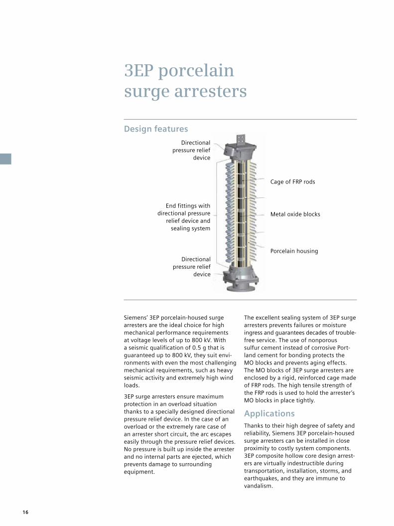
Design features
Directional pressure relief
device
Directional pressure relief
device
Cage of FRP rods
Metal oxide blocks
Porcelain housing
End fittings with directional pressure
relief device and sealing system
16

Standards and testing – reliability you can count on
TestsSiemens surge arresters have been designed and tested in compliance with the latest IEC 60099-4, IEEE C62.11, and GB 11032 standards. All type tests are performed by independent, PEHLA-certified laboratories; reports are avail-able on request. Please contact your Siemens representative for details.
Moreover, every single surge arrester that leaves the Siemens factory undergoes a routine test and is delivered with a routine test certificate.
Quality Assurance
Siemens meets all requirements of ISO 9001:2008, ISO 14002:2004, and BS OHSAS 18001:2007. All Siemens suppliers need to be certified according to ISO standards or will be audited by Siemens.
To maintain sustainable quality improve-ment, Siemens introduced corporate quality guidelines that contribute to each step of the quality process.
StandardizationThe aim of the IEEE’s Surge Protective Device Committee (SPDC) as well as the IEC’s Technical Committee 37 (TC 37) is the standardization of surge arrester testing and application.
The SPDC develops the standard IEEE C62.11 and the application guide IEEE C62.22, while the TC 37 develops the standards IEC 60099-4, IEC 60099-8 (EGLA), IEC 60099-9 (HVDC), and the application guide IEC 60099-5. Both committees include representatives of manufacturers, utilities, test field labs, and universities.
Siemens R&D experts are members of both bodies, thus playing an important role in the definition of the standards. They also share their expert knowledge in electrical power systems in CIGRE, the international council on large electric systems, which participates in the devel-opment of international standards.
The test field is certified by the »Deutsche Akkreditierungsstelle« (Germany’s national accreditation body) according to DIN EN ISO/IEC 17025
Test generator supplying both impulse voltages (1.2/50 µs and 250/250 µs) and impulse currents (8/20 µs and 30/60 µs)
UHV arrester prepared for testing in the HV test laboratory
17

Selection table
Fig. 1: Configuration procedure for an MO surge arrester
System Arrester Environment
ele
ctri
cal
me
chan
ical
Insulation level, safety margin, distance (protective zone)
Lightning current stress
Highest voltage of the system Us
Neutral earthing
Temporary overvoltages (TOV)
Ground flash density, magnitude of
lightning strikes
Duty cycle voltage Ur Cont. operating voltage Uc
Lightning impulse classifying current In
Active part specified
Energy class
LI protective level SI protective level
Cont. operating voltage Uc,min –> Duty cycle voltage Ur1
Duty cycle voltage Ur2
Energy (single-impulse withstand rating,
switching voltages)
Altitude of erection
Pollution
Seismic stress
Rated short-circuit current Is, mechanical loads MDCL resp. UMS
Housing
Leakage distance, shape of sheds
Length of housing, number of units, flashover distance (withstand voltages)
Diameter, material, length of units (number of units)Mechanical forces
(short-circuit current, bending and tensile
loads)
Short-circuit current
18
How to select a suitable surge arrester
This section describes the general approach to selecting typical arresters for overvoltage protection in high-voltage systems. For a detailed description of how to configure a surge arrester, please refer to the handbook Metal-Oxide Surge Arresters in High-Voltage Power Systems – Fundamentals.1
The requirements for a surge arrester emerge from two basic requirements: It should provide adequate protection with a sufficient safety margin, which means that overvol-tages at the device to be protected must always remain below its withstand voltage. Furthermore, the surge arrester should be dimensioned for stable continuous operation, which means that the arrester must remain electrically and thermally stable under all conditions while handling all long-term, temporary, and transient stress resulting from network operation.
These two requirements cannot be fulfilled independently. A reduction of the protective level automatically means a higher degree of specific electrical stress during continu-ous operation, and conversely, the continuous operating voltage of an arrester cannot be increased arbitrarily without raising its protective level as well. Both operating points are for a given type of MOV strictly associated with each other through the voltage-current (U-I-) characteris-tic curve.
The definition of the minimally required continuous oper-ating voltage, a factor which usually has a value of 1.25, helps achieve a duty cycle voltage Ur = 1.25 · Uc,min. This is the lowest necessary duty cycle voltage of the arrester. Table »Typical duty cycle voltages Ur for highest voltages of the system Us« on page 27 lists typically applied duty cycle voltages.
Solidly earthed neutral system: Uc,min ≥ Us/√3
Isolated or resonant earthed neutral system: Uc,min ≥ Us
Step 1: Selection of the maximum continuous operating voltage and the duty cycle voltage.
The first step is to define the minimally required continu-ous operating voltage Uc,min. This must be as high as the continuous phase-to-earth voltage of the system. Here, »continuously« applied voltage means every voltage that occurs within an uninterrupted period of more than 30 minutes. The type of neutral earthing of the system is decisive in determining the continuous operating voltage. In isolated or resonant earthed neutral systems, the volt-age of a healthy phase against ground takes on the value of the phase-to-phase voltage in the case of a one-phase earth fault (earth fault factor k = 1.73). Since resonant earthed neutral systems are operated quite commonly for time periods of more than 30 minutes in this condition, the continuous operating voltage of the arrester must, in this case, have the value of the highest voltage of the system, Us.
1 Volker Hinrichsen: »Metal-Oxide Surge Arresters in High-Voltage Power Systems«, 3rd edition, September 2012, Order No. E50001-G630-H197-X-4A00
19

Step 2: Selection of the lighting impulse classifying current In
The lighting impulse classifying current In serves to classify a surge arrester. From a technical point of view, it is calcu-lated from a typical maximum lightning current amplitude that can be expected in the substation, for which the insu-lation coordination is performed via the arrester’s light-ning protection level. This amplitude is calculated from the flashover voltage Ufo of the line insulators, the light-ning protection level Upl of the arresters, and the surge impedance Z of the line for Imax:
Step 3: Selection of protective levels
The protective characteristics of an arrester are most fre-quently assessed by means of its lightning impulse protec-tive level: It is assessed according to its discharge voltage while the lighting impulse classifying current is flowing. This usually means that a protective level equaling the standard lightning impulse withstand voltage of the device to be protected and divided by a factor of 1.4 is adequate for protection against lightning overvoltages.
Imax = (2·Ufo – Upl)/Z
Ufo = 2.1 MV Upl = 806 kV
Z = 350 Ω Imax = 9.7 kA
Example for a 420 kV system:
A 10 kA arrester, for instance, can readily withstand light-ning current impulses of higher amplitudes without severe damage.
Upl, 10kA, 8/20µs < BIL / 1.4
The selection of the electrical characteristics of the arrester is finished when the requirements regarding the protective levels of all mentioned current impulse stresses are fulfilled.
I / A
1400
0
600
200
1000
0.1 100.001
Example U-I-curve 550 kV network
50 Hz
U / kV
20
Step 5: Selection of the housingDielectric and mechanical requirements are generally taken into account when selecting the housing. The length, the leakage distance, and the material must be determined. The arrester characteristics determined by the housing are the rated short-circuit current Is, the Maxi-mum Design Cantilever Load-static (MDCL-static) for surge arresters with silicone housing and the Ultimate Mechani-cal Strength-static (UMS-static) for surge arresters with porcelain housing.
The minimal housing length first of all results from the demand that the MOV column (the active part) must fit. The length of this column is determined by the electrical data that were gathered during the selection steps taken up to that point. Generally speaking, further demands cause the housing lengths to be much greater than those of the active parts.
First of all, the clearance, which results from the with-stand voltage requirements, must be determined. Siemens takes care of the parameters »demand by MOV column« and »clearance« by stating the minimum required housing length.
Leakage distance requirements are, however, a much more frequent reason for longer housings. The shortest possible housing as a result of the length of the active part can normally be achieved only by designing for spe-cific leakage distances of less than 1 inch per kV duty cycle voltage. However, specific creepage distances of 1.25 inch/kV duty cycle voltage and more play an impor-tant role. In addition, there are environmental conditions, such as maritime and desert climates as well as heavy industrial pollution, that require the use of even longer leakage distance.
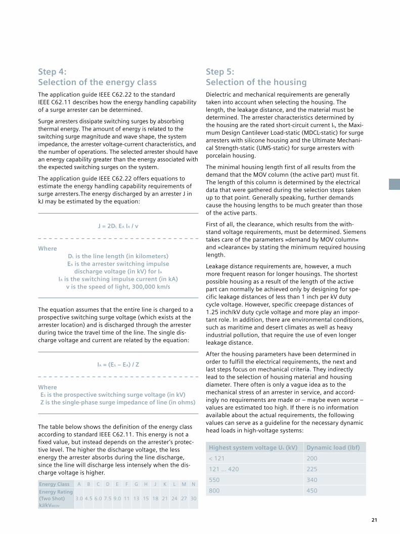
After the housing parameters have been determined in order to fulfill the electrical requirements, the next and last steps focus on mechanical criteria. They indirectly lead to the selection of housing material and housing diameter. There often is only a vague idea as to the mechanical stress of an arrester in service, and accord-ingly no requirements are made or – maybe even worse – values are estimated too high. If there is no information available about the actual requirements, the following values can serve as a guideline for the necessary dynamic head loads in high-voltage systems:
Step 4: Selection of the energy classThe application guide IEEE C62.22 to the standard IEEE C62.11 describes how the energy handling capability of a surge arrester can be determined.
Surge arresters dissipate switching surges by absorbing thermal energy. The amount of energy is related to the switching surge magnitude and wave shape, the system impedance, the arrester voltage-current characteristics, and the number of operations. The selected arrester should have an energy capability greater than the energy associated with the expected switching surges on the system.
The application guide IEEE C62.22 offers equations to estimate the energy handling capability requirements of surge arresters.The energy discharged by an arrester J in kJ may be estimated by the equation:
Highest system voltage Us (kV) Dynamic load (lbf)
< 121 200
121 … 420 225
550 340
800 450
J = 2DL EA IA / ν
IA = (ES − EA) / Z
DL is the line length (in kilometers) EA is the arrester switching impulse
discharge voltage (in kV) for IA IA is the switching impulse current (in kA)
v is the speed of light, 300,000 km/s
ES is the prospective switching surge voltage (in kV) Z is the single-phase surge impedance of line (in ohms)
Where
Where
The equation assumes that the entire line is charged to a prospective switching surge voltage (which exists at the arrester location) and is discharged through the arrester during twice the travel time of the line. The single dis-charge voltage and current are related by the equation:
The table below shows the definition of the energy class according to standard IEEE C62.11. This energy is not a fixed value, but instead depends on the arrester’s protec-tive level. The higher the discharge voltage, the less energy the arrester absorbs during the line discharge, since the line will discharge less intensely when the dis-charge voltage is higher.
Energy Class A B C D E F G H J K L M N
Energy Rating (Two Shot) kJ/kVMCOV
3.0 4.5 6.0 7.5 9.0 11 13 15 18 21 24 27 30
21

Glossary
Maximum Continuous Operating Voltage (MCOV, symbol Uc)
indicates the designated permissible root mean square value of the power frequency voltage that is allowed to be applied continuously between the arrester terminals.
Leakage (distance)
defines the distance between the metal end fittings, mea-sured along the housing surface. It is an important factor in the behavior of an insulator – or a device containing an insulator – in polluted conditions.
Highest voltage of a system (symbol Us)
indicates the root mean square value of the highest phase-to-phase operating voltage that occurs under nor-mal operating conditions at any time and at any point in the system.
Lightning impulse classifying current (symbol In)
indicates the peak value of a lightning current impulse used to classify an arrester.
Protective level
is the maximum value of an arrester’s discharge voltage at a standard current impulse. In this case, there is a differ-ence between the lightning impulse protective level (8/20 µs), the switching impulse protective level (30/60 µs), and the steep current impulse (1/2µs) protective level.
Rated short-circuit current (symbol Is)
indicates the root mean square value of the symmetrical highest short-circuit current that can flow after an arrester has been overloaded without causing violent shattering of the housing.
Duty cycle voltage (symbol Ur)
is the maximum permissible root mean square value of the power frequency voltage between the arrester termi-nals at which the arrester is designed to operate correctly
under temporary overvoltage conditions as established in the operating duty tests. Normally, the manufacturer specifies whether it can be applied to the arrester for a duration of 10 seconds (which corresponds to the value in the operating duty test) or 100 seconds. The duty cycle voltage is the reference parameter for determining the operating characteristics.
Discharge voltage
quantifies the voltage drop between the arrester’s terminals when a current impulse is injected. For current impulses in the shape and value of a standard test current impulse (lightning current impulse, switching current impulse, steep current impulse), the simultaneously occurring discharge voltages define the protective levels that are assigned to this current shape and value.
Maximum Design Cantilever Load-static (MDCL-static)
is a force perpendicular to the longitudinal axis of an arrester and allowed to be applied during service for long periods without causing any mechanical damage to the arrester.
Ultimate Mechanical Strength-static (UMS-static)
is a force perpendicular to the longitudinal axis of an arrester and allowed to be applied during service for long periods without causing any mechanical damage to the arrester.
Temporary overvoltage (TOV)
denominates the power frequency overvoltage that can occur for a duration of several tenths of a second to up to a few seconds, as a result of a switching operation or system failure. Its value depends on the type of neutral earthing in the system.
22

Siemens provides two solutions for line surge arresters:
Non-gapped line arresters (NGLA)
Non-gapped line surge arresters offer a high degree of mounting flexibility and operational reliability. Depending on the tower design and the arrangement of insulators and lines, these arresters can either be installed directly on the insula-tors or on the tower. Thanks to their high energy absorption capacity, non-gapped line arresters ensure a very high level of protection against overvoltages caused by lightning and network-generated switching impulse currents.
Siemens 3EL1, 3EL2, 3EL3, 3EL5 surge arresters are available as NGLA types.
Externally gapped line arresters (EGLA)
Siemens EGLA line surge arresters of the 3EV1, 3EV2, and 3EV5 series have an external spark gap placed in series that galvanically isolates the active part of the line surge arrester from the line voltage under normal conditions. In case of lightning, the spark gap is ignited and the dangerous overvoltage is safely dis-charged through the resulting arc. The active component limits the subsequent current to ensure that the arc is extin-guished within the first half-cycle of the operating current frequency.
The series varistor units (SVU) of the EGLA 3EV1, 3EV2, and 3EV5 product lines are based on the respective 3EL1, 3EL2, and 3EL5 product lines.
The use of surge arresters on hazardous stretches of a power line helps improve network protection and increases the reli-ability of the entire transmission system.
Offering a highly efficient combination of low weight, outstanding strength, and safety features, Siemens 3EL surge arrest-ers are ideally suited for this purpose.
Applications as line surge arresters
Refer to the brochure »Line surge arresters for increased system reliability« for a detailed overview of Siemens’ solutions for line surge arresters.
400 kV line in Bulgaria NGLA solution realized with 3EL2
550 kV line in ColombiaNGLA solution realized with 3EL2
23

Due to continuously growing worldwide power demand, more and more power networks are required to transmit higher loads – sometimes up to the limits of their capacity. This makes reliable, responsible network operation an increasingly difficult challenge. In many of today’s markets, transmission and distribution system operators are also liable for compensation in the case of power failures. And natural events like lightning can cripple entire networks. As a result, many network operators are seeking solutions to increase the reliabil-ity of their transmission systems. Equip-ment monitoring is a proven method for the recording of operating states and remaining service life, providing the operator with important asset manage-ment data and enabling the immediate assessment of a network’s overall state.
Early detection of relevant changes through efficient equipment monitoring
Surge arresters are highly reliable com ponents in power transmission and dis tribution systems. When operated in accordance with their specifications, their service life can reach up to 30 years with-out any maintenance. Nevertheless, over-loads that can cause arrester failure and even endanger the safety of the network may sometimes occur. Equipment moni-toring helps detect changes and faults at the earliest possible stage and supports security of supply on a whole new level. Siemens provides a complete line of mon-itoring devices with a variety of innova-tive functionalities that can be perfectly matched to customer requirements, ensuring that impending faults will be detected as early as possible and before security of supply is compromised.
24

Order code system
Data position 1 2 3 4 5 6 7 – 8 9 10 11 12 13 14 15 16 – Z
Order code n a a n n n n – n a a n n – n a a n – Z
Product line 3 E L 2
Rated voltage (kV) 0 9 6
Long duration current impulse, energy absorption capability 2
Application P
Housing size J
Line discharge class 3
Number of units 1
Form of sheds and color of housing 4
High-voltage terminal X
Nameplate H
Mounting 5
Accessories
Ordering exampleThe order code can be obtained through the following steps:
1. Select the product line from table »Main technical data« on page 26. Example: product line 3EL2
2. Select the duty cycle voltage and required energy rat-ing of the arrester using the »Ratings and specifications – Electrical characteristics« in the technical datasheet of the selected product line. Example: 3EL2 096-2P.3.-…
3. Select the required housing using the »Ratings and specifications – mechanical characteristics« in the technical datasheet of the selected product line. Example: for 3EL2 096-2P.3.-.… the minimum housing is »J«: + 3EL2 …-..J…, resulting in: 3EL2 096-2PJ31-…
4. Select the required terminal, nameplate, and mounting from the table »Order numbers« Example: 3EL2 096-2PJ31-4XH5. (4 = upright mounting, X = DIN/NEMA flat terminal, H = English ANSI nameplate, 5 = ø 10.0”, 3-hole grounded)
5. Select optional accessories from table »Optional accessories« on page 74 Example: D91 line clamp, resulting in 3EL2 096-2PJ31-4XH5-Z D91 D92
6. Select optional monitoring device from table »Monitoring devices« on page 75. Example: 3EX5 080-0 ACM basic
a: alphabeticaln: numerical
25
Product range
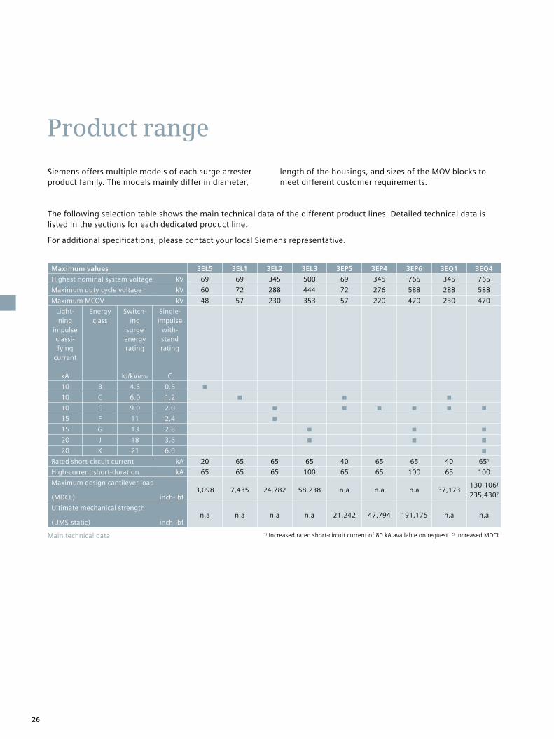
Siemens offers multiple models of each surge arrester product family. The models mainly differ in diameter,
length of the housings, and sizes of the MOV blocks to meet different customer requirements.
Maximum values 3EL5 3EL1 3EL2 3EL3 3EP5 3EP4 3EP6 3EQ1 3EQ4
Highest nominal system voltage kV 69 69 345 500 69 345 765 345 765
Maximum duty cycle voltage kV 60 72 288 444 72 276 588 288 588
Maximum MCOV kV 48 57 230 353 57 220 470 230 470
Light-ning
impulse classi-fying
current
kA
Energy class
Switch-ing
surge energy rating
kJ/kVMCOV
Single-impulse
with-stand rating
C
10 B 4.5 0.6
10 C 6.0 1.2
10 E 9.0 2.0
15 F 11 2.4
15 G 13 2.8
20 J 18 3.6
20 K 21 6.0
Rated short-circuit current kA 20 65 65 65 40 65 65 40 651
High-current short-duration kA 65 65 65 100 65 65 100 65 100
Maximum design cantilever load
(MDCL) inch-lbf3,098 7,435 24,782 58,238 n.a n.a n.a 37,173
130,106/
235,4302
Ultimate mechanical strength
(UMS-static) inch-lbfn.a n.a n.a n.a 21,242 47,794 191,175 n.a n.a
Main technical data 1) Increased rated short-circuit current of 80 kA available on request. 2) Increased MDCL.
The following selection table shows the main technical data of the different product lines. Detailed technical data is listed in the sections for each dedicated product line.
For additional specifications, please contact your local Siemens representative.
26

Typical duty cycle voltages Ur for system voltages Un according to IEEE C62.11.
System L-L voltage Un
kV
Four-wire multi-grounded neutral wye
Ur
kV
Three-wire low impedance grounded neutral circuit
Ur
kV
Three-wire high impedance grounded neutral circuit
Ur
kV
4.16 3 6 6
6.9 9
8.3 6 9
12 9 12
12.47 9 or 10 15
13.8 10 or 12 15 18
22.86 15 21
23 30
34.5 27 36
48.3 36 54
69 54 72 90
115 96 or 108
138 120
161 144
230 180
345 258
500 396 or 420
765 588
The table below shows an overview of the typical minimum duty cycle voltage for the surge arrester, depending on the system voltage and grounding of the system.
27

Protection of:
• Transformers
• Circuit breakers
• Generators
• Motors
• Capacitors
• Traction vehicles
• Bushings
• Switchgear
• Transmission lines
Maximum values 3EL5
Highest nominal system voltage kV 69
Maximum duty cycle voltage kV 60
Maximum MCOV kV 48
Lightning impulse classifying current kA 10
Energy class B
Switching surge energy rating kJ/kVMCOV 4.5
Single-impulse withstand rating C 0.6
Rated short-circuit current kA 20
High-current short-duration kA 65
Maximum design cantilever load (MDCL) inch-lbf 3,098
3EL5 Surge arrester with silicone rubber housing and Cage Design™
Technical datasheet
28 3EL5

3EL5 – order numbers
Data position 1 2 3 4 – 5 6 7 – 8 9 10 11 12 – 13 14 15 16
Order number 3 E L 5 x x x 0 P H 1 1 4 X H 5 – Z
Product line
Silicone rubber-housed surge arrester, cage design 3 E L 5
Duty cycle voltage in kV x x x
Energy class, single-impulse withstand rating, switching surge energy rating
Energy class B, Qs = 0.6 C, W = 4.5 kJ/kVMCOV 0 1
Application
Line surge arrester (For more details refer to catalog »Line surge arresters«) L
Phase surge arrester P
Housing size, number of units, leakage distance, height
Housing »B«, 1 unit, leakage distance 15 inch, height 7 inch B 1
Housing »C«, 1 unit, leakage distance 19 inch, height 8 inch C 1
Housing »D«, 1 unit, leakage distance 24 inch, height 9 inch D 1
Housing »E«, 1 unit, leakage distance 31 inch, height 11 inch E 1
Housing »F«, 1 unit, leakage distance 35 inch, height 12 inch F 1
Housing »H«, 1 unit, leakage distance 48 inch, height 16 inch H 1
Housing »J«, 1 unit, leakage distance 56 inch, height 19 inch J 1
Housing »K«, 1 unit, leakage distance 63 inch, height 20 inch K 1
Form of sheds and color of silicone rubber
Alternating sheds, gray silicone rubber, upright mounting 4
Alternating sheds, gray silicone rubber, suspended mounting 8
High-voltage terminal
NEMA 4-hole pad, 1.75”x1.75”, hot dip galvanized steel X
NEMA 4-hole pad, 1.75”x1.75”, stainless steel Y
Nameplate
English IEEE/ANSI H
Mounting
ø 10.0”, 3-hole insulated 1
ø 10.0”, 3-hole grounded 5
Customized solution 9
Accessories
Refer to table »Accessories for surge arresters« on page 74 – Z
293EL5
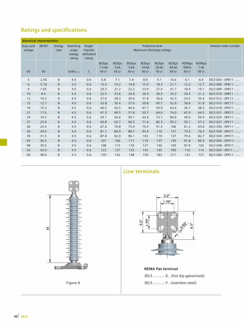
Ratings and specifications
Electrical characteristics
Duty cycle voltage
MCOV Energy class
Switching surge
energy rating
Single- impulse
withstand rating
Protective level Maximum discharge voltage
Arrester order number
kV
kV
kJ/kVmcov
C
8/20µs 1.5 kA kV cr
8/20µs 3 kA kV cr
8/20µs 5 kA kV cr
8/20µs 10 kA kV cr
8/20µs 20 kA kV cr
8/20µs 40 kA kV cr
45/90µs 500 A kV cr
45/90µs 1 kA kV cr
3 2.55 B 4.5 0.6 6.8 7.1 7.4 8.0 9.1 10.6 6.1 6.4 3EL5 003 - 0PB11 - ….
6 5.10 B 4.5 0.6 13.5 14.2 14.8 15.9 18.3 21.1 12.2 12.7 3EL5 006 - 0PB11 - ….
9 7.65 B 4.5 0.6 20.3 21.2 22.2 23.9 27.4 31.7 18.4 19.1 3EL5 009 - 0PB11 - ….
10 8.4 B 4.5 0.6 22.5 23.6 24.6 26.5 30.5 35.2 20.4 21.2 3EL5 010 - 0PB11 - ….
12 10.2 B 4.5 0.6 27.0 28.3 29.6 31.8 36.6 42.3 24.5 25.4 3EL5 012 - 0PC11 - ….
15 12.7 B 4.5 0.6 33.8 35.4 37.0 39.8 45.7 52.9 30.6 31.8 3EL5 015 - 0PC11 - ….
18 15.3 B 4.5 0.6 40.5 42.5 44.4 47.7 54.9 63.4 36.7 38.2 3EL5 018 - 0PD11 - ….
21 17.0 B 4.5 0.6 47.3 49.5 51.8 55.7 64.0 74.0 42.9 44.5 3EL5 021 - 0PD11 - ….
24 19.5 B 4.5 0.6 54.1 56.6 59.1 63.6 73.1 84.6 49.0 50.9 3EL5 024 - 0PE11 - ….
27 22.0 B 4.5 0.6 60.8 63.7 66.5 71.6 82.3 95.2 55.1 57.2 3EL5 027 - 0PE11 - ….
30 24.4 B 4.5 0.6 67.6 70.8 73.9 79.5 91.4 106 61.2 63.6 3EL5 030 - 0PF11 - ….
36 29.0 B 4.5 0.6 81.1 84.9 88.7 95.4 110 127 73.5 76.3 3EL5 036 - 0PH11 - ….
39 31.5 B 4.5 0.6 87.8 92.0 96.1 103 119 137 79.6 82.7 3EL5 039 - 0PH11 - ….
45 36.5 B 4.5 0.6 101 106 111 119 137 159 91.8 95.4 3EL5 045 - 0PH11 - ….
48 39.0 B 4.5 0.6 108 113 118 127 146 169 97.9 102 3EL5 048 - 0PH11 - ….
54 42.0 B 4.5 0.6 122 127 133 143 165 190 110 114 3EL5 054 - 0PJ11 - ….
60 48.0 B 4.5 0.6 135 142 148 159 183 211 122 127 3EL5 060 - 0PK11 - ….
Line terminals
Figure A
NEMA flat terminal
3EL5 …-…..-.X.. (hot dip galvanized)
3EL5 …-…..-.Y.. (stainless steel)
30 3EL5

Mechanical characteristics
Leakage distance
Height [H]
Recommended minimum clearances
Grading ring diameter
[D]
Cantilever strength
MDCL
Weight Figure
inch inch
To ground (ph-gnd)
inch
Between phases (ph-ph)
inch inch lbf lbs
15 7 1 2 - 463 6 A
15 7 1 2 - 463 6 A
15 7 1 2 - 463 6 A
15 7 2 3 - 463 7 A
19 8 2 3 - 393 7 A
19 8 3 4 - 393 7 A
24 9 4 5 - 328 8 A
24 9 4 5 - 328 8 A
31 11 5 6 - 291 9 A
31 11 6 7 - 291 9 A
35 12 7 9 - 262 10 A
48 16 8 10 - 197 11 A
48 16 9 11 - 197 12 A
48 16 12 13 - 197 13 A
48 16 12 13 - 197 13 A
56 19 16 18 - 167 14 A
63 20 16 18 - 154 15 A
Mounting
Insulated
3EL5 …-…..-…1
Grounded
3EL5 …-…..-…5
313EL5

3EL1 Surge arrester with silicone rubber housing and Cage Design™
Protection of:
• Transformers
• Circuit breakers
• Generators
• Motors
• Capacitors
• Traction vehicles
• Bushings
• Switchgear
• Transmission lines
Technical datasheet
Maximum values 3EL1
Highest nominal system voltage kV 69
Maximum duty cycle voltage kV 72
Maximum MCOV kV 57
Lightning impulse classifying current kA 10
Energy class C
Switching surge energy rating kJ/kVMCOV 6.0
Single-impulse withstand rating C 1.2
Rated short-circuit current kA 65
High-current short-duration kA 65
Maximum design cantilever load (MDCL) inch-lbf 7,435
32 3EL1

Data position 1 2 3 4 – 5 6 7 – 8 9 10 11 12 – 13 14 15 16
Order number 3 E L 1 x x x 1 P H 2 1 4 X H 5 – Z
Product line
Silicone rubber-housed surge arrester, cage design
3 E L 1
Duty cycle voltage in kV x x x
Energy class, single-impulse withstand rating, switching surge energy rating
Energy class C, Qs = 1.2 C, W = 6.0 kJ/kVMCOV 1 2
Application
Line surge arrester (For more details refer to catalog »Line surge arresters«) L
Phase surge arrester P
Housing size, number of units, leakage distance, height
Housing »C«, 1 unit, leakage distance 35 inch, height 12 inch C 1
Housing »E«, 1 unit, leakage distance 55 inch, height 18 inch E 1
Housing »H«, 1 unit, leakage distance 81 inch, height 24 inch H 1
Housing »K«, 1 unit, leakage distance 121 inch, height 35 inch K 1
Housing »E+H«, 2 units, leakage distance 136 inch, height 42 inch N 2
Housing »2xH«, 2 units, leakage distance 161 inch, height 49 inch H 2
Housing »E+K«, 2 units, leakage distance 176 inch, height 53 inch P 2
Housing »H+K«, 2 units, leakage distance 202 inch, height 60 inch Q 2
Housing »2xK«, 2 units, leakage distance 242 inch, height 71 inch K 2
Form of sheds and color of silicone rubber
Alternating sheds, gray silicone rubber, upright mounting 4
Alternating sheds, gray silicone rubber, suspended mounting 8
High-voltage terminal
NEMA 4-hole pad, 1.75”x1.75”, hot dip galvanized steel X
NEMA 4-hole pad, 1.75”x1.75”, stainless steel Y
Nameplate
English IEEE/ANSI H
Mounting
ø 10.0”, 3-hole insulated 1
ø 10.0”, 3-hole grounded 5
Customized solution 9
Accessories
Refer to table »Accessories for surge arresters« on page 74 – Z
3EL1 – order numbers
333EL1
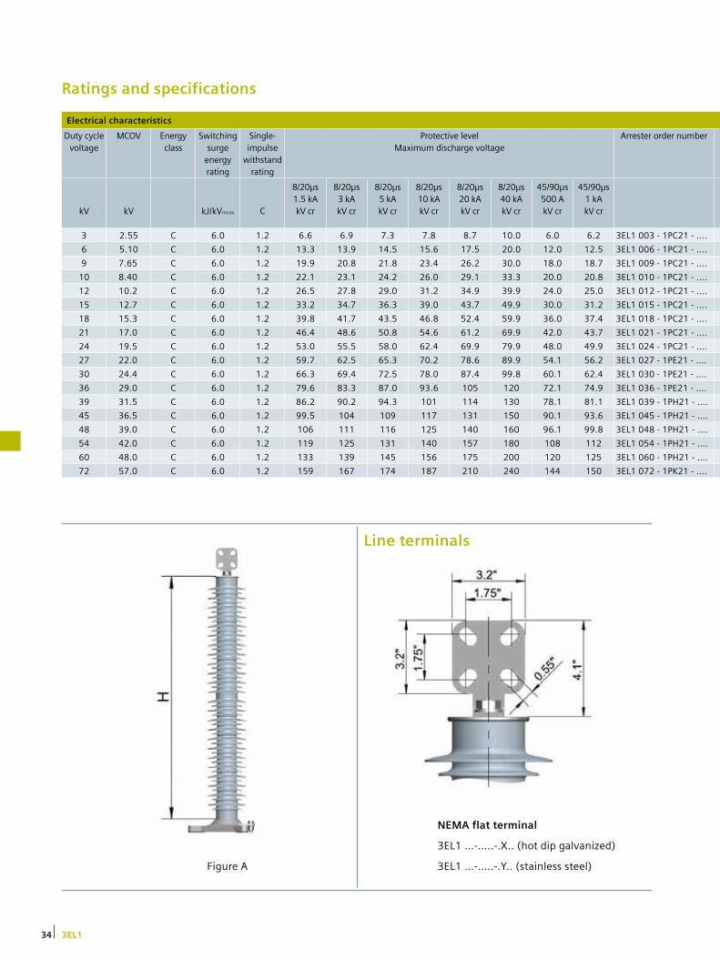
Ratings and specifications
Electrical characteristics
Duty cycle voltage
MCOV Energy class
Switching surge
energy rating
Single- impulse
withstand rating
Protective level Maximum discharge voltage
Arrester order number
kV
kV
kJ/kVmcov
C
8/20µs 1.5 kA kV cr
8/20µs 3 kA kV cr
8/20µs 5 kA kV cr
8/20µs 10 kA kV cr
8/20µs 20 kA kV cr
8/20µs 40 kA kV cr
45/90µs 500 A kV cr
45/90µs 1 kA kV cr
3 2.55 C 6.0 1.2 6.6 6.9 7.3 7.8 8.7 10.0 6.0 6.2 3EL1 003 - 1PC21 - ….
6 5.10 C 6.0 1.2 13.3 13.9 14.5 15.6 17.5 20.0 12.0 12.5 3EL1 006 - 1PC21 - ….
9 7.65 C 6.0 1.2 19.9 20.8 21.8 23.4 26.2 30.0 18.0 18.7 3EL1 009 - 1PC21 - ….
10 8.40 C 6.0 1.2 22.1 23.1 24.2 26.0 29.1 33.3 20.0 20.8 3EL1 010 - 1PC21 - ….
12 10.2 C 6.0 1.2 26.5 27.8 29.0 31.2 34.9 39.9 24.0 25.0 3EL1 012 - 1PC21 - ….
15 12.7 C 6.0 1.2 33.2 34.7 36.3 39.0 43.7 49.9 30.0 31.2 3EL1 015 - 1PC21 - ….
18 15.3 C 6.0 1.2 39.8 41.7 43.5 46.8 52.4 59.9 36.0 37.4 3EL1 018 - 1PC21 - ….
21 17.0 C 6.0 1.2 46.4 48.6 50.8 54.6 61.2 69.9 42.0 43.7 3EL1 021 - 1PC21 - ….
24 19.5 C 6.0 1.2 53.0 55.5 58.0 62.4 69.9 79.9 48.0 49.9 3EL1 024 - 1PC21 - ….
27 22.0 C 6.0 1.2 59.7 62.5 65.3 70.2 78.6 89.9 54.1 56.2 3EL1 027 - 1PE21 - ….
30 24.4 C 6.0 1.2 66.3 69.4 72.5 78.0 87.4 99.8 60.1 62.4 3EL1 030 - 1PE21 - ….
36 29.0 C 6.0 1.2 79.6 83.3 87.0 93.6 105 120 72.1 74.9 3EL1 036 - 1PE21 - ….
39 31.5 C 6.0 1.2 86.2 90.2 94.3 101 114 130 78.1 81.1 3EL1 039 - 1PH21 - ….
45 36.5 C 6.0 1.2 99.5 104 109 117 131 150 90.1 93.6 3EL1 045 - 1PH21 - ….
48 39.0 C 6.0 1.2 106 111 116 125 140 160 96.1 99.8 3EL1 048 - 1PH21 - ….
54 42.0 C 6.0 1.2 119 125 131 140 157 180 108 112 3EL1 054 - 1PH21 - ….
60 48.0 C 6.0 1.2 133 139 145 156 175 200 120 125 3EL1 060 - 1PH21 - ….
72 57.0 C 6.0 1.2 159 167 174 187 210 240 144 150 3EL1 072 - 1PK21 - ….
Figure A
Line terminals
NEMA flat terminal
3EL1 …-…..-.X.. (hot dip galvanized)
3EL1 …-…..-.Y.. (stainless steel)
34 3EL1

Mechanical characteristics
Leakage distance
Height [H]
Recommended minimum clearances
Grading ring diameter
[D]
Cantilever strength
MDCL
Weight Figure
inch inch
To ground (ph-gnd)
inch
Between phases (ph-ph)
inch inch lbf lbs
35 12 1 2 - 619 13 A
35 12 1 2 - 619 13 A
35 12 1 2 - 619 14 A
35 12 2 3 - 619 14 A
35 12 2 3 - 619 14 A
35 12 2 3 - 619 15 A
35 12 3 4 - 619 15 A
35 12 4 5 - 619 15 A
35 12 5 6 - 619 15 A
55 18 6 7 - 424 19 A
55 18 6 7 - 424 19 A
55 18 8 10 - 424 19 A
81 24 9 11 - 305 23 A
81 24 10 12 - 305 23 A
81 24 12 13 - 305 23 A
81 24 16 18 - 305 24 A
81 24 16 18 - 305 25 A
121 35 21 24 - 210 29 A
Mounting
Insulated
3EL1 …-…..-…1
Grounded
3EL1 …-…..-…5
353EL1

3EL2 Surge arrester with silicone rubber housing and Cage Design™
Maximum values 3EL2 3EL2
Highest nominal system voltage kV 345 345
Maximum duty cycle voltage kV 288 288
Maximum MCOV kV 230 230
Lightning impulse classifying current kA 10 15
Energy class E F
Switching surge energy rating kJ/kVMCOV 9.0 11
Single-impulse withstand rating C 2.0 2.4
Rated short-circuit current kA 65 65
High-current short-duration kA 65 65
Maximum design cantilever load (MDCL) inch-lbf 24,782 24,782
Technical datasheet
Protection of:
• Transformers
• Circuit breakers
• Generators
• Motors
• Capacitors
• Traction vehicles
• Bushings
• Switchgear
• Transmission lines
36 3EL2

Data position 1 2 3 4 – 5 6 7 – 8 9 10 11 12 – 13 14 15 16
Order number 3 E L 2 x x x 2 P M 3 1 4 X H 5 – Z
Product line
Silicone rubber-housed surge arrester, cage design
3 E L 2
Duty cycle voltage in kV x x x
Energy class, single-impulse withstand rating, switching surge energy rating
Energy class E, Qs = 2.0 C, W = 9.0 kJ/kVMCOV 2 3
Energy class F, Qs = 2.4 C, W = 11.0 kJ/kVMCOV 6 4
Application
Line surge arrester (For more details refer to catalog »Line surge arresters«) L
Phase surge arrester P
Housing size, number of units, leakage distance, height
Housing »C«, 1 unit, leakage distance 58 inch, height 19 inch C 1
Housing »F«, 1 unit, leakage distance 92 inch, height 28 inch F 1
Housing »J«, 1 unit, leakage distance 150 inch, height 42 inch J 1
Housing »M«, 1 unit, leakage distance 177 inch, height 49 inch M 1
Housing »C+J«, 2 units, leakage distance 208 inch, height 61 inch P 2
Housing »F+J«, 2 units, leakage distance 243 inch, height 70 inch Q 2
Housing »F+M«, 2 units, leakage distance 269 inch, height 77 inch R 2
Housing »2xJ«, 2 units, leakage distance 301 inch, height 84 inch J 2
Housing »J+M«, 2 units, leakage distance 327 inch, height 91 inch W 2
Housing »2xM«, 2 units, leakage distance 354 inch, height 98 inch M 2
Form of sheds and color of silicone rubber
Alternating sheds, gray silicone rubber, upright mounting 4
Alternating sheds, gray silicone rubber, suspended mounting 8
High-voltage terminal
NEMA 4-hole pad, 1.75”x1.75”, hot dip galvanized steel X
NEMA 4-hole pad, 1.75”x1.75”, stainless steel Y
Nameplate
English IEEE/ANSI H
Mounting
ø 10.0”, 3-hole insulated 1
ø 10.0”, 3-hole grounded 5
Customized solution 9
Accessories
Refer to table »Accessories for surge arresters« on page 74 – Z
3EL2 – order numbers
373EL2

Ratings and specifications
Electrical characteristics
Duty cycle voltage
MCOV Energy class
Switching surge
energy rating
Single- impulse
withstand rating
Protective level Maximum discharge voltage
Arrester order number
kV
kV
kJ/kVmcov
C
8/20µs 1.5 kA kV cr
8/20µs 3 kA kV cr
8/20µs 5 kA kV cr
8/20µs 10 kA kV cr
8/20µs 20 kA kV cr
8/20µs 40 kA kV cr
45/90µs 500 A kV cr
45/90µs 1 kA kV cr
3 2.55 E 9.0 2.0 6.2 6.5 6.8 7.2 8.0 9.1 5.8 5.9 3EL2 003 - 2PC31 - ….
6 5.10 E 9.0 2.0 12.4 13.0 13.5 14.4 16.0 18.1 11.5 11.8 3EL2 006 - 2PC31 - ….
9 7.65 E 9.0 2.0 18.6 19.4 20.3 21.6 24.0 27.2 17.3 17.7 3EL2 009 - 2PC31 - ….
10 8.4 E 9.0 2.0 20.6 21.6 22.6 24.0 26.6 30.2 19.2 19.7 3EL2 010 - 2PC31 - ….
12 10.2 E 9.0 2.0 24.8 25.9 27.1 28.8 32.0 36.3 23.0 23.6 3EL2 012 - 2PC31 - ….
15 12.7 E 9.0 2.0 31.0 32.4 33.8 36.0 40.0 45.4 28.8 29.5 3EL2 015 - 2PC31 - ….
18 15.3 E 9.0 2.0 37.2 38.9 40.6 43.2 48.0 54.4 34.6 35.4 3EL2 018 - 2PC31 - ….
21 17.0 E 9.0 2.0 43.3 45.4 47.4 50.4 55.9 63.5 40.3 41.3 3EL2 021 - 2PC31 - ….
24 19.5 E 9.0 2.0 49.5 51.8 54.1 57.6 63.9 72.6 46.1 47.2 3EL2 024 - 2PC31 - ….
27 22.0 E 9.0 2.0 55.7 58.3 60.9 64.8 71.9 81.6 51.8 53.1 3EL2 027 - 2PC31 - ….
30 24.4 E 9.0 2.0 61.9 64.8 67.7 72.0 79.9 90.7 57.6 59.0 3EL2 030 - 2PC31 - ….
36 29.0 E 9.0 2.0 74.3 77.8 81.2 86.4 95.9 109 69.1 70.8 3EL2 036 - 2PC31 - ….
39 31.5 E 9.0 2.0 80.5 84.2 88.0 93.6 104 118 74.9 76.8 3EL2 039 - 2PC31 - ….
45 36.5 E 9.0 2.0 92.9 97.2 102 108 120 136 86.4 88.6 3EL2 045 - 2PF31 - ….
48 39.0 E 9.0 2.0 99.1 104 108 115 128 145 92.2 94.5 3EL2 048 - 2PF31 - ….
54 42.0 E 9.0 2.0 111 117 122 130 144 163 104 106 3EL2 054 - 2PF31 - ….
60 48.0 E 9.0 2.0 124 130 135 144 160 181 115 118 3EL2 060 - 2PF31 - ….
72 57.0 E 9.0 2.0 149 156 162 173 192 218 138 142 3EL2 072 - 2PF31 - ….
90 70.0 E 9.0 2.0 186 194 203 216 240 272 173 177 3EL2 090 - 2PJ31 - ….
96 76.0 E 9.0 2.0 198 207 217 230 256 290 184 189 3EL2 096 - 2PJ31 - ….
96 76.0 F 11.0 2.4 192 199 208 221 243 265 179 183 3EL2 096 - 6PJ41 - ….
108 84.0 E 9.0 2.0 223 233 244 259 288 327 207 213 3EL2 108 - 2PJ31 - ….
111 88.0 E 9.0 2.0 229 240 250 266 296 336 213 218 3EL2 111 - 2PJ31 - ….
120 98.0 E 9.0 2.0 248 259 271 288 320 363 230 236 3EL2 120 - 2PJ31 - ….
132 106 E 9.0 2.0 272 285 298 317 352 399 253 260 3EL2 132 - 2PM31 - ….
144 115 E 9.0 2.0 297 311 325 346 384 435 276 283 3EL2 144 - 2PM31 - ….
168 131 E 9.0 2.0 347 363 379 403 448 508 323 331 3EL2 168 - 2PQ32 - ….
172 140 E 9.0 2.0 355 372 388 413 458 520 330 338 3EL2 172 - 2PQ32 - ….
180 144 E 9.0 2.0 372 389 406 432 480 544 346 354 3EL2 180 - 2PQ32 - ….
192 152 E 9.0 2.0 396 415 433 461 511 581 369 378 3EL2 192 - 2PQ32 - ….
192 152 E 9.0 2.0 396 415 433 461 511 581 369 378 3EL2 192 - 2PJ32 - ….
192 152 F 11.0 2.4 384 397 415 442 486 530 358 367 3EL2 192 - 6PQ42 - ….
192 152 F 11.0 2.4 384 397 415 442 486 530 358 367 3EL2 192 - 6PJ42 - ….
228 180 E 9.0 2.0 471 492 514 547 607 689 438 449 3EL2 228 - 2PJ32 - ….
240 190 E 9.0 2.0 495 518 541 576 639 726 461 472 3EL2 240 - 2PJ32 - ….
258 209 E 9.0 2.0 533 557 582 619 687 780 495 508 3EL2 258 - 2PW32 - ….
258 209 E 9.0 2.0 533 557 582 619 687 780 495 508 3EL2 258 - 2PM32 - ….
264 212 E 9.0 2.0 545 570 596 634 703 798 507 520 3EL2 264 - 2PM32 - ….
264 212 F 11.0 2.4 528 546 571 607 668 729 492 504 3EL2 264 - 6PW42 - ….
276 220 E 9.0 2.0 570 596 623 662 735 835 530 543 3EL2 276 - 2PM32 - ….
276 220 F 11.0 2.4 552 571 597 635 698 762 514 527 3EL2 276 - 6PM42 - ….
288 230 F 11.0 2.4 576 596 623 662 729 795 537 550 3EL2 288 - 6PM42 - ….
38 3EL2

Mechanical characteristics
Leakage distance
Height [H]
Recommended minimum clearances
Grading ring diameter
[D]
Cantilever strength
MDCL
Weight Figure
inch inch
To ground (ph-gnd)
inch
Between phases (ph-ph)
inch inch lbf lbs
58 19 1 2 - 1,306 32 A
58 19 1 2 - 1,306 32 A
58 19 1 2 - 1,306 32 A
58 19 1 2 - 1,306 32 A
58 19 2 3 - 1,306 33 A
58 19 2 3 - 1,306 33 A
58 19 3 4 - 1,306 35 A
58 19 4 5 - 1,306 35 A
58 19 4 5 - 1,306 36 A
58 19 5 6 - 1,306 36 A
58 19 6 7 - 1,306 36 A
58 19 7 9 - 1,306 37 A
58 19 8 10 - 1,306 38 A
92 28 9 11 - 893 45 A
92 28 10 12 - 893 45 A
92 28 12 13 - 893 47 A
92 28 16 18 - 893 48 A
92 28 16 18 - 893 49 A
150 42 21 24 - 593 62 A
150 42 31 34 - 593 63 A
150 42 21 24 - 593 64 A
150 42 31 34 - 593 66 A
150 42 31 34 - 593 66 A
150 42 31 34 - 593 67 A
177 49 50 56 - 508 74 A
177 49 50 56 - 508 76 A
243 70 50 56 - 356 104 B
243 70 50 56 - 356 104 B
243 70 50 56 - 356 105 B
243 70 50 56 - 356 108 B
301 84 50 56 - 296 108 B
243 70 50 56 - 356 110 B
301 84 50 56 - 296 110 B
301 84 59 66 - 296 123 B
301 84 59 66 - 296 126 B
327 91 68 77 24 273 134 C
354 98 68 77 31 254 140 C
354 98 68 77 31 254 140 C
327 91 68 77 24 273 140 C
354 98 68 77 31 254 142 C
354 98 68 77 31 254 146 C
354 98 68 77 31 254 149 C
393EL2

Figure A Figure B Figure C
40 3EL2

Mounting
Insulated
3EL2 …-…..-…1
NEMA flat terminal
3EL2 …-…..-.X.. (hot dip galvanized)
3EL2 …-…..-.Y.. (stainless steel)
Grounded
3EL2 …-…..-…5
Line terminals
413EL2

Maximum values 3EL3 3EL3
Highest nominal system voltage kV 500 500
Maximum duty cycle voltage kV 444 444
Maximum MCOV kV 353 353
Lightning impulse classifying current kA 15 20
Energy class G J
Switching surge energy rating kJ/kVMCOV 13 18
Single-impulse withstand rating C 2.8 3.6
Rated short-circuit current kA 65 65
High-current short-duration kA 100 100
Maximum design cantilever load (MDCL) inch-lbf 58,238 58,238
3EL3 Surge arrester with silicone rubber housing and Cage Design™
Technical datasheet
Protection of:
• Transformers
• Circuit breakers
• Generators
• Motors
• Capacitors
• Bushings
• Switchgear
• Transmission lines
42 3EL3

Data position 1 2 3 4 – 5 6 7 – 8 9 10 11 12 – 13 14 15 16
Order number 3 E L 3 x x x 4 P J 4 1 4 X H 5 – Z
Product line
Silicone rubber-housed surge arrester, cage design
3 E L 3
Duty cycle voltage in kV x x x
Energy class, single-impulse withstand rating, switching surge energy rating
Energy class G, Qs = 2.8 C, W = 13.0 kJ/kVMCOV 4 4
Energy class J, Qs = 3.6 C, W = 18.0 kJ/kVMCOV 4 5
Application
Line surge arrester (For more details refer to catalog »Line surge arresters«) L
Phase surge arrester P
Housing size, number of units, leakage distance, height
Housing »F«, 1 unit, leakage distance 97 inch, height 29 inch F 1
Housing »G«, 1 unit, leakage distance 113 inch, height 33 inch G 1
Housing »H«, 1 unit, leakage distance 128 inch, height 36 inch H 1
Housing »J«, 1 unit, leakage distance 143 inch, height 40 inch J 1
Housing »K«, 1 unit, leakage distance 159 inch, height 43 inch K 1
Housing »L«, 1 unit, leakage distance 174 inch, height 47 inch L 1
Housing »M«, 1 unit, leakage distance 189 inch, height 50 inch M 1
Housing »2xG«, 2 units, leakage distance 226 inch, height 66 inch G 2
Housing »2xH«, 2 units, leakage distance 256 inch, height 73 inch H 2
Housing »2xJ«, 2 units, leakage distance 287 inch, height 80 inch J 2
Housing »2xK«, 2 units, leakage distance 317 inch, height 87 inch K 2
Housing »2xL«, 2 units, leakage distance 348 inch, height 94 inch L 2
Housing »2xM«, 2 units, leakage distance 378 inch, height 101 inch M 2
Housing »3xJ«, 3 units, leakage distance 430 inch, height 120 inch J 3
Housing »3xK«, 3 units, leakage distance 476 inch, height 130 inch K 3
Housing »3xL«, 3 units, leakage distance 522 inch, height 141 inch L 3
Housing »3xM«, 3 units, leakage distance 568 inch, height 151 inch M 3
Form of sheds and color of silicone rubber
Alternating sheds, gray silicone rubber, upright mounting 4
Alternating sheds, gray silicone rubber, suspended mounting 8
High-voltage terminal
NEMA 4-hole pad, 1.75”x1.75”, hot dip galvanized steel X
NEMA 4-hole pad, 1.75”x1.75”, stainless steel Y
Nameplate
English IEEE/ANSI H
Mounting
ø 10.0”, 3-hole grounded 5
ø 10.0”, 3-hole insulated 7
Customized solution 9
Accessories
Refer to table »Accessories for surge arresters« on page 74 – Z
3EL3 – order numbers
433EL3

Ratings and specifications
Electrical characteristics
Duty cycle voltage
MCOV Energy class
Switching surge
energy rating
Single- impulse
withstand rating
Protective level Maximum discharge voltage
Arrester order number
kV
kV
kJ/kVmcov
C
8/20µs 1.5 kA kV cr
8/20µs 3 kA kV cr
8/20µs 5 kA kV cr
8/20µs 10 kA kV cr
8/20µs 20 kA kV cr
8/20µs 40 kA kV cr
45/90µs 1 kA kV cr
45/90µs 2 kA kV cr
258 209 G 13.0 2.8 511 528 549 581 633 691 496 511 3EL3 258 - 4PK42 - ….
258 209 J 18.0 3.6 511 528 549 581 633 691 496 511 3EL3 258 - 4PK52 - ….
264 212 G 13.0 2.8 523 541 561 594 647 707 508 523 3EL3 264 - 4PK42 - ….
264 212 J 18.0 3.6 523 541 561 594 647 707 508 523 3EL3 264 - 4PL52 - ….
276 220 G 13.0 2.8 546 565 587 621 677 739 531 546 3EL3 276 - 4PL42 - ….
276 220 J 18.0 3.6 546 565 587 621 677 739 531 546 3EL3 276 - 4PL52 - ….
288 230 G 13.0 2.8 570 590 612 648 706 771 554 570 3EL3 288 - 4PL42 - ….
288 230 J 18.0 3.6 570 590 612 648 706 771 554 570 3EL3 288 - 4PL52 - ….
294 235 G 13.0 2.8 582 602 625 662 721 787 566 582 3EL3 294 - 4PL42 - ….
294 235 J 18.0 3.6 582 602 625 662 721 787 566 582 3EL3 294 - 4PM52 - ….
312 245 G 13.0 2.8 618 639 663 702 765 835 600 618 3EL3 312 - 4PJ43 - ….
312 245 J 18.0 3.6 618 639 663 702 765 835 600 618 3EL3 312 - 4PJ53 - ….
396 318 G 13.0 2.8 784 811 842 891 971 1,060 762 784 3EL3 396 - 4PL43 - ….
396 318 J 18.0 3.6 784 811 842 891 971 1,060 762 784 3EL3 396 - 4PL53 - ….
420 335 G 13.0 2.8 832 860 893 945 1,030 1,125 808 832 3EL3 420 - 4PK44 - ….
420 335 J 18.0 3.6 832 860 893 945 1,030 1,125 808 832 3EL3 420 - 4PK54 - ….
444 353 G 13.0 2.8 879 909 944 999 1,089 1,189 854 879 3EL3 444 - 4PK44 - ….
444 353 J 18.0 3.6 879 909 944 999 1,089 1,189 854 879 3EL3 444 - 4PK54 - ….
44 3EL3

Mechanical characteristics
Leakage distance
Height [H]
Recommended minimum clearances
Grading ring diameter
[D]
Cantilever strength
MDCL
Weight Figure
inch inch
To ground (ph-gnd)
inch
Between phases (ph-ph)
inch inch lbf lbs
317 87 59 66 24 670 216 C
317 87 59 66 24 670 222 C
317 87 59 66 24 670 218 C
348 94 59 66 24 620 230 C
348 94 68 77 24 620 227 C
348 94 68 77 24 620 234 C
348 94 68 77 24 620 231 C
348 94 68 77 24 620 238 C
348 94 68 77 24 620 234 C
378 101 68 77 31 577 245 C
430 120 76 85 31 486 283 D
430 120 76 85 31 486 291 D
522 141 97 111 39 413 341 D
522 141 97 111 39 413 351 D
634 174 97 111 59 335 409 E
634 174 97 111 59 335 420 E
634 174 109 125 59 335 418 E
634 174 109 125 59 335 428 E
453EL3

Figure D Figure EFigure A Figure B Figure C
46 3EL3

NEMA flat terminal
3EL3 …-…..-.X.. (hot dip galvanized)
3EL3 …-…..-.Y.. (stainless steel)
Line terminals
Mounting
Insulated
3EL3 …-…..-…7
Grounded
3EL3 …-…..-…5
473EL3
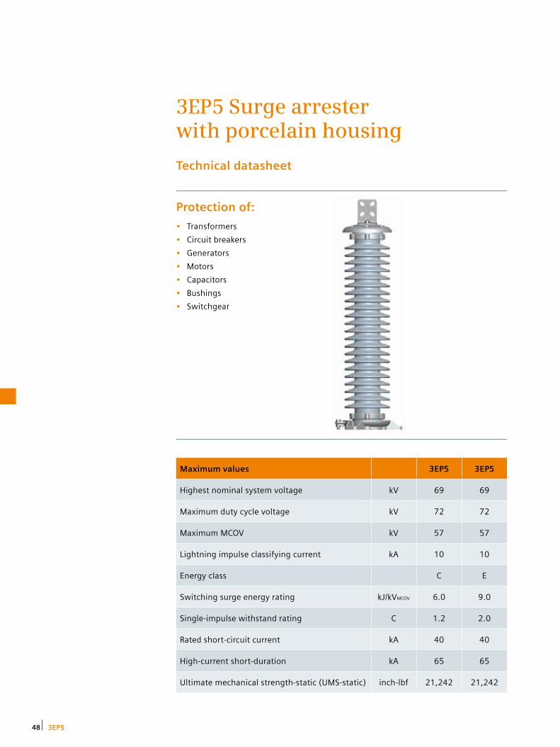
3EP5 Surge arrester with porcelain housing
Technical datasheet
Protection of:
• Transformers
• Circuit breakers
• Generators
• Motors
• Capacitors
• Bushings
• Switchgear
Maximum values 3EP5 3EP5
Highest nominal system voltage kV 69 69
Maximum duty cycle voltage kV 72 72
Maximum MCOV kV 57 57
Lightning impulse classifying current kA 10 10
Energy class C E
Switching surge energy rating kJ/kVMCOV 6.0 9.0
Single-impulse withstand rating C 1.2 2.0
Rated short-circuit current kA 40 40
High-current short-duration kA 65 65
Ultimate mechanical strength-static (UMS-static) inch-lbf 21,242 21,242
48 3EP5
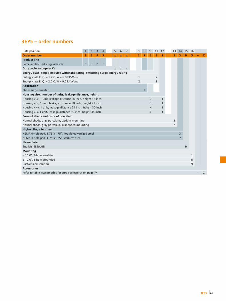
Data position 1 2 3 4 – 5 6 7 – 8 9 10 11 12 – 13 14 15 16
Order number 3 E P 5 x x x 2 P E 3 1 3 X H 5 – Z
Product line
Porcelain-housed surge arrester 3 E P 5
Duty cycle voltage in kV x x x
Energy class, single-impulse withstand rating, switching surge energy rating
Energy class C, Qs = 1.2 C, W = 6.0 kJ/kVMCOV 1 2
Energy class E, Qs = 2.0 C, W = 9.0 kJ/kVMCOV 2 3
Application
Phase surge arrester P
Housing size, number of units, leakage distance, height
Housing »C«, 1 unit, leakage distance 26 inch, height 14 inch C 1
Housing »E«, 1 unit, leakage distance 50 inch, height 22 inch E 1
Housing »H«, 1 unit, leakage distance 74 inch, height 30 inch H 1
Housing »J«, 1 unit, leakage distance 90 inch, height 35 inch J 1
Form of sheds and color of porcelain
Normal sheds, gray porcelain, upright mounting 3
Normal sheds, gray porcelain, suspended mounting 7
High-voltage terminal
NEMA 4-hole pad, 1.75”x1.75”, hot dip galvanized steel X
NEMA 4-hole pad, 1.75”x1.75”, stainless steel Y
Nameplate
English IEEE/ANSI H
Mounting
ø 10.0”, 3-hole insulated 1
ø 10.0”, 3-hole grounded 5
Customized solution 9
Accessories
Refer to table »Accessories for surge arresters« on page 74 – Z
3EP5 – order numbers
493EP5

Ratings and specifications
Electrical characteristics
Duty cycle voltage
MCOV Energy class
Switching surge
energy rating
Single-impulse
withstand rating
Protective level Maximum discharge voltage
Arrester order number
kV
kV
kJ/kVmcov
C
8/20µs 1.5 kA kV cr
8/20µs 3 kA kV cr
8/20µs 5 kA kV cr
8/20µs 10 kA kV cr
8/20µs 20 kA kV cr
8/20µs 40 kA kV cr
45/90µs 500 A kV cr
45/90µs 1 kA kV cr
10 8.4 C 6.0 1.2 22.1 23.1 24.2 26.0 29.1 33.3 20.0 20.8 3EP5 010 - 1PC21 - ….
18 15.3 C 6.0 1.2 39.8 41.7 43.5 46.8 52.4 59.9 36.0 37.4 3EP5 018 - 1PC21 - ….
27 22.0 C 6.0 1.2 59.7 62.5 65.3 70.2 78.6 89.9 54.1 56.2 3EP5 027 - 1PC21 - ….
27 22.0 C 6.0 1.2 59.7 62.5 65.3 70.2 78.6 89.9 54.1 56.2 3EP5 027 - 1PE21 - ….
30 24.4 C 6.0 1.2 66.3 69.4 72.5 78.0 87.4 99.8 60.1 62.4 3EP5 030 - 1PE21 - ….
36 29.0 C 6.0 1.2 79.6 83.3 87.0 93.6 105 120 72.1 74.9 3EP5 036 - 1PE21 - ….
39 31.5 C 6.0 1.2 86.2 90.2 94.3 101 114 130 78.1 81.1 3EP5 039 - 1PE21 - ….
45 36.5 E 9.0 2.0 92.9 97.2 102 108 120 136 86.4 88.6 3EP5 045 - 2PE31 - ….
48 39.0 E 9.0 2.0 99.1 104 108 115 128 145 92.2 94.5 3EP5 048 - 2PE31 - ….
54 42.0 E 9.0 2.0 111 117 122 130 144 163 104 106 3EP5 054 - 2PH31 - ….
60 48.0 E 9.0 2.0 124 130 135 144 160 181 115 118 3EP5 060 - 2PH31 - ….
72 57.0 E 9.0 2.0 149 156 162 173 192 218 138 142 3EP5 072 - 2PH31 - ….
Figure A
Line terminals
NEMA flat terminal
3EP5 …-…..-.X.. (hot dip galvanized)
3EP5 …-…..-.Y.. (stainless steel)
50 3EP5
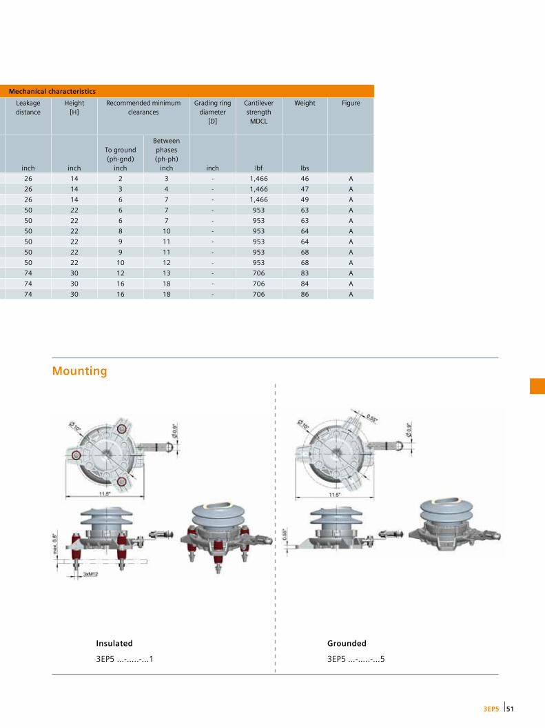
Mechanical characteristics
Leakage distance
Height [H]
Recommended minimum clearances
Grading ring diameter
[D]
Cantilever strength
MDCL
Weight Figure
inch inch
To ground (ph-gnd)
inch
Between phases (ph-ph)
inch inch lbf lbs
26 14 2 3 - 1,466 46 A
26 14 3 4 - 1,466 47 A
26 14 6 7 - 1,466 49 A
50 22 6 7 - 953 63 A
50 22 6 7 - 953 63 A
50 22 8 10 - 953 64 A
50 22 9 11 - 953 64 A
50 22 9 11 - 953 68 A
50 22 10 12 - 953 68 A
74 30 12 13 - 706 83 A
74 30 16 18 - 706 84 A
74 30 16 18 - 706 86 A
Mounting
Insulated
3EP5 …-…..-…1
Grounded
3EP5 …-…..-…5
513EP5

3EP4 Surge arrester with porcelain housing
Technical datasheet
Protection of:
• Transformers
• Circuit breakers
• Generators
• Motors
• Capacitors
• Bushings
• Switchgear
Maximum values 3EP4
Highest nominal system voltage kV 345
Maximum duty cycle voltage kV 276
Maximum MCOV kV 220
Lightning impulse classifying current kA 10
Energy class E
Switching surge energy rating kJ/kVMCOV 9.0
Single-impulse withstand rating C 2.0
Rated short-circuit current kA 65
High-current short-duration kA 65
Ultimate mechanical strength-static (UMS-static) inch-lbf 47,794
52 3EP4
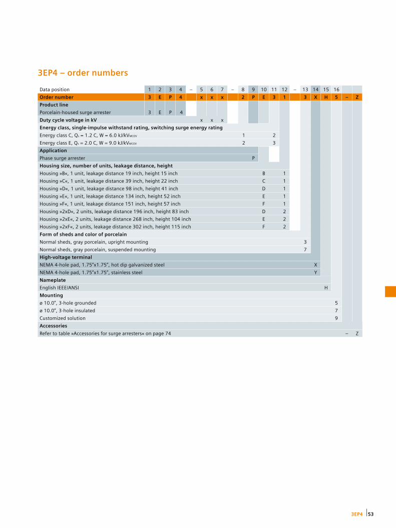
3EP4 – order numbers
Data position 1 2 3 4 – 5 6 7 – 8 9 10 11 12 – 13 14 15 16
Order number 3 E P 4 x x x 2 P E 3 1 3 X H 5 – Z
Product line
Porcelain-housed surge arrester 3 E P 4
Duty cycle voltage in kV x x x
Energy class, single-impulse withstand rating, switching surge energy rating
Energy class C, Qs = 1.2 C, W = 6.0 kJ/kVMCOV 1 2
Energy class E, Qs = 2.0 C, W = 9.0 kJ/kVMCOV 2 3
Application
Phase surge arrester P
Housing size, number of units, leakage distance, height
Housing »B«, 1 unit, leakage distance 19 inch, height 15 inch B 1
Housing »C«, 1 unit, leakage distance 39 inch, height 22 inch C 1
Housing »D«, 1 unit, leakage distance 98 inch, height 41 inch D 1
Housing »E«, 1 unit, leakage distance 134 inch, height 52 inch E 1
Housing »F«, 1 unit, leakage distance 151 inch, height 57 inch F 1
Housing »2xD«, 2 units, leakage distance 196 inch, height 83 inch D 2
Housing »2xE«, 2 units, leakage distance 268 inch, height 104 inch E 2
Housing »2xF«, 2 units, leakage distance 302 inch, height 115 inch F 2
Form of sheds and color of porcelain
Normal sheds, gray porcelain, upright mounting 3
Normal sheds, gray porcelain, suspended mounting 7
High-voltage terminal
NEMA 4-hole pad, 1.75”x1.75”, hot dip galvanized steel X
NEMA 4-hole pad, 1.75”x1.75”, stainless steel Y
Nameplate
English IEEE/ANSI H
Mounting
ø 10.0”, 3-hole grounded 5
ø 10.0”, 3-hole insulated 7
Customized solution 9
Accessories
Refer to table »Accessories for surge arresters« on page 74 – Z
533EP4
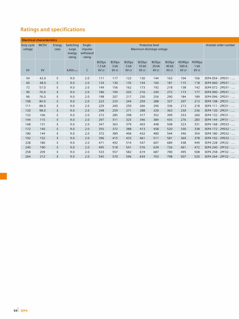
Ratings and specifications
Electrical characteristics
Duty cycle voltage
MCOV Energy class
Switching surge
energy rating
Single-impulse
withstand rating
Protective level Maximum discharge voltage
Arrester order number
kV
kV
kJ/kVmcov
C
8/20µs 1.5 kA kV cr
8/20µs 3 kA kV cr
8/20µs 5 kA kV cr
8/20µs 10 kA kV cr
8/20µs 20 kA kV cr
8/20µs 40 kA kV cr
45/90µs 500 A kV cr
45/90µs 1 kA kV cr
54 42.0 E 9.0 2.0 111 117 122 130 144 163 104 106 3EP4 054 - 2PD31 - ….
60 48.0 E 9.0 2.0 124 130 135 144 160 181 115 118 3EP4 060 - 2PD31 - ….
72 57.0 E 9.0 2.0 149 156 162 173 192 218 138 142 3EP4 072 - 2PD31 - ….
90 70.0 E 9.0 2.0 186 194 203 216 240 272 173 177 3EP4 090 - 2PD31 - ….
96 76.0 E 9.0 2.0 198 207 217 230 256 290 184 189 3EP4 096 - 2PD31 - ….
108 84.0 E 9.0 2.0 223 233 244 259 288 327 207 213 3EP4 108 - 2PE31 - ….
111 88.0 E 9.0 2.0 229 240 250 266 296 336 213 218 3EP4 111 - 2PE31 - ….
120 98.0 E 9.0 2.0 248 259 271 288 320 363 230 236 3EP4 120 - 2PE31 - ….
132 106 E 9.0 2.0 272 285 298 317 352 399 253 260 3EP4 132 - 2PE31 - ….
144 115 E 9.0 2.0 297 311 325 346 384 435 276 283 3EP4 144 - 2PF31 - ….
168 131 E 9.0 2.0 347 363 379 403 448 508 323 331 3EP4 168 - 2PD32 - ….
172 140 E 9.0 2.0 355 372 388 413 458 520 330 338 3EP4 172 - 2PD32 - ….
180 144 E 9.0 2.0 372 389 406 432 480 544 346 354 3EP4 180 - 2PD32 - ….
192 152 E 9.0 2.0 396 415 433 461 511 581 369 378 3EP4 192 - 2PD32 - ….
228 180 E 9.0 2.0 471 492 514 547 607 689 438 449 3EP4 228 - 2PE32 - ….
240 190 E 9.0 2.0 495 518 541 576 639 726 461 472 3EP4 240 - 2PF32 - ….
258 209 E 9.0 2.0 533 557 582 619 687 780 495 508 3EP4 258 - 2PF32 - ….
264 212 E 9.0 2.0 545 570 596 634 703 798 507 520 3EP4 264 - 2PF32 - ….
54 3EP4

Mechanical characteristics
Leakage distance
Height [H]
Recommended minimum clearances
Grading ring diameter
[D]
Cantilever strength
MDCL
Weight Figure
inch inch
To ground (ph-gnd)
inch
Between phases (ph-ph)
inch inch lbf lbs
98 41 12 13 - 1,156 101 A
98 41 16 18 - 1,156 102 A
98 41 16 18 - 1,156 105 A
98 41 21 24 - 1,156 108 A
98 41 31 34 - 1,156 109 A
134 52 31 34 - 923 138 A
134 52 31 34 - 923 138 A
134 52 31 34 - 923 139 A
134 52 50 56 - 923 142 A
151 57 50 56 - 831 155 A
196 83 50 56 - 578 227 B
196 83 50 56 - 578 227 B
196 83 50 56 - 578 228 B
196 83 50 56 - 578 231 B
268 104 59 66 31 462 291 C
302 115 59 66 31 416 320 C
302 115 68 77 31 416 324 C
302 115 68 77 31 416 325 C
553EP4

Figure A Figure B Figure C
56 3EP4

Mounting
Line terminals
NEMA flat terminal
3EP4 …-…..-.X.. (hot dip galvanized)
3EP4 …-…..-.Y.. (stainless steel)
Insulated
3EP4 …-…..-…7
Grounded
3EP4 …-…..-…5
573EP4

3EP6 Surge arrester with porcelain housing
Technical datasheet
Protection of:
• Transformers
• Circuit breakers
• Generators
• Motors
• Capacitors
• Bushings
• Switchgear
Maximum values 3EP6 3EP6 3EP6
Highest nominal system voltage kV 345 500 765
Maximum duty cycle voltage kV 288 444 588
Maximum MCOV kV 230 353 470
Lightning impulse classifying current kA 10 15 20
Energy class E G J
Switching surge energy rating kJ/kVMCOV 9.0 13 18
Single-impulse withstand rating C 2.0 2.8 3.6
Rated short-circuit current kA 65 65 65
High-current short-duration kA 65 65 100
Ultimate mechanical strength-static (UMS-static)
inch-lbf 191,175 191,175 191,175
58 3EP6

Data position 1 2 3 4 – 5 6 7 – 8 9 10 11 12 – 13 14 15 16
Order number 3 E P 6 x x x 2 P F 3 1 4 X H 5 – Z
Product line
Porcelain-housed surge arrester 3 E P 6
Duty cycle voltage in kV x x x
Energy class, single-impulse withstand rating, switching surge energy rating
Energy class E, Qs = 2.0 C, W = 9.0 kJ/kVMCOV 2 3
Energy class G, Qs = 2.8 C, W = 13.0 kJ/kVMCOV 3 4
Energy class J, Qs = 3.6 C, W = 18.0 kJ/kVMCOV 4 5
Application
Phase surge arrester P
Housing size, number of units, leakage distance, height
Housing »C«, 1 unit, leakage distance 155 inch, height 51 inch C 1
Housing »D«, 1 unit, leakage distance 177 inch, height 57 inch D 1
Housing »F«, 1 unit, leakage distance 229 inch, height 69 inch F 1
Housing »G«, 1 unit, leakage distance 249 inch, height 74 inch G 1
Housing »J«, 1 unit, leakage distance 302 inch, height 86 inch J 1
Housing »2xD«, 2 units, leakage distance 355 inch, height 115 inch D 2
Housing »D+F«, 2 units, leakage distance 406 inch, height 127 inch N 2
Housing »D+G«, 2 units, leakage distance 427 inch, height 131 inch P 2
Housing »2xF«, 2 units, leakage distance 457 inch, height 138 inch F 2
Housing »2xG«, 2 units, leakage distance 499 inch, height 147 inch G 2
Housing »F+J«, 2 units, leakage distance 531 inch, height 155 inch R 2
Housing »G+J«, 2 units, leakage distance 551 inch, height 160 inch S 2
Housing »2xJ«, 2 units, leakage distance 604 inch, height 173 inch J 2
Housing »3xF«, 3 units, leakage distance 686 inch, height 207 inch F 3
Housing »3xG«, 3 units, leakage distance 748 inch, height 221 inch G 3
Housing »3xJ«, 3 units, leakage distance 906 inch, height 259 inch J 3
Form of sheds and color of porcelain
Alternating sheds, gray porcelain, upright mounting 4
Alternating sheds, gray porcelain, suspended mounting 8
High-voltage terminal
NEMA 4-hole pad, 1.75”x1.75”, hot dip galvanized steel X
NEMA 4-hole pad, 1.75”x1.75”, stainless steel Y
Nameplate
English IEEE/ANSI H
Mounting
ø 10.0”, 3-hole grounded 5
ø 16.5”, 3-hole grounded 6
ø 10.0”, 3-hole insulated 7
ø 16.5”, 3-hole insulated 8
Customized solution 9
Accessories
Refer to table »Accessories for surge arresters« on page 74 – Z
3EP6 – order numbers
593EP6
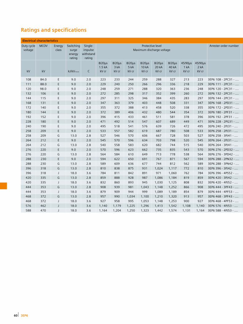
Ratings and specifications
Electrical characteristics
Duty cycle voltage
MCOV Energy class
Switching surge
energy rating
Single-impulse
withstand rating
Protective level Maximum discharge voltage
Arrester order number
kV
kV
kJ/kVmcov
C
8/20µs 1.5 kA kV cr
8/20µs 3 kA kV cr
8/20µs 5 kA kV cr
8/20µs 10 kA kV cr
8/20µs 20 kA kV cr
8/20µs 40 kA kV cr
45/90µs 1 kA kV cr
45/90µs 2 kA kV cr
108 84.0 E 9.0 2.0 223 233 244 259 288 327 213 223 3EP6 108 - 2PC31 - ….
111 88.0 E 9.0 2.0 229 240 250 266 296 336 218 229 3EP6 111 - 2PC31 - ….
120 98.0 E 9.0 2.0 248 259 271 288 320 363 236 248 3EP6 120 - 2PC31 - ….
132 106 E 9.0 2.0 272 285 298 317 352 399 260 272 3EP6 132 - 2PC31 - ….
144 115 E 9.0 2.0 297 311 325 346 384 435 283 297 3EP6 144 - 2PC31 - ….
168 131 E 9.0 2.0 347 363 379 403 448 508 331 347 3EP6 168 - 2PD31 - ….
172 140 E 9.0 2.0 355 372 388 413 458 520 338 355 3EP6 172 - 2PD31 - ….
180 144 E 9.0 2.0 372 389 406 432 480 544 354 372 3EP6 180 - 2PF31 - ….
192 152 E 9.0 2.0 396 415 433 461 511 581 378 396 3EP6 192 - 2PF31 - ….
228 180 E 9.0 2.0 471 492 514 547 607 689 449 471 3EP6 228 - 2PG31 - ….
240 190 E 9.0 2.0 495 518 541 576 639 726 472 495 3EP6 240 - 2PJ31 - ….
258 209 E 9.0 2.0 533 557 582 619 687 780 508 533 3EP6 258 - 2PJ31 - ….
258 209 G 13.0 2.8 527 546 570 606 667 728 503 527 3EP6 258 - 3PJ41 - ….
264 212 E 9.0 2.0 545 570 596 634 703 798 520 545 3EP6 264 - 2PJ31 - ….
264 212 G 13.0 2.8 540 558 583 620 682 744 515 540 3EP6 264 - 3PJ41 - ….
276 220 E 9.0 2.0 570 596 623 662 735 835 543 570 3EP6 276 - 2PD32 - ….
276 220 G 13.0 2.8 564 584 610 649 713 778 538 564 3EP6 276 - 3PD42 - ….
288 230 E 9.0 2.0 594 622 650 691 767 871 567 594 3EP6 288 - 2PN32 - ….
288 230 G 13.0 2.8 589 609 636 677 744 812 562 589 3EP6 288 - 3PN42 - ….
396 318 G 13.0 2.8 810 838 875 931 1,024 1,117 772 810 3EP6 396 - 3PJ42 - ….
396 318 J 18.0 3.6 784 811 842 891 971 1,060 762 784 3EP6 396 - 4PS52 - ….
420 335 G 13.0 2.8 859 888 928 987 1,086 1,184 819 859 3EP6 420 - 3PJ42 - ….
420 335 J 18.0 3.6 832 860 893 945 1,030 1,125 808 832 3EP6 420 - 4PJ52 - ….
444 353 G 13.0 2.8 908 939 981 1,043 1,148 1,252 866 908 3EP6 444 - 3PF43 - ….
444 353 J 18.0 3.6 879 909 944 999 1,089 1,189 854 879 3EP6 444 - 4PF53 - ….
468 372 G 13.0 2.8 957 990 1,034 1,100 1,210 1,320 913 957 3EP6 468 - 3PF43 - ….
468 372 J 18.0 3.6 927 958 995 1,053 1,148 1,253 900 927 3EP6 468 - 4PF53 - ….
576 462 J 18.0 3.6 1,140 1,179 1,225 1,296 1,413 1,542 1,108 1,140 3EP6 576 - 4PJ53 - ….
588 470 J 18.0 3.6 1,164 1,204 1,250 1,323 1,442 1,574 1,131 1,164 3EP6 588 - 4PJ53 - ….
60 3EP6

Mechanical characteristics
Leakage distance
Height [H]
Recommended minimum clearances
Grading ring diameter
[D]
Cantilever strength
MDCL
Weight Figure
inch inch
To ground (ph-gnd)
inch
Between phases (ph-ph)
inch inch lbf lbs
155 51 31 34 - 3,738 338 A
155 51 31 34 - 3,738 338 A
155 51 31 34 - 3,738 339 A
155 51 50 56 - 3,738 341 A
155 51 50 56 - 3,738 344 A
177 57 50 56 - 3,328 378 A
177 57 50 56 - 3,328 378 A
229 69 50 56 - 2,776 440 A
229 69 50 56 - 2,776 442 A
249 74 59 66 - 2,598 475 A
302 86 59 66 - 2,218 542 A
302 86 68 77 31 2,218 553 B
302 86 68 77 31 2,218 593 B
302 86 68 77 31 2,218 554 B
302 86 68 77 31 2,218 595 B
355 115 68 77 31 1,661 698 C
355 115 68 77 31 1,661 741 C
406 127 76 85 39 1,511 766 C
406 127 68 77 39 1,511 810 C
604 173 97 111 47 1,108 1,093 C
551 160 97 111 47 1,195 1,058 C
604 173 109 125 47 1,108 1,101 C
604 173 97 111 47 1,108 1,133 C
686 207 109 125 59 923 974 D
686 207 109 125 59 923 1,006 D
686 207 109 125 59 923 983 D
686 207 109 125 59 923 1,017 D
906 259 109 125 83 738 1,322 D
906 259 109 125 83 738 1,322 D
613EP6
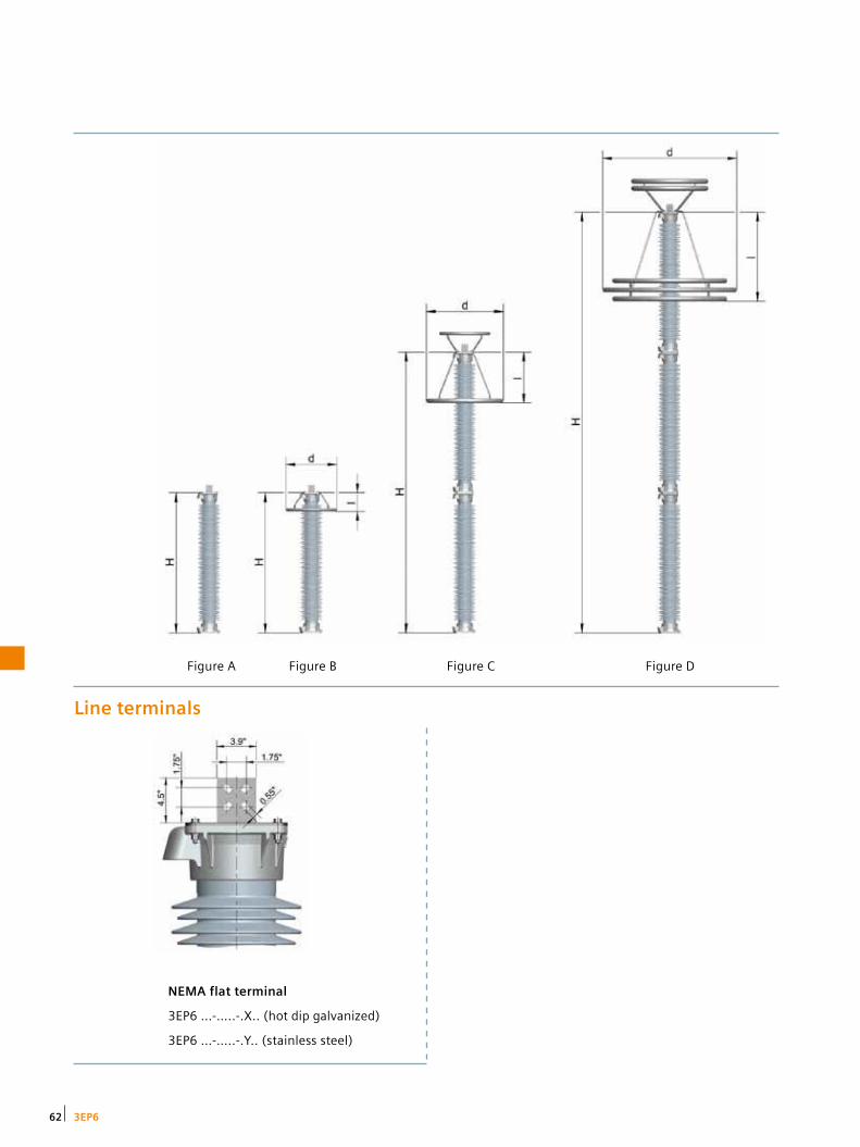
Figure DFigure CFigure BFigure A
Line terminals
NEMA flat terminal
3EP6 …-…..-.X.. (hot dip galvanized)
3EP6 …-…..-.Y.. (stainless steel)
62 3EP6

Mounting
Insulated
3EP6 …-…..-…7
Grounded
3EP6 …-…..-…5
Grounded
3EP6 …-…..-…6
Insulated
3EP6 …-…..-…8
633EP6

3EQ1 Surge arrester with composite hollow core design
Technical datasheet
Protection of:
• Transformers
• Circuit breakers
• Generators
• Motors
• Capacitors
• Bushings
• Switchgear
Maximum values 3EQ1 3EQ1
Highest nominal system voltage kV 115 230
Maximum duty cycle voltage kV 96 192
Maximum MCOV kV 76.8 152
Lightning impulse classifying current kA 10 10
Energy class C E
Switching surge energy rating kJ/kVMCOV 6.0 9.0
Single-impulse withstand rating C 1.2 2.0
Rated short-circuit current kA 40 40
High-current short-duration kA 65 65
Maximum design cantilever load (MDCL) inch-lbf 37,173 37,173
64 3EQ1

Data position 1 2 3 4 – 5 6 7 – 8 9 10 11 12 – 13 14 15 16
Order number 3 E Q 1 x x x 2 P J 3 1 4 X H 5 – Z
Product line
Silicone rubber-housed surge arrester, hollow core design
3 E Q 1
Duty cycle voltage in kV x x x
Energy class, single-impulse withstand rating, switching surge energy rating
Energy class C, Qs = 1.2 C, W = 6.0 kJ/kVMCOV 1 2
Energy class E, Qs = 2.0 C, W = 9.0 kJ/kVMCOV 2 3
Application
Phase surge arrester P
Housing size, number of units, leakage distance, height
Housing »B«, 1 unit, leakage distance 82 inch, height 35 inch B 1
Housing »E«, 1 unit, leakage distance 104 inch, height 41 inch E 1
Housing »J«, 1 unit, leakage distance 133 inch, height 49 inch J 1
Housing »P«, 1 unit, leakage distance 170 inch, height 58 inch P 1
Housing »S«, 1 unit, leakage distance 193 inch, height 64 inch S 1
Housing »2xJ«, 2 units, leakage distance 267 inch, height 97 inch J 2
Housing »2xP«, 2 units, leakage distance 341 inch, height 117 inch P 2
Form of sheds and color of silicone rubber
Alternating sheds, gray silicone rubber, upright mounting 4
Alternating sheds, gray silicone rubber, suspended mounting 8
High-voltage terminal
NEMA 4-hole pad, 1.75”x1.75”, hot dip galvanized steel X
NEMA 4-hole pad, 1.75”x1.75”, stainless steel Y
Nameplate
English IEEE/ANSI H
Mounting
ø 10.0”, 3-hole grounded 5
ø 10.0”, 3-hole insulated 7
Customized solution 9
Accessories
Refer to table »Accessories for surge arresters« on page 74 – Z
3EQ1 – order numbers
653EQ1

Ratings and specifications
Electrical characteristics
Duty cycle voltage
MCOV Energy class
Switching surge
energy rating
Single-impulse
withstand rating
Protective level Maximum discharge voltage
Arrester order number
kV
kV
kJ/kVmcov
C
8/20µs 1.5 kA kV cr
8/20µs 3 kA kV cr
8/20µs 5 kA kV cr
8/20µs 10 kA kV cr
8/20µs 20 kA kV cr
8/20µs 40 kA kV cr
45/90µs 500 A kV cr
45/90µs 1 kA kV cr
30 24.4 C 6.0 1.2 66.3 69.4 72.5 78.0 87.4 99.8 60.1 62.4 3EQ1 030 - 1PB21 - ….
30 24.4 E 9.0 2.0 61.9 64.8 67.7 72.0 79.9 90.7 57.6 59.0 3EQ1 030 - 2PB31 - ….
36 29.0 C 6.0 1.2 79.6 83.3 87.0 93.6 105 120 72.1 74.9 3EQ1 036 - 1PB21 - ….
39 31.5 C 6.0 1.2 86.2 90.2 94.3 101 114 130 78.1 81.1 3EQ1 039 - 1PB21 - ….
45 36.5 E 9.0 2.0 92.9 97.2 102 108 120 136 86.4 88.6 3EQ1 045 - 2PB31 - ….
48 39.0 E 9.0 2.0 99.1 104 108 115 128 145 92.2 94.5 3EQ1 048 - 2PB31 - ….
54 42.0 E 9.0 2.0 111 117 122 130 144 163 104 106 3EQ1 054 - 2PB31 - ….
60 48.0 E 9.0 2.0 124 130 135 144 160 181 115 118 3EQ1 060 - 2PB31 - ….
72 57.0 E 9.0 2.0 149 156 162 173 192 218 138 142 3EQ1 072 - 2PB31 - ….
90 70.0 E 9.0 2.0 186 194 203 216 240 272 173 177 3EQ1 090 - 2PE31 - ….
96 76.0 E 9.0 2.0 198 207 217 230 256 290 184 189 3EQ1 096 - 2PE31 - ….
108 84.0 E 9.0 2.0 223 233 244 259 288 327 207 213 3EQ1 108 - 2PJ31 - ….
111 88.0 E 9.0 2.0 229 240 250 266 296 336 213 218 3EQ1 111 - 2PJ31 - ….
120 98.0 E 9.0 2.0 248 259 271 288 320 363 230 236 3EQ1 120 - 2PJ31 - ….
132 106 E 9.0 2.0 272 285 298 317 352 399 253 260 3EQ1 132 - 2PJ31 - ….
144 115 E 9.0 2.0 297 311 325 346 384 435 276 283 3EQ1 144 - 2PP31 - ….
168 131 E 9.0 2.0 347 363 379 403 448 508 323 331 3EQ1 168 - 2PP31 - ….
172 140 E 9.0 2.0 355 372 388 413 458 520 330 338 3EQ1 172 - 2PS31 - ….
180 144 E 9.0 2.0 372 389 406 432 480 544 346 354 3EQ1 180 - 2PS31 - ….
192 152 E 9.0 2.0 396 415 433 461 511 581 369 378 3EQ1 192 - 2PS31 - ….
Figure A
Line terminals
NEMA flat terminal
3EQ1 …-…..-.X.. (hot dip galvanized)
3EQ1 …-…..-.Y.. (stainless steel)
66 3EQ1

Mechanical characteristics
Leakage distance
Height [H]
Recommended minimum clearances
Grading ring diameter
[D]
Cantilever strength
MDCL
Weight Figure
inch inch
To ground (ph-gnd)
inch
Between phases (ph-ph)
inch inch lbf lbs
82 35 6 7 - 1,067 53 A
82 35 6 7 - 1,067 54 A
82 35 8 10 - 1,067 54 A
82 35 9 11 - 1,067 54 A
82 35 9 11 - 1,067 58 A
82 35 10 12 - 1,067 58 A
82 35 12 13 - 1,067 59 A
82 35 16 18 - 1,067 60 A
82 35 16 18 - 1,067 61 A
104 41 21 24 - 912 70 A
104 41 31 34 - 912 71 A
133 49 31 34 - 765 78 A
133 49 31 34 - 765 78 A
133 49 31 34 - 765 79 A
133 49 50 56 - 765 82 A
170 58 50 56 - 636 87 A
170 58 50 56 - 636 94 A
193 64 50 56 - 577 98 A
193 64 50 56 - 577 99 A
193 64 50 56 - 577 102 A
Insulated
3EQ1 …-…..-…7
Mounting
Grounded
3EQ1 …-…..-…5
673EQ1

3EQ4 Surge arrester with composite hollow core design
Technical datasheet
Protection of:
• Transformers
• Circuit breakers
• Generators
• Motors
• Capacitors
• Bushings
• Switchgear
Maximum values 3EQ4 3EQ4 3EQ4 3EQ4
Highest nominal system voltage kV 345 500 765 765
Maximum duty cycle voltage kV 288 444 588 588
Maximum MCOV kV 230 353 470 470
Lightning impulse classifying current kA 10 15 20 20
Energy class E G J K
Switching surge energy rating kJ/kVMCOV 9.0 13 18 21
Single-impulse withstand rating C 2.0 2.8 3.6 6.0
Rated short-circuit current kA 651) 651) 651) 65
High-current short-duration kA 65 65 100 100
Maximum design cantilever load (MDCL)
inch-lbf130,106 / 235,430
130,106 / 235,430
130,106 / 235,430
130,106 / 235,430
1) Increased rated short-circuit current of 80 kA available on request
68 3EQ4

Data position 1 2 3 4 – 5 6 7 – 8 9 10 11 12 – 13 14 15 16
Order number 3 E Q 4 x x x 4 P V 5 2 4 X H 5 – Z
Product line
Silicone rubber-housed surge arrester, hollow core design
3 E Q 4
Duty cycle voltage in kV x x x
Energy class, single-impulse withstand rating, switching surge energy rating
Energy class E, Qs = 2.0 C, W = 9.0 kJ/kVMCOV 2 3
Energy class G, Qs = 2.8 C, W = 13.0 kJ/kVMCOV 3 4
Energy class J, Qs = 3.6 C, W = 18.0 kJ/kVMCOV 4 5
Energy class K, Qs = 6.0 C, W = 21.0 kJ/kVMCOV 5 5
Application
Phase surge arrester P
Housing size, number of units, leakage distance, height
Housing »D«, 1 unit, leakage distance 67 inch, height 34 inch D 1
Housing »E«, 1 unit, leakage distance 82 inch, height 38 inch E 1
Housing »H«, 1 unit, leakage distance 126 inch, height 50 inch H 1
Housing »J«, 1 unit, leakage distance 139 inch, height 54 inch J 1
Housing »K«, 1 unit, leakage distance 156 inch, height 57 inch K 1
Housing »N«, 1 unit, leakage distance 200 inch, height 69 inch N 1
Housing »P«, 1 unit, leakage distance 215 inch, height 73 inch P 1
Housing »R«, 1 unit, leakage distance 244 inch, height 81 inch R 1
Housing »R«, 1 unit, leakage distance 244 inch, height 81 inch, increased MDCL R 5
Housing »S«, 1 unit, leakage distance 259 inch, height 85 inch S 1
Housing »S«, 1 unit, leakage distance 259 inch, height 85 inch, increased MDCL S 5
Housing »V«, 1 unit, leakage distance 304 inch, height 97 inch V 1
Housing »V«, 1 unit, leakage distance 304 inch, height 97 inch, increased MDCL V 5
Housing »2xN«, 2 units, leakage distance 400 inch, height 139 inch N 2
Housing »2xN«, 2 units, leakage distance 400 inch, height 139 inch, increased MDCL N 6
Housing »2xP«, 2 units, leakage distance 430 inch, height 146 inch P 2
Housing »2xP«, 2 units, leakage distance 430 inch, height 146 inch, increased MDCL P 6
Housing »2xR«, 2 units, leakage distance 489 inch, height 162 inch R 2
Housing »2xS«, 2 units, leakage distance 519 inch, height 170 inch S 2
Housing »2xS«, 2 units, leakage distance 519 inch, height 170 inch, increased MDCL S 6
Housing »2xV«, 2 units, leakage distance 607 inch, height 194 inch V 2
Housing »2xV«, 2 units, leakage distance 607 inch, height 194 inch, increased MDCL V 6
Housing »3xP«, 3 units, leakage distance 645 inch, height 220 inch, increased MDCL P 7
Housing »3xS«, 3 units, leakage distance 778 inch, height 255 inch, increased MDCL S 7
Form of sheds and color of silicone rubber
Alternating sheds, gray silicone rubber, upright mounting 4
Alternating sheds, gray silicone rubber, suspended mounting 8
High-voltage terminal
NEMA 4-hole pad, 1.75”x1.75”, hot dip galvanized steel X
NEMA 4-hole pad, 1.75”x1.75”, stainless steel Y
Nameplate
English IEEE/ANSI H
Mounting
ø 10.0”, 3-hole grounded (only with 12th position = 1, 2, 3) 5
ø 16.5”, 3-hole grounded (only with 12th position = 1, 2, 3) 6
ø 10.0”, 3-hole insulated (only with 12th position = 1, 2, 3) 7
ø 16.5”, 3-hole insulated (only with 12th position = 1, 2, 3) 8
ø 10.0”, 3-hole grounded, increased MDCL (only with 12th position = 5, 6, 7) 9 R4D
ø 16.5”, 3-hole grounded, increased MDCL (only with 12th position = 5, 6, 7) 9 R4E
ø 10.0”, 3-hole insulated, increased MDCL (only with 12th position = 5, 6, 7) 9 R4F
Accessories
Refer to table »Accessories for surge arresters« on page 74 – Z
3EQ4 – order numbers
693EQ4

Ratings and specifications
Electrical characteristics
Duty cycle voltage
MCOV Energy class
Switching surge
energy rating
Single-impulse
withstand rating
Protective level Maximum discharge voltage
Arrester order number
kV
kV
kJ/kVmcov
C
8/20µs 1.5 kA kV cr
8/20µs 3 kA kV cr
8/20µs 5 kA kV cr
8/20µs 10 kA kV cr
8/20µs 20 kA kV cr
8/20µs 40 kA kV cr
45/90µs 1 kA kV cr
45/90µs 2 kA kV cr
45 36.5 E 9.0 2.0 92.9 97.2 102 108 120 136 88.6 92.9 3EQ4 045 - 2PD31 - ….
60 48.0 E 9.0 2.0 124 130 135 144 160 181 118 124 3EQ4 060 - 2PE31 - ….
90 70.0 E 9.0 2.0 186 194 203 216 240 272 177 186 3EQ4 090 - 2PH31 - ….
96 76.0 E 9.0 2.0 198 207 217 230 256 290 189 198 3EQ4 096 - 2PJ31 - ….
108 84.0 E 9.0 2.0 223 233 244 259 288 327 213 223 3EQ4 108 - 2PK31 - ….
180 144 E 9.0 2.0 372 389 406 432 480 544 354 372 3EQ4 180 - 2PN31 - ….
180 144 E 9.0 2.0 372 389 406 432 480 544 354 372 3EQ4 180 - 2PV31 - ….
180 144 G 13.0 2.8 368 381 398 423 465 508 351 368 3EQ4 180 - 3PR41 - ….
228 180 E 9.0 2.0 471 492 514 547 607 689 449 471 3EQ4 228 - 2PV31 - ….
258 209 E 9.0 2.0 533 557 582 619 687 780 508 533 3EQ4 258 - 2PV31 - ….
258 209 G 13.0 2.8 527 546 570 606 667 728 503 527 3EQ4 258 - 3PV41 - ….
258 209 J 18.0 3.6 511 528 549 581 633 691 496 511 3EQ4 258 - 4PM52 - ….
276 220 E 9.0 2.0 570 596 623 662 735 835 543 570 3EQ4 276 - 2PV31 - ….
276 220 E 9.0 2.0 570 596 623 662 735 835 543 570 3EQ4 276 - 2PN32 - ….
276 220 G 13.0 2.8 564 584 610 649 713 778 538 564 3EQ4 276 - 3PN42 - ….
276 220 J 18.0 3.6 546 565 587 621 677 739 531 546 3EQ4 276 - 4PR52 - ….
288 230 E 9.0 2.0 594 622 650 691 767 871 567 594 3EQ4 288 - 2PN32 - ….
288 230 G 13.0 2.8 589 609 636 677 744 812 562 589 3EQ4 288 - 3PN42 - ….
288 230 J 18.0 3.6 570 590 612 648 706 771 554 570 3EQ4 288 - 4PV51 - ….
396 318 J 18.0 3.6 784 811 842 891 971 1,060 762 784 3EQ4 396 - 4PV52 - ….
396 318 J 18.0 3.6 784 811 842 891 971 1,060 762 784 3EQ4 396 - 4PV56 - ….
420 335 J 18.0 3.6 832 860 893 945 1,030 1,125 808 832 3EQ4 420 - 4PV52 - ….
420 335 J 18.0 3.6 832 860 893 945 1,030 1,125 808 832 3EQ4 420 - 4PV56 - ….
444 353 J 18.0 3.6 879 909 944 999 1,089 1,189 854 879 3EQ4 444 - 4PV52 - ….
444 353 J 18.0 3.6 879 909 944 999 1,089 1,189 854 879 3EQ4 444 - 4PV56 - ….
588 470 J 18.0 3.6 1,164 1,204 1,250 1,323 1,442 1,574 1,131 1,164 3EQ4 588 - 4PS57 - ….
70 3EQ4

Mechanical characteristics
Leakage distance
Height [H]
Recommended minimum clearances
Grading ring diameter
[D]
Cantilever strength
MDCL
Weight Figure
inch inch
To ground (ph-gnd)
inch
Between phases (ph-ph)
inch inch lbf lbs
67 34 9 11 - 3,843 203 A
82 38 16 18 - 3,442 208 A
126 50 21 24 - 2,623 220 A
139 54 31 34 - 2,430 224 A
156 57 31 34 - 2,263 229 A
200 69 50 56 - 1,878 251 A
304 97 50 56 - 1,343 279 A
244 81 50 56 - 1,604 287 A
304 97 59 66 - 1,343 290 A
304 97 68 77 - 1,343 297 A
304 97 68 77 - 1,343 319 A
371 131 59 66 39 995 472 B
304 97 68 77 - 1,343 302 A
400 139 68 77 39 939 441 B
400 139 68 77 39 939 466 B
489 162 68 77 47 802 506 B
400 139 76 85 39 939 443 B
400 139 68 77 39 939 469 B
304 97 68 77 - 1,343 346 A
607 194 97 111 59 672 580 B
607 194 97 111 59 1,215 580 B
607 194 97 111 59 672 588 B
607 194 97 111 59 1,215 588 B
607 194 109 125 59 672 596 B
607 194 109 125 59 1,215 596 B
778 255 109 125 83 923 785 C
713EQ4
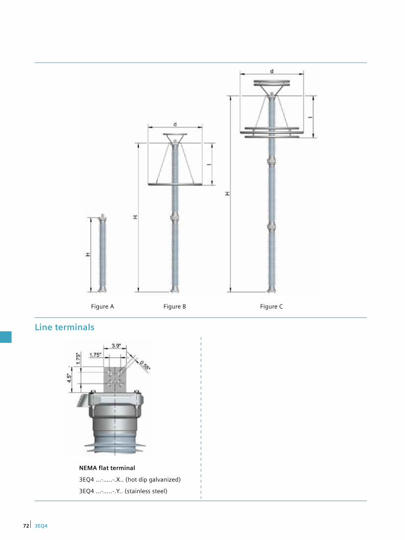
Line terminals
NEMA flat terminal
3EQ4 …-…..-.X.. (hot dip galvanized)
3EQ4 …-…..-.Y.. (stainless steel)
Figure A Figure B Figure C
72 3EQ4
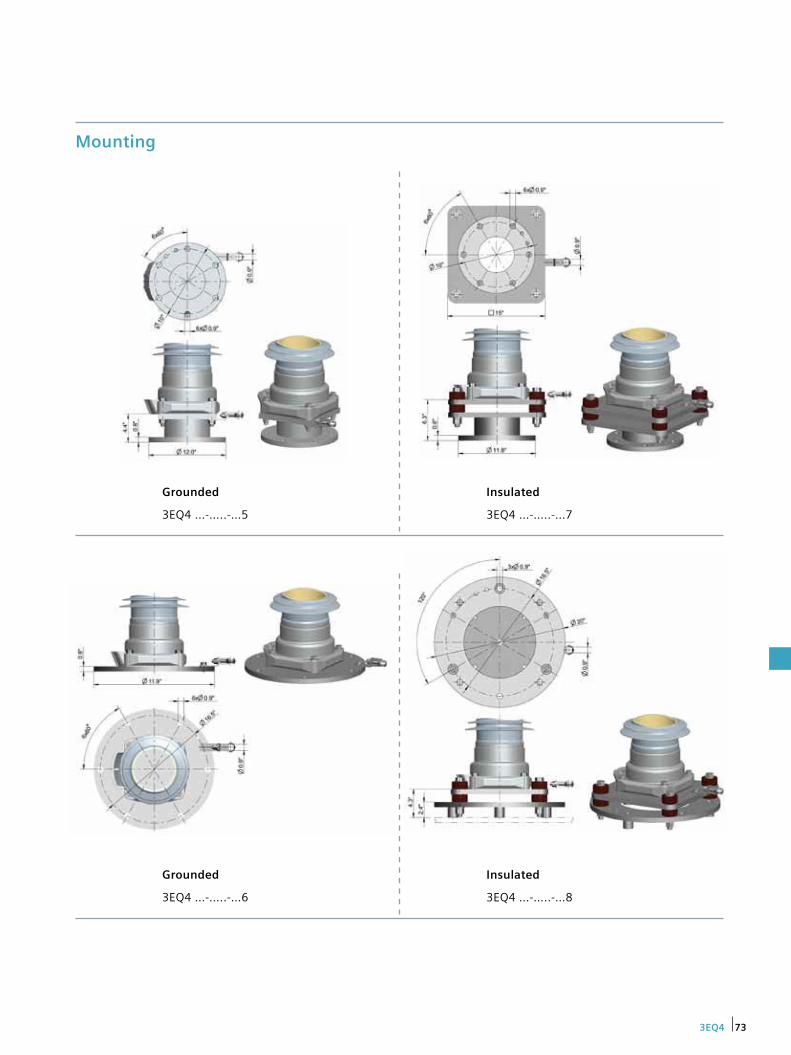
Insulated
3EQ4 …-…..-…8
Mounting
Grounded
3EQ4 …-…..-…5
Insulated
3EQ4 …-…..-…7
Grounded
3EQ4 …-…..-…6
733EQ4

Accessories for surge arresters
Monitoring devices for surge arresters
Siemens surge arresters can optionally be equipped with one or more accessories, listed in the table below. The selected code for the accessory should be added to the order number of the surge arrester. Example: 3EL2 096-2PJ31-4XH5-Z D91 D92.
Surge arresters are highly reliable components in power transmission and distribution systems. When operated in accordance with their specifications, their service life can span as much as 30 years without any maintenance. Nevertheless, overloads may sometimes occur that can cause arrester failure and even endanger the safety of the network.
Monitors assist in the early detection of relevant changes and support security of supply on a whole new level.
Siemens offers a complete line of monitoring devices with a variety of innovative functionalities that can be perfectly matched to the customer’s requirements, ensuring that impending faults will be detected as early as possible and before the security of supply is compromised.
Based on solid experience
Siemens has over 90 years of experience with surge arresters – a solid foundation on which to build a compre-hensive range of monitors that are precisely tailored to today’s surge arrester technology. Siemens’ line of surge arrester monitors ranges from simple counters and condi-tion indicators to periodic analytic condition monitoring and a future live condition monitoring system. All moni-tors provide the requisite information on surge arrester responses and the arrester’s condition – perfectly matched to the respective voltage level, network situation, and customer requirements.
Accessories Code 3EL5 3EL1 3EL2 3EL3 3EP5 3EP4 3EP6 3EQ1 3EQ4
Earth terminal, copper tin-plated D51
DIN/NEMA earth terminal D71
Adapter DIN/NEMA to double DIN flat terminal, including 2 line clamps
D81
Adapter DIN/NEMA to double NEMA flat terminal, including 2 line clamps
D82
Line clamp D91
Eyebolt earth terminal D92
NEMA earth terminal, stainless steel D93
NEMA earth terminal, copper D94
Palm earth terminal, aluminum D95
Earth terminal, 2x D14, stainless steel D96
N2 filling K02
Yellow cover panels for gas diverter K14
Increased rated short-circuit current of 80 kA K80
Optional accessories
74

Surge counter Surge counter with leakage current meter
Surge counter Order number: 3EX5 030-0
Surge counter with auxiliary contact Order number: 3EX5 030-1
Surge counter with leakage current meter (0–30 mA) Order number: 3EX5 050-0
Surge counter with leakage current meter (0–30 mA) with auxiliary contact Order number: 3EX5 050-1
Surge counter with leakage current meter (0–50 mA) Order number: 3EX5 050-2
ACM basic ACM advanced
Arrester Condition Monitor (ACM) basic Order number: 3EX5 080-0
Arrester Condition Monitor (ACM) advanced Order number: 3EX5 080-1 Order number: 3EX5 086 (USB wireless module)
Upgrade from ACM basic to ACM advanced Order number: 3EX5 081
Sensor Display
Sensor Order number: 3EX5 060-1
Display Order number: 3EX5 062-1
Connecting lead (required for operation) Length 3 m. Order number: 3EX5 963-0D Length 6 m. Order number: 3EX5 963-0G Length 10 m. Order number: 3EX5 963-1A Length 12 m. Order number: 3EX5 963-1C Length 14 m. Order number: 3EX5 963-1E Length 16 m. Order number: 3EX5 963-1G Length 18 m. Order number: 3EX5 963-1J Length 20 m. Order number: 3EX5 963-2A Length 22 m. Order number: 3EX5 963-2C Length 24 m. Order number: 3EX5 963-2E Length 26 m. Order number: 3EX5 963-2G Length 28 m. Order number: 3EX5 963-2J Length 30 m. Order number: 3EX5 963-3A
Mounting bracket for surge counter Order number: 3EX5 930
Connection cable for monitors Order number: 3EX5 952
Earth lead Order number: 3EX5 955
Monitoring devices Please refer to our monitoring brochure for more information.
< 200m
75

Published by Siemens AG 2015
Energy Management Freyeslebenstrasse 1 91058 Erlangen, Germany
Please contact us at: Phone: +49 30 386 33 222 Fax: +49 30 386 26 721 E-mail: [email protected]
Article No. E50001-F630-A254-X-4A00 Printed in Germany fb 6514 WÜ WS 01151.0
Subject to change without prior notice. The information in this document contains general descriptions of the technical options available, which may not apply in all cases. The required technical options should therefore be specified in the contract.