Embed Size (px)
Citation preview
1
Engineering Mechanics: ME101
Statics: Lecture 11
5rd Feb 2016
Dr. Poonam Kumari
Department of Mechanical EngineeringIndian Institute of Technology Guwahati
D Block : Room No 201 : Tel: 3434
2
Friction
Types of Friction
Wedges
Journal bearing, thrust bearings
Screws
Flexible belts
Rolling Resistance
Applications of Friction in Machines

3
In this course so far, it has been assumed that all bodies considered have smooth surfaces. Till date, only forces perpendicular to the contact plane can be transferred between two bodies in contact.
This is a proper description of the mechanical behavior if the tangential forces occurring in reality due to the roughness of the surfaces can be neglected.
We will address problems for which this simplification is not valid.
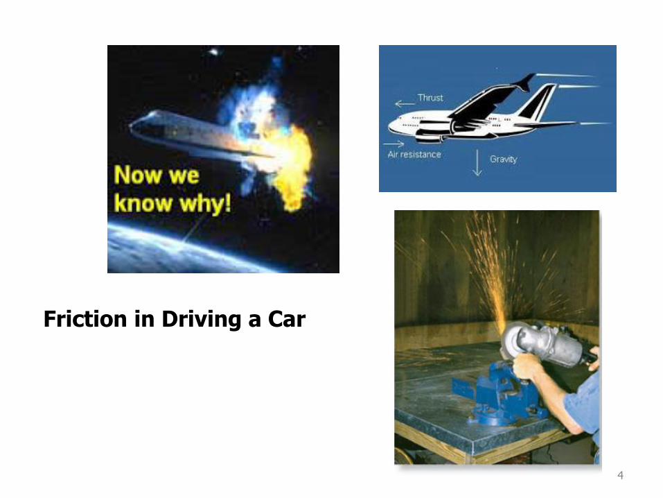
4
Friction in Driving a Car
5
• However, the friction forces are limited in magnitude and will
not prevent motion if sufficiently large forces are applied.
• The distinction between frictionless and rough is, therefore, a
matter of degree.
• There are two types of friction: dry or Coulomb friction and fluid
friction. Fluid friction applies to lubricated mechanisms. The
present discussion is limited to dry friction between
nonlubricated surfaces.
Types of Friction
6
Friction is the force resisting the relative motion of solid surfaces, fluid layers, and material elements sliding against each other.[1] There are several types of friction:
•Dry friction resists relative lateral motion of two solid surfaces in contact. Dry friction is subdivided into static friction ("stiction") between non-moving surfaces, and kinetic friction between moving surfaces.
•Fluid friction describes the friction between layers of a viscous fluid that are moving relative to each other.
•Lubricated friction is a case of fluid friction where a lubricant fluid separates two solid surfaces.
•Skin friction is a component of drag, the force resisting the motion of a fluid across the surface of a body.
•Internal friction is the force resisting motion between the elements making up a solid material while it undergoes deformation.
7
When the surfaces are conjoined, Coulomb friction becomes a very poor approximation (for example, adhesive tape resists sliding even when there is no normal force, or a negative normal force).
In this case, the frictional force may depend strongly on the area of contact. Some drag racing tires are adhesive for this reason.
However, despite the complexity of the fundamental physics behind friction, the relationships are accurate enough to be useful in many applications.
Limitation of Coulomb FrictionFrictional force is proportional to the applied normal force, independently of the contact area
8 - 8
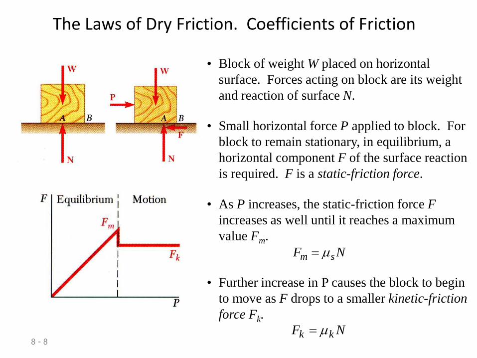
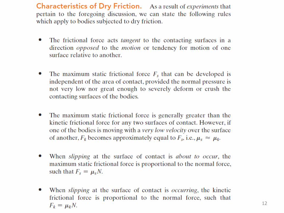
The Laws of Dry Friction. Coefficients of Friction
• Block of weight W placed on horizontal
surface. Forces acting on block are its weight
and reaction of surface N.
• Small horizontal force P applied to block. For
block to remain stationary, in equilibrium, a
horizontal component F of the surface reaction
is required. F is a static-friction force.
• As P increases, the static-friction force F
increases as well until it reaches a maximum
value Fm.
NF sm
• Further increase in P causes the block to begin
to move as F drops to a smaller kinetic-friction
force Fk.
NF kk
8 - 9
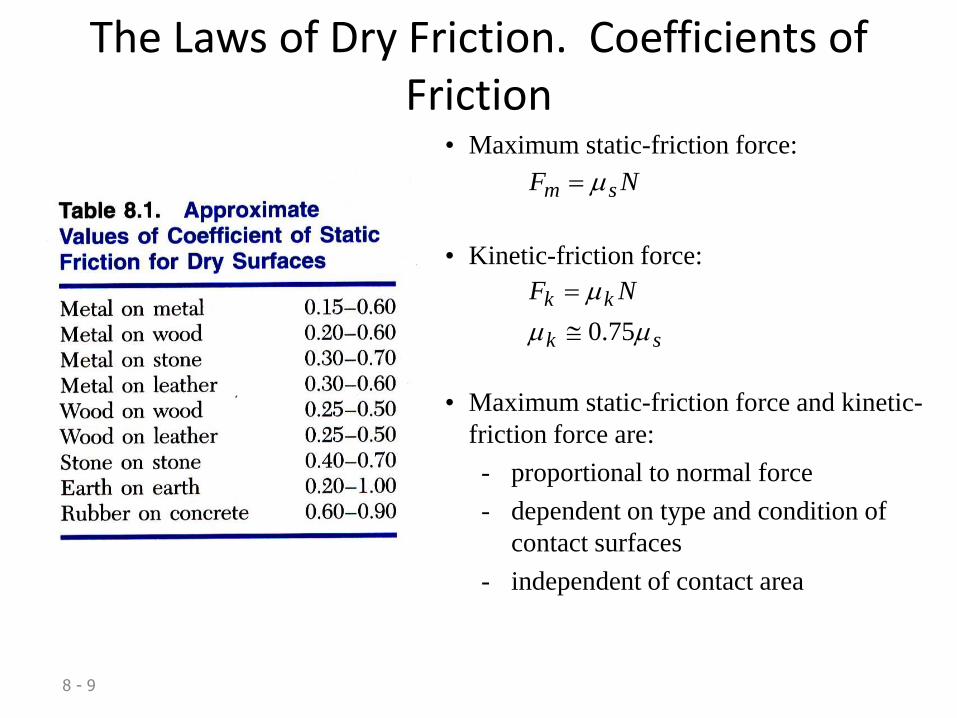
The Laws of Dry Friction. Coefficients of Friction
• Maximum static-friction force:
NF sm
• Kinetic-friction force:
sk
kk NF
75.0
• Maximum static-friction force and kinetic-
friction force are:
- proportional to normal force
- dependent on type and condition of
contact surfaces
- independent of contact area
8 - 10
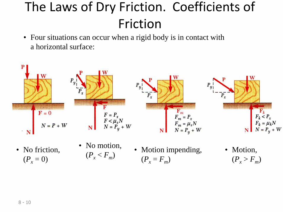
The Laws of Dry Friction. Coefficients of Friction
• Four situations can occur when a rigid body is in contact with
a horizontal surface:
• No friction,
(Px = 0)
• No motion,
(Px < Fm)• Motion impending,
(Px = Fm)
• Motion,
(Px > Fm)
8 - 11
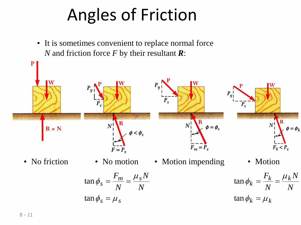
Angles of Friction
• It is sometimes convenient to replace normal force
N and friction force F by their resultant R:
• No friction • Motion impending• No motion
ss
sms
N
N
N
F
tan
tan
• Motion
kk
kkk
N
N
N
F
tan
tan
12
8 - 13
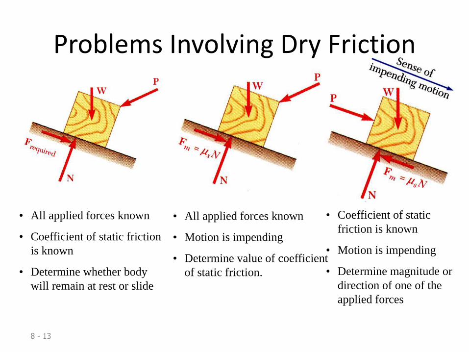
Problems Involving Dry Friction
• All applied forces known
• Coefficient of static friction
is known
• Determine whether body
will remain at rest or slide
• All applied forces known
• Motion is impending
• Determine value of coefficient
of static friction.
• Coefficient of static
friction is known
• Motion is impending
• Determine magnitude or
direction of one of the
applied forces
8 - 14
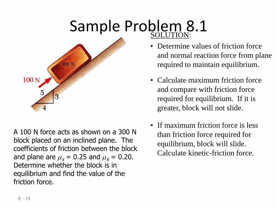
Sample Problem 8.1
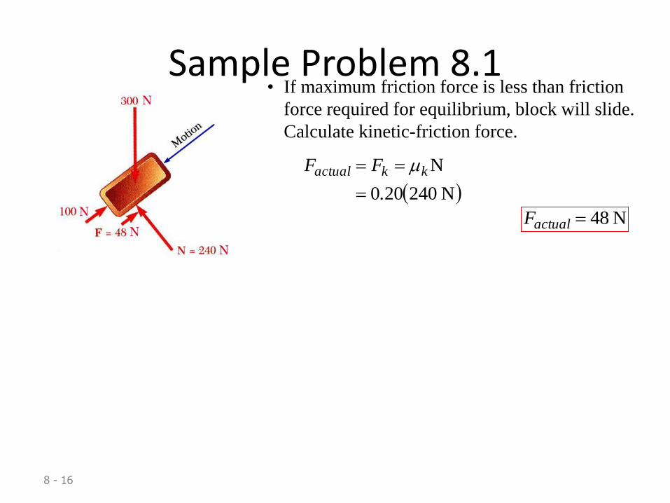
A 100 N force acts as shown on a 300 N block placed on an inclined plane. The coefficients of friction between the block and plane are s = 0.25 and k = 0.20. Determine whether the block is in equilibrium and find the value of the friction force.
SOLUTION:
• Determine values of friction force
and normal reaction force from plane
required to maintain equilibrium.
• Calculate maximum friction force
and compare with friction force
required for equilibrium. If it is
greater, block will not slide.
• If maximum friction force is less
than friction force required for
equilibrium, block will slide.
Calculate kinetic-friction force.
8 - 15
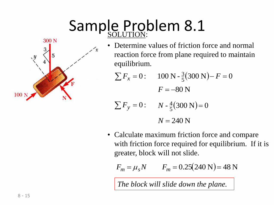
Sample Problem 8.1SOLUTION:
• Determine values of friction force and normal
reaction force from plane required to maintain
equilibrium.
:0 xF 0N 300 - N 10053 F
N 80F
:0 yF 0N 300 - 54 N
N 240N
• Calculate maximum friction force and compare
with friction force required for equilibrium. If it is
greater, block will not slide.
N 48N 24025.0 msm FNF
The block will slide down the plane.
8 - 16
Sample Problem 8.1• If maximum friction force is less than friction
force required for equilibrium, block will slide.
Calculate kinetic-friction force.
N 240200
N
.
FF kkactual
N 48actualF
17
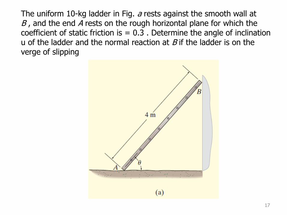
The uniform 10-kg ladder in Fig. a rests against the smooth wall atB , and the end A rests on the rough horizontal plane for which thecoefficient of static friction is = 0.3 . Determine the angle of inclination u of the ladder and the normal reaction at B if the ladder is on the verge of slipping

18
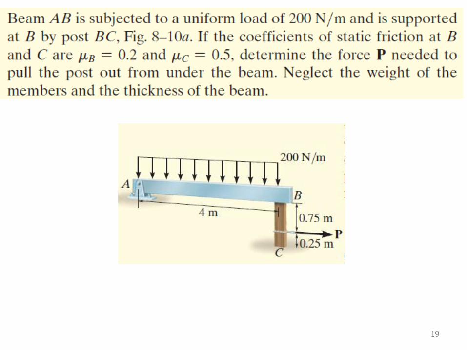
19
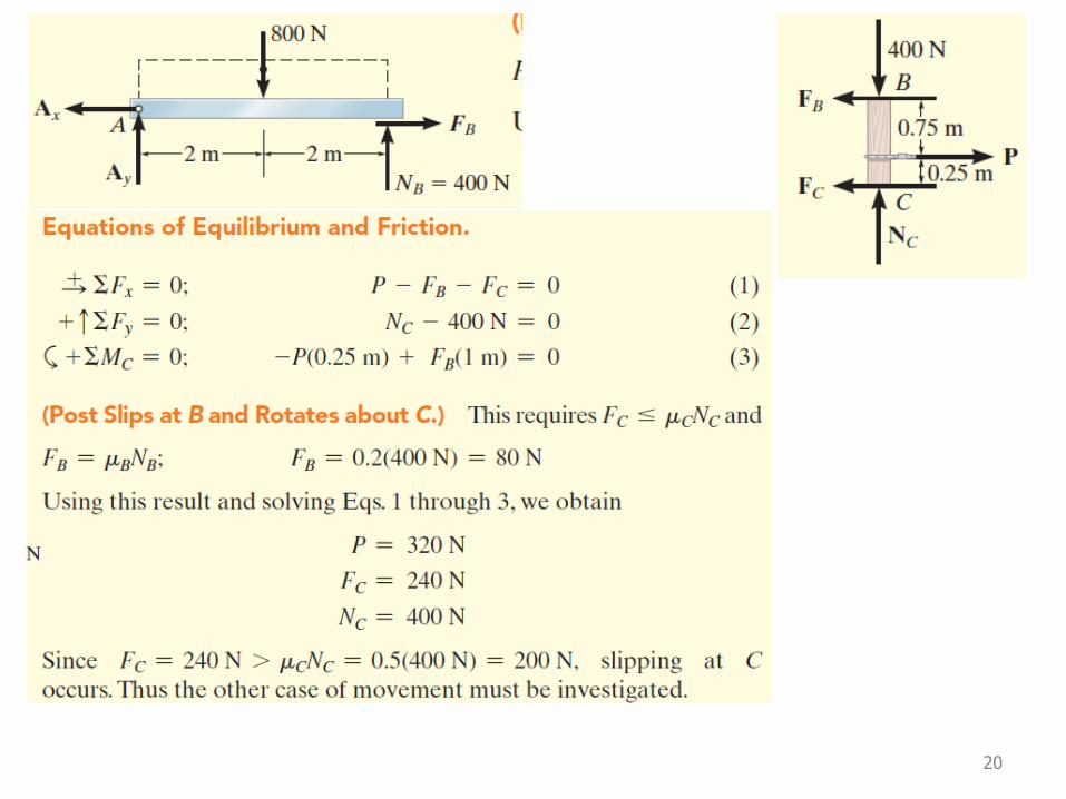
20

21
22
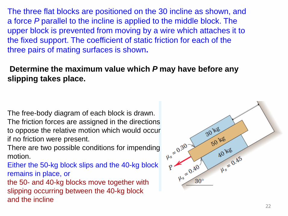
The three flat blocks are positioned on the 30 incline as shown, and
a force P parallel to the incline is applied to the middle block. The
upper block is prevented from moving by a wire which attaches it to
the fixed support. The coefficient of static friction for each of the
three pairs of mating surfaces is shown.
Determine the maximum value which P may have before any
slipping takes place.
The free-body diagram of each block is drawn.
The friction forces are assigned in the directions
to oppose the relative motion which would occur
if no friction were present.
There are two possible conditions for impending
motion.
Either the 50-kg block slips and the 40-kg block
remains in place, or
the 50- and 40-kg blocks move together with
slipping occurring between the 40-kg block
and the incline
23
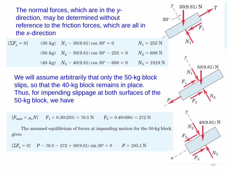
The normal forces, which are in the y-
direction, may be determined without
reference to the friction forces, which are all in
the x-direction
We will assume arbitrarily that only the 50-kg block
slips, so that the 40-kg block remains in place.
Thus, for impending slippage at both surfaces of the
50-kg block, we have
24
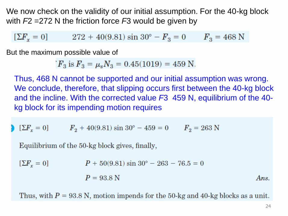
We now check on the validity of our initial assumption. For the 40-kg block
with F2 =272 N the friction force F3 would be given by
But the maximum possible value of
Thus, 468 N cannot be supported and our initial assumption was wrong.
We conclude, therefore, that slipping occurs first between the 40-kg block
and the incline. With the corrected value F3 459 N, equilibrium of the 40-
kg block for its impending motion requires
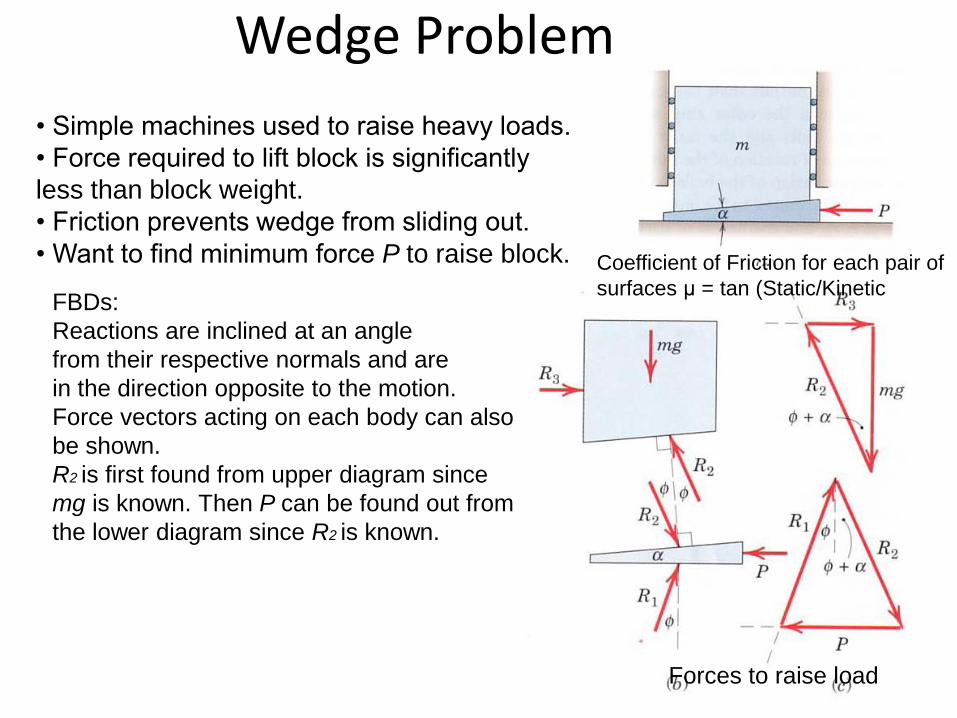
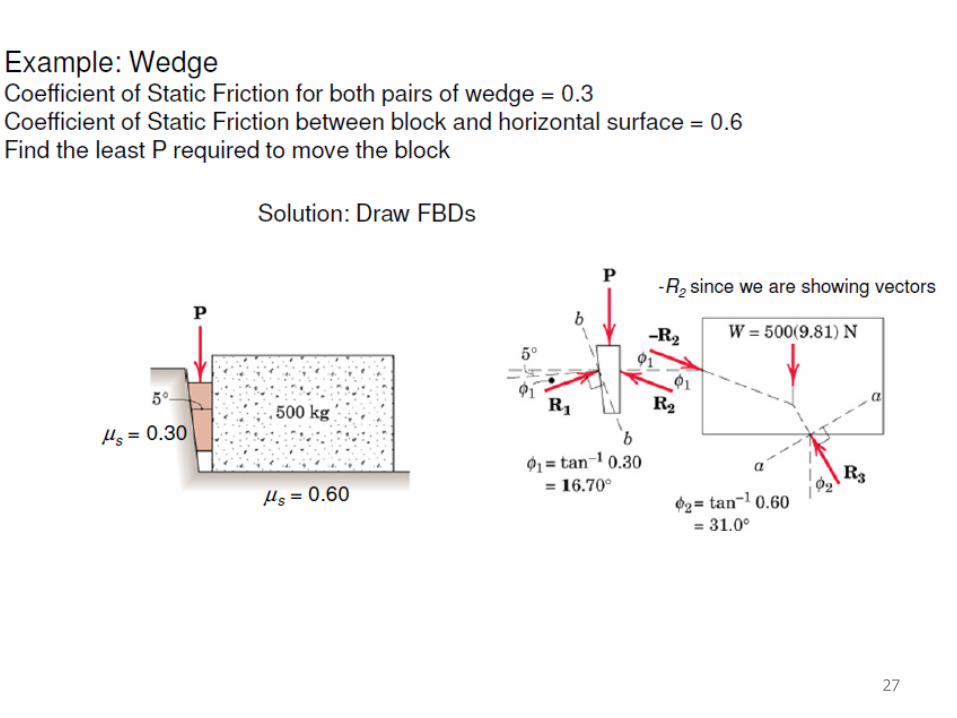
Wedge Problem
25
• Simple machines used to raise heavy loads.
• Force required to lift block is significantly
less than block weight.
• Friction prevents wedge from sliding out.
• Want to find minimum force P to raise block.
FBDs:
Reactions are inclined at an angle
from their respective normals and are
in the direction opposite to the motion.
Force vectors acting on each body can also
be shown.
R2 is first found from upper diagram since
mg is known. Then P can be found out from
the lower diagram since R2 is known.
Forces to raise load
Coefficient of Friction for each pair of
surfaces μ = tan (Static/Kinetic

26
P is removed and wedge remains in place
Equilibrium of wedge requires that the equal reactions R1 and R2 be collinear.In the figure, wedge angle α is taken to be less than Impending slippage at the upper
surface Impending slippage at the lower surface
Slippage must occur at both surfaces simultaneously In order for the wedge to slide out of its space, Else, the wedge is Self-LockingRange of angular positions of R1 and R2 for which the wedge will remain in place is shown in figure (b)
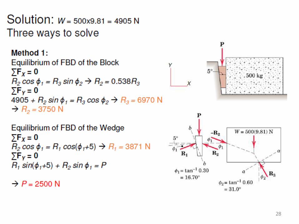
27
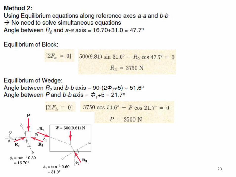
28
29
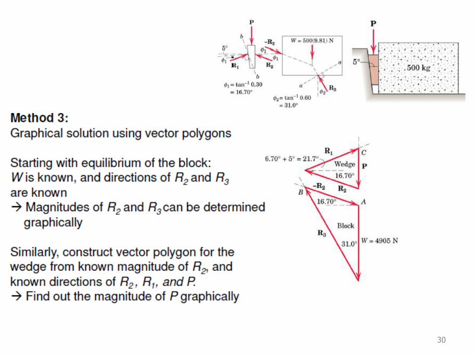
30
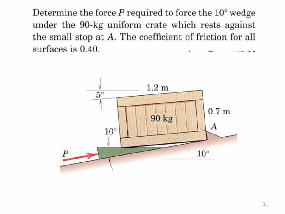
31
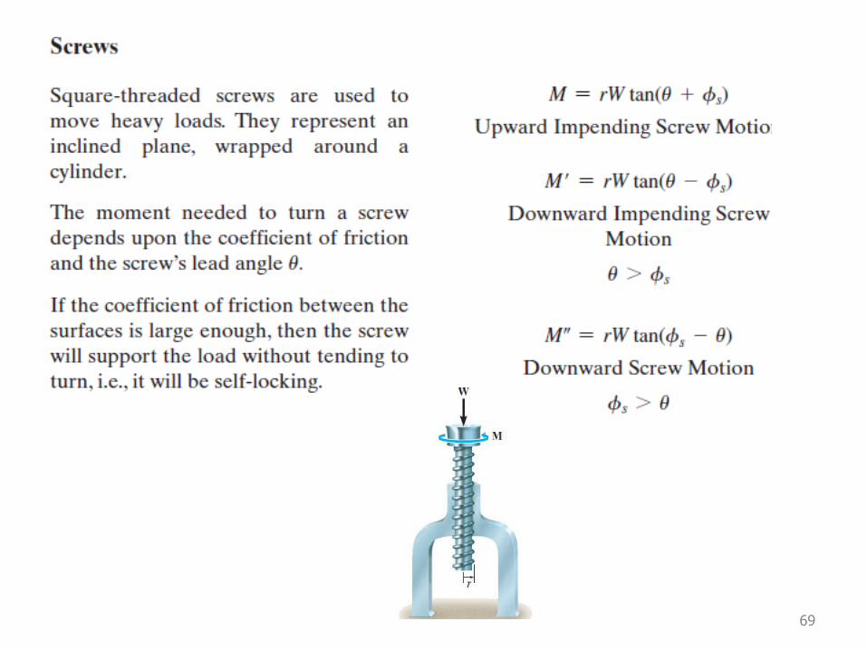
Screw
32
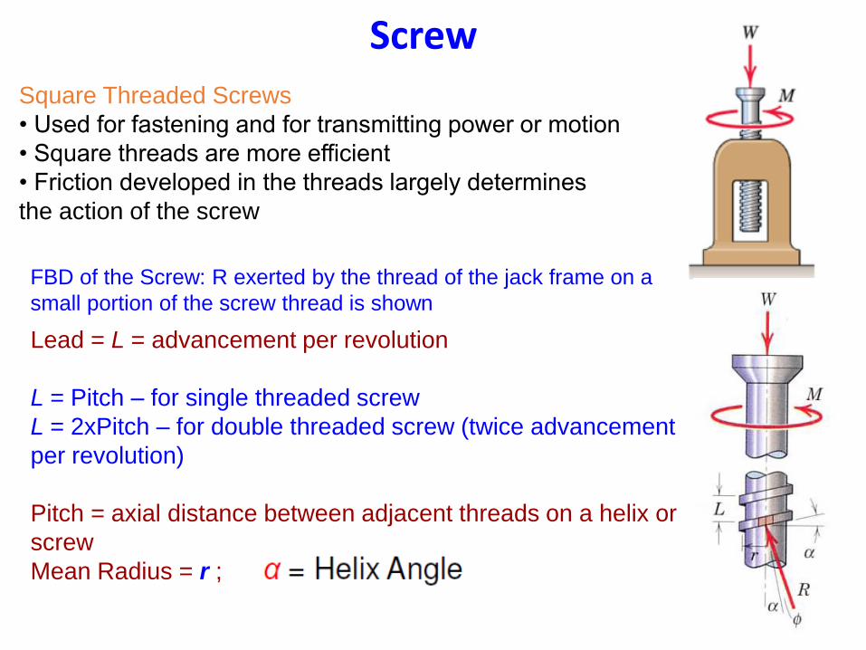
Square Threaded Screws
• Used for fastening and for transmitting power or motion
• Square threads are more efficient
• Friction developed in the threads largely determines
the action of the screw
FBD of the Screw: R exerted by the thread of the jack frame on a
small portion of the screw thread is shown
Lead = L = advancement per revolution
L = Pitch – for single threaded screw
L = 2xPitch – for double threaded screw (twice advancement
per revolution)
Pitch = axial distance between adjacent threads on a helix or
screw
Mean Radius = r ;
33
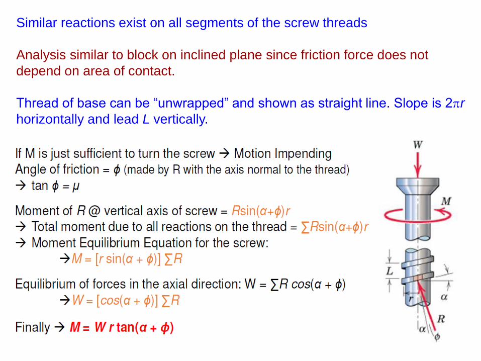
Similar reactions exist on all segments of the screw threads
Analysis similar to block on inclined plane since friction force does not
depend on area of contact.
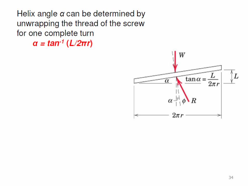
Thread of base can be “unwrapped” and shown as straight line. Slope is 2pr
horizontally and lead L vertically.
34
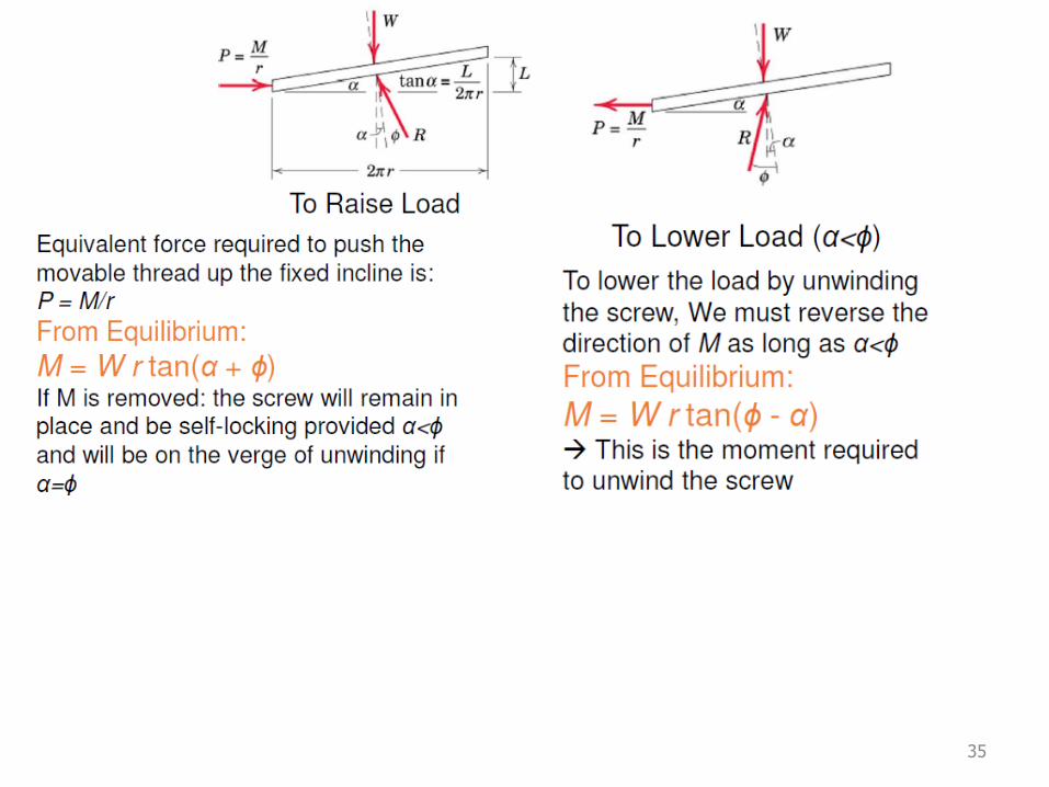
35
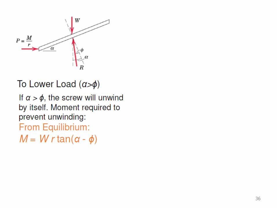
36
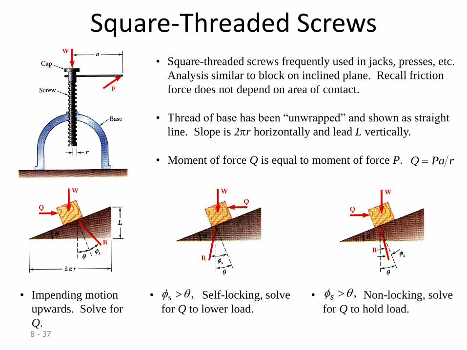
8 - 37
Square-Threaded Screws• Square-threaded screws frequently used in jacks, presses, etc.
Analysis similar to block on inclined plane. Recall friction
force does not depend on area of contact.
• Thread of base has been “unwrapped” and shown as straight
line. Slope is 2pr horizontally and lead L vertically.
• Moment of force Q is equal to moment of force P. rPaQ
• Impending motion
upwards. Solve for
Q.
• Self-locking, solve
for Q to lower load.
, s • Non-locking, solve
for Q to hold load.
, s
8 - 38
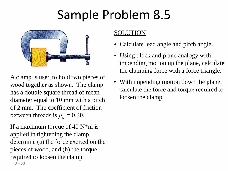
Sample Problem 8.5
A clamp is used to hold two pieces of
wood together as shown. The clamp
has a double square thread of mean
diameter equal to 10 mm with a pitch
of 2 mm. The coefficient of friction
between threads is s = 0.30.
If a maximum torque of 40 N*m is
applied in tightening the clamp,
determine (a) the force exerted on the
pieces of wood, and (b) the torque
required to loosen the clamp.
SOLUTION
• Calculate lead angle and pitch angle.
• Using block and plane analogy with
impending motion up the plane, calculate
the clamping force with a force triangle.
• With impending motion down the plane,
calculate the force and torque required to
loosen the clamp.
8 - 39
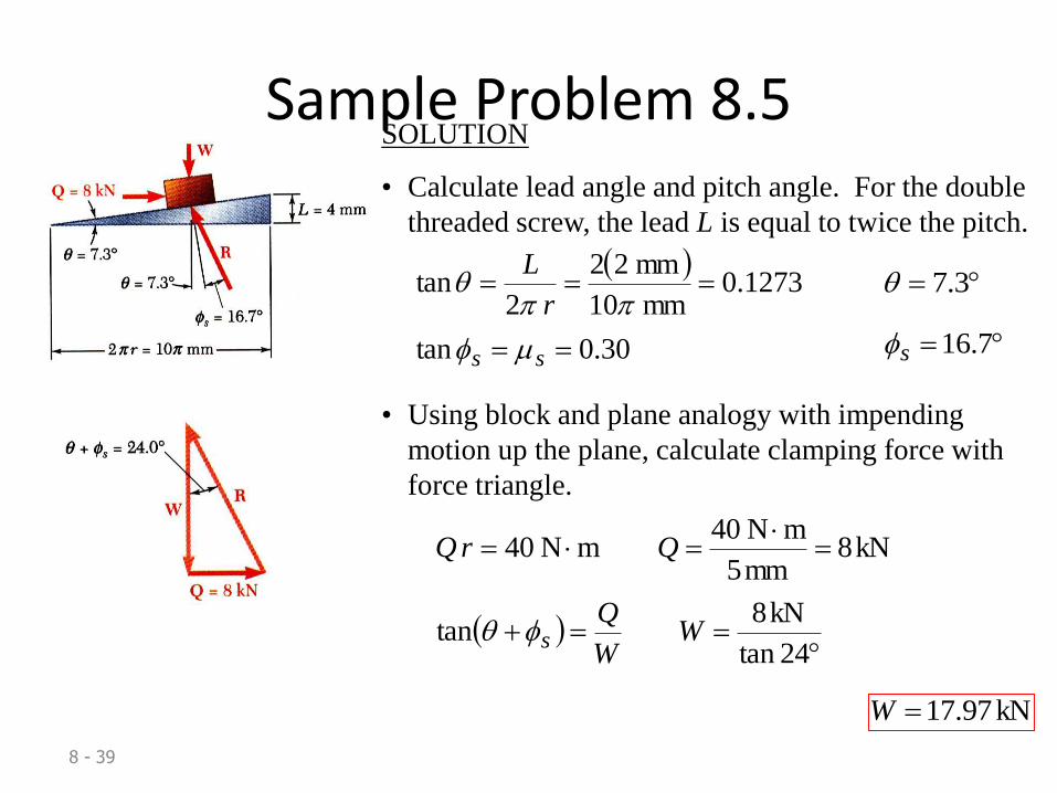
Sample Problem 8.5SOLUTION
• Calculate lead angle and pitch angle. For the double
threaded screw, the lead L is equal to twice the pitch.
30.0tan
1273.0mm 10
mm22
2tan
ss
r
L
pp 3.7
7.16s
• Using block and plane analogy with impending
motion up the plane, calculate clamping force with
force triangle.
kN8mm5
mN 40mN 40
QrQ
24tan
kN8tan W
W
Qs
kN97.17W

8 - 40
Sample Problem 8.5• With impending motion down the plane, calculate
the force and torque required to loosen the clamp.
4.9tankN97.17tan QW
Qs
kN975.2Q
m105N10975.2
mm5kN975.2
33
rQTorque
mN87.14 Torque
41
42
8 - 43
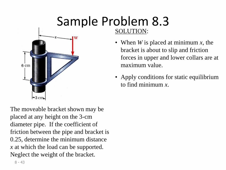
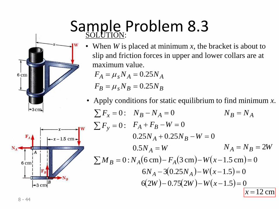
Sample Problem 8.3
The moveable bracket shown may be
placed at any height on the 3-cm
diameter pipe. If the coefficient of
friction between the pipe and bracket is
0.25, determine the minimum distance
x at which the load can be supported.
Neglect the weight of the bracket.
SOLUTION:
• When W is placed at minimum x, the
bracket is about to slip and friction
forces in upper and lower collars are at
maximum value.
• Apply conditions for static equilibrium
to find minimum x.
8 - 44
Sample Problem 8.3SOLUTION:
• When W is placed at minimum x, the bracket is about to
slip and friction forces in upper and lower collars are at
maximum value.
BBsB
AAsA
NNF
NNF
25.0
25.0
• Apply conditions for static equilibrium to find minimum x.
:0 xF 0 AB NN AB NN
:0 yF
WN
WNN
WFF
A
BA
BA
5.0
025.025.0
0
WNN BA 2
:0 BM
05.1275.026
05.125.036
0cm5.1cm3cm6
xWWW
xWNN
xWFN
AA
AA
cm12x
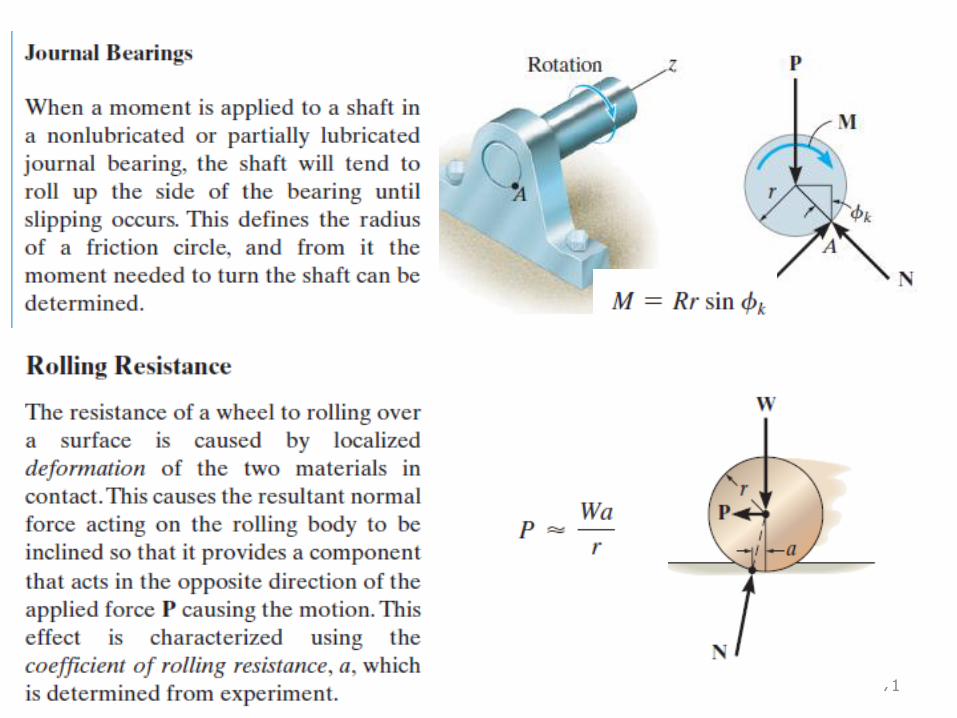
8 - 45
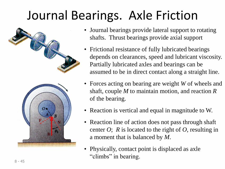
Journal Bearings. Axle Friction• Journal bearings provide lateral support to rotating
shafts. Thrust bearings provide axial support
• Frictional resistance of fully lubricated bearings
depends on clearances, speed and lubricant viscosity.
Partially lubricated axles and bearings can be
assumed to be in direct contact along a straight line.
• Forces acting on bearing are weight W of wheels and
shaft, couple M to maintain motion, and reaction R
of the bearing.
• Reaction is vertical and equal in magnitude to W.
• Reaction line of action does not pass through shaft
center O; R is located to the right of O, resulting in
a moment that is balanced by M.
• Physically, contact point is displaced as axle
“climbs” in bearing.
8 - 46
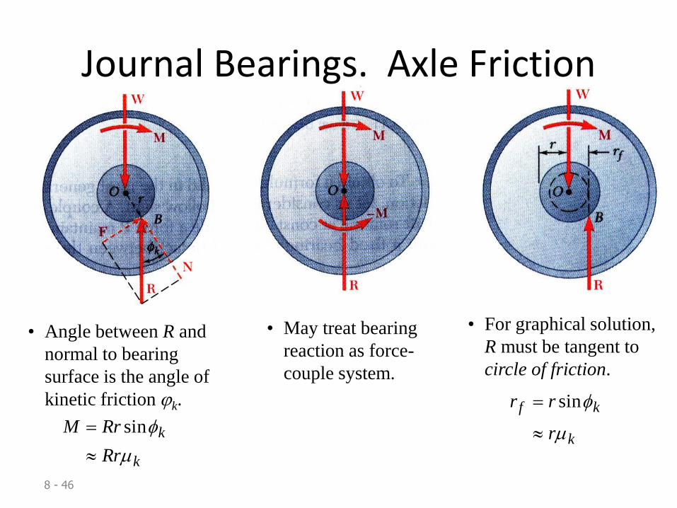
Journal Bearings. Axle Friction
• Angle between R and
normal to bearing
surface is the angle of
kinetic friction jk.
k
k
Rr
RrM
sin
• May treat bearing
reaction as force-
couple system.
• For graphical solution,
R must be tangent to
circle of friction.
k
kf
r
rr
sin
47
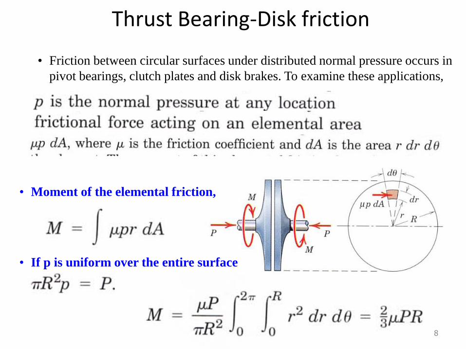
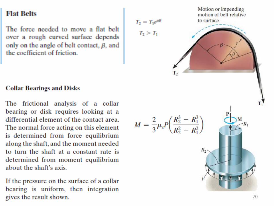
Thrust Bearing-Disk friction
48
• Friction between circular surfaces under distributed normal pressure occurs in
pivot bearings, clutch plates and disk brakes. To examine these applications,
• Moment of the elemental friction,
• If p is uniform over the entire surface
49
50

51
52
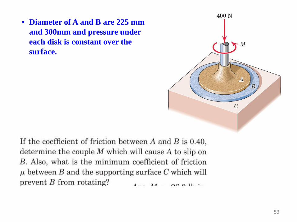
53
• Diameter of A and B are 225 mm
and 300mm and pressure under
each disk is constant over the
surface.
54
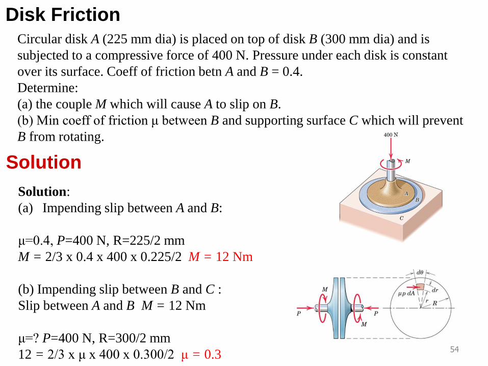
Disk Friction
Circular disk A (225 mm dia) is placed on top of disk B (300 mm dia) and is
subjected to a compressive force of 400 N. Pressure under each disk is constant
over its surface. Coeff of friction betn A and B = 0.4.
Determine:
(a) the couple M which will cause A to slip on B.
(b) Min coeff of friction μ between B and supporting surface C which will prevent
B from rotating.
Solution:
(a) Impending slip between A and B:
μ=0.4, P=400 N, R=225/2 mm
M = 2/3 x 0.4 x 400 x 0.225/2 M = 12 Nm
(b) Impending slip between B and C :
Slip between A and B M = 12 Nm
μ=? P=400 N, R=300/2 mm
12 = 2/3 x μ x 400 x 0.300/2 μ = 0.3
Solution
55
56
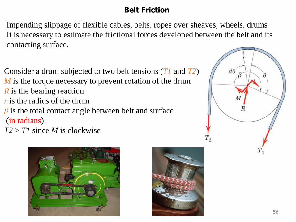
Belt Friction
Impending slippage of flexible cables, belts, ropes over sheaves, wheels, drums
It is necessary to estimate the frictional forces developed between the belt and its
contacting surface.
Consider a drum subjected to two belt tensions (T1 and T2)
M is the torque necessary to prevent rotation of the drum
R is the bearing reaction
r is the radius of the drum
β is the total contact angle between belt and surface
(in radians)
T2 > T1 since M is clockwise
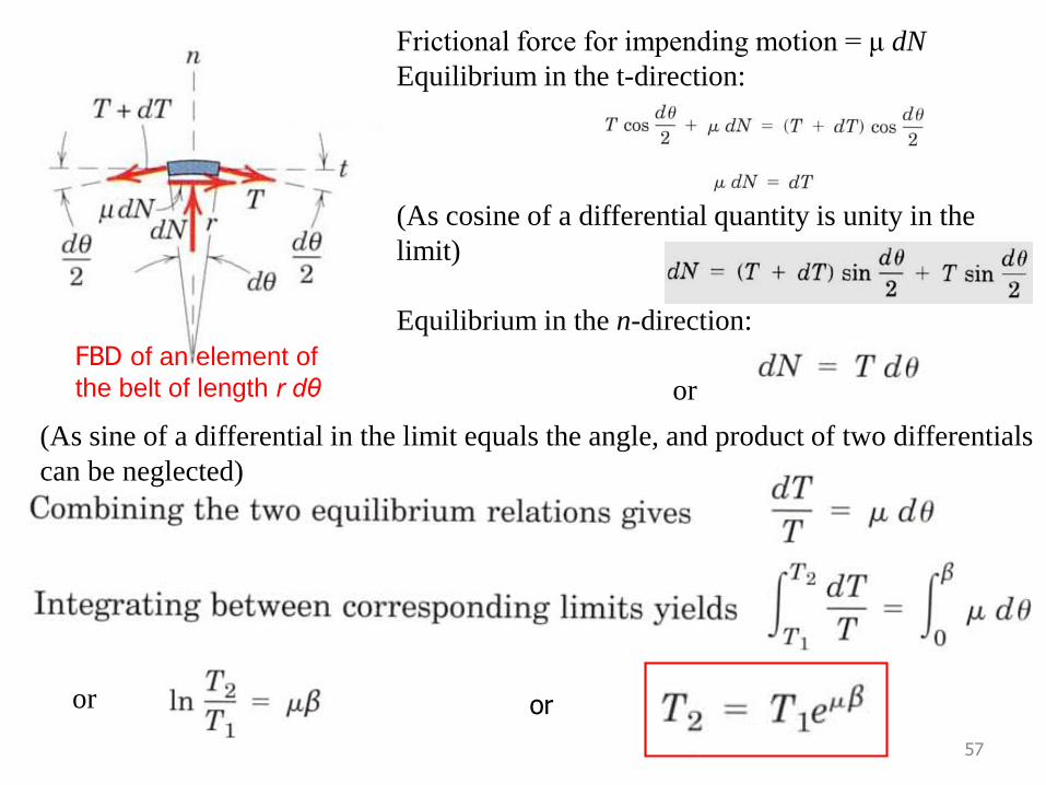
Frictional force for impending motion = μ dN
Equilibrium in the t-direction:
or
(As cosine of a differential quantity is unity in the
limit)
Equilibrium in the n-direction:
or
57
FBD of an element of
the belt of length r dθ
(As sine of a differential in the limit equals the angle, and product of two differentials
can be neglected)
or or
58
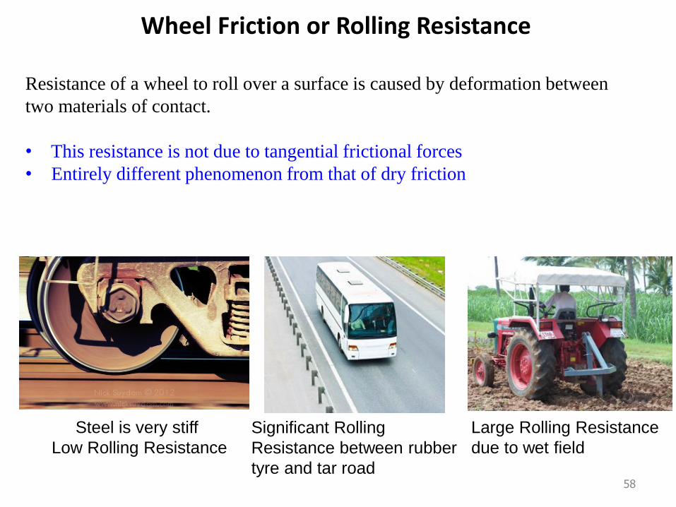
Wheel Friction or Rolling Resistance
Resistance of a wheel to roll over a surface is caused by deformation between
two materials of contact.
• This resistance is not due to tangential frictional forces
• Entirely different phenomenon from that of dry friction
Steel is very stiff
Low Rolling Resistance
Significant Rolling
Resistance between rubber
tyre and tar road
Large Rolling Resistance
due to wet field
59
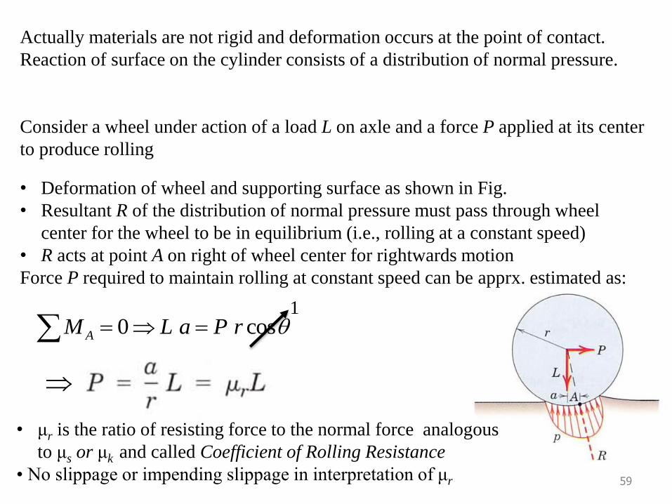
Actually materials are not rigid and deformation occurs at the point of contact.
Reaction of surface on the cylinder consists of a distribution of normal pressure.
Consider a wheel under action of a load L on axle and a force P applied at its center
to produce rolling
• Deformation of wheel and supporting surface as shown in Fig.
• Resultant R of the distribution of normal pressure must pass through wheel
center for the wheel to be in equilibrium (i.e., rolling at a constant speed)
• R acts at point A on right of wheel center for rightwards motion
Force P required to maintain rolling at constant speed can be apprx. estimated as:
10 cosAM L a P r
• μr is the ratio of resisting force to the normal force analogous
to μs or μk and called Coefficient of Rolling Resistance
• No slippage or impending slippage in interpretation of μr
60
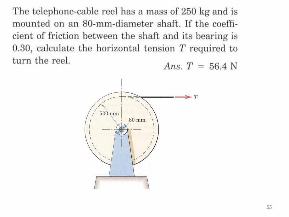
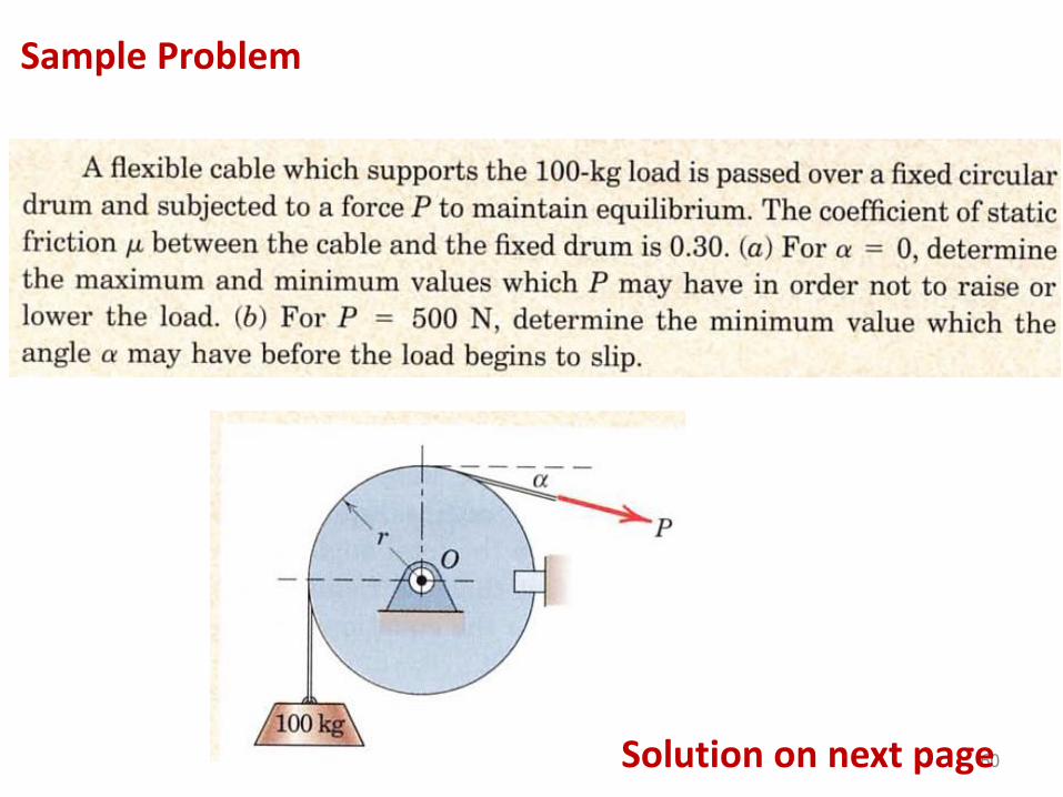
Sample Problem
Solution on next page
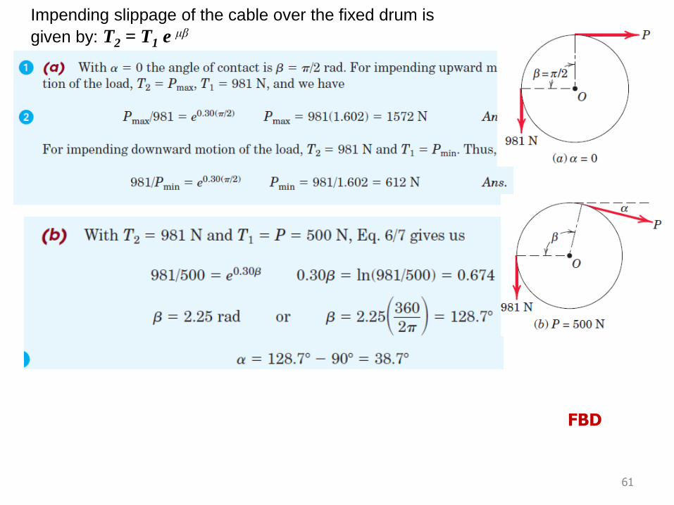
61
FBD
Impending slippage of the cable over the fixed drum is
given by: T2 = T1 e μβ
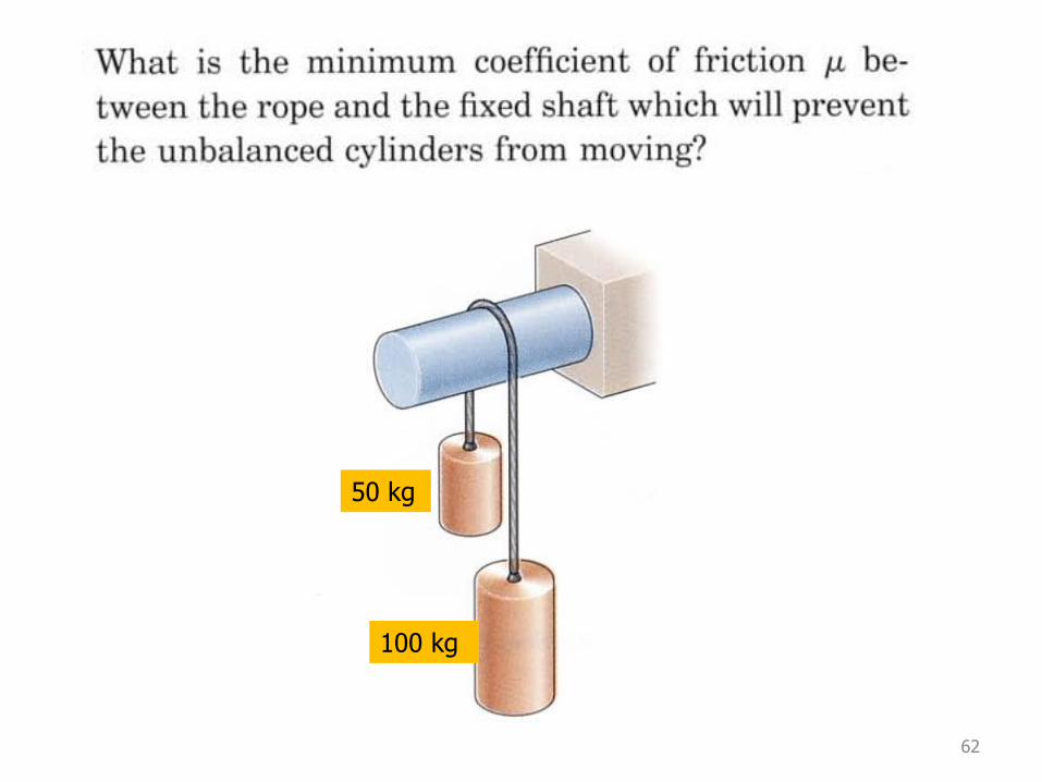
62
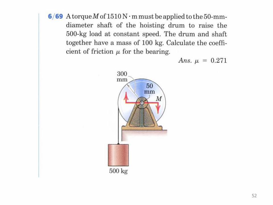
50 kg
100 kg
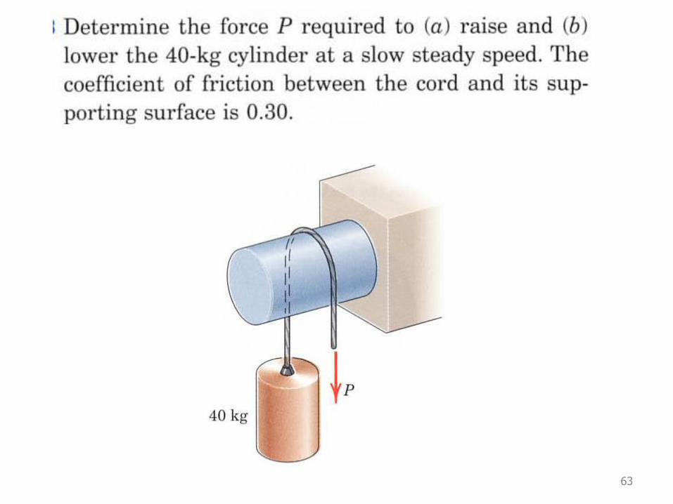
63
64
65
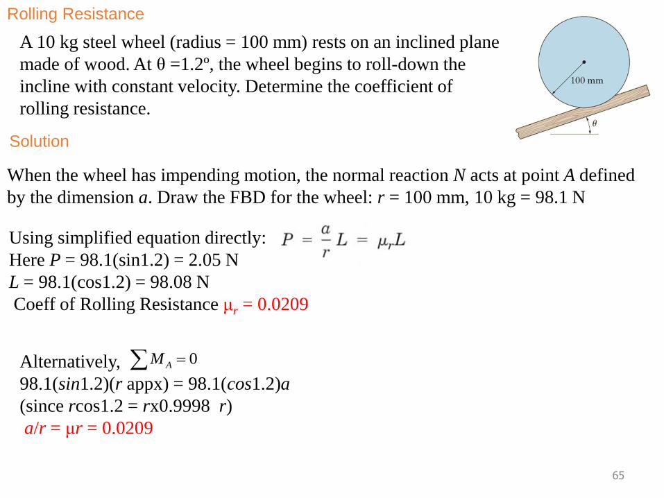
Rolling Resistance
A 10 kg steel wheel (radius = 100 mm) rests on an inclined plane
made of wood. At θ =1.2º, the wheel begins to roll-down the
incline with constant velocity. Determine the coefficient of
rolling resistance.
When the wheel has impending motion, the normal reaction N acts at point A defined
by the dimension a. Draw the FBD for the wheel: r = 100 mm, 10 kg = 98.1 N
Solution
Using simplified equation directly:
Here P = 98.1(sin1.2) = 2.05 N
L = 98.1(cos1.2) = 98.08 N
Coeff of Rolling Resistance μr = 0.0209
Alternatively,
98.1(sin1.2)(r appx) = 98.1(cos1.2)a
(since rcos1.2 = rx0.9998 r)
a/r = μr = 0.0209
0AM
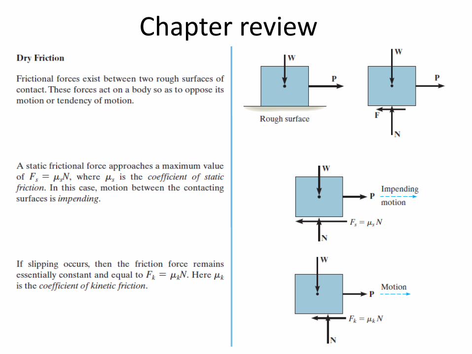
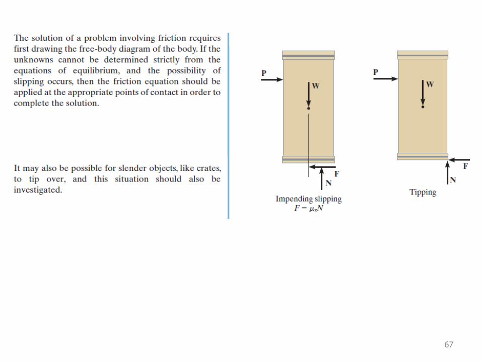
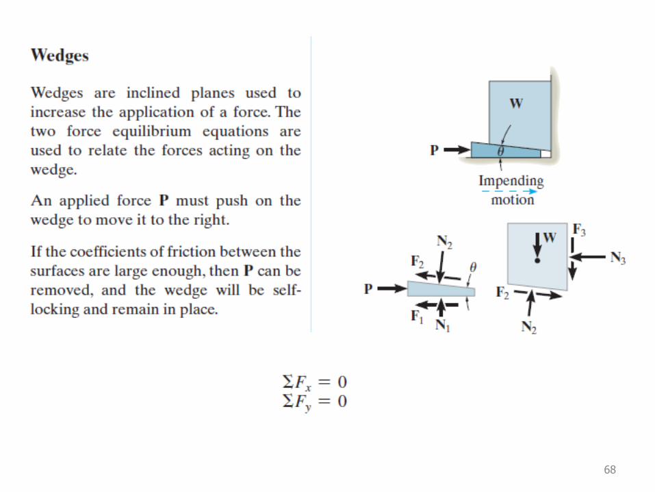
Chapter review
66
67
68
69
70
71