Embed Size (px)
Citation preview

Static Analysis of Tall Buildings with Combined System of Framed Tube, Shear
Core, Outrigger and Belt Truss Seyed Mozafar Davari1, Mohsen Malekinejad2*, Reza Rahgozar3
1Ph.D. Candidate, Civil Engineering Department, Sirjan Branch, Islamic Azad University, Sirjan, Iran [email protected]
2Assistant Professor, Civil Engineering Department, Sirjan Branch, Islamic Azad University, Sirjan, Iran Young Researchers and Elite Club, Sirjan Branch, Islamic Azad University, Sirjan, Iran.
[email protected] 3Professor, Civil Engineering Department, Shahid Bahonar University of Kerman, Kerman, Iran
Abstract-In this paper, behaviour of tall structures with combined system of framed tube, shear core and outrigger-belt truss is investigated using continuum approach. Framed tube structure and shear core against lateral loads acts as a cantilever beam and the effect of outrigger and belt truss on the shear core are considered as a torsional spring in the position of outrigger-belt truss system at the height of the structure. The torsion spring acts in the opposite direction due to applied loads and reduces displacement and axial force of the structure at of bottom. Using compatibility relations of different parts of the combined system and replacing them in Euler–Bernoulli’s theory and Timoshenko's theory, and applying boundary conditions, the displacement of floors and roof is obtained. The validity and effectiveness of the proposed method are examined using numerical examples and those obtained from computer analysis.
Keyword-Framed Tube, Outrigger and Belt Truss, Euler–Bernoulli’s Beam, Timoshenko's Beam, Shear deformation.
I. INTRODUCTION
In recent years, in Iran, as in other countries, tall buildings construction in cities has been taken into account in the context of population based on policies and land shortages. Today, construction is taking place for taller buildings, especially in major cities, and one of the most important issues in tall structures is choosing the suitable structural form sustaining of lateral loads. The susceptibility of tall structures to lateral loads is far greater than gravity loads and if the height of the structure increased, the conventional methods for resisting these structures are not enough. One of the most applied structural systems for tall structures is outrigger and belt truss in tall structures to reduce structure deformations and resistance to lateral loads. Outrigger and belt truss connects external columns to the inner shear core. As a result, the set of external columns and outrigger resists against the shear core rotation, reducing the lateral deformations and reducing the momentum on the structure's bottom. Addition to columns at end of the outriggers, usually other peripheral columns are also used to fix the outriggers. This type of structural form is outrigger and belt truss [1].Several methods have been proposed for analysing framed tubes. Coull and Bose presented a method based on theory of elasticity. In this method, the structure is modelled as equivalent orthotropic plates, and the equilibrium and compatibility equations are satisfied in the equivalent structure [2]. Coull and Ahmed presented a method for obtaining deflection of the framed tube [3]. Using equivalent orthotropic plates, energy relations and the relations of the theory of elasticity. Kwan provided equations for determining the stress in the columns, as well as obtaining lateral displacements of framed tube structure [4]. Connor and Pouangare proposed a five-member vertical method in which the structure is equated to vertical beams and vertical plates. By calculating the shear and bending stiffness of the members, relations are obtained for stresses in the columns [5]. Another way to improve the behaviour of framed tube is to add internal framed tubes to the original structure. In this case, distribution of stress and displacement can be significantly adjusted. Also, several other methods for analysing framed tubes have been presented by researchers such as Paulino [6], Mahjoub et al. [7]. Kamgar and Rahgozar studied vibration of tall structures using analytical methods [8]. Jahanshahi and Rahgozar determined the best position of a belt in a combined framed tube system using energy method [9]. Malekinejad and Rahgozar investigated free vibration analysis of tall structures that has a framed tube system [10]. In addition, Ramezani et al. conducted their research on analysis of non-uniform tall building structures considering axial force effects [11]. Tavakoli et al. evaluated the soil-structure interaction of outrigger-belt truss system of high-rise structures under seismic demand criteria [12]. Kim et al. studied optimization usage of outriggers in tall buildings in order to diminish lateral displacement and di�erential axial shortening [13].A dimensionless formula has been developed for flexural stiffness of tall buildings with objective of optimization problem by Alavi et al. in 2017 [14]. Kamgar and Rahgozar proposed a method for reducing the static roof displacement and axial forces in the
ISSN (Print) : 2319-8613 ISSN (Online) : 0975-4024 Seyed Mozafar Davari et al. / International Journal of Engineering and Technology (IJET)
DOI: 10.21817/ijet/2019/v11i5/191105003 Vol 11 No 5 Oct-Nov 2019 1071

columns displacemobtained.
A tall attached load, thebecome a
Fig. 1.
In thisoutriggeruniform adesign to
In thiassumpti
1) Jo
2) Co
3) Ouand belt t
4) Aheight of
5) Sh
6) A
III.
The usresistanceresult, thdisplacemcore is moutriggerdistribute
of high-risement of floor.
II. COMB
structure witto the outer c
e outriggers pra less compare
a) Structure with
s section, an ars with similarand their verti
o estimate the
is section, stons:
ints of outrigg
onnection of o
utrigger and btruss are ignor
Axial stiffnessf the structure.
hear core at bo
Analysis metho
ANALYTICAL
se of outriggee to lateral lo
he set of exterments and momodeled as a cr on the main ed lateral load
e buildings rs and roof o
BINED SYSTEM
th outriggers iolumns by therevent rotatioed to unbraced
altered outrigger
approximate ar dimensions ical members approximate d
tructural disp
gers are pinne
outriggers to s
belt truss are qred).
s of periphery.
ottom of the s
od of the struc
L MODELLING
er and belt truoads. Outriggrnal columns omentum at thcantilever beastructure acts
ding, the angle
[15]. In thisf combined s
M OF FRAMED
includes a reie horizontal ca
on of the cored state (Fig. 1
r subjected to late
analysis methat each level change in dim
displacements
placement is
edto outer colu
shear core is ri
quite rigid and
y columns and
structure is qu
ctureassumes b
G OF COMBINE
BASEDON E
uss in tall strucer with belt tand outrigger
he structure’s am. Outriggers as a spring. e of rotation of
s paper, usinsystem of fram
TUBE, SHEAR
inforced concantilever. Whe and cause la).
eral loads; b) Resu
hod for structuis introduced
mensional altis and forces.
obtainedusing
umns and only
igid.
d prevent entir
dmomentum o
uite rigid and f
be linear elast
ED SYSTEM W
EULER–BERN
ctures is very truss connectsr resists againbottom. A ta
r and belt trusAs shown in
f the beam at p
ng Euler–Bermed tube, sh
R CORE AND O
rete shear corhen the buildinateral displace
ultant of displace
ures with unif.Although cotudes, this ana
g an outrigg
y will transfer
re torsion of t
of the core ine
fixed.
tic.
ITH ONE RIGI
NOULLI THEOR
common in rs external colnst the shear call structure wss is controlleFig. 2, if thi
point x is equ
rnoulli and hear core and
OUTRIGGER-BE
re or a bracedng is under theements and m
ements; c) Resulta
form outriggeonventional stralytical metho
ger and belt
axial forces.
the structure (f
ertia are const
ID OUTRIGGER
RY
reducing struclumns to the core rotation
with a framed ed along the ss set is to be al to θx.
Timoshenko’outrigger-bel
ELT TRUSS
d steel frame,e effects of a hmoments of th
ant of core mome
er, cores, coluructures are nod can be used
truss, with
flexibility of o
tant and unifo
R AND BELT T
ctural displaceinner shear cand reduces ttube system
structure and subjected to u
s theory, lt truss is
, which is horizontal he core to
ents [14]
umns, and ot usually d in initial
following
outriggers
orm along
TRUSS
ement and core. As a the lateral and shear effects of uniformly
ISSN (Print) : 2319-8613 ISSN (Online) : 0975-4024 Seyed Mozafar Davari et al. / International Journal of Engineering and Technology (IJET)
DOI: 10.21817/ijet/2019/v11i5/191105003 Vol 11 No 5 Oct-Nov 2019 1072

Given 3, this mo
Assum
Whereas:
And:
The ab
according
without
Fig. 2. St
the rigidity ooment become
ming that the c
e δ is degree o
bove relations
g to Fig. 2, b
spring and x
tructural analytica
of the outriggees a force cou
cross-sectiona
of axial deform
Fig
ship shows th
based on supe
2 obtained fro
al model of outrig
er and pinned upler in the ou
M
l area of the o
P
mation of oute
K
g. 3. Torsion spri
hat spring stif
erposition pri
om moment,M
x
1
1x EI
gger subjected to
connection outer columns:
M Pd
outer columns
AE
x
er columns and
2x d
2
2
AEd
x
ing moment matc
ffness is a fun
inciple, the su
M, due to the s
1 2x x
00
x
x xM d
loading based on
f the outrigge
is constant at
d given the sm
ching with force c
nction of pos
um 1x is resu
spring:
0
n Euler-Bernoulli
er to outer colu
(1)
t height of the
(2)
mall angle of r
(3)
(4)
coupler
ition of the s
ultant of a co
(5)
(6)
i’s method
umns, as show
structure:
rotation of the
pring. To cal
oncentrated la
wn in Fig.
e outrigger,
lculate x
ateral load
ISSN (Print) : 2319-8613 ISSN (Online) : 0975-4024 Seyed Mozafar Davari et al. / International Journal of Engineering and Technology (IJET)
DOI: 10.21817/ijet/2019/v11i5/191105003 Vol 11 No 5 Oct-Nov 2019 1073

As can be seen, considering original coordinates at support, 0 0 and the relation xM as shown inFig. 2 is:
2 2
2 2x
qL qxM qLx
(7)
Consequently, usingEquation (6): 2 2 3
1
1
2 2 6x
qL x qLx qx
EI
(8)
To calculate 2x from the moment xM ,we will:
2x
x
K x
EI
(9)
As a result: 2 2 31
2 2 6x
x
K xqL x qLx qx
EI EI
(10)
Equation (10) can also be written as follows: 2 2 3
2 2 6x
qL x qLx qx
EI Kx
(11)
In above relation,q is the intensity of the lateral load, Mis moment at x point, E is modulus of elasticity of the braced shear core, I is moment of inertia of the structure, A is cross section of the peripheral columns in the structure, L is height of the structure, and d is distance between outer columns and K is calculated from Equation (4).
Displacement is also obtained according to superposition principle, including displacement due to loading of the structure, 1( )y x , and displacement due to the presence of a spring, 2 ( )y x , which are calculated according
to the following relations. 2 2 3 4
1( )4 6 24
q L x Lx xy x
EI
(12)
2
2
, 02( )(2 )
,2
Mxx a
EIy xMa x a
a x LEI
(13)
xM K (14)
And finally, total displacement is equal to:
1 2( ) ( ) ( )y x y x y x (15)
IV. MODELLING OF RIGID OUTRIGGER AND BELT TRUSS SYSTEM BASED ON TIMOSHENKO’S THEORY
In the previous section, using Euler-Bernoulli method, displacement of the structure can be calculated at any desired point, but in this method, the shear effect is ignored. However, in Timoshenko’s beam theory, effects of shear are taken into account and the relations are modified as follows.
To calculate x as shown in Fig. 4, using superposition principle, x will be equal to the sum of 1x from the
concentrated lateral load without spring, and 2x resulting from the moment,M, due to the spring and 3xresulting from the shear effects:
1 2 3x x x x (16)
ISSN (Print) : 2319-8613 ISSN (Online) : 0975-4024 Seyed Mozafar Davari et al. / International Journal of Engineering and Technology (IJET)
DOI: 10.21817/ijet/2019/v11i5/191105003 Vol 11 No 5 Oct-Nov 2019 1074

Fig. 4
In thecolumns bending result, in
into acco
As a re
The am
and the v
The as
1) Eac
2) The
3) The
As can
4. An analytical m
case of a share not tensimode, due to
n the compatib
ount.
Fig. 5. Co
esult, the valu
mount of 1x
value of 2x r
ssumptions us
ch plate remain
e cross section
e stress-strain
n be seen, the
model of the struc
hear deformationed or compo change in lebility relations
omparison of bend
ue of x is equ
obtained from
resulting from
sed in Timoshe
ns as a plate.
n of beams is c
relationship f
condition of p
cture with an outr
tion, floors arpressed and t
ength of the ps, the effect o
ding and shear de
ual to:
x
m a distributed
m the moment,M
enko’s theory
constant and s
follows Hooke
plate’s perpen
rigger subjected t
re displaced ithus do not p
peripheral coluof shear ( 3x )
eformation a) Ben
1 2x x
d lateral load
M, due to the
y are as follow
symmetrical.
e’s law.
ndicularity is r
to a uniformly dis
in parallel wiproduce equivumns, force is is not consid
nding deformation
without a spri
spring, is also
ws:
removed in Ti
stributed load by
ith each othervalent force ins created in thdered and only
n and b) Shear de
(17)
ing, as in Equ
o obtained as i
moshenko’s th
Timoshenko’s m
r so that the n the spring. he spring (Figy 1x and 2x
eformation.
uation (12), is
in Equation (1
heory beam (F
method
periphery While, in g. 5).As a are taken
obtained,
13).
Fig. 6).
ISSN (Print) : 2319-8613 ISSN (Online) : 0975-4024 Seyed Mozafar Davari et al. / International Journal of Engineering and Technology (IJET)
DOI: 10.21817/ijet/2019/v11i5/191105003 Vol 11 No 5 Oct-Nov 2019 1075

Regard
On the
Based
On the
To obt
This thconstant
Using
Using
ding the geom
e other hand, a
on Fig. 7, wh
e other hand:
tain shear stre
heory is morealtitude, the s
the bending m
Equations (20
metry of Fig. 6
according to H
hich displays t
Fig. 7.
ess according t
e accurate thanhear correctio
moment equili
0) and (24), be
Fig. 6. Deform
6, we have:
x
x
u z
du
dx
Hooke’s law:
the deformatio
x
. Geometry of De
xz
to xz xzG ,
xz
d
n Euler-Bernoon coefficient,
xz kG
ibrium:
xM
ending mome
mation of Timosh
( )
( )x
z x
u d xz
x dx
x xE
on of the beam
( )d xEz
dx
eformation in Tim
( )d
xdx
, we have:
( )d
x Gdx
oulli’s theory,,k, is used, as:
( )d
G xdx
xz dA
ent is obtained
henko’s beam.
)
m section and
moshenko’s beam
but as it con
d as follows:
(18)
(19)
using Equatio
(20)
mtheory.
(21)
(22)
siders the she
(23)
(24)
ons (18) and (1
ear strain distr
19):
ribution at
ISSN (Print) : 2319-8613 ISSN (Online) : 0975-4024 Seyed Mozafar Davari et al. / International Journal of Engineering and Technology (IJET)
DOI: 10.21817/ijet/2019/v11i5/191105003 Vol 11 No 5 Oct-Nov 2019 1076
On oth
Using
In abo[15]. A is
On the
If, in r
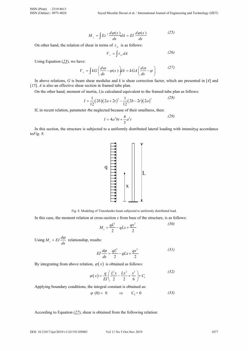
In thistoFig. 8.
In this
Using
By int
Apply
Accor
her hand, the r
Equation (23
ove relations, s also an effec
e other hand, m
recent relation
s section, the s
s case, the mom
x
dM EI
dx
tegrating from
ying boundary
ding to Equat
M
relation of she
), we have:
xV G is beam sh
ctive shear sec
moment of ine
I
n, parameter tb
structure is su
Fig. 8. Model
ment relation
relationship,
m above relatio
conditions, th
ion (27), shea
2x
dM Ez
ear in terms of
xV
dkG
dx
ear modulus action in framed
ertia, I,is calcu
12 2
12b a
be neglected b
4I
ubjected to a u
ing of Timoshenk
at cross-sectio
2x
qLM
results:
dEI
dx
on, x is ob
q Lx
EI
he integral con
(0) 0
ar is obtained f
( )xdA EI
dx
f xz is as foll
xz dA
( )x dA kGA
and k is sheard tube plan.
ulated equival
3 12 2
12t b
because of the
2 344
3a bt a t
uniformly dist
ko beam subjecte
on x from bas2 2
2 2
L qxqLx
2
2 2
qL qxqLx
btained as foll
2 2 3
2 2 6
L x Lx x
nstant is obtai
1 C
from the follo
( )d x
dx
lows:
dGA
dx
r correction fa
lent to the fram
32 2t a
ir smallness, t
tributed latera
ed to uniformly di
e of the struct2
2
2
x
lows:
3
16C
ined as:
1= 0
owing relation
(25)
(26)
(27)
actor, which a
med tube plan
(28)
then:
(29)
al loading with
istributed load.
ture, is as follo
(30)
(31)
(32)
(33)
:
are presented i
n as follows:
h intensityq ac
ows:
in [4] and
ccordance
ISSN (Print) : 2319-8613 ISSN (Online) : 0975-4024 Seyed Mozafar Davari et al. / International Journal of Engineering and Technology (IJET)
DOI: 10.21817/ijet/2019/v11i5/191105003 Vol 11 No 5 Oct-Nov 2019 1077

( )x
dV kGA x
dx
(34)
Using above relationship:
( )( )
d V xx
dx kGA
(35)
By integrating the above relation, results:
2
2 2 3
1
( ) ( )
22 2 6
V xx x dx dx
kGA
qxqLxq L x Lx x
x CEI kGA
(36)
Given the boundary conditions:
1(0) 0 C 0 (37)
As a result:
2
2 2 3 42
4 6 24
qxqLxq L x Lx x
xEI kGA
(38)
Equation (38) represents the relation 1 3( ) ( ) ( )y x y x y x .
In order to obtain the displacement, displacement caused by the loading of the structure 1( )y x is due to
presence of a spring 2 ( )y x and the displacement caused by the shear effect, 3 ( )y x , according to the
superposition principle, we have:
1 2 3( ) ( ) ( ) ( )y x y x y x y x (39)
Displacement due to presence of a spring is in accordance with Equation (13), and the displacement due to loading of the structure and the shear effect is obtained in accordance with Equation (38).
V. SOFTWARE ACHIEVEMENTS AND NUMERICAL REVIEWS
In this section, in order to investigate accuracy and efficiency of the proposed method, static analysis of tall buildings with a system of framed tube, shear core, outrigger and belt truss with symmetric plan was performed. The building is a 40-story concrete building modeled with SAP2000 software. All beams, columns, outrigger and belt truss have a value of 0.8( ) 0.8( )m m . Height of the floors is 3 m, thickness of the slab is 0.25 m, and
distance from the center to center of columns is 2.5 m. Modulus of elasticity and shear modulus are 20 GPa and 8 GPa, respectively. Shear core dimensions are equal to 5( ) 5( )m m and thickness of shear wall is equal to 0.25
m. The structure is subject to a uniformly distributed lateral load with intensity120 KN/m [4]. Fig. 9 and Fig. 10 presents model of the structure, which has been modeled in SAP2000.
ISSN (Print) : 2319-8613 ISSN (Online) : 0975-4024 Seyed Mozafar Davari et al. / International Journal of Engineering and Technology (IJET)
DOI: 10.21817/ijet/2019/v11i5/191105003 Vol 11 No 5 Oct-Nov 2019 1078

In FigBernoullimethod anorm of dobtained
Fig. 9. S
g. 11, compai’s beam theoabout 79% is displacement by Timoshen
Schematic model
Fig.
arison of storories for a 40-sdifferent withby the finite e
nko method.
of 40-story struc
10. The x-z view
ries displacemstory buildingh the second nelement metho
cture with outrigg
of the 40-story b
ment obtainedg is shown. Thnorm of displaod about 28%
ger and belt truss
building with outr
d by finite ehe second noracement by this different w
at middle of the s
rigger.
element methrm of displacehe Bernoulli m
with the second
structure.
hods, Timoshement by finitmethod, and thd norm of disp
enko and te element he second placement
ISSN (Print) : 2319-8613 ISSN (Online) : 0975-4024 Seyed Mozafar Davari et al. / International Journal of Engineering and Technology (IJET)
DOI: 10.21817/ijet/2019/v11i5/191105003 Vol 11 No 5 Oct-Nov 2019 1079
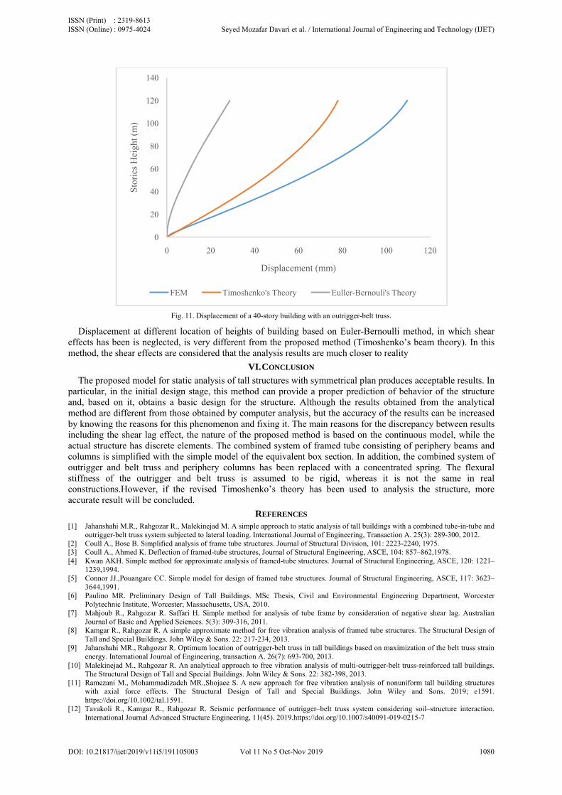
Fig. 11. Displacement of a 40-story building with an outrigger-belt truss.
Displacement at different location of heights of building based on Euler-Bernoulli method, in which shear effects has been is neglected, is very different from the proposed method (Timoshenko’s beam theory). In this method, the shear effects are considered that the analysis results are much closer to reality
VI. CONCLUSION
The proposed model for static analysis of tall structures with symmetrical plan produces acceptable results. In particular, in the initial design stage, this method can provide a proper prediction of behavior of the structure and, based on it, obtains a basic design for the structure. Although the results obtained from the analytical method are different from those obtained by computer analysis, but the accuracy of the results can be increased by knowing the reasons for this phenomenon and fixing it. The main reasons for the discrepancy between results including the shear lag effect, the nature of the proposed method is based on the continuous model, while the actual structure has discrete elements. The combined system of framed tube consisting of periphery beams and columns is simplified with the simple model of the equivalent box section. In addition, the combined system of outrigger and belt truss and periphery columns has been replaced with a concentrated spring. The flexural stiffness of the outrigger and belt truss is assumed to be rigid, whereas it is not the same in real constructions.However, if the revised Timoshenko’s theory has been used to analysis the structure, more accurate result will be concluded.
REFERENCES [1] Jahanshahi M.R., Rahgozar R., Malekinejad M. A simple approach to static analysis of tall buildings with a combined tube-in-tube and
outrigger-belt truss system subjected to lateral loading. International Journal of Engineering, Transaction A. 25(3): 289-300, 2012. [2] Coull A., Bose B. Simplified analysis of frame tube structures. Journal of Structural Division, 101: 2223-2240, 1975. [3] Coull A., Ahmed K. Deflection of framed-tube structures, Journal of Structural Engineering, ASCE, 104: 857–862,1978. [4] Kwan AKH. Simple method for approximate analysis of framed-tube structures. Journal of Structural Engineering, ASCE, 120: 1221–
1239,1994. [5] Connor JJ.,Pouangare CC. Simple model for design of framed tube structures. Journal of Structural Engineering, ASCE, 117: 3623–
3644,1991. [6] Paulino MR. Preliminary Design of Tall Buildings. MSc Thesis, Civil and Environmental Engineering Department, Worcester
Polytechnic Institute, Worcester, Massachusetts, USA, 2010. [7] Mahjoub R., Rahgozar R. Saffari H. Simple method for analysis of tube frame by consideration of negative shear lag. Australian
Journal of Basic and Applied Sciences. 5(3): 309-316, 2011. [8] Kamgar R., Rahgozar R. A simple approximate method for free vibration analysis of framed tube structures. The Structural Design of
Tall and Special Buildings. John Wiley & Sons. 22: 217-234, 2013. [9] Jahanshahi MR., Rahgozar R. Optimum location of outrigger-belt truss in tall buildings based on maximization of the belt truss strain
energy. International Journal of Engineering, transaction A. 26(7): 693-700, 2013. [10] Malekinejad M., Rahgozar R. An analytical approach to free vibration analysis of multi‐outrigger-belt truss‐reinforced tall buildings.
The Structural Design of Tall and Special Buildings. John Wiley & Sons. 22: 382-398, 2013. [11] Ramezani M., Mohammadizadeh MR.,Shojaee S. A new approach for free vibration analysis of nonuniform tall building structures
with axial force effects. The Structural Design of Tall and Special Buildings. John Wiley and Sons. 2019; e1591. https://doi.org/10.1002/tal.1591.
[12] Tavakoli R., Kamgar R., Rahgozar R. Seismic performance of outrigger–belt truss system considering soil–structure interaction. International Journal Advanced Structure Engineering, 11(45). 2019.https://doi.org/10.1007/s40091-019-0215-7
0
20
40
60
80
100
120
140
0 20 40 60 80 100 120
Sto
ries
Hei
ght (
m)
Displacement (mm)
FEM Timoshenko's Theory Euller-Bernouli's Theory
ISSN (Print) : 2319-8613 ISSN (Online) : 0975-4024 Seyed Mozafar Davari et al. / International Journal of Engineering and Technology (IJET)
DOI: 10.21817/ijet/2019/v11i5/191105003 Vol 11 No 5 Oct-Nov 2019 1080
[13] Kim H., Lee H., Lim Y. Multi-objective optimization of dual-purpose outriggers in tall buildings to reduce lateral displacement and differential axial shortening. Engineering structures. 189: 296-308, 2019. https://doi.org/10.1016/j.engstruct.2019.03.098
[14] Alavi A., Rahgozar R., Torkzadeh P., Hajabasi M.A., Optimal design of high-rise buildings with respect to fundamental eigenfrequency. International Journal of AdvancedStructural Engineering, 9(4):365-374, 2017.
[15] Kamgar R., Rahgozar P., Reducing static roof displacement and axial forces of columns in tall buildings based on obtaining the best locations for multi‑rigid belt truss outrigger systems. Asian Journal of Civil Engineering, 2019, https://doi.org/10.1007/s42107-019-00142-0.
ISSN (Print) : 2319-8613 ISSN (Online) : 0975-4024 Seyed Mozafar Davari et al. / International Journal of Engineering and Technology (IJET)
DOI: 10.21817/ijet/2019/v11i5/191105003 Vol 11 No 5 Oct-Nov 2019 1081