Embed Size (px)
Citation preview

State-Of-the Art Technology and Protocols
Trevor Andrews, PhD, DABMP(MRI), MRSE(MRSCTM)
April 18, 2021

Disclosure
• Chair: WG for MR Testing and Quality Assurance (WGMRQA)
• Member: Diagnostic Radiology Resident Physics Curriculum Working Group (DRRPCWG)
• Member: QIBA Diffusion-Weighted Imaging MR Biomarkers Committee
• Worked for Philips Healthcare for 9 yrs
• Used Philips for 15 yrs
• Used GE for 11 yrs
• Used Siemens for 2 yrs
• Never used Toshiba/Canon or Hitachi (or others)

Disclosure
• By necessity many vendors and products are mentioned here
• ALL these are FDA approved and worth considering
• More importantly:Many of these details will likely change in the future as these products improve

“State of the Art” MRI is huge!
Today I we will cover MR techniques which are:
• Not “traditional” acquisitions, hardware, or reconstruction (i.e. the stuff on the ABR exam)
• Commercially available (no WIPs or patches)
• Multiple vendors
Introduction: The Scope is Too Big!
Photo Courtesy of Mallie's Sports Grill and Bar, Southgate, Michigan
Intended Audience:
Knows the basics of MRI physics but NOT experts with MRI applications
I will try to cover big points less likely to change:
• Basic concepts and clinical needs
• Pulse sequence basics
• Main advantages and obstacles (currently!)
I will avoid most vendor-specific differences• E.g. parameter values, vendor performance comparisons
Introduction: What We Will Cover

Outline• Introduction
• Speed Improvements
• Image Quality Improvements
• Quantitative Mapping
Simultaneous Multi-Slice (SMS)Compressed Sense (CS)
Golden Angle Free Breathing MRView Angle Tilting/SEMAC/MAVRICRF ShimmingDIXON
MR Elastography (MRE)T1 MappingFat Fraction/T2* MappingQIBA
This still leaves out a lot of major state-of-the-art clinical MRIAnd I will still leave out most of the math and simplify a LOT!!

Basic Tips for Advanced Applications
Main Tip:
Find vendor-specific guidance, and start there
For example, note:
Scan parameters in a paper might not translate easily from vendor to vendor

Basic Tips for Advanced Applications
Scenario 1:
When planning a purchase:• What exact licenses must be purchased? (Maybe you already have some.)
• What scanner software version is needed? What do I have?
• Do I have all the required hardware installed?
• Is offline processing needed? Do I need new hardware (e.g. workstation) for that? New software? What kind of support does this need (maintenance, processing, etc.)?
• What vendor apps training is needed and provided?

Basic Tips for Advanced Applications
Scenario 2:
When troubleshooting, consider:• Do I have all the required licenses installed?
• Do I have all the required hardware installed?
• What does the default scan look like using vendor-supplied scan parameters?
For any IQ problem, vendors will always tell you to go back to the vendor-supplied scan parameters!

Excite multiple slices (2-4) at the same time.
Unlike parallel imaging, there is minimal SNR penalty for SMS acceleration!
Each slice has different phase offset to shift it inplane
The recon can unwrap this
Speed Improvement #1:
Simultaneous MultiSlice (SMS)
Image courtesy of Allen D. Elster, MRIquestions.com

Adding parallel imaging (PI) acceleration is possible
• Need coil with multiple elements in acceleration direction (not 8ch head coil for axial)
• Use large gaps between simultaneous slices
• Interleave slices
Note: Recon may be slow enough to affect workflow (vendors getting better rapidly)
Speed Improvement #1:
Simultaneous MultiSlice (SMS)

Trade Names:
Siemens: SMS (using “blipped CAIPI”)
GE: HyperBand
Philips: MultiBand
Initially introduced for speed improvements for EPI-based scans (e.g. DTI and fMRI)
Can potentially be used for long 2D scans (e.g. axial t-spine)
Speed Improvement #1:
Simultaneous MultiSlice (SMS)

Speed Improvement #1:
Simultaneous MultiSlice (SMS)
5min session vs. 10min session
Similar diagnostic performance

Potential problems:
• High SAR• Could force ↑ TR, or limit use w/ implants
• Residual aliasing artifacts • similar to SENSE ghost artifact
Speed Improvement #1:
Simultaneous MultiSlice (SMS)

When you save a BMP of an MR image as a JPG, it might be ~1/10 the size with modest reduction in image quality.
Question:
- Are we saving more MR image data than we need for similar IQ?
- If so, can we acquire less data to get similar IQ? Yes, we can!
For a deeper discussion by Miki Lustig: https://www.youtube.com/watch?v=AP6JczMW8C8
Speed Improvement #2:
Compressed Sensing

To increase speed we:
1) Skip some (random) lines in k-space, and
2) Use new recon methods (w/machine learning)
This study found 33% reduction in scan duration for a 3D FSE with no significant IQ reduction (GE, Discovery MR750, 8ch T/R coil).
Vendor claims closer to 50% can be found
Trade names (w/ PI):
Siemens: Compressed Sensing
GE: Hyper SENSE
Philips: Compressed SENSE
Speed Improvement #2:
Compressed Sensing
Lee, et al “Accelerating knee MR imaging: Compressed sensing in isotropic three-dimensional fast spin-echo sequence“ MRI, 2018

CS Tips:
• Biggest clinical benefits: greatly shortened breath holds, more flexible schedule for add-ons/inpatients
• CS is not available for all sequences for all vendors
• 3D generally shows bigger improvements than 2D (~%40 vs ~%20)
• CS can often combine with parallel imaging (PI) for faster scan• CS and PI acceleration commonly lumped together in to 1 acceleration factor
• Biggest acceleration often with spatially or temporally “sparse” data • E.g. Time-of-flight often quoted (total acceleration factors 10-24).
Speed Improvement #2:
Compressed Sensing

Golden Angle “Stack-Of-Stars”:
Especially for abdominal free-breathing scans
“Stack of stars” filling of k-space can be used with the “golden angle” (111.25°) between each radial line in k-space to reduce gross motion artifacts.
IQ Improvement #1:
Free Breathing Imaging
Image courtesy of Allen D. Elster, MRIquestions.com

Trade names:
Siemens: GRASP
Philips: 3D VANE XD
GE: ?
Generally uses CS recon
Produces diagnostic quality images
Especially useful for abdominal imaging compared to conventional BH
Note: Eovist is known to induce significant motion in some patients (even during BH).
IQ Improvement #1:
Free Breathing Imaging
Chadarana, et al, “Respiratory Motion-Resolved Compressed Sensing Reconstruction of Free-Breathing Radial Acquisition for Dynamic Liver MRI “ Invest. Radiol 2015

Problem:
Metal in the FOV causes magnetic field inhomogeneities which result in geometric distortion, voids, and signal pile-up nearby.
IQ Improvement #2: Metal Artifact Reduction

Solutions:
Several new methods reduce this problem significantly:
- Siemens/GE/Philips: - View Angle Tilting (VAT): for in-plane distortions
- GE: MAVRIC: for through-plane distortions
- Siemens/Philips: SEMAC: for through-plane distortions
VAT can be added to MAVRIC or SEMAC for better improvements
IQ Improvement #2: Metal Artifact Reduction

Through plane distortions:
Nearby metal shifts frequencies of distant spins
IQ Improvement #2: Metal Artifact Reduction
22
1
2
In-plane direction (Frequency encoding)
Slice selection direction
High ΔB0
Low ΔB0 1
2
33
22
BEFORESCAN STARTS
INTENDEDSLICE

Through plane distortions:
Imaging gradients cause distant volumes to match RF excitation frequencies during slice selection.
IQ Improvement #2: Metal Artifact Reduction
23
1
2
In-plane direction (Frequency encoding)
Slice selection direction
High ΔB0
Low ΔB0 1
2
33
APPLY SLICE SELECT
GRADIENT

Through plane distortions:
Distant spins mistaken for spins in flat slice.
IQ Improvement #2: Metal Artifact Reduction
1
2
In-plane direction (Frequency encoding)
Slice selection direction
High ΔB0
Low ΔB0 1
2
33
24

In-plane distortions:
During FE, off resonance spins mimic spins w/ frequency offset and shift along FE direction
IQ Improvement #2: Metal Artifact Reduction
1
2Slice selection direction
3
1 3 2
In-plane direction (Frequency encoding)
High ΔB0
Low ΔB0
APPLY FREQUENCY ENCODING GRADIENT

IQ Improvement #2: Metal Artifact Reduction
View Angle Tilting (VAT)
To correct this we will change the “view angle” (the angle between the slice select direction and the FE direction):
"Total inhomogeneity correction including chemical shifts and susceptibility by view angle tilting". Z. H. Cho, D. J. Kim, and Y. K. Kim Medical Physics 15, 7 (1988);

IQ Improvement #2: Metal Artifact Reduction
View Angle Tilting (VAT)
1
2
3
1
2
3
Frequency encoding direction
High ΔB0
Low ΔB0
Slice selection direction
In-plane direction
VIEW ANGLE
APPLY SLICE SELECT
GRADIENT

IQ Improvement #2: Metal Artifact Reduction
View Angle Tilting (VAT)
1
2
3
1 23
High ΔB0
Low ΔB0 Frequency encoding direction
Slice selection direction
In-plane direction
VIEW ANGLE
IQ Improvement #2: Metal Artifact Reduction
View Angle Tilting (VAT)
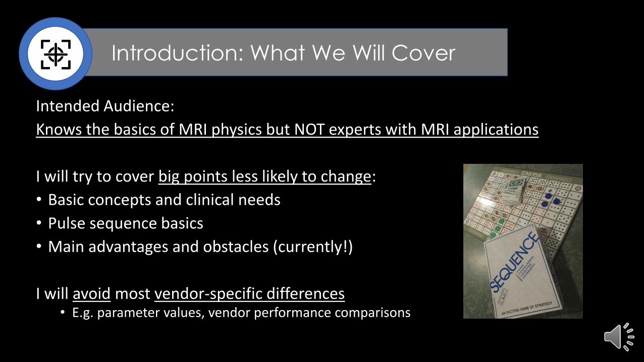
• Disadvantage: Can result in a blurring at the edges of tissues.
• Mitigation: reduce slice thickness, increase BW
1
2
3
1 23
High ΔB0
Low ΔB0
Slice selectio
n direction
In-plane direction
Frequency encoding direction
VIEW ANGLE

IQ Improvement #2: Metal Artifact Reduction
Slice Encoding for Metal Artifact Correction (SEMAC)
This 2D scan is repeated with different “SEMAC encodings”, making the pulse sequence look a bit like a 3D
This makes the scan potentially very long.

IQ Improvement #2: Metal Artifact ReductionMultiAcquisition Variable-Resonance Image Combination (MAVRIC)
MAVRIC performs a short 3D FSE, repeating it several times with a shifted transmit and receive frequency.
The idea is to use this to cover the entire range of frequencies.
Koch et.al., MRM;61:381 (2009)
Freq. 1Freq. 2
Freq. 3Freq. 4
Freq. 5Freq. 6
Freq. 7 Etc….
This makes the scan potentially very long.

Tips:
• MAVRIC and SEMAC are powerful methods for tough cases, but may not be needed for many implants
• For more practical scan durations:• Spatial resolution is reduced
• Recently, Compressed Sensing has been added
IQ Improvement #2: Metal Artifact Reduction

Tips:
• Small metal or titanium: VAT or just parameter optimization
• Big metal artifacts: VAT + (SEMAC or MAVRIC) + CS
• For Siemens use 30-40% VAT; for Philips it automatically picked
• Check EPIC to see if you know in advance the type of metal!• May help guide you in your choice of methods
IQ Improvement #2: Metal Artifact Reduction

Problem:
Shading artifacts primarily at 3T or higher , mainly in chest/abdomen
Classic example: ascites
IQ Improvement #3:
RF Shimming

Problem:
Wavelength cut to ~ 1/10 in water or soft tissue
IQ Improvement #3:
RF Shimming
Schick, F. Whole-body MRI at high field: technical limits and clinical potential. Eur Radiol 15, 946–959 (2005).

Problem:
This is commonly mislabeled as purely a “dielectric effect”
RF reflects in body creating “standing waves”(see blue wave below)
IQ Improvement #3:
RF Shimming
RF source

Solution:• “RF shimming” (AKA, “parallel transmission” or “parallel transmit”
• Change phase and amplitude of at least 2 RF transmissions
• Makes RF transmit field more uniform.
IQ Improvement #3:
RF Shimming
RF source
RF source
+ =
Analogous to noise cancelling headphones
http://mriquestions.com/uploads/3/4/5/7/34572113/mr_achieva_tx_whitepaper_multitransmit.pdf
IQ Improvement #3:
RF Shimming
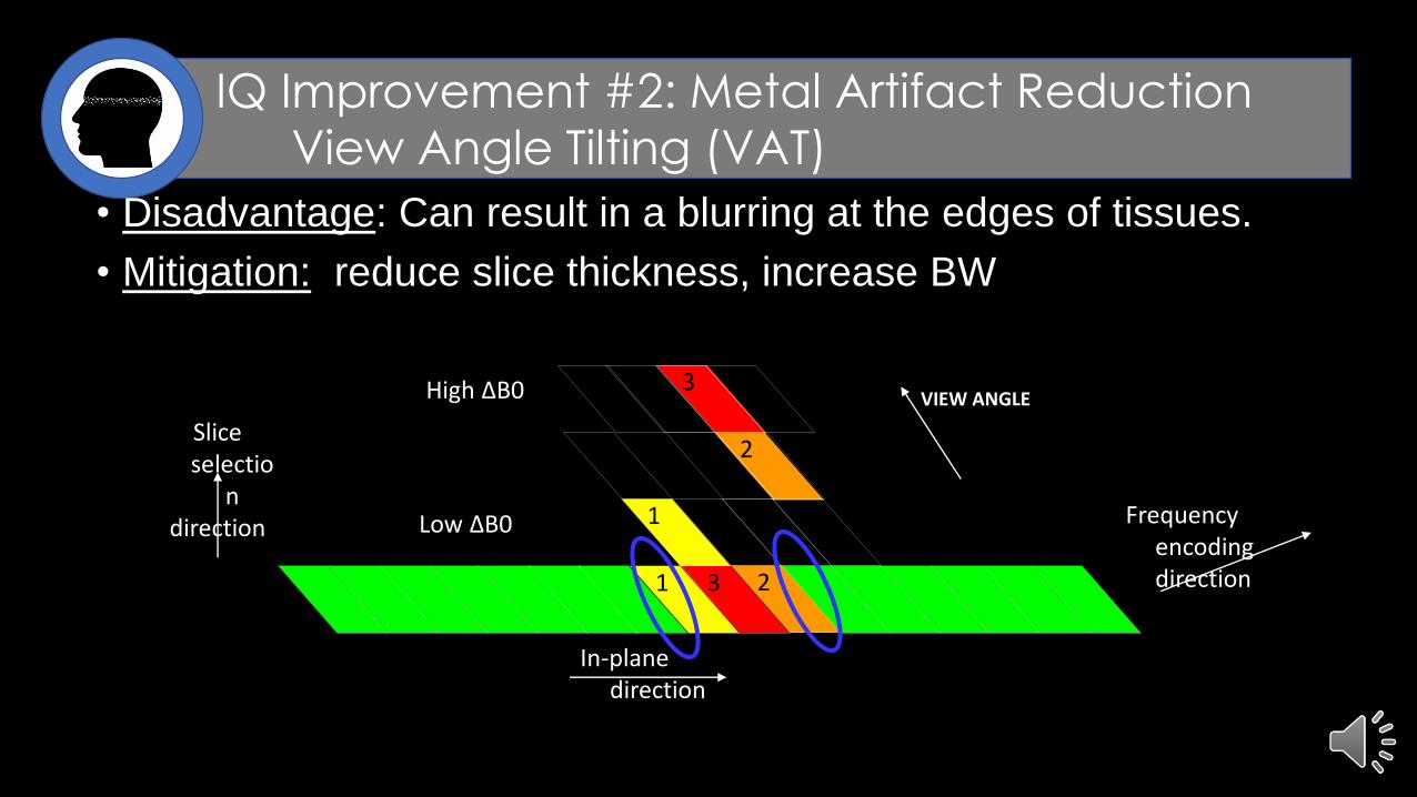
Andrews T, Ghostine J, Gonyea JV, Ebert GM, Braff SP, Filippi CG,
“Reduction in Dielectric Shading in Liver on Clinical 3T
Parallel Transmission MR System”, ISMRM Proc., 2010.
Single Transmit Parallel Transmit
Is this a window/level trick?
Corrected an 85% signal drop in left lobe of liver.

Tips:
No parameters to really tweak, BUT
- For 2 transmitters this reduces RF hot spots, reducing whole body average SAR
- This might allow for faster scanning (in RF Normal Mode)
- RF shimming is in x-y plane (i.e. axial plane), extending slightly z-direction- So may not help much with coronal or sagittal, esp. at edge of FOV
IQ Improvement #3:
RF Shimming

Fat suppression is critically valuable but historically difficult to achieve for many pathologies studied with clinical MR.
The Dixon Method has been recently made more robust with several new improvements (details vary by vendor approach):• good fast B0 mapping and corrections at edge of FOV
• better eddy current corrections
• multi-peak fat models (and greater TE selection flexibility)
• faster reconstruction, etc.
Artifacts far less common than in the past
IQ Improvement #4:
Dixon Fat Suppression

Dixon Method
Hydrogen spins in fat precess slower than those in water molecules.
IQ Improvement #4:
Dixon Fat Suppression
+
+TE=2.2ms
TE=4.4ms
=
=
Fat and waterIN PHASE
Fat and waterOPPOSED PHASE
Graph courtesy of Allen D. Elster, MRIquestions.com
At 1.5T:

Dixon Method
IQ Improvement #4:
Dixon Fat Suppression
+
TE=2.2msTE=4.4ms
+
++
-
+ =
=
2 x
2 x
WATERONLY
FATONLY

So you get 4 image sets:
- In-phase
- Opposed-phase
- Water only
- Fat only
2 for the price of 1 !
IQ Improvement #4:
Dixon Fat Suppression
Non-fat suppressed image
Fat suppressed image

Pulse sequences
• Gradient echo (usually w 2 or 3 echoes)• Usually w/ 2 or 3 echoes• Liver scans
• Fast spin echo • 2 acquisitions w/ different echo times, • Double scan duration• MSK scans
• Might help for T1W post Gd near metal
• “Fat water swap” artifacts can sometimes occur
IQ Improvement #4:
Dixon Fat Suppression
Glocker, et al “Correction of Fat-Water Swaps in Dixon MRI” MICCAI 2016

Tissues stiffness has long been assessed superficially by palpation.
By attaching an external pneumatic “driver” to a patient, phase mapping methods can be used to map elastic properties (esp. shear stiffness).
Quantitative Imaging #1:
MR Elastography25
9
Image: https://blog.cincinnatichildrens.org/cms/radiology/mri-elastography

Primary use: liver fibrosis assessment for chronic liver disease
Pulse sequence: Gradient echo, but increasingly EPI (for speed)
Troubleshooting tip: Check source images for signal dropout/poor mask
Quantitative Imaging #1:
MR Elastography25
9
Tan, et al “Magnetic Resonance Elastography and Other Magnetic Resonance Imaging Techniques in Chronic Liver Disease: Current Status and Future Directions” Gut and Liver, 2016

Clinical need:
• Diffuse myocardial fibrosis and global myocardial edema are an important part of a non-invasive diagnostic assessment of cardiac disease.
• Need to differentiate between myocardial infarction, focal scar, and fibrosis
• T1-weighted IR cardiac MR can miss diffuse myocardial fibrosis if myocardial signal is nulled (which looks like healthy tissue)
• Fast accurate mapping of T1 values would avoid this
Quantitative Imaging #2:
T1 Mapping25
9

Pulse sequence (Siemens and Philips)
MOdified Look-Locker Inversion recovery (MOLLI): IR pulse followed by multiple small FA excitations and measurements during inversion recovery w/ cardiac triggering modifications.
Quantitative Imaging #2:
T1 Mapping25
9
Pre-Contrast Enhancement (CE):“native T1”
Post-CE“enhanced T1”

Quantitative Imaging #2:
T1 Mapping25
9
• Post- used for late-Gd enhancement (LGE) assessment of non-enhancing scars
• Subtraction of pre- and post- w/ a hematocrit correction results in an estimated extracellular volume (ECV) map (probing the interstitium for edema, fibrosis, or amyloid).
Maestrini, et al “New Generation Cardiac Parametric Mapping: the Clinical Role of T1 and T2 Mapping”, FLASH Magnetom 2013

Quantitative Imaging #2:
T1 Mapping25
9
GE uses a series of saturation recovery scans w/ a balanced SSFP readout to try to avoid underestimates of T1 inherent to MOLLI.
• Trade names: • Siemens (MyoMaps)
• GE (SMART1 Map)
• Philips (CardiacQuant)

Non-Alcoholic Fatty Liver Disease (NAFLD)
↓
Non-Alcoholic SteatoHepatitis (NASH)
↓
Cirrhosis
NAFLD is most common chronic liver disease in the US
Liver fat content is an early marker of development of NASH and cirrhosis
Quantitative Imaging #3:
Fat Fraction/T2* Mapping25
9
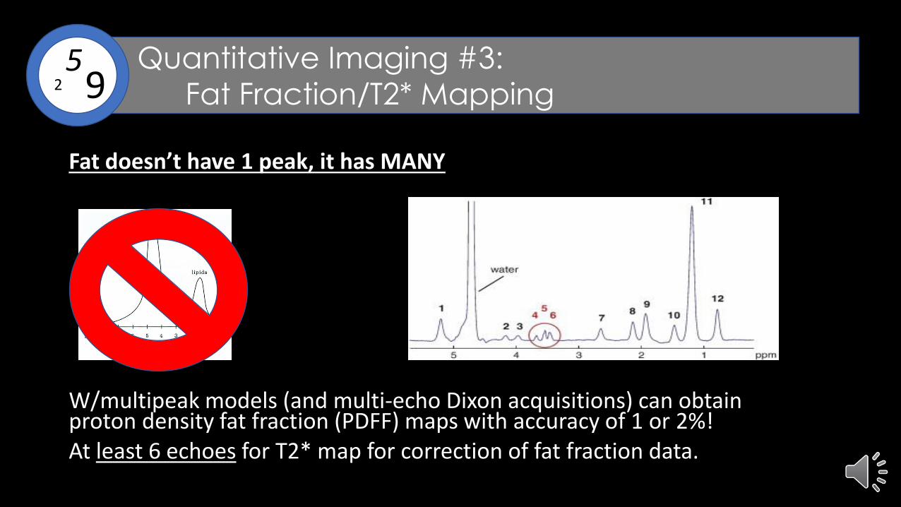
Fat doesn’t have 1 peak, it has MANY
W/multipeak models (and multi-echo Dixon acquisitions) can obtain proton density fat fraction (PDFF) maps with accuracy of 1 or 2%! At least 6 echoes for T2* map for correction of fat fraction data.
Quantitative Imaging #3:
Fat Fraction/T2* Mapping25
9

T2* maps can also be used to estimate iron content, critical to assessing hereditary HFE hemochromatosis, thalassemia, sickle cell anemia, aplastic anemia, and myelodysplasia.
Trade names: Siemens (MapIT), GE (Star-Map),
Philips (StarQuant/CardiacQuant), Hitachi (T2*RelaxMap)
For detailed parameter/processing: Henninger, et al “Practical guide to quantification of hepatic iron with MRI” Euro. Radiol. 2020.
Quantitative Imaging #3:
Fat Fraction/T2* Mapping25
9

Fat Fraction Mapping
Trade names:
Siemens (LiverLab),
GE (IDEAL IQ),
Philips (mDIXON Quant)
Quantitative Imaging #3:
Fat Fraction/T2* Mapping25
9
LiverLabScreen w/FF mapsAnd T2* maps

RSNA project to foster development and adoption of hardware and software standards for quantitative imaging
Scanning protocols are described in “profiles” for specific applications
MRI Profiles:
MR Dynamic Contrast Susceptibility (DSC)
MR Diffusion-Weighted Imaging (DWI)
MR Elastography of the Liver (MRE)
MR Dynamic Contrast Enhancement (DCE)/
MR DCE MRI Quantification
MR MSK cartilage for joint disease
25
Each of these needs advanced QC
Could this lead to more billable work?
25
9Quantitative Imaging:
Quantitative Imaging Biomarkers Alliance (QIBA)25
9

Thank You and Stay Safe!

Bonus Slides

Speed Improvement #1:
Simultaneous MultiSlice (SMS)
5min session vs. 10min session
Similar diagnostic performance