Embed Size (px)
Citation preview

State of New MexicoEnergy, Minerals and Natural Resources Department
Susana MartinezGovernor
David MartinCabinet Secretary
Brett F. Woods, Ph.D.Deputy Cabinet Secretary
David R. Catanach Division DirectorOil Conservation Division
New Mexico Oil Conservation Division approval and conditions listed below are made in accordance with OCD Rule 19.15.7.11 and are in addition
to the actions approved by BLM on the following 3160-3 APD form.
Operator Signature Date: IP- 3~ 1 ^
Well information; ^Operator loPK_________ Well Name and Number \a). LtjhfME- Ur\,\~ n
API# 3(Vfoc7S~ 35^3^ , Section , Township cP3> (n)s, Range 09 E(vj)
Conditions of Approval:(See the below checked and handwritten conditions)
^ Notify Aztec OCD 24hrs prior to casing & cement.
^ Hold C-104 for directional survey & “As Drilled” Plat ^ Hold C-104 fo^SsL NSP, DHC
o Spacing rule violation. Operator must follow up with change of status notification on other well
to be shut in or abandoned
o Regarding the use of a pit, closed loop system or below grade tank, the operator must comply with the following as applicable:
• A pit requires a complete C-144 be submitted and approved prior to the construction or
use of the pit, pursuant to 19.15.17.8.A
• A closed loop system requires notification prior to use, pursuant to 19.15.17.9.A
• A below grade tank requires a registration be filed prior to the construction or use of the
below grade tank, pursuant to 19.15.17.8.C
o Once the well is spud, to prevent ground water contamination through whole or partial conduits from the surface, the operator shall drill without interruption through the fresh water zone or zones and shall immediately set in cement the water protection string
Regarding Hydraulic Fracturing, review EPA Underground Injection Control Guidance 84
Oil base muds are not to be used until fresh water zones are cased and cemented providing isolation from the oil or diesel. This includes synthetic oils. Oil based mud, drilling fluids and solids must be contained in a steel closed loop system.
Well-bore communication is regulated under 19.15.29 NMAC. This requires well-bore Communication to be reported in accordance with 19.15.29.8.
________NMOCD Approved by Signature2-H-/C
Date
1220 South St. Francis Drive • Santa Fe, New Mexico 87505 Phone (505) 476-3460 • Fax (505) 476-3462 ■ www.emnrd.state.nm.us/ocd

RECFP-'*^
Form 3160-3(September2001) Q ( 20^
UNITED STATESDEPARTMENT OF THE INTERIORBUREAU OF LAND MANAGEMENT Farminotrv
APPLICATION FOR PERMIT TO DRILL Olf REENTER
FORM APPROVED0MB No. 1004-0136
Expires January 31,2004
5. Lease Serial No.
NO-G-1401-18676. If Indian, Allottee or Tribe Name
la. Type of Work: E3 DRILL □ REENTER
lb. Type of Well: 13 Oil Well □ Gas Well □ Other K1 Single Zone □ Multiple Zone
7. If Unit or CA Agreement, Name and No.
NMNM 135216X8. Lease Name and Well No.
W. Lybrook Unit #707H
2. Name of Operator
WPX Energy Production. LLC
9. API Well No.
ii0 -0*4ff 73 (
3a. Address
P.O. Box 640 Aztec, NM 87410
3b. Phone No. (include area code)
(505)333-l^Q8 ~n,..nmT
10. Field and Pool, or Exploratory
« Lybrook Mancos W.4. Location^ Well (Report location clearly and in accordance with any State requirement^ OUIMD. UIV UIOI*
At surfacft 877’ FSL & 366’ FEL SEC 12, 23N 9WAt proposed propone 330’ FNL & 2361’ FWL SEC 12,23N 9W FEB 15 2016
M1. Sec., T., R., M., or Blk. and Survey or Area
SHL: Sec 12, T23N, R9W
BHL: Sec 12, T23N, R9W
14. Distance in miles and direction from nearest town or post office*
From intersection US HWY 550 & US HWY 64 Bloomfield, NM South HWY 550 37.8 miles to MM 113.4
12. County or Parish 13. State
San Juan NM
15. Distance from proposed*
location to nearest property or lease line, ft.(Also to nearest drig. unit line, if any) 36g.
16. No. of Acres in lease
160 acres
17. Spacing Unit dedicated to this well239.81 acres
IA Bond No. on file
6
18. Distance from proposed location* to nearest well, drilling, completed, applied for, on this lease, ft.
20’
19. Proposed Depth
10189.42’MD / 4938’TVD
20. BLM/B
B00157
21. Elevations (Show whether DF, KDB, RT, GL, etc.)
6733’ GR
22. Approximate date work will start*
January 1,2015
23. Estimated duration
1 month
24. Attachments
The following, completed in accordance with the requirements of Onshore Oil and Gas Order No. 1, shall be attached to this form:
1. Well plat certified by a registered surveyor.
2. A Drilling Plan.
3. A Surface Use Plan (if the location is on National Forest System Lands, the
SUPO shall be filed with the appropriate Forest Service Office).
4. Bond to cover the operations unless covered by an existing bond on file (seeItem 20 above).
5. Operator certification.
6. Such other site specific information and/or plans as may be required by the authorized officer.
25. Signatuje 1
A M Jif)/] 1 Name (Printed/Typed)
X 1/ J 1 Marie E. Jaramillo
Date12/315Title U\J1
Permit Telhnic
[(Jan m \
Approved by (Signature) , /TV/ W/ / x Name (Printed/Typed) Date / /
X//2Aa/™e / ' / ^- - - ' Office —___ ^
______ fv-A__________________________________________________________
operations thereon.Conditions of approval, if any, are attached.
Title 18 U.S.C. Section 1001 and Title 43 U.S.C. Section 1212, make it a crime for any person knowingly and willfully to make to any department or agency of the United States any false, fictitious or fraudulent statements or representations as to any matter within its jurisdiction.
*(Iinstructions on reverse)
WPX Energy Production, LLC, proposes to develop the Lybrook Mancos W formation at the above described location in accordance with the attached drilling and surface
use plans.
The well pad surface is under jurisdiction of the BLM and FIMO and is on lease on IA lands and will be twinned with the W. Lybrook Unit #708H/709H/747H/748H/749H.
This location has been archaeologically surveyed by La Plata. Copies of their report have been submitted directly to the BLM, FIMO, BIA & NNHPD.
The new 1303’ on lease road on IA surface will be built and permitted via the APD.
A new 2761 ’ on lease pipeline of IA lands will be built and permitted via the APD, 1705.3 ’ will be on IA surface & 1056.1 ’ will be on BLM surface.
1 j^cil^e^ j^rjl^w^ll wifi b^lo^ted_on theRemote Facilities Pad 23-8-18D located on BLM surface and will be built & permitted ^ procedural
\CT10N DOES NOT RELIEVE THE LESSEE AND OPERATOR FROM OBTAINING ANY OTHER A/
AUTHORIZATION REQUIRED FOR OPERATIONS *..11 „ON FEDERAL AND INDIAN LANDS NMOCD
reviewpursuant to 43 CFR 3165.3 and appeal pursuant to 43 CFR 3165.4
DRILLING OPERATIONS AUTHORIZED ARE SUBJECTTO COMPLIANCE WITH ATTACHED'GENERAL REQUIREMENTS*

District I1625 N. French Drive. HoODs. NM B8240 Phone: (575) 393-6161 Fax: (575) 393-0720 District II811 S. First Street. Artesia. NM 88210 Phone: (575) 748-1283 Fax: (575) 748-9720District III1000 Rio Brazos Road. Aztec. NM 87410 Phone: (505) 334-6178 Fax: (505) 334-6170 District IV1220 S. St. Francis Drive. Scnta Fe. NM 87505 Phone: (505) 476-3460 Fax: (505) 476-3462
State of New MexicoEnergy. Minerals S Natural Resources Department
OIL CONSERVATION DIVISION
1220 South St. Francis Drive Santa Fe. NM 87505
Form C-102 Revised August 1. 2011
Submit one copy to Appropriate District Office
□ AMENDED REPORT
RECEIVED
WELL LOCATION AND ACREAGE DEDICATION PLAT DEC 0 / 2015'API Number ‘Pool Code
3^-645-3513^_________
----------------------------------------------------------------------------------- rPbb1 Name----------------------------------------------------------------------------------------
LYBROOK MANCOS Farmington F,elc Otrlrf>'Property Code "Property Name LJU,y°
W LYBROOK UNITuoruzmmgfiKiea*.
707H’OGfilD No.
120782"Operator Name
WPX ENERGY PRODUCTION. LLC"Elevation
6733
10 Surface LocationUL or lot no. Section Townafiip Range Lot Ion Feet from the North/South line Feet free the Eeet/Mcst line Qxnty
P 12 23N 9W 877 SOUTH 366 EAST SAN JUAN
11 Bottom Hole Location If Different From SurfaceUL or lot no.
cSection
12Tnranip
23NRange
gwLot Itr Feet from the
330itarth/South line
NORTHFeet from the
2361East/Nest line
WESTCounty
SAN JUAN° Dedicated
NW/4 SW/4 (Section 7) 239.81 NE/4 NW/4. NW/4 NE/4S/2 NE/4. NE/4 SE/4 (Section 12)
“joint or Infill “ Consolidation Code n Order No.
R-14051 - 12.807.24 Acres
NO ALLOWABLE WILL BE ASSIGNED TO THIS COMPLETION UNTIL ALL INTERESTS HAVE BEEN CONSOLIDATED OR A
NON-STANDARD UNIT HAS BEEN APPROVED BY THE DIVISION
END-OF-LATERAL 330- FNL 2361‘ FNL
SECTION 12. T23N. R9N LAT: 36.247908 V
LONG: 107.740734 V DATUM: NAD 1927
LAT: 36.247920 V LONG: 107.741347 V
DATUM NAD 1963
SURFACE LOCATION 677 FSL 366' FEL
SECTION 12. T23N R9N LAT: 36236624 'N
LONG: 107.732279 V DATUM NAD1927
LAT: 36236637 "N LONG: 107.732692 V
DATUM NAD 1983
(RECORD)NO V3 N 263668-
NO'0523V 263727- MEASURED)
POINT-OF-ENTRY 1666- FSL 463- FNL SECTION 7. T23N R8N
LAT: 36236652 V LONG: 107.729624 V
DATUM NAD 1927
LAT: 36238665 V LONG: 107.730237 V
DATUM NAD 1983
(RECORD)S88'i7V 2533.74
S88 ‘12 39 V 2533.67- 16 (MEASURED)
(RECORD)S88'17N 2533.74'
S88‘12 39V 253367'
(RECORD)NB7-59N 2861.76
N87‘58 25V 2861.91 (MEASURED)
(RECORD)S88‘58V 2628.12'
S88‘54D7V 2629.11-
&s.pivriW*F
(MEASURED)S89 21 25V 263424
S89 24V 2634.72- (RECORD)
(MEASURED)S89-48 14V 2635.04'
S89 51V 2635.38' (RECORD)
(MEASURED)NB9 -55 43V 2630.64
NB9-52V 2632.74- (RECORD)
(MEASURED)S89‘1640 V 263530-
S89 26V 2634.06- (RECORD)
(MEASURED)N04‘4503V 2767.12- N04’42V 276738-
(RECORD)
17 OPERATOR CERTIFICATIONI hereby certify that the information contained herein is true and complete to the best of my knowledge and belief, and that this organization either owns a working interest or unleased mineral Interest In the land Including the proposed bottom-hole location or has a right to drill this ijell at this location pursuant
ith an owner of such a mineral a voluntar^pooling
Ivision.
ill Address
“SURVEYOR CERTIFICATIONI hereby certify that the well location shown on this plat was plotted from field notes of actual surveys made by me or under my supervision and that the same is true and correct to the best of my belief.
Date Revised; NOVEMBER 12. 2015 Date of Survey: MAY 18. 2015
Signature and Seal of Professional Surveyor
Jason C. EdwardsCertificate Number 15269

I I
WPXENERGY
WPX Energy
Operations Plan
(Note: This procedure will be adjusted onsite based upon actual conditions)
Date:
Well Name:
SH Location:
BH Location:
December 7, 2015
W Lybrook Unit #707H
SESE Sec 12-23N-09W
NENWSec 12-23N-09W
Field:
Surface:
Elevation:
Minerals:
Lybrook Mancos W
IA
6733' GR
IA
Measured Depth: 10,189.42'
I. GEOLOGY: SURFACE FORMATION - NACIMIENTOA. FORMATION TOPS (KB)
NAME MD TVD NAME MD TVD
OJO ALAMO 673 673 POINT LOOKOUT 3,834 3,660
KIRTLAND 882 881 MANCOS 4,034 3,847
PICTURED CLIFFS 1,266 1,257 GALLUP 4,407 4,196
LEWIS 1,382 1,368 KICKOFF POINT 5,150.79 4,807.71
CHACRA 1,657 1,627 TOP TARGET 5,332 4,888
CLIFF HOUSE 2,808 2,702 LANDING POINT 5,542.07 4,923.00
MENEFEE 2,861 2,751 BASE TARGET 5,542.07 4,923.00
TD 10,189.42 4,938.00
B. MUD LOGGING PROGRAM: Mudlogger on location from surface csg to TD.
C. LOGGING PROGRAM: LWD GR from surface casing to TD.
D. NATURAL GAUGES: Gauge any noticeable increases in gas flow. Record all gauges in Tour book
and on morning reports.
II. DRILLING
A. MUD PROGRAM: LSND mud (WBM) will be used to drill the 12-1/4" Surface hole, the 8 3A" Directional Vertical hole, and the curve portion of the wellbore. A LSND (WBM) or (OBM) will be used to drill the lateral portion of well. Treat for lost circulation as necessary. Obtain 100% returns prior to cementing. Notify Engineering of any mud losses.
B. BOP TESTING: While drill pipe is in use, the pipe rams and the blind rams will be function tested once each trip. The anticipated reservoir is expected to be less than 1300 psi, so the BOPE will be tested to 250 psi (Low) for 5 minutes and 1500 psi (High) for 10 minutes. Pressure test surface casing to 600 psi for 30 minutes and intermediate casing to 1500 psi for 30 minutes. Utilize a BOPE Testing Unit with a recording chart and appropriate test plug for testing. The drum brakes will be inspected and tested each tour. All tests and inspections will be recorded in the tour book as to time and results.

III. MATERIALSA. CASING PROGRAM:
CASING TYPE OH SIZE (IN) DEPTH (MD) CSG SIZE WEIGHT GRADE CONN
SURFACE 12.25" 320.00' 9.625" 36 LBS J-55 or equiv STC
INTERMEDIATE 8.75" 5,542.07' 7" 23 LBS J-55 or equiv LTC
PRODUCTION 6.125" 5392.07' -10,189.42 4.5" 11.6 LBS P-110 or equiv LTC
TIE BACK 6.125" Surf. - 5392.07' 4.5" 11.6 LBS P-110 or equiv LTC
B. FLOAT EQUIPMENT:
1. SURFACE CASING: 9-5/8" notched regular pattern guide shoe. Run (1) standard centralizer on each of the bottom (4) joints of Surface Casing.
2. INTERMEDIATE CASING: 7" cement nose guide shoe with a self-fill insert float. Place float collar one joint above the shoe. Install (1) centralizer on each of the bottom (3) joints and one standard centralizer every (3) joints to 2,500 ft. Run (1) centralizer at 2,500 ft., 2,300ft., 2,000ft., 1,500 ft., and 1,000 ft. Place DV tool @ the top of the Chacra formation. If cement is circulated back to surface on the first stage, a cancelation device will be dropped to shift the dv tool closed and the 2nd stage cement job will be aborted at that time.
3. PRODUCTION LINER: Run 4-1/2” Liner with cement nose guide Float Shoe + Ijt.of 4- 1/2" casing + Landing Collar + 4-1/2” pup joint + 1 RSI (Sliding Sleeve) positioned inside the 330ft Hard line. Centralizer program will be determined by Wellbore condition and when Lateral is evaluated by Geoscientists and Reservoir Engineers. Set seals on Liner Hanger. Test TOL to 1500 psi for 15 minutes.
C. CEMENTING:
(Note: Volumes may be adjusted onsite due to actual conditions)
1. Surface 5 bbl Fresh Water Spacer, 100 sx (160 cu.ft.) of 14.5 ppg Type l-ll (Neat G) + 20% Fly Ash cement w/ 7.41 gal/sack mix water ratio @ 1.61 cu ft/sx yield. Calculated @ volume + 50% excess. WOC 12 hours. Test csg to 600psi. Total Volume: (160 cu-ft/100 sx/ Bbls).TOC at Surface.
2.lntermediate STAGE 1: Spacer #1: 20 bbl (112 cuft) Chemwash. Lead Cement: 106 bbls, 301 sks, (593 cuft), 12.3 ppg @ 1.97 cuft/sk yield. Tail Cement: 91 bbls, 391 sks, (509 cuft), 13.5 ppg @ 1.3 cuft/sk yield. Displacement: Displace w/ +/- 218 bbl Drilling mud or water.Total Cement: 196 bbls, 692 sks, (1102 cuft)STAGE 2: Spacer #1: 20 bbl (112 cuft) Chemwash. Lead Cement: 34 bbls, 98 sks, (191 cuft), 12.3 ppg @ 1.97 cuft/sk yield. Tail Cement: 16 bbls, 78 sks, (90 cuft), 13.5 ppg @1.3 cuft/sk yield. Displacement: Displace w/ +/- 61 bbl Drilling mud or water.Total Cement: 50 bbls, 176 sks, (281 cuft)
3. PROD. LINER: Spacer #1:10 bbl (56.cu-ft) Water Spacer. Spacer #2: 40 bbl 9.5 ppg (224.6 cu-ft) Tuned
Spacer III. Spacer #3:10 bbl Water Spacer. Lead Cement: Extencem ™ System. Yield 1.36
cuft/sk 13.3 ppg (470 sx /639 cuft /114 bbls). Tail Spacer: 20 BBL of MMCR. Displacement:
Displace w/ +/-140 bbl Fr Water. Total Cement (470 sx /639bbls).

COMPLETION
A. CBL
I.
Run CCL for perforating
A. PRESSURE TEST
1. Pressure test 4-1/2" casing to 4500 psi max, hold at 1500 psi for 30 minutes.Increase pressure to Open RSI sleeves.
B. STIMULATION
1. Stimulate with approximately 2,805,000# 20/40 mesh sand and 340,000# 16/30 mesh sand in 619,113 gallons water with 42,696 mscf N2 for 17 stages.
2. Isolate stages with flow through frac plug.
3. Drill out frac plugs and flowback lateral.
C. RUNNING TUBING1. Production Tubing: Run 2-7/8", 6.5#, J-55, EUE tubing with a SN on top of bottom joint. Land tubing near Top of Liner.
• Although this horizontal well will be drilled past the applicable setbacks, an unorthodox location application is not required because the completed interval in this well, as defined by 19.15.16.7 B(1) NMAC.will be entirely within the applicable setbacks . This approach complies with all applicable rules, including 19.15.16.14 A(3) NMAC, 19.15.16.14 B(2) NMAC, 19.15.16.15 B(2)NMAC, and 19.15.16.15. B(4) NMAC.
NOTE:
Proposed Operations:
A 4-1/2” 11.6# P-110 Liner will be run to TD and landed +/-150 ft. into the 7” 23# J-55 Intermediate casing with a Liner Hanger and pack-off assembly then cemented to top of liner hanger.
After cementing and TOL clean up operations are complete, the TOL will be tested to 1500 psi (per BLM).

s s
WPX EnergyT23N R9W
Lybrook 2309-12D Lybrook UT #707H - Slot A6
Wellbore #1
Plan: Design #1 2Nov15 sam
Standard Planning Report
02 November, 2015

WPXPlanning Report
Database: COMPASS Local Co-ordinate Reference: Well W Lybrook UT #707H (A6) - Slot A6
Company: WPX Energy TVD Reference: KB @ 6747.00usft (Aztec 920)
Project: T23N R9W MD Reference: KB @ 6747.00usft (Aztec 920)
Site: W Lybrook 2309-12D North Reference: True
Well: W Lybrook UT #707H Survey Calculation Method: Minimum Curvature
Wellbore: Wellbore #1
Design: Design #1 2Nov15 sam
Project T23N R9W
Map System: US State Plane 1927 (Exact solution) System Datum: Mean Sea Level
Geo Datum: NAD 1927 (NADCON CONUS)
Map Zone: New Mexico West 3003
Site W Lybrook 2309-12D
Site Position:
From:
Position Uncertainty:
Map
0.00 usft
Northing:
Easting:
Slot Radius:
1,905,338.99 usft
529,692.39 usft
13.200 in
Latitude:
Longitude:
Grid Convergence:
36.236489
-107.732650
0.06 °
Weil W Lybrook UT #707H - Slot A6
Well Position +N/-S 49.30 usft Northing: 1,905,388.40 usft Latitude: 36.236624
+E/-W 109.42 usft Easting: 529,801.76 usft Longitude: -107.732279
Position Uncertainty 0.00 usft Wellhead Elevation: 0.00 usft Ground Level: 6,733.00 usft
Wellbore Wellbore #1
Magnetics Model Name Sample Date Declination
nDip Angie
nField Strength
(nT)
IGRF200510 12/31/2009 9.98 63.08 50,621
Design Design #1 2Nov15 sam
Audit Notes:
Version: Phase: PLAN Tie On Depth: 0.00
Vertical Section Depth From (TVD) ♦N/-S ♦E/-W Direction
(usft) (usft) (usft) (bearing)
0.00 0.00 0.00 328.74
Plan Sections
Measured Vertical Dogleg Build Turn
Depth Inclination Azimuth Depth +N/-S +E/-W Rate Rate Rate TFO(usft) n (bearing) (usft) (usft) (usft) (°/100usft) (°/100usft) (7100usft) (") Target
0.00 0.00 0.00 0.00 0.00 0.00 0.00 0.00 0.00 0.00
500.00 0.00 0.00 500.00 0.00 0.00 0.00 0.00 0.00 0.00
1,545.77 20.92 78.86 1,522.70 36.46 185.21 2.00 2.00 0.00 78.86
4,341.82 20.92 78.86 4,134.51 229.27 1,164.57 0.00 0.00 0.00 0.00
5,150.79 60.00 315.18 4,807.71 549.99 1,042.42 9.00 4.83 -15.29 -131.03 Start 60 tan #707H
5,210.79 60.00 315.18 4,837.71 586.85 1,005.79 0.00 0.00 0.00 0.00 End 60 tan #707H
5,373.35 74.63 315.18 4,900.23 692.94 900.35 9.00 9.00 0.00 0.00
5,542.07 89.82 315.18 4,923.00 811.16 782.86 9.00 9.00 0.00 0.00 POE #707H
10,189.42 89.82 315.18 4,938.00 4,107.49 -2,493.10 0.00 0.00 0.00 0.00 BHL#707H
11/2X015 10:54:00AM Page 2 COMPASS 5000.1 Build 78

WPXPlanning Report
Database:Company:
Project:
Site:
Well:
Wellbore:
Design:
COMPASS
WPX Energy
T23N R9W
W Lybrook 2309-12D
W Lybrook UT #707H
Wellbore #1
Design #1 2Nov15 sam
Local Co-ordinate Reference:
7VD Reference:
MD Reference:
North Reference:
Survey Calculation Method:
Well W Lybrook UT #707H (A6)
KB @ 6747.00usft (Aztec 920)
KB @ 6747.00usft (Aztec 920)
True
Minimum Curvature
- SlotA6
Planned Survey
Measured
Depth
(us ft)Inclination
nAzimuth
(bearing)
Vertical
Depth
(usft)+N/-S
(usft)
+E/-W
(usft)
Vertical
Section
(usft)
Dogleg
Rate
(*/100usft)
Build Tum
Rate Rate
(°/100usft) (°/100usft)
0.00 0.00 0.00 0.00 0.00 0.00 0.00 0.00 0.00 0.00
320.00 0.00 0.00 320.00 0.00 0.00 0.00 0.00 0.00 0.00
9 5/8"
500.00 0.00 0.00 500.00 0.00 0.00 0.00 0.00 0.00 0.00
Start Build 2.00
1,000.00 10.00 78.86 997.47 8.41 42.70 -14.97 2.00 2.00 0.00
1,500.00 20.00 78.86 1,479.82 33.37 169.51 -59.43 2.00 2.00 0.00
1,545.77 20.92 78.86 1,522.70 36.46 185.21 -64.93 2.00 2.00 0.00
Hold 20.92 Inclination
2,000.00 20.92 78.86 1,947.00 67.79 344.31 -120.70 0.00 0.00 0.00
2,500.00 20.92 78.86 2,414.05 102.26 519.44 -182.10 0.00 0.00 0.00
3,000.00 20.92 78.86 2,881.11 136.74 694.58 -243.50 0.00 0.00 0.00
3,500.00 20.92 78.86 3,348.16 171.22 869.71 -304.89 0.00 0.00 0.00
4,000.00 20.92 78.86 3,815.22 205.70 1,044.84 -366.29 0.00 0.00 0.00
4,341.82 20.92 78.86 4,134.51 229.27 1,164.57 -408.26 0.00 0.00 0.00
Start Build DLS 9.00 TFO -131.03
4,500.00 15.62 35.32 4,285.34 252.22 1,204.79 -409.51 9.00 -3.35 -27.52
5,000.00 47.22 320.88 4,718.39 460.32 1,123.74 -189.56 9.00 6.32 -14.89
5,150.79 60.00 315.18 4,807.71 549.99 1,042.42 -70.71 9.00 8.48 -3.78
Hold 60.00 Inclination
5,210.79 60.00 315.18 4,837.71 586.85 1,005.79 -20.20 0.00 0.00 0.00
Start Build DLS 9.00 TFO 0.005,373.35 74.63 315.18 4,900.23 692.94 900.35 125.20 9.00 9.00 0.00
Start DLS 9.00 TFO 0.00
5,500.00 86.03 315.18 4,921.47 781.35 812.49 246.37 9.00 9.00 0.00
5,542.00 89.81 315.18 4,923.00 811.11 782.91 287.16 9.00 9.00 0.00
r5,542.07 89.82 315.18 4,923.00 811.16 782.86 287.23 9.00 9.00 0.00
POE at 89.82 Inc 315.18 deg
6,000.00 89.82 315.18 4,924.48 1,135.97 460.06 732.38 0.00 0.00 0.00
6,500.00 89.82 315.18 4,926.09 1,490.62 107.60 1,218.43 0.00 0.00 0.00
7,000.00 89.82 315.18 4,927.71 1,845.26 -244.85 1,704.48 0.00 0.00 0.00
7,500.00 89.82 315.18 4,929.32 2,199.91 -597.30 2,190.52 0.00 0.00 0.00
8,000.00 89.82 315.18 4,930.93 2,554.55 -949.76 2,676.57 0.00 0.00 0.00
8,500.00 89.82 315.18 4,932.55 2,909.20 -1,302.21 3,162.62 0.00 0.00 0.00
9,000.00 89.82 315.18 4,934.16 3,263.84 -1,654.67 3,648.67 0.00 0.00 0.00
9,500.00 89.82 315.18 4,935.77 3,618.49 -2,007.12 4,134.71 0.00 0.00 0.00
10,000.00 89.82 315.18 4,937.39 3,973.14 -2,359.57 4,620.76 0.00 0.00 0.00
10,189.42 89.82 315.18 4,938.00 4,107.49 -2,493.10 4,804.90 0.00 0.00 0.00
TD at 10189.42
11/2/2015 10:54:00AM Page 3 COMPASS 5000.1 Build 78

WPXPlanning Report
Database: COMPASS Local Co-ordinate Reference: Well W Lybrook UT #707H (A6) - Slot A6
Company: WPX Energy TVD Reference: KB @ 6747.00usft (Aztec 920)
Project: T23N R9W MD Reference: KB @ 6747.00usft (Aztec 920)
Site: W Lybrook 2309-12D North Reference: True
Well: W Lybrook UT #707H Survey Calculation Method: Minimum Curvature
Wellbore: Wellbore #1
Design: Design #1 2Nov15sam
Design Targets
Target Name
- hit/miss target Dip Angle Dip Dir. TVD +N/-S +E/-W Northing Easting
-Shape n (bearing (usft) (usft) (usft) (usft) <usft) Latitude Longitude
Start 60 tan #707H 0.00 0.00 4,807.71 549.99 1,042.42 1,905,939.48 530,843.61 36.238135 -107.728744
- plan hits target center
- Point
End 60 tan #707H 0.00 0.00 4,837.71 586.85 1,005.79 1,905,976.30 530,806.94 36.238236 -107.728869
- plan hits target center
- Point
POE #707H 0.00 0.00 4,923.00 811.16 782.86 1,906,200.38 530,583.77 36.238852 -107.729625
- plan hits target center- Point
BHL #707H 0.00 0.00 4,938.00 4,107.49 -2,493.10 1,909,493.29 527,304.38 36.247908 -107.740734
- plan hits target center
- Point
Casing Points
Measured Vertical Casing Hole
Depth
(usft)
Depth
(usft) Name
Diameter
(In)
Diameter
(in)
320.00 320.00 9 5/8" 9.625 12.250
5,542.00 4,923.00 7" 7.000 8.750
Plan Annotations
Measured Vertical Local Coordinates
Depth Depth +N/-S +E/-W(usft) (usft) (usft) (usft) Comment
500.00 500.00 0.00 0.00 Start Build 2.00
1,545.77 1,522.70 36.46 185.21 Hold 20.92 Inclination
4,341.82 4,134.51 229.27 1,164.57 Start Build DLS 9.00 TFO -131.03
5,150.79 4,807.71 549.99 1,042.42 Hold 60.00 Inclination
5,210.79 4,837.71 586.85 1,005.79 Start Build DLS 9.00 TFO 0.00
5,373.35 4,900.23 692.94 900.35 Start DLS 9.00 TFO 0.00
5,542.07 4,923.00 811.16 782.86 POE at 89.82 Inc 315.18 deg
10,189.42 4,938.00 4,107.49 -2,493.10 TD at 10189.42
11/2/2015 10:54:00AM Page 4 COMPASS 5000.1 Build 78

WPXENERGY.Well Name: W Lybrook UT #707H
Surface Location: W Lybrook 2309-12DNAD 1927 (NADCON CONUS) , US State Plane 1927 (Exact solution) New Mexico West 3003
+N/-S +E/-W Northing Easting Latittude Longitude Slot0.00 0.00 1905388.40 529801.76 36.236624 -107.732279 A6
KB @ 6747.00usft (Aztec 920)
M Azimuths to True North /|\ Magnetic North: 9.98"
Magnetic Field Strength: 50621.1snT
Dip Angle: 63.08 Date: 12/31/2009
Model: IGRF200510
Surface Use Plan of Operations
7.0 Methods for Handling Waste
B.
C.
D.
E.
F.
G.
Cuttings
1. Drilling operations will utilize a closed-loop system. Drilling of the horizontal laterals will be accomplished with water-based mud. All cuttings will be placed in roll-off bins and hauled to a commercial disposal facility or land farm. WPX will follow Onshore Oil and Gas Order No. 1 regarding the placement, operation, and removal of closed-loop systems. No blow pit will be used.
2. Closed-loop tanks will be adequately sized for containment of all fluids.Drilling Fluids
1. Drilling fluids will be stored onsite in above-ground storage tanks. Upon termination of drilling operations, the drilling fluids will be recycled and transferred to other permitted closed-loop systems or returned to the vendor for reuse, as practical. All residual fluids will be hauled to a commercial disposal facility.
Spills1. Any spills of non-freshwater fluids will be immediately cleaned up and removed to an
approved disposal site.Sewage
1. Portable toilets will be provided and maintained during construction, as needed (see Figures 4a and 4b in Appendix B for the location of toilets).
Garbage and other water material1. All garbage and trash will be placed in a metal trash basket. The trash and garbage will
be hauled offsite and dumped in an approved landfill, as needed.Hazardous Waste
1. No chemicals subject to reporting under Superfund Amendments and Reauthorization Act Title III in an amount equal to or greater than 10,000 pounds will be used, produced, stored, transported, or disposed of annually in association with the drilling, testing, or completing of these wells.
2. No extremely hazardous substances, as defined in 40 CFR 355, in threshold planning quantities will be used, produced, stored, transported, or disposed of annually in association with the drilling, testing, or completing of these wells.
3. All fluids (i.e., scrubber cleaners) used during washing of production equipment will be properly disposed of to avoid ground contamination or hazard to livestock or wildlife.
Produced Water:1. WPX Energy will dispose of produced water from this well at one of the following
facilities:
a. Lybrook Yard WDW #1, API #30-039-27533, NMOCD permit #SWD-907, operated by Elm Ridge Resources, located in NE %, Section 14, Township 23 North, Range 7 West
b. Jillson Federal #1, NMOCD order #R-10168, operated by ConocoPhillips, located in NW %, Section 8, Township 24 North, Range 3 West
c. Basin Disposal, permit #NM-01-005, located in the NW 'A, Section 3, Township 29 North, Range 11 West
d. Sunco SWD #001, API #30-045-28653, NMOCD permit SWD-457, operated by Key Energy, located in NW 'A, Section 2, Township 29 North, Range 12 West
West Lybrook Unit #705H. #706H, #745H. & #746H West Lybrook Unit #707H, #708H, #709H, #747H. #748H, & #749H
Remote Facilities Pad 23-8-18D November 2015
-8-

Directions from the Intersection of US Hwy 550 & US Hwy 64
in Bloomfield, NM to WPX Energy Production, LLC Remote Facilities Pad 23-8-18D
451’ FNL & 896’ FWL, Section 18, T23N, R8W, N.MJP.M., San Juan County, NM
Latitude: 36.232985°N Longitude: 107.728379°W Datum: NAD1983
From the intersection of US Hwy 550 & US Hwy 64 in Bloomfield, NM, travel Southerly on US Hwy 550 for 37.8 miles to Mile Marker 113.4;
Go Right (South-westerly) on County Road #7890 for 0.8 miles to new access on left-hand side of existing roadway which continues for 110.8' to staked WPX Remote Facilities Pad 23-8-18D location.

Directions from the Intersection of US Hwv 550 & US Hwv 64
in Bloomfield. NM to WPX Energy Production, LLC W Lvbrook Unit #707H
877* FSL & 366* FEL. Section 12, T23N. R9W. N.M.P.M., San Juan County, NM
Latitude: 36.236637°N Longitude: 107.732892°W Datum: NAD1983
From the intersection of US Hwy 550 & US Hwy 64 in Bloomfield, NM, travel Southerly on US
Hwy 550 for 37.8 miles to Mile Marker 113.4;
Go Right (South-westerly) on County Road #7890 for 0.8 miles to fork in roadway;
Go Right (South-westerly) exiting County Road #7890 which is straight for 0.2 miles to new
access on right-hand side of existing roadway which continues for 1302.6* to staked WPX W
Lybrook Unit #707H location. •
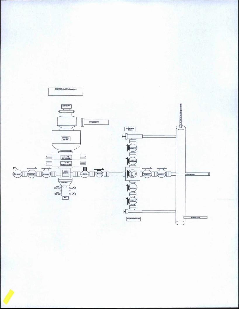
3,000 PSI rated Choke system