Embed Size (px)
Citation preview
.STATE OF CALIFORNIA-BUSINESS, TRANSPORTATION AND HOUSING AGENCY GRAY DAVIS, Governor
DEPARTMENT OF TRANSPORTATION ESC/OE MS #43 1737 30TH. Street 2ND. Floor SACRAMENTO, CA 945816
July 19, 1999
04-SF-80-5.5/7.8 04-0435U4
Addendum No. 2
Dear Contractor:
This addendum is being issued to the contract for construction on State highway in THE CITY AND COUNTY OF SAN FRANCISCO AT SAN FRANCISCO-OAKLAND BAY BRIDGE FROM 0.2 MILE WEST OF SAN FRANCISCO ANCHORAGE TO EAST END OF YERBA BUENA TUNNEL.
Submit bids for this work with the understanding and full consideration of this addendum. The revisions declared in this addendum are an essential part of the contract.
Bids for this work will be opened on August 24, 1999, instead of the original date of August 10, 1999.
This addendum is being issued to revise the Project Plans, the Notice to Contractors and Special Provisions, and the Proposal and Contract.
Project Plan Sheets 37, 58, 102, 120, 126, 127, 135, 203, 204, 206, 247, 248, 284, 294, 295, 296, 297, 298, 299, 300, 301, 303, 304, 324, 326, 357, 372, 376, 377, 648, 649, 687, 688, 753, 769, 803, 805, 808, 809, 810, 811, 812, 814, 815, 816, 819, 821, 825, 843, 845, 847, 848, 925, 926, 930, 931, 932, 934 950, 957, 960, 973, 974, 975, 976, 977, 979, 982, 986, 987 and 981 are revised. Half-sized copies of the revised sheets are attached for substitution for the like-numbered sheets.
Project Plan Sheets 100A, 100B, 100C, 100D, 100E and 100F are added. Half-sized copies of the added sheets are attached for addition to the project plans.
In the Special Provisions, Section 5-1.00, "Plans and Working Drawings," the first paragraph is revised as follows:
"When the specifications require working drawings to be submitted to the Engineer, the drawings shall be submitted to: Office of Resident Engineer, P.O. Box 191120, San Francisco, CA 94105-1120 (280 Beale Street, San Francisco, CC 94105)."
In the Special Provisions, Section 5-1.40, "Contaminated and Hazardous Material, General," is added as attached.
In the Special Provisions, Section 8-3.02, "Welding Quality Control," the fourth paragraph is revised as follows:
"Welding quality control shall apply when any work is welded in conformance with the provisions in Section 52, "Reinforcement," or Section 55, "Steel Structures," of the Standard Specifications."
In the Special Provisions, Section 8-3.02, "Welding Quality Control," the eighth paragraph is revised as follows:
"Except for welding that is performed at a permanent fabrication facility which is certified under the AISC Quality Certification Program, Category Cbr, Major Steel Bridges, welding inspection personnel or nondestructive testing (NDT) firms to be used in the work shall not be employed or compensated by any subcontractor, or by other persons or entities hired by subcontractors, who will provide other services or materials for the project. For welding performed at such facilities, the inspection personnel or NDT firms may be employed or compensated by the fabrication facility performing the welding."
Addendum No. 2 04-SF-80-5.5/7.8 Page 2 04-0435U4 July 19, 1999
In the Special Provisions, Section 8-3.02, "Welding Quality Control," the first subparagraph of the twenty-first paragraph is revised as follows:
"Personnel performing NDT shall be qualified in conformance with the requirements in the current edition of the American Society for Nondestructive Testing (ASNT) Recommended Practice No. SNT-TC-1A and the Written Practice of the NDT firm. The Written Practice of the NDT firm shall meet or exceed the requirements of the current edition of the ANST Recommended Practice No. SNT-TC-1A. Only individuals who are 1) qualified for NDT Level II, or 2) Level III technicians who have been directly certified by the ASNT and are authorized to perform the work of Level II technicians, shall perform NDT, review the results, and prepare the written reports."
In the Special Provisions, Section 8-3.02, "Welding Quality Control," the thirtysecond paragraph is revised as follows:
"All required repair work to correct welding deficiencies, whether discovered by the required visual inspection or NDT, or by additional NDT directed or performed by the Engineer, and any associated delays or expenses caused to the Contractor by performing these repairs, shall be at the Contractor’s expense."
In the Special Provisions, Section 10-1.07, "Obstructions," is revised as attached.
In the Special Provisions, Section 10-1.22A, "Jack Bridge," the following paragraph is added after the first paragraph:
"The structure shall be supported at two locations: Jack Bridge (Location A) at the San Francisco anchorage, and Jack Bridge (Location B) at Pier W1."
In the Special Provisions, Section 10-1.22E, "Modify Water and Air Lines (Bridge)," the second paragraph is revised as follows:
"Working drawings.--The Contractor shall submit complete working drawings to the Engineer in accordance with the provisions in Section 5-1.02, "Plans and Working Drawings," of the Standard Specifications."
In the Special Provisions, Section 10-1.22F, "Temporary Deck Bridging," is added as attached.
In the Special Provisions, Section 10-1.26, "PTFE Spherical Bearing," the following paragraph is added after the twenty-eighth paragraph:
"Finish coats will not be required on the bearings."
In the Special Provisions, Section 10-1.32, "Reinforcement," the seventh paragraph is revised as follows:
"The sixth paragraph of Section 52-1.08, “Splicing,” of the Standard Specifications is amended to read:
Except when otherwise specified, mechanical lap splicing shall conform to the details shown on the plans, the requirements for mechanical butt splices as specified in this Section 52-1.08, and Sections 52-1.08C, “Mechanical Butt Splices,” 52-1.08D, “Qualification of Welding and Mechanical Splicing,” and 52-1.08E, “Job Control Tests,” and the following:
The mechanical lap splice shall be a unit consisting of a sleeve, in which the reinforcing bars are positioned, and a wedge driven through holes in the sleeve and between the reinforcing bars. The mechanical lap splice shall only be used for splicing non-epoxy-coated deformed reinforcing bars Nos. 4, 5 and 6."

Addendum No. 2 04-SF-80-5.5/7.8 Page 3 04-0435U4 July 19, 1999
In the Special Provisions, Section 10-1.32, "Reinforcement," under title "52-1.08F Nondestructive Splice Tests," the thirteenth subparagraph of the tenth paragraph is revised as follows:
"Radiographic film shall be developed within a time range of one minute less to one minute more than the film manufacturer’s recommended maximum development time. Sight development will not be allowed."
In the Special Provisions, Section 10-1.34, "Steel Structures," is revised as attached.
In the Special Provisions, Section 10-1.39, "Clean and Paint Structural Steel," subsection "Cleaning," the third paragraph is revised as follows:
"The areas of existing steel to be dry spot blast cleaned shall consist of, as a minimum: (1) contact surfaces of structural steel connections, (2) member surfaces under bolt heads, nuts or washers of all new high-strength bolted connections (3) exposed bare surfaces of existing steel remaining after trimming, cutting, drilling or reaming, (4) all areas of existing steel within a 4-inch radius measured in any direction from the of point of application of heat for welding or flame cutting and (5) all areas within a 4 inch by 4 inch square centered on rivet or bolt to be removed."
In the Special Provisions, Section 10-1.39, "Clean and Paint Structural Steel," subsection "Cleaning," the seventh paragraph is revised as follows:
"Mineral and slag abrasives used for blast cleaning existing steel shall conform to the requirements in Abrasive Specification No. 1, "Mineral and Slag Abrasives," of the Steel Structures Painting Council and shall not contain hazardous material. Mineral and slag abrasives shall comply with the requirements for Class A, Grade 2 to 3 as defined therein."
In the Special Provisions, Section 10-1.39, "Clean and Paint Structural Steel," subsection "Measurement and Payment," the third paragraph is revised as follows:
"The contract lump sum price paid for clean and paint structural steel shall include full compensation for furnishing all labor, materials, tools, equipment, and incidentals, and for doing all the work involved in cleaning and painting the surfaces of the new structural steel, galvanized surfaces and finish coats on undercoated areas of existing metal, complete in place, including water rinsing, as shown on the plans, as specified in the Standard Specifications and these special provisions, and as directed by the Engineer."
In the Special Provisions, Section 10-3.01, "Description," in the second paragraph the eleventh item is revised as follows:
"11. Upper deck lighting standard and electrolier"
In the Special Provisions, Section 10-3.11, "Foundation Bolts," is revised as follows:
"10-3.11 LUMINAIRE FOUNDATION AND PEDESTAL Luminaire foundation and pedestal that are removed shall be installed
in the locations shown on the plans. All plates, bolts, and luminaire foundation steel shall conform to Section 55, "Steel Structures," of the Standard Specifications."
In the Special Provisions, Section 10-3.19, "15 kV Cable, 15 kV Slice Box, Cable Tray and Supports," the section title is revised as follows:
"Section 10-3.19 15kV Cable, Load and Relay Coordination Studies, 15 kV Splice Box, Cable Tray and Supports"
In the Special Provisions, Section 10-3.19, "15 kV Cable, 15 kV Slice Box, Cable Tray and Supports," the subsection "Load and Relay Coordination Studies," is added as attached.
Addendum No. 2 04-SF-80-5.5/7.8 Page 4 04-0435U4 July 19, 1999
In the Proposal and Contract, the Engineer’s Estimate Item 73 is revised and Items 74, 75 and 76 are added as attached.
To Proposal and Contract book holders:
• REPLACE PAGE 6 OF THE ENGINEER'S ESTIMATE IN THE PROPOSAL WITH THE ATTACHED REVISED PAGE 6 OF THE ENGINEER'S ESTIMATE. THE REVISED ENGINEER'S ESTIMATE IS TO BE USED IN THE BID.
• INDICATE RECEIPT OF THIS ADDENDUM BY FILLING IN THE NUMBER OF THIS ADDENDUM IN THE SPACE PROVIDED ON THE SIGNATURE PAGE OF THE PROPOSAL.
• Submit bids in the Proposal and Contract book you now possess. Holders who have already mailed their book will be contacted to arrange for the return of their book.
• Inform subcontractors and suppliers as necessary.
This office is sending this addendum by UPS overnight mail to Proposal and Contract book holders to ensure that each receives it.
If you are not a Proposal and Contract book holder, but request a book to bid on this project, you must comply with the requirements of this letter before submitting your bid.
Sincerely,
ORIGINAL SIGNED BY
NICK YAMBAO, Chief Plans, Specifications & Estimates Branch Office of Office Engineer
Attachments
5-1.40 CONTAMINATED AND HAZARDOUS MATERIAL, GENERAL Materials within the project limits contain inorganic and organic contaminants,
including lead and petroleum hydrocarbons. The concentrations of these contaminants may exceed local, state, or federal regulatory limits for unrestricted land disposal and may expose workers to potential health hazards.
The Contractor shall collect and analyze samples of the materials before beginning any earthwork for the various items of work. The samples shall be collected from within the excavation limits. The minimum number of samples analyzed to determine disposal characteristics shall be one sample per 225 square feet of excavation area. The samples shall be analyzed for metals, petroleum hydrocarbons, volatile organic compounds, semivolatile organic compounds, pesticides, and polychlorinated biphenyls in accordance with the methods specified in “Test Methods for Evaluating Solid Waste, Physical/Chemical Methods,” SW-846 published by the United States Environmental Protection Agency.
The Contractor shall submit a sampling and analysis plan to the Engineer for review 10 days prior to beginning excavation. Copies of analysis results shall be submitted to the Engineer prior to disposal of any material.
Transportation and disposal of regulated material, as determined by test results, will be paid for as extra work as provided in Section 4-103D of the Standard Specifications.
Full compensation for preparing a sampling and analysis plan, collecting samples, and analyzing samples shall be considered as included in the prices paid for the various items of work involved and no additional compensation shall be allowed therefor.
CONTRACT NO. 04-0435U4 ADDED PER ADDENDUM NO. 2 DATED JULY 19, 1999

10-1.07 OBSTRUCTIONS Attention is directed to Sections 8-1.10, "Utility and Non-Highway Facilities,"
and 15, "Existing Highway Facilities," of the Standard Specifications and these special provisions.
The Contractor shall notify the Office of Strong Motion Studies of Mines and Geology at 801 K Street, MS 13-25, Sacramento, CA 95814-3531, telephone number (916) 322-9302, two weeks prior to performing any work that will affect the seismic sensors mounted on the vertical truss members at pier W5 and at mid span between piers W5 and W6.
After notification, the Office of Strong Motion Studies of Mines and Geology will disconnect the sensors and related equipment during the above mentioned two week period and will remount them upon notification by the Contractor through the Engineer when the retrofit work affecting the sensors is completed.
The Contractor shall schedule and complete his retrofit work in the area of the sensors so that the seismic sensors will not be disconnected for more than one week. At least one of the two seismic sensors must remain in operation at all times.
The Contractor's attention is directed to the existence of submarine telephone cables located in the vicinity of Pier W5. The exact location of the submarine cables is not known. Mooring anchors around Pier W5 shall not be allowed. The Contractor shall notify the Engineer in writing prior to performing any work in the vicinity of these submarine telephone cables. The Contractor's attention is also directed to the anchor zones at this location and shown on U.S Coast Guard navigation charts. Attention is directed to the existence of two Pacific Bell fiber optic cables on
the north side of the lower deck and at the Yerba Buena Island Anchorage (W7) as shown on the plans. Temporary relocation will be completed at Piers W2, W3, W5 and W6 for the expansion joint retrofit work prior to the award of this contract; however additional adjustment in these locations may be required during the retrofit construction contract. In addition, relocation work will have to be done at Pier W4 and the Yerba Buena Anchorage during the contract. The contractor shall notify the Engineer and Pacific Bell 25 days prior to beginning work in any area of potential conflict.
At the YBI Anchorage, during the seismic retrofit work, the contractor shall provide Pacific Bell’s engineers and their contractors access to the conduits beneath the lower deck so that the relocation work can be completed no more than 10 days after the conflict notice. The contact for Pacific Bell is: Power Engineering Contractors, 1500 Ferry Point, Suite 200, Alameda, CA., 94501-5017 (510-337-3800).
The following utility facilities will be relocated during the progress of the contract. The Contractor shall notify the Engineer in writing prior to doing any work in the vicinity of the facility. The utility facility will be relocated within the working days, as defined in Section 8-1.06, “Time of Completion”, for the Standard Specifications, after said notification is received by the Engineer.
Utility Location Prior Notice Working Days PacBell Fiber expansion joints 25 days 10 days Optic Cables at Pier W2, W3,
W5, W6 PacBell Fiber Pier W4 and 25 days 10 days Optic Cables anchorage
In the event that the utility facilities mentioned above are not removed or relocated by the times specified and, if in the opinion of the Engineer, the Contractor’s operations are delayed or interfered with by reason of the utility facilities not being removed or relocated by said times, the State will compensate the Contractor for such delays to the extent provided in Section 8-1.09, “Right of Way Delays,” of the Standard Specifications, and not otherwise, except as provided
in Section 8-1.10, “Utility and Non-Highway Facilities,” of the Standard Specifications.
CONTRACT NO. 04-0435U4 REVISED PER ADDENDUM NO. 2 DATED JULY 19, 1999
10-1.22F TEMPORARY DECK BRIDGING Temporary deck bridging for bridging deck gaps during retrofit work shall be
designed, constructed, monitored, maintained and removed as specified in these special provisions.
Attention is directed to "Order of Work" and "Maintaining Traffic" of these special provisions.
DESIGN AND WORKING DRAWINGS.--The Contractor shall submit to the Engineer working drawings and design calculations for the temporary deck bridging. The drawings and design calculations shall be signed by an engineer who is registered as a Civil Engineer in the State of California. Five sets of the drawings and one copy of the design calculations shall be furnished.
The temporary deck bridging working drawings shall conform to the requirements in Section 5-1.02, "Plans and Working Drawings," of the Standard Specifications. Working drawings for any part of the temporary deck bridging shall include, but not be limited to, connection details, modifications to existing bridge members, shop details, erection and removal plans, and equipment lists.
The working drawings shall include descriptions and values of all loads, including construction equipment and vehicular live loads, descriptions of equipment to be used, and complete details and calculations for supporting all loads imposed.
The Contractor shall allow four weeks for the review of any temporary deck bridging working drawings after complete drawings, calculations and all support data have been submitted to the Engineer .
Should the Engineer fail to complete the review within the time allowed and if, in the opinion of the Engineer, the Contractor's controlling operation is delayed or interfered with by reason of the delay in temporary deck bridging working drawing review, the delay will be considered a right of way delay as specified in Section 8-1.09, "Right of Way Delays," of the Standard Specifications.
The temporary deck bridging shall be mechanically connected to the existing structure while subjected to vehicular loads and shall not overstress, induce permanent forces into or produce cracking in the existing structure.
The temporary deck bridging shall support the vehicular live loads, dead loads, construction equipment loads and additional loads imposed by the Contractor's operations. The construction equipment loads shall be the actual weight of the construction equipment.
As a minimum, the vehicular loading for the temporary deck bridging shall be designed to support the AASHTO HS20-44 loading with 50 percent impact.
The temporary deck bridging shall have a uniform surface texture that provides a coefficient of friction of not less than 0.35.
Manufactured assemblies shall conform to the provisions in Section 511.06A(2), “Design Stresses, Loadings, and Deflections,” of the Standard Specifications and these special provisions.
CONSTRUCTION.--Temporary deck bridging construction shall conform to the requirements for falsework in the first paragraph of Section 51-1.06B, "Falsework Construction," of the Standard Specifications.
Welding, welder qualification, and inspection of welding shall conform to the requirements of ANSI/AASHTO/AWS D1.5.
Where the deck is removed and the Contractor is unable, as determined by the Engineer, to construct the new deck, including curing concrete, by the time the affected portion of the deck is to be opened to traffic, the gap created shall be bridged with the temporary deck bridging. All temporary deck bridging
components shall be stored at a location such that they can be installed at the gap within 30 minutes.
Should unanticipated displacements, cracking or other damage occur to the existing structure or to any new components installed at the joint, the construction shall be discontinued until corrective measures satisfactory to the Engineer are performed. Damage to the structure as a result of the Contractor's operations shall be repaired by the Contractor according to the requirements in Section 7-1.11, "Preservation of Property," of the Standard Specifications.
The temporary deck bridging surface shall not vary more than 1/4 inch vertically or 1/2 inch horizontally from the existing adjacent deck surfaces.
When temporary deck bridging is no longer needed to bridge the gap, all temporary deck bridging and connections shall be removed from the existing structure.
PAYMENT.--Full compensation for temporary deck bridging including furnishing labor, materials, tools, equipment, and incidentals, and for doing the work involved designing, constructing, maintaining, and removing the temporary deck bridging, as specified in the Standard Specifications and these special provisions, and as directed by the Engineer shall be considered as included in the contract price paid per pound for erect structural steel (bridge) and no separate payment will be allowed therefor.
CONTRACT NO. 04-0435U4 ADDED PER ADDENDUM NO. 2 DATED JULY 19, 1999

10-1.34 STEEL STRUCTURES Construction of steel structures shall conform to the provisions in Section 55,
"Steel Structures," of the Standard Specifications and these special provisions.
GENERAL Fabricators of structural steel shall be certified under the AISC Quality
Certification Program, Category Cbr, Major Steel Bridges. All manufacturing processes for steel fastener and high strength steel fastener
assemblies furnished for incorporation into the work on this project shall occur in the United States; with the exception that pig iron and processed, pelletized and reduced iron ore manufactured outside of the United States may be used in the domestic manufacturing process for such steel and iron materials. The application of coatings, such as epoxy coating, galvanizing, painting and any other coating that protects or enhances the value of such steel material shall be considered a manufacturing process subject to these requirements.
A Certificate of Compliance, conforming to the provisions in Section 6-1.07, "Certificates of Compliance," of the Standard Specifications, shall be furnished for steel fastener and high strength steel fastener assemblies. The certificates, in addition to certifying that the materials comply with the specifications, shall also specifically certify that all manufacturing processes for the materials occurred in the United States, except for the exceptions allowed herein.
Any existing steel damaged as result of the Contractor’s operation shall be repaired. Prior to repairing the existing steel, the Contractor shall determine by non-destructive methods the carbon equivalency (CE) of the steel local to the damaged area in accordance with Section 5.4 of AWS D 1.5.
The Contractor shall submit to the Engineer for approval the CE test results and the proposed method to repair the damaged existing steel based upon the CE test results in accordance with the requirements in Section 5-1.02, “Plans and Working Drawings,” of the Standard Specifications. No remedial work shall begin until the repair method has been approved by the Engineer.
Attention is directed to "Welding Quality Control" of these special provisions. The first paragraph in Section 55-1.02, "Drawings," of the Standard
Specifications is amended to read:
55-1.02 Drawings.—The Contractor shall submit working drawings for structural steel to the Office of Structure Design (OSD) for approval in conformance with the provisions in Section 5-1.02, "Plans and Working Drawings." For initial review, 6 sets of the drawings shall be submitted for highway bridges and 10 sets shall be submitted for railroad bridges. After review, between 6 and 12 sets, as requested by the Engineer, shall be submitted to OSD for final approval and for use during construction.
The first sentence of the seventh paragraph in Section 55-1.02, "Drawings," of the Standard Specifications is amended to read:
At the completion of each structure on the contract, one set of reduced prints on 20 pound (minimum) bond paper, 11 inches x 17 inches in size, of the corrected original tracings of all working drawings for each structure shall be furnished to the Engineer.
Paragraphs 7 through 9 of Section 55-1.02, "Drawings," of the Standard Specifications are amended to read:
At the completion of each structure on the contract, one set of reduced prints on 20 pound (minimum) bond paper, 11 inches by 17 inches in size, of the corrected original tracings of all working drawings for each structure shall be
furnished to the Engineer. Reduced prints that are common to more than one structure shall be submitted for each structure. An index prepared specifically for the drawings for each structure containing sheet numbers and titles shall be included on the first reduced print in the set for each structure. Reduced prints for each structure shall be arranged in the order of drawing numbers shown in the index.
The edge of the corrected original tracing image shall be clearly visible and visually parallel with the edges of the page. A clear, legible symbol shall be provided on the upper left side of each page to show the amount of reduction and a horizontal and vertical scale shall be provided on each reduced print to facilitate enlargement to original scale.
For railroad bridges, in addition to the reduced prints of the working drawings, the Contractor shall furnish to the Engineer one set of working drawings consisting of either ink tracings on cloth, ink tracings on polyester base drafting film, silver sensitized cloth duplicate tracings, or silver sensitized polyester based reproduction films with matte surface on both sides.
CONTRACT NO. 04-0435U4 REVISED PER ADDENDUM NO. 2 DATED JULY 19, 1999

The Contractor shall submit structural steel working drawings to the Engineer for approval in conformance with the provisions in Section 55-1.02, “Drawings,” and these special provisions.
The Contractor shall submit to the Engineer a schedule of structural steel working drawing submittals conforming to the following requirements:
The first schedule shall be submitted no more than 60 days after contract approval and at least 30 days prior to submitting any working drawings on the contract, unless otherwise approved in writing by the Engineer.
The schedule shall then be updated and submitted to the Engineer at least every 90 calendar days until all structural steel working drawings have been approved.
Each schedule shall project the submittal of all working drawings for at least one year. All working drawings submittals shall appear on the schedule a minimum of 30 days prior to their submittal for review. The schedule shall include the following information:
1. the dates the working drawing submittals are to be submitted, 2. the approximate number of sheets to be included in each submittal, 3. the location where the work is to be performed, 4. a general description of the work to be performed.
In addition, the Contractor shall submit a written "Notification of Working Drawings" to the Engineer at least 30 calendar days in advance of submitting any working drawing submittal. The advance notification shall include the following information:
1. the date the working drawing submittal or submittals are to be submitted, 2. the number of sheets to be included in each submittal, 3. the location where the work is to be performed, 4. a description of the work to be performed.
In addition to the requirements of Section 55-1.02, "Drawings," of the Standard Specifications and these special provisions, the following requirements shall apply:
The Contractor shall allow the review times specified herein after complete working drawings and all supporting data are submitted to the Engineer. Complete drawings shall be fully detailed to complete the fabrication and erection of the required structural steel work including all field dimensions verified by the Contractor.
The review time for a set of working drawings will be considered as starting when the Engineer has received the complete set of working drawings and all supporting data.
If at any time during the review process the working drawings are determined to be incomplete, then the drawings will be rejected and returned to the Contractor for correction. The review time on a set of returned drawings will be considered stopped on the date the drawings are date stamped by the Engineer for return. The Contractor shall submit a notice of resubmittal to the Engineer within 5 days after receipt of the rejected set. The notice shall contain the submittal number, revisions number, and date the revised set will be returned for review. The revised set shall contain the same work as was originally submitted.
After a revised set of drawings have been received by the Engineer, the new review time for that set of revised drawings will be the original review time, less the time already spent under review before rejection, plus 3 weeks.
Any time during the review process, a request for information, regarding the working drawings, may be submitted to the Contractor by the Engineer. The
working drawing review time will continue with no interruptions unless the Contractor does not respond to the Engineer's request for information within 3 working days, at which time the review time will stop.
The review time for a set of working drawings will be considered as completed on the date the working drawings have been reviewed, approved, and mailed to the Contractor with a date stamp by the Engineer.
After review and approval of the working drawings, between 6 and 12 sets, as requested by the Engineer, shall be submitted to the Engineer for final approval. These sets will be the only sets stamped "Approved" and will be distributed for use during construction.
CONTRACT NO. 04-0435U4 REVISED PER ADDENDUM NO. 2 DATED JULY 19, 1999
Working drawings shall be submitted in sets not exceeding 20 sheets. Each set of working drawings shall be identified with a unique and sequential number. Multiple sets of working drawings may be submitted simultaneously.
In the event several sets of working drawings are submitted simultaneously, or additional sets of drawings are submitted for review before the review of the previously submitted sets of drawings have been completed, the Contractor shall designate the sequence in which all of the sets of drawings which have been submitted are to be reviewed.
The Contractor may choose to change the priority of the set of working drawings that is designated as top priority. The Contractor shall submit a written notification outlining his proposal for reprioritization of working drawing submittal reviews in conformance with the following requirements:
1) All sets of working drawings under review shall be reprioritized by the Contractor.
2) The proposed reprioritization, including review time for each submittal, shall be agreed upon by the Engineer and the Contractor before it is approved and implemented.
3) The review time for the new top priority set will restart and will not exceed 6 weeks from the time that the Contractor's reprioritization proposal has been approved, unless the set is returned for revisions.
4) The review time for each submittal will be adjusted based on the Contractor's reprioritization and the total number of working drawings under review at the time of the written notification.
When the total number of working drawings under review is less than 60 sheets, then the time to be provided for review for each set of drawings in the sequence shall not exceed 6 weeks for the top priority set, and not exceed 8 weeks from the original date received by the Engineer for each set of lower priority drawings which is still under review.
When the total number of working drawings under review exceeds 60 sheets, then the time to be provided for review for each set of drawings in the sequence shall not exceed 6 weeks for the top priority set, and not exceed 12 weeks from the original date received by the Engineer for each set of lower priority which is still under review.
Should the Engineer fail to review the complete working drawing submittal within the time specified and if, in the opinion of the Engineer, the Contractor's controlling operation is delayed or interfered with by reason of the delay in reviewing the working drawing submittal, an extension of time commensurate with the delay in completion of the work thus caused will be granted in accordance with Section 8-1.09, "Right of Way Delays," of the Standard Specifications.
Steel for members, shown on the plans for Bridge No. 34-0003 as fracture critical members, shall conform to the requirements of ANSI/AASHTO/AWS D1.5, Section 12, "AASHTO/AWS Fracture Control Plan (FCP) for Non-Redundant Members." Charpy V-notch (CVN) impact values for fracture critical members shall conform to the requirements for Zone 2.
The first sentence of the second paragraph in Section 55-1.03, "Inspection," of the Standard Specifications is amended to read:
The Contractor shall furnish to the Engineer a copy of mill orders, certified mill test reports, Certificates of Compliance for all fabricated structural steel to be used in the work, other than steel which is to be used under the provisions in Section 55-2.07, "Unidentified Stock Material, " and other reports or certificates required by the specifications.
CONTRACT NO. 04-0435U4 REVISED PER ADDENDUM NO. 2 DATED JULY 19, 1999
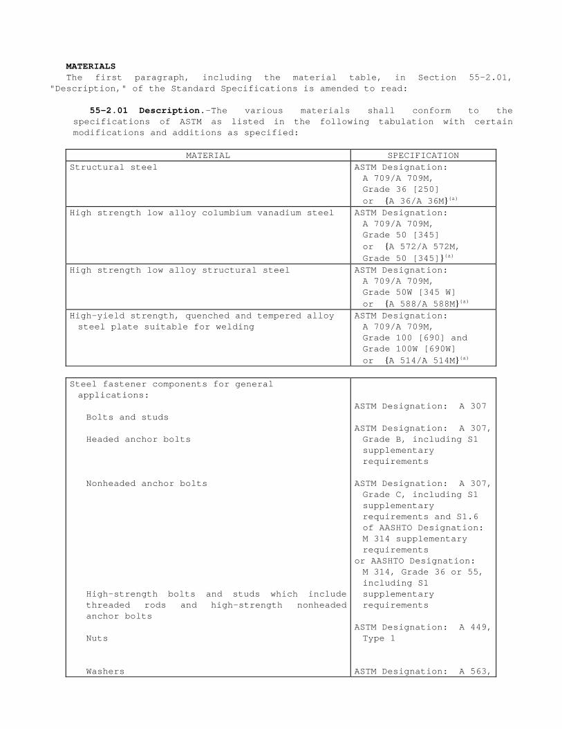
MATERIALS The first
"Description," paragraph, including the of the Standard Specificatio
material table, in ns is amended to read:
Section 552.01,
55-2.01 Description.—The various materials shall conform to the specifications of ASTM as listed in the following tabulation with certain modifications and additions as specified:
MATERIAL SPECIFICATION Structural steel ASTM Designation:
A 709/A 709M, Grade 36 [250] or {A 36/A 36M}(a)
High strength low alloy columbium vanadium steel ASTM Designation: A 709/A 709M, Grade 50 [345] or {A 572/A 572M, Grade 50 [345]}(a)
High strength low alloy structural steel ASTM Designation: A 709/A 709M, Grade 50W [345 W] or {A 588/A 588M}(a)
High-yield strength, quenched and tempered alloy steel plate suitable for welding
ASTM Designation: A 709/A 709M, Grade 100 [690] and Grade 100W [690W] or {A 514/A 514M}(a)
Steel fastener components for general applications:
Bolts and studs ASTM Designation: A 307
Headed anchor bolts ASTM Designation: A 307, Grade B, including S1 supplementary requirements
Nonheaded anchor bolts
High-strength bolts and studs which include threaded rods and high-strength nonheaded anchor bolts
ASTM Designation: A 307, Grade C, including S1 supplementary requirements and S1.6 of AASHTO Designation: M 314 supplementary requirements
or AASHTO Designation: M 314, Grade 36 or 55, including S1 supplementary requirements
Nuts ASTM Designation: A 449, Type 1
Washers ASTM Designation: A 563,

including Appendix X1(b)
ASTM Designation: F 844
CONTRACT NO. 04-0435U4 REVISED PER ADDENDUM NO. 2 DATED JULY 19, 1999
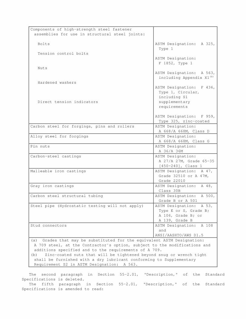
Components of high-strength steel fastener assemblies for use in structural steel joints:
Bolts
Tension control bolts
Nuts
Hardened washers
Direct tension indicators
ASTM Designation: A 325, Type 1
ASTM Designation: F 1852, Type 1
ASTM Designation: A 563, including Appendix X1(b)
ASTM Designation: F 436, Type 1, Circular, including S1 supplementary requirements
ASTM Designation: F 959, Type 325, zinc-coated
Carbon steel for forgings, pins and rollers ASTM Designation: A 668/A 668M, Class D
Alloy steel for forgings ASTM Designation: A 668/A 668M, Class G
Pin nuts ASTM Designation: A 36/A 36M
Carbon-steel castings ASTM Designation: A 27/A 27M, Grade 65-35 [450-240], Class 1
Malleable iron castings ASTM Designation: A 47, Grade 32510 or A 47M, Grade 22010
Gray iron castings ASTM Designation: A 48, Class 30B
Carbon steel structural tubing ASTM Designation: A 500, Grade B or A 501
Steel pipe (Hydrostatic testing will not apply) ASTM Designation: A 53, Type E or S, Grade B; A 106, Grade B; or A 139, Grade B
Stud connectors ASTM Designation: A 108 and
ANSI/AASHTO/AWS D1.5 (a) Grades that may be substituted for the equivalent ASTM Designation: A 709 steel, at the Contractor's option, subject to the modifications and additions specified and to the requirements of A 709.
(b) Zinc-coated nuts that will be tightened beyond snug or wrench tight shall be furnished with a dry lubricant conforming to Supplementary Requirement S2 in ASTM Designation: A 563.
The second paragraph in Section 55-2.01, "Description," of the Standard Specifications is deleted.
The fifth paragraph in Section 55-2.01, "Description," of the Standard Specifications is amended to read:
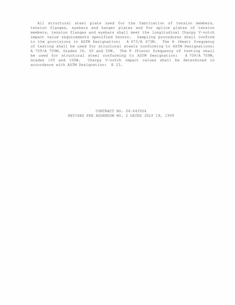
All structural steel plate used for the fabrication of tension members, tension flanges, eyebars and hanger plates and for splice plates of tension members, tension flanges and eyebars shall meet the longitudinal Charpy V-notch impact value requirements specified herein. Sampling procedures shall conform to the provisions in ASTM Designation: A 673/A 673M. The H (Heat) frequency of testing shall be used for structural steels conforming to ASTM Designations: A 709/A 709M, Grades 36, 50 and 50W. The P (Piece) frequency of testing shall be used for structural steel conforming to ASTM Designation: A 709/A 709M, Grades 100 and 100W. Charpy V-notch impact values shall be determined in accordance with ASTM Designation: E 23.
CONTRACT NO. 04-0435U4 REVISED PER ADDENDUM NO. 2 DATED JULY 19, 1999
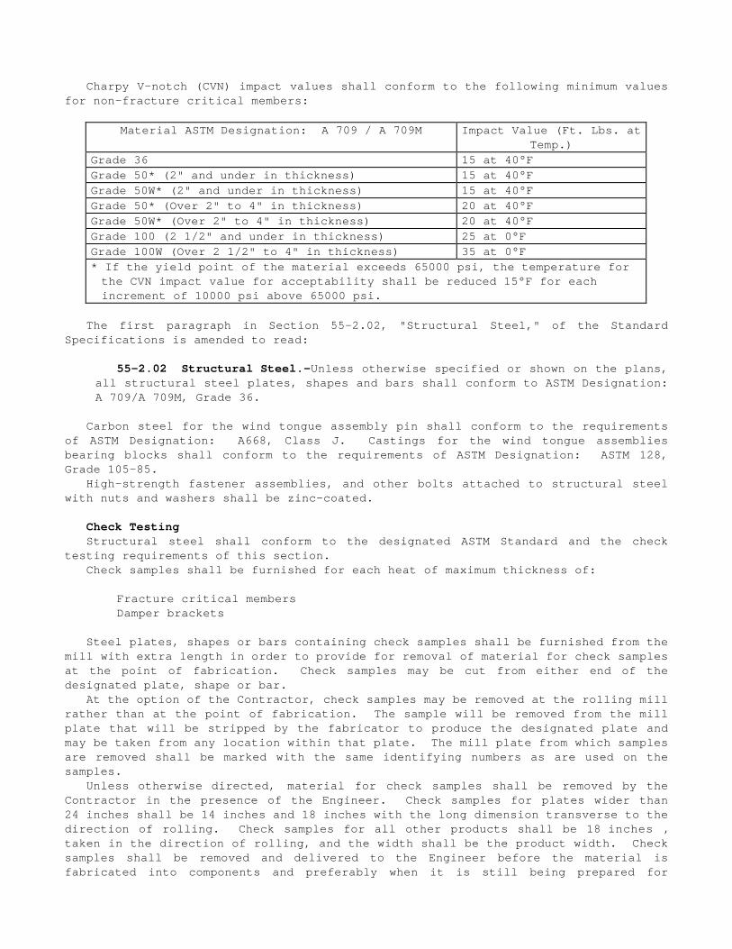
Charpy V-notch (CVN) impact values shall conform to the following minimum values for non-fracture critical members:
Material ASTM Designation: A 709 / A 709M Impact Value (Ft. Lbs. at Temp.)
Grade 36 15 at 40°F Grade 50* (2" and under in thickness) 15 at 40°F Grade 50W* (2" and under in thickness) 15 at 40°F Grade 50* (Over 2" to 4" in thickness) 20 at 40°F Grade 50W* (Over 2" to 4" in thickness) 20 at 40°F Grade 100 (2 1/2" and under in thickness) 25 at 0°F Grade 100W (Over 2 1/2" to 4" in thickness) 35 at 0°F * If the yield point of the material exceeds 65000 psi, the temperature for the CVN impact value for acceptability shall be reduced 15°F for each increment of 10000 psi above 65000 psi.
The first paragraph in Section 55-2.02, "Structural Steel," of the Standard Specifications is amended to read:
55-2.02 Structural Steel.—Unless otherwise specified or shown on the plans, all structural steel plates, shapes and bars shall conform to ASTM Designation: A 709/A 709M, Grade 36.
Carbon steel for the wind tongue assembly pin shall conform to the requirements of ASTM Designation: A668, Class J. Castings for the wind tongue assemblies bearing blocks shall conform to the requirements of ASTM Designation: ASTM 128, Grade 105-85.
High-strength fastener assemblies, and other bolts attached to structural steel with nuts and washers shall be zinc-coated.
Check Testing Structural steel shall conform to the designated ASTM Standard and the check
testing requirements of this section. Check samples shall be furnished for each heat of maximum thickness of:
Fracture critical members Damper brackets
Steel plates, shapes or bars containing check samples shall be furnished from the mill with extra length in order to provide for removal of material for check samples at the point of fabrication. Check samples may be cut from either end of the designated plate, shape or bar.
At the option of the Contractor, check samples may be removed at the rolling mill rather than at the point of fabrication. The sample will be removed from the mill plate that will be stripped by the fabricator to produce the designated plate and may be taken from any location within that plate. The mill plate from which samples are removed shall be marked with the same identifying numbers as are used on the samples.
Unless otherwise directed, material for check samples shall be removed by the Contractor in the presence of the Engineer. Check samples for plates wider than 24 inches shall be 14 inches and 18 inches with the long dimension transverse to the direction of rolling. Check samples for all other products shall be 18 inches , taken in the direction of rolling, and the width shall be the product width. Check samples shall be removed and delivered to the Engineer before the material is fabricated into components and preferably when it is still being prepared for
fabrication. The direction of rolling, heat numbers, and plate numbers shall be marked on the samples with paint or other indelible marking material or may be steel stamped in one corner of the plate.
Unless otherwise directed, check samples shall be delivered to the Transportation Laboratory at the Contractor's expense. The check samples will be tested by the Transportation Laboratory for compliance with the requirements specified in ASTM and these special provisions. Check sample test results will be reported to the Contractor within 10 working days of delivery to the Transportation Laboratory. In the event several samples are submitted on the same day, an additional day will be added for each 2 samples submitted. The test report will be made for the group of samples.
The results of the tensile and impact tests shall not vary more than 5 percent below specified minimum or 5 percent above specified maximum requirements except that if the initial check test results vary more than 5 percent but not more than 10 percent from the specified requirements, a retest may be performed on another sample from the same heat and thickness. The results of the retest shall not vary more than 5 percent from the original specified requirements. If the results of check tests exceed these permissible variations, material planned for use from the heat represented by said check samples shall be subject to rejection.
CONTRACT NO. 04-0435U4 REVISED PER ADDENDUM NO. 2 DATED JULY 19, 1999

FABRICATION The first paragraph of Section 55-3.05, "Facing and Bearing Surfaces," of the
Standard Specifications is amended to read:
55-3.05 Flatness of Faying and Bearing Surfaces.—Surfaces of bearing and base plates and other metal surfaces that are to come in contact with each other or with ground concrete surfaces or with asbestos sheet packing shall be flat to within 1/32 inch tolerance in 12 inches and to within 1/16 inch tolerance overall. Surfaces of bearing and base plates and other metal bearing surfaces that are to come in contact with preformed fabric pads, elastomeric bearing pads or portland cement mortar shall be flat to within 1/8 inch tolerance in 12 inches and to within 3/16 inch tolerance overall.
Machine-finished surfaces, including the inside surface of the bearing block and pin for the wind tongues, shall be coated as soon as practicable after being accepted, and before removal from the shop, with a corrosion inhibitor. Surfaces of iron and steel castings, machine-finished for the sole purpose of removing scales, scabs, fins, blisters or other surface deformations, shall not be so coated.
The corrosion inhibitor used for coating machine-finished surfaces shall provide a long-term, firm waxy film, resistant to humidity and salt spray and be nonhardening. The corrosion inhibitor shall be a commercially manufactured product for protecting machined surfaces subjected to long periods of storage or adverse conditions during shipment. Before final assembly, the corrosion inhibitor shall be completely removed.
Paragraphs 1 through 5, excluding Section 55-3.14A, of Section 55-3.14, "Bolted Connections," of the Standard Specifications are amended to read:
55-3.14 Bolted Connections.—Bolted connections in structural steel joints, unless otherwise shown on the plans or specified in the special provisions, shall be made with high-strength steel fastener assemblies. These fastener assemblies shall consist of either 1) a high-strength steel bolt, nut and hardened washer or 2) a tension control bolt, nut and hardened washer. A direct tension indicator (DTI) may be used with the high-strength bolt, nut and hardened washer assembly.
Bolted connections using fastener assemblies shall conform to the requirements in "Specification for Structural Joints Using ASTM A 325 or A 490 Bolts" (RCSC Specification) approved by the Research Council on Structural Connections of the Engineering Foundation, and these specifications.
When reference is made to the RCSC Specification, the "Allowable Stress Design" version shall be used when allowable stress design is shown on the plans and the "Load and Resistance Factor Design" version shall be used when load factor design or load and resistance factor design is shown on the plans.
All connections made with fastener assemblies shall be tensioned as a slip critical connection, whether classified as a slip critical or bearing type connection, unless otherwise designated on the plans.
The hardened washer shall be installed under the nut or bolt head, whichever is the element turned in tightening. Nuts shall be located, wherever practicable, on the side of the member that will not be visible from the traveled way. Nuts for bolts that will be partially embedded in concrete shall be located on the side of the member that will be encased in concrete.
When the bolt head is used as the turned element, all tension testing and tension verification, including determining job inspecting torque, shall be performed by turning the bolt head.
Each length and diameter of fastener assemblies used in any one joint of a high-strength bolted connection shall be from the same rotational capacity lot.
The Contractor shall keep a record of which rotational capacity lots are used in each joint.
The Contractor shall provide, calibrate and maintain the equipment and tools necessary for the preliminary testing, installation and inspection of all fasteners.
Bolt tension measuring devices and calibrated wrenches shall be calibrated within one year prior to first being used on the job, and a minimum of once each year thereafter. This calibration shall be done by a qualified independent laboratory or authorized warranty repair and calibration center recognized by the tool manufacturer. Bolt tension measuring devices shall be calibrated, to within one percent of the actual tension value, with a minimum of 4 verification readings evenly spaced over a range of 20 to 80 percent of full scale. Calibrated wrenches shall be calibrated to within 2 percent of the actual torque value, with a minimum of 4 verification readings evenly spaced over a range of 20 to 100 percent of full scale. Test equipment used for certification and calibration standards shall be traceable to the National Institute of Standards and Technology.
CONTRACT NO. 04-0435U4 REVISED PER ADDENDUM NO. 2 DATED JULY 19, 1999
If a torque multiplier is used in conjunction with a calibrated wrench as a method for tightening fastener assemblies to the required tension, both the multiplier and the wrench shall be calibrated together as a system. The same length input and output sockets and extensions that will be used in the work shall also be included in the calibration of the system. The manufacturer's torque multiplication ratio shall be adjusted during calibration of the system, such that when this adjusted ratio is multiplied by the actual input calibrated wrench reading, the product is a calculated output torque that is within 2 percent of the true output torque. When this system is used in the work to perform any installation tension testing, rotational capacity testing, fastener tightening, or tension verification, it shall be used, intact as calibrated.
Prior to the use of bolt tension measuring devices or calibrated wrenches, the Contractor shall furnish to the Engineer certificates of calibration with plots of verification readings for each device or wrench.
In addition to the submittals required in Section 55-1.03, "Inspection," the Contractor shall furnish certified test reports of tests on fastener components and fastener assemblies performed prior to shipment to the job-site. Certified test reports for fastener components and fastener assemblies shall be furnished to the Engineer prior to use of the fastener assembly. The certified test reports shall include the rotational capacity lot numbers for fastener assemblies supplied and all test reports specified in the "Certification," "Report," "Number of Tests and Retests," and "Certification and Test Report" sections in the appropriate ASTM specifications for the fastener components. For ASTM Designation A307, Grade B or Grade C anchor bolts, the chemical composition and calculated carbon equivalent of each heat of steel shall be furnished.
All bolted connection surfaces shall be prepared before assembly in conformance with the requirements in the special provisions.
High-strength steel fasteners shall consist of a tension control bolt, nut and hardened washer, whenever practicable. Direct tension indicators shall not be used at any location. Tension control bolt heads shall be round (button-head) and shall be oriented to match the appearance of the existing adjacent rivets, whenever practicable.
High-strength bolted connections using A 490 bolts shall be installed with two hardened washers on the side of the member that will be visible from the traveled way.
Countersunk bolts shall be furnished with a suitable nut and washer and conform to the requirements of ASTM Designation: A449. Countersunk bolts shall have heads conforming to dimensions, tolerances and requirements listed in ANSI/ASME B18.3, for hexagonal socket flat countersunk head cap screws, and shall be marked in accordance to the requirements of ASTM Designation: A449. The conical bearing surface of the head shall have a depressed hex slot in the head and shall be free from fins, seams, irregular surfaces which prevent full bearing and other defects affecting their serviceability. When installed the top surface of the head of countersunk bolts shall not project above the adjacent structural steel surface and may be recessed not more than 1/16 inch from the adjacent steel surface.
Steel fasteners, including bolts and studs, designated on the plans as A 354, Grade BC, shall conform to the requirements of ASTM Designation: A 354, Grade BC. Steel fastener components for steel fasteners designated as A 354, Grade BC shall include a bolt or stud, as shown on the plans, nut and hardened washer. Nuts for steel fasteners designated as A 354, Grade BC shall conform to Section 55-2.01, "Description," of the Standard Specifications. Nuts shall be zinc coated and be furnished with a dry lubricant conforming to Supplementary Requirement S1 and S2 in ASTM Designation: A 563.
Holes for bolted connections in structural steel joints consisting of new and existing structural steel or existing structural steel may consist of both sub

punched or sub-drilled holes and holes punched or drilled full size as approved by the Engineer and shall conform to these special provisions.
The finished holes in structural steel plates nearest to the nut or bolt head shall not be more than 1/16 inch larger than the nominal diameter of the bolt.
When the holes in other existing structural steel plate are 1/16 inch larger than the nominal diameter of the bolt, the holes may be reamed to slots conforming to the provisions for short-slotted holes as defined in "Specification for Structural Joints Using ASTM A325 or A490 Bolts" (RCSC Specification) approved by the Research Council on Structural Connections. The axis of the slot in short-slotted holes in existing interior plies shall be normal to the direction of the load.
Bolts with diameters up to 1/4 inch larger than the diameter of the bolt shown on the plans may be used, provided that the required clearances and edge distances are not reduced below that required for the larger bolt and the remaining net section of the structural steel plate is adequate.
Section 55-3.14, "Bolted Connections," of the Standard Specifications is amended by adding the following paragraphs:
55-3.14B Installation.—If any components of fastener assemblies are furnished with water soluble lubricants, fastener installation will not be permitted when surface moisture is present at a high-strength bolted connection. If fastener assemblies are furnished with other than water soluble lubricants, the Engineer may require the Contractor to perform additional fastener testing if any fastener work or testing is performed when surface moisture is present.
CONTRACT NO. 04-0435U4 REVISED PER ADDENDUM NO. 2 DATED JULY 19, 1999

Manual torque wrenches shall have either a dial gage or digital read out. Any electric, pneumatic or hydraulic calibrated wrench used to tension fasteners shall have an adjustable control unit that can be set to positively shut off at the desired torque.
Wrenches used for snugging tension control bolts in a connection prior to final tensioning shall not apply torsion to the splined end of the bolt.
The threaded ends of fastener assemblies projecting past the outer face of the nut (thread stickout), where first full formed threads are present, shall be at least flush with, but not extend more than 1/4 inch beyond, the outer face of the nut. A maximum of one hardened washer, in addition to the single washer required under the turned element, may be installed under the nonturning element of the fastener assembly. The thread stickout of studs, rods and anchor bolts, shall be at least 1/8 inch , and there shall be a minimum of 3 full threads located within the grip of the connection. In addition, a minimum of 3 full threads shall be located between the bearing surfaces of the bolt head and nut. The total stickout shall not be excessive.
Larger bolts, having diameters up to 1/4 inch greater than the diameter of the bolt shown on the plans, may be used if approved by the Engineer provided that spacing and edge distance requirements for the larger bolt are met and the net section is adequate.
When DTIs are used, one DTI shall be installed under each bolt head with the DTI protrusions contacting the bearing surface of the bolt head. To tension the bolt, the bolt head shall be held stationary and the nut turned. Unless otherwise specified, manufacturer’s installation procedures shall be followed. Each bolt shall be tensioned in at least 2 tightening stages until at least 50 percent of the gaps on each DTI are greater than zero and less than 0.005 inch. Complete crushing of all DTI protrusions (0 gaps) on any given DTI will be cause for rejection.
The same head orientation shall be used within any one high-strength bolted connection.
55-3.14C Rotational Capacity Testing Prior to Shipment to Job Site.— Rotational capacity tests on fastener assemblies shall be performed as specified in the special provisions.
55-3.14D Installation Tension Testing and Rotational Capacity Testing After Arrival to Job Site.—Installation tension tests and rotational capacity tests on fastener assemblies shall be performed as specified in the special provisions.
55-3.14E Tension Verification of Fastener Assemblies.—Minimum fastener tension in all completed high-strength bolted connections shall be verified.
For each type of fastener assembly, at least 10 percent, but no fewer than 2 assemblies of each rotational capacity lot used in each high-strength bolted connection shall be checked for minimum tension, by the Contractor, in conformance with the procedure described in Section 9(b), "Arbitration Inspection," of the RCSC Specification. For determining the job inspecting torque for short bolts, the procedure described in steps 1 through 9 of the "Arbitration of Disputes, Inspection Torque Method-Short Bolts," section of the "Structural Bolting Handbook," published by the Steel Structures Technology Center, Incorporated shall replace Section 9(b)(2) of the RCSC Specification. A separate inspecting torque shall be determined and used for each different rotational capacity lot of fasteners.
The verification for minimum tension shall be performed 1) no longer than 48 hours after all fasteners in the connection have been tensioned, 2) on fastener assemblies selected by the Engineer, 3) in the presence of the Engineer, and 4)
in such a manner that the Engineer can read the torque wrench gage or access the DTI gaps during inspection.
Rotational Capacity Testing Prior to Shipment to Job Site Rotational capacity tests shall be performed on all lots of high-strength
fastener assemblies prior to shipment of these lots to the job site. Zinc-coated assemblies shall be tested after all fabrication, coating and lubrication of components have been completed. One hardened washer shall be used under each nut for the tests.
Each combination of bolt production lot, nut lot and washer lot shall be tested as an assembly.
A rotational capacity lot number shall be assigned to each combination of lots tested. Each shipping unit of fastener assemblies shall be plainly marked with the rotational capacity lot number.
Two fastener assemblies from each rotational capacity lot shall be tested. The following equipment, procedure and acceptance criteria shall be used to
perform rotational capacity tests on, and determine acceptance of long bolts. Fasteners are considered to be long bolts when full nut thread engagement can be achieved when installed in a bolt tension measuring device.
CONTRACT NO. 04-0435U4 REVISED PER ADDENDUM NO. 2 DATED JULY 19, 1999
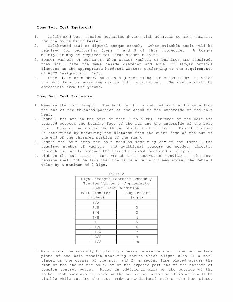
Long Bolt Test Equipment:
1. Calibrated bolt tension measuring device with adequate tension capacity for the bolts being tested.
2. Calibrated dial or digital torque wrench. Other suitable tools will be required for performing Steps 7 and 8 of this procedure. A torque multiplier may be required for large diameter bolts.
3. Spacer washers or bushings. When spacer washers or bushings are required, they shall have the same inside diameter and equal or larger outside diameter as the appropriate hardened washers conforming to the requirements of ASTM Designation: F436.
4. Steel beam or member, such as a girder flange or cross frame, to which the bolt tension measuring device will be attached. The device shall be accessible from the ground.
Long Bolt Test Procedure:
1. Measure the bolt length. The bolt length is defined as the distance from the end of the threaded portion of the shank to the underside of the bolt head.
2. Install the nut on the bolt so that 3 to 5 full threads of the bolt are located between the bearing face of the nut and the underside of the bolt head. Measure and record the thread stickout of the bolt. Thread stickout is determined by measuring the distance from the outer face of the nut to the end of the threaded portion of the shank.
3. Insert the bolt into the bolt tension measuring device and install the required number of washers, and additional spacers as needed, directly beneath the nut to produce the thread stickout measured in Step 2.
4. Tighten the nut using a hand wrench to a snug-tight condition. The snug tension shall not be less than the Table A value but may exceed the Table A value by a maximum of 2 kips.
Table A High-Strength Fastener Assembly Tension Values to Approximate
Snug-Tight Condition Bolt Diameter
(inches) Snug Tension
(kips) 1/2 1 5/8 2 3/4 3 7/8 4 1 5
1 1/8 6 1 1/4 7 1 3/8 9 1 1/2 10
5. Match-mark the assembly by placing a heavy reference start line on the face plate of the bolt tension measuring device which aligns with 1) a mark placed on one corner of the nut, and 2) a radial line placed across the flat on the end of the bolt, or on the exposed portions of the threads of tension control bolts. Place an additional mark on the outside of the socket that overlays the mark on the nut corner such that this mark will be visible while turning the nut. Make an additional mark on the face plate,
either 2/3 of a turn, one turn, or 1 1/3 turn clockwise from the heavy reference start line, depending on the bolt length being tested as shown in Table B.
CONTRACT NO. 04-0435U4 REVISED PER ADDENDUM NO. 2 DATED JULY 19, 1999
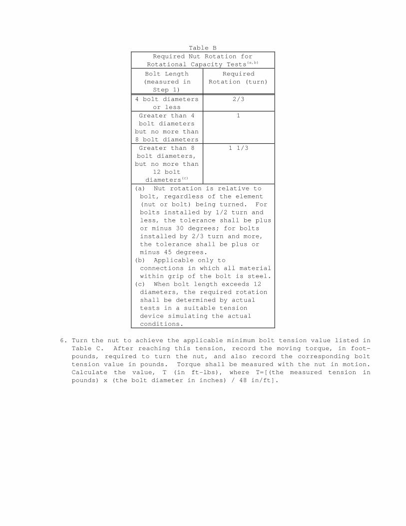
Table B Required Nut Rotation for
Rotational Capacity Tests(a,b)
Bolt Length (measured in
Step 1)
Required Rotation (turn)
4 bolt diameters or less
2/3
Greater than 4 bolt diameters
but no more than 8 bolt diameters
1
Greater than 8 bolt diameters, but no more than
12 bolt diameters(c)
1 1/3
(a) Nut rotation is relative to bolt, regardless of the element (nut or bolt) being turned. For bolts installed by 1/2 turn and less, the tolerance shall be plus or minus 30 degrees; for bolts installed by 2/3 turn and more, the tolerance shall be plus or minus 45 degrees.
(b) Applicable only to connections in which all material within grip of the bolt is steel.
(c) When bolt length exceeds 12 diameters, the required rotation shall be determined by actual tests in a suitable tension device simulating the actual conditions.
6. Turn the nut to achieve the applicable minimum bolt tension value listed in Table C. After reaching this tension, record the moving torque, in footpounds, required to turn the nut, and also record the corresponding bolt tension value in pounds. Torque shall be measured with the nut in motion. Calculate the value, T (in ft-lbs), where T=[(the measured tension in pounds) x (the bolt diameter in inches) / 48 in/ft].
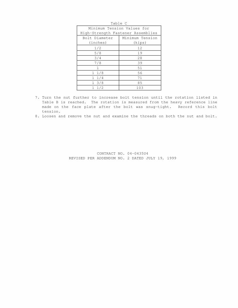
Table C Minimum Tension Values for
High-Strength Fastener Assemblies Bolt Diameter
(inches) Minimum Tension
(kips) 1/2 12 5/8 19 3/4 28 7/8 39 1 51
1 1/8 56 1 1/4 71 1 3/8 85 1 1/2 103
7. Turn the nut further to increase bolt tension until the rotation listed in Table B is reached. The rotation is measured from the heavy reference line made on the face plate after the bolt was snug-tight. Record this bolt tension.
8. Loosen and remove the nut and examine the threads on both the nut and bolt.
CONTRACT NO. 04-0435U4 REVISED PER ADDENDUM NO. 2 DATED JULY 19, 1999
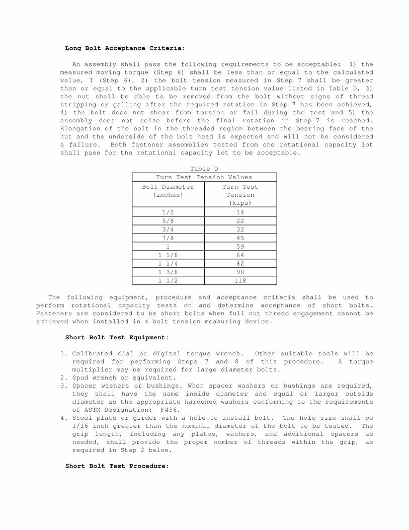
Long Bolt Acceptance Criteria:
An assembly shall pass the following requirements to be acceptable: 1) the measured moving torque (Step 6) shall be less than or equal to the calculated value, T (Step 6), 2) the bolt tension measured in Step 7 shall be greater than or equal to the applicable turn test tension value listed in Table D, 3) the nut shall be able to be removed from the bolt without signs of thread stripping or galling after the required rotation in Step 7 has been achieved, 4) the bolt does not shear from torsion or fail during the test and 5) the assembly does not seize before the final rotation in Step 7 is reached. Elongation of the bolt in the threaded region between the bearing face of the nut and the underside of the bolt head is expected and will not be considered a failure. Both fastener assemblies tested from one rotational capacity lot shall pass for the rotational capacity lot to be acceptable.
Table D Turn Test Tension Values
Bolt Diameter (inches)
Turn Test Tension (kips)
1/2 14 5/8 22 3/4 32 7/8 45 1 59
1 1/8 64 1 1/4 82 1 3/8 98 1 1/2 118
The following equipment, procedure and acceptance criteria shall be used to perform rotational capacity tests on and determine acceptance of short bolts. Fasteners are considered to be short bolts when full nut thread engagement cannot be achieved when installed in a bolt tension measuring device.
Short Bolt Test Equipment:
1. Calibrated dial or digital torque wrench. Other suitable tools will be required for performing Steps 7 and 8 of this procedure. A torque multiplier may be required for large diameter bolts.
2. Spud wrench or equivalent. 3. Spacer washers or bushings. When spacer washers or bushings are required,
they shall have the same inside diameter and equal or larger outside diameter as the appropriate hardened washers conforming to the requirements of ASTM Designation: F436.
4. Steel plate or girder with a hole to install bolt. The hole size shall be 1/16 inch greater than the nominal diameter of the bolt to be tested. The grip length, including any plates, washers, and additional spacers as needed, shall provide the proper number of threads within the grip, as required in Step 2 below.
Short Bolt Test Procedure:
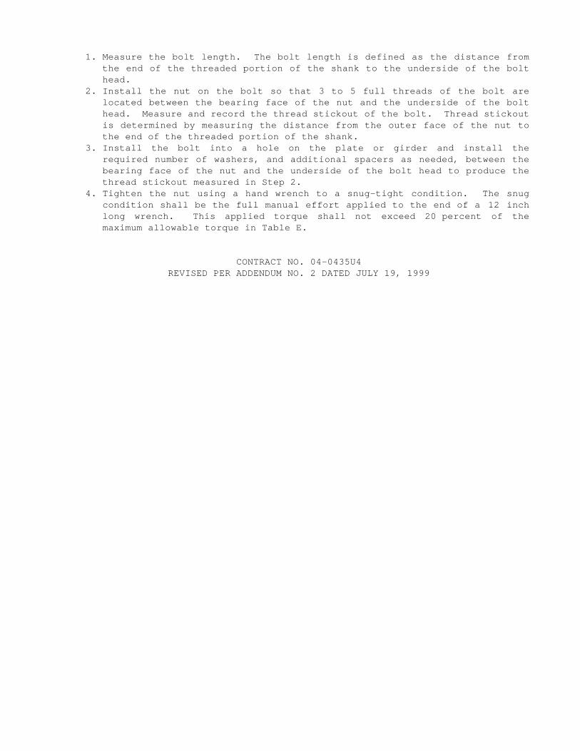
1. Measure the bolt length. The bolt length is defined as the distance from the end of the threaded portion of the shank to the underside of the bolt head.
2. Install the nut on the bolt so that 3 to 5 full threads of the bolt are located between the bearing face of the nut and the underside of the bolt head. Measure and record the thread stickout of the bolt. Thread stickout is determined by measuring the distance from the outer face of the nut to the end of the threaded portion of the shank.
3. Install the bolt into a hole on the plate or girder and install the required number of washers, and additional spacers as needed, between the bearing face of the nut and the underside of the bolt head to produce the thread stickout measured in Step 2.
4. Tighten the nut using a hand wrench to a snug-tight condition. The snug condition shall be the full manual effort applied to the end of a 12 inch long wrench. This applied torque shall not exceed 20 percent of the maximum allowable torque in Table E.
CONTRACT NO. 04-0435U4 REVISED PER ADDENDUM NO. 2 DATED JULY 19, 1999
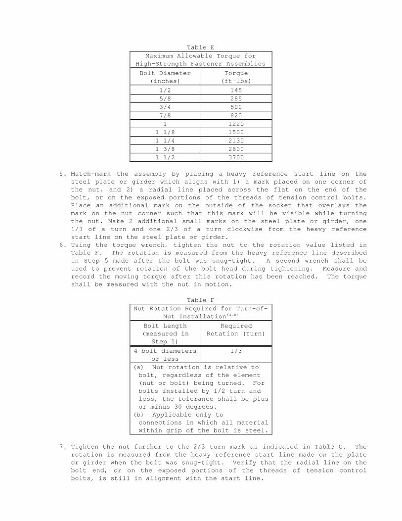
Table E Maximum Allowable Torque for
High-Strength Fastener Assemblies Bolt Diameter
(inches) Torque
(ft-lbs) 1/2 145 5/8 285 3/4 500 7/8 820 1 1220
1 1/8 1500 1 1/4 2130 1 3/8 2800 1 1/2 3700
5. Match-mark the assembly by placing a heavy reference start line on the steel plate or girder which aligns with 1) a mark placed on one corner of the nut, and 2) a radial line placed across the flat on the end of the bolt, or on the exposed portions of the threads of tension control bolts. Place an additional mark on the outside of the socket that overlays the mark on the nut corner such that this mark will be visible while turning the nut. Make 2 additional small marks on the steel plate or girder, one 1/3 of a turn and one 2/3 of a turn clockwise from the heavy reference start line on the steel plate or girder.
6. Using the torque wrench, tighten the nut to the rotation value listed in Table F. The rotation is measured from the heavy reference line described in Step 5 made after the bolt was snug-tight. A second wrench shall be used to prevent rotation of the bolt head during tightening. Measure and record the moving torque after this rotation has been reached. The torque shall be measured with the nut in motion.
Table F Nut Rotation Required for Turn-of-
Nut Installation(a,b)
Bolt Length (measured in
Step 1)
Required Rotation (turn)
4 bolt diameters or less
1/3
(a) Nut rotation is relative to bolt, regardless of the element (nut or bolt) being turned. For bolts installed by 1/2 turn and less, the tolerance shall be plus or minus 30 degrees.
(b) Applicable only to connections in which all material within grip of the bolt is steel.
7. Tighten the nut further to the 2/3 turn mark as indicated in Table G. The rotation is measured from the heavy reference start line made on the plate or girder when the bolt was snug-tight. Verify that the radial line on the bolt end, or on the exposed portions of the threads of tension control bolts, is still in alignment with the start line.
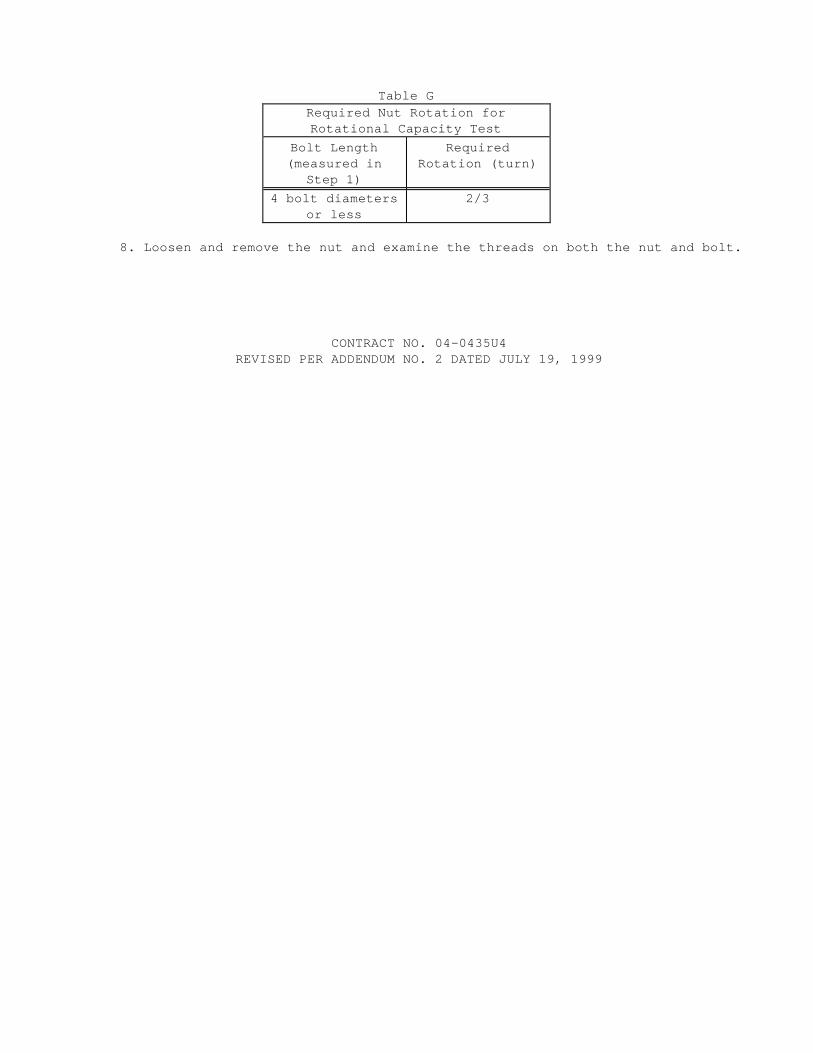
Table G Required Nut Rotation for Rotational Capacity Test
Bolt Length (measured in
Step 1)
Required Rotation (turn)
4 bolt diameters or less
2/3
8. Loosen and remove the nut and examine the threads on both the nut and bolt.
CONTRACT NO. 04-0435U4 REVISED PER ADDENDUM NO. 2 DATED JULY 19, 1999

Short Bolt Acceptance Criteria:
An assembly shall pass the following requirements to be acceptable: 1) the measured moving torque from Step 6 shall be less than or equal to the maximum allowable torque from Table E, 2) the nut shall be able to be removed from the bolt without signs of thread stripping or galling after the required rotation in Step 7 has been achieved, 3) the bolt does not shear from torsion or fail during the test and 4) the assembly does not seize before the final rotation in Step 7 is reached. Elongation of the bolt in the threaded region between the bearing face of the nut and the underside of the bolt head will not be considered a failure. Both fastener assemblies tested from one rotational capacity lot shall pass for the rotational capacity lot to be acceptable.
Installation Tension Testing and Rotational Capacity Testing After Arrival on Job Site
Installation tension tests and rotational capacity tests on high-strength fastener assemblies shall be performed by the Contractor prior to acceptance or installation, and after arrival of the fastener assemblies on the job-site. The installation tension tests and rotational capacity tests shall be performed at the job-site, in the presence of the Engineer, on each rotational capacity lot of fastener assemblies.
Installation tension tests shall be performed on 3 representative fastener assemblies in conformance with Section 8, "Installation and Tightening," of the RCSC Specification. For short bolts, Section 8(d), "Joint Assembly and Tightening of Slip-Critical and Direct Tension Connections," of the RCSC Specification shall be replaced by the "Pre-Installation Testing Procedures," of the "Structural Bolting Handbook," published by the Steel Structures Technology Center, Incorporated.
The rotational capacity tests shall be performed in conformance with the requirements for rotational capacity tests in "Rotational Capacity Testing Prior to Shipment to Job Site" of these special provisions.
At the Contractor's expense, additional installation tension tests, tests required to determine job inspecting torque and rotational capacity tests shall be performed by the Contractor on each rotational capacity lot, in the presence of the Engineer, if 1) any fastener is not used within 3 months after arrival on the jobsite, 2) fasteners are improperly handled, stored, or subjected to inclement weather prior to final tightening, 3) significant changes are noted in original surface condition of threads, washers or nut lubricant or 4) the Contractor's required inspection is not performed within 48 hours after all fasteners in a joint have been tensioned.
Failure of a job-site installation tension test or a rotational capacity test will be cause for rejection of unused fasteners which are part of the rotational capacity lot.
Steel fasteners designated as on the plans as A 449 shall be tensioned not less than the value shown on the plans. Prior to installation, the Contractor shall submit to the Engineer for approval the methods and equipment to be used to tension steel fasteners designated as ASTM Designation: A 449 in accordance with Section 55-1.02, "Drawings," of the Standard Specifications. Direct tension indicators shall not be used. The plans shall include methods and equipment to be used to evaluate: 1) the presence of a lubricant, 2) the efficiency of the lubricant, and 3) the compatibility of the high strength steel bolt, nut conforming to Supplementary Requirement S1 and S2 in ASTM Designation: A 563 and hardened washer.
Steel fasteners designated on the plans as A 354, Grade BC shall be tensioned not less than the value shown on the plans. Prior to installation, the Contractor shall submit to the Engineer for approval the methods and equipment to be used to tension steel fasteners designated as A354, Grade BC in accordance with Section 55-1.02, "Drawings," of the Standard Specifications. Direct tension indicators shall not be

used. The plans shall include methods and equipment to be used to evaluate: 1) the presence of a lubricant, 2) the efficiency of the lubricant, and 3) the compatibility of the high strength steel bolt, nut and hardened washer.
Surface Preparation For all bolted connections, the 1) contact surfaces, 2) surfaces of outside
existing members within the grip under bolt heads, nuts and washers and 3) inside surfaces of bolt holes shall be cleaned and coated before assembly in conformance with the provisions for cleaning and painting structural steel of these special provisions.
When zinc-coated tension control bolts are used, the sheared end of each fastener shall be completely sealed with non-silicone type sealing compound conforming to the provisions in Federal Specification TT-S-230, Type II. The sealant shall be gray in color and shall have a minimum thickness of 50 mils.. The sealant shall be applied to a clean sheared surface on the same day that the splined end is sheared off.
Welding The third paragraph of Section 55-3.17, "Welding," of the Standard
Specifications is amended to read:
In addition to the nondestructive testing requirements in ANSI/AASHTO/AWS D1.5, 25 percent of all main member tension groove welds, in material in excess of 1/2 inch thickness, shall be ultrasonically tested.
CONTRACT NO. 04-0435U4 REVISED PER ADDENDUM NO. 2 DATED JULY 19, 1999

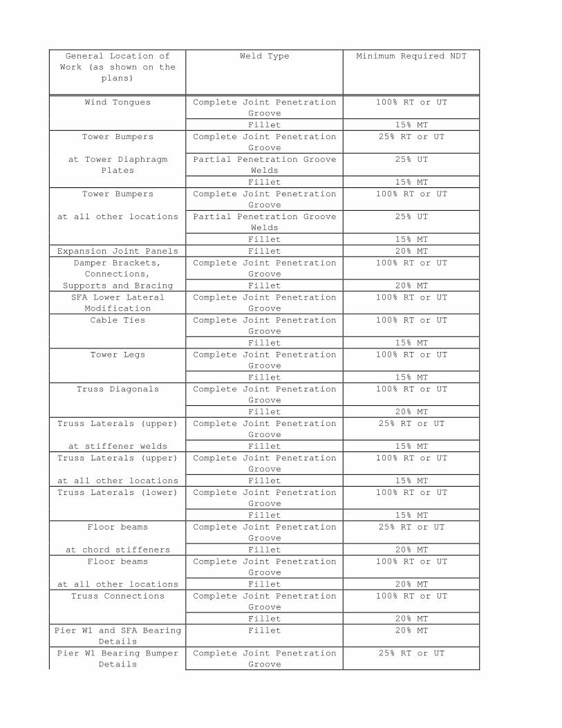
In addition to the requirements of the Standard Specifications, special provisions and AWS D1.5, the following nondestructive testing (NDT) shall be performed:
General Location of Work (as shown on the
plans)
Weld Type Minimum Required NDT
Wind Tongues Complete Joint Penetration Groove
100% RT or UT
Fillet 15% MT Tower Bumpers
at Tower Diaphragm Plates
Complete Joint Penetration Groove
25% RT or UT
Partial Penetration Groove Welds
25% UT
Fillet 15% MT Tower Bumpers
at all other locations
Complete Joint Penetration Groove
100% RT or UT
Partial Penetration Groove Welds
25% UT
Fillet 15% MT Expansion Joint Panels Fillet 20% MT
Damper Brackets, Connections,
Supports and Bracing
Complete Joint Penetration Groove
100% RT or UT
Fillet 20% MT SFA Lower Lateral
Modification Complete Joint Penetration
Groove 100% RT or UT
Cable Ties Complete Joint Penetration Groove
100% RT or UT
Fillet 15% MT Tower Legs Complete Joint Penetration
Groove 100% RT or UT
Fillet 15% MT Truss Diagonals Complete Joint Penetration
Groove 100% RT or UT
Fillet 20% MT Truss Laterals (upper)
at stiffener welds
Complete Joint Penetration Groove
25% RT or UT
Fillet 15% MT Truss Laterals (upper)
at all other locations
Complete Joint Penetration Groove
100% RT or UT
Fillet 15% MT Truss Laterals (lower) Complete Joint Penetration
Groove 100% RT or UT
Fillet 15% MT Floor beams
at chord stiffeners
Complete Joint Penetration Groove
25% RT or UT
Fillet 20% MT Floor beams
at all other locations
Complete Joint Penetration Groove
100% RT or UT
Fillet 20% MT Truss Connections Complete Joint Penetration
Groove 100% RT or UT
Fillet 20% MT Pier W1 and SFA Bearing
Details Fillet 20% MT
Pier W1 Bearing Bumper Details
Complete Joint Penetration Groove
25% RT or UT
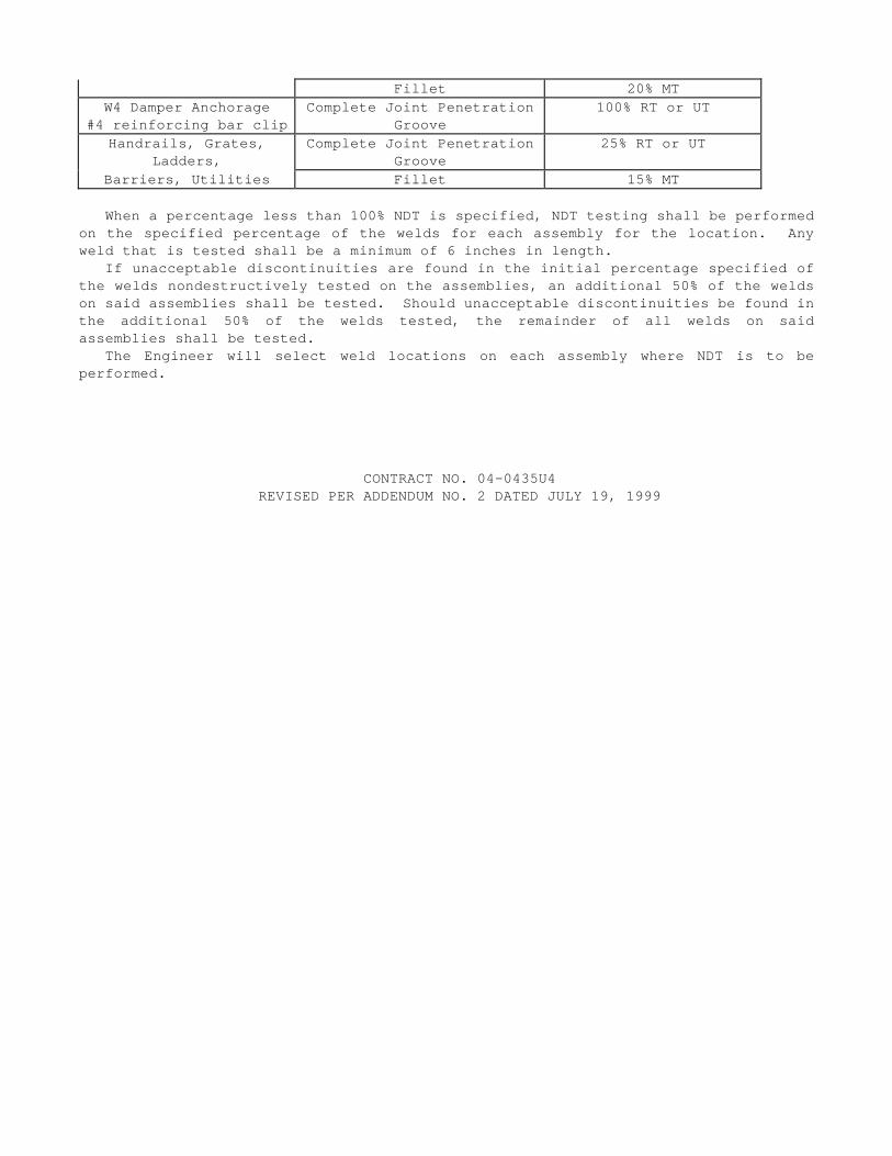
Fillet 20% MT W4 Damper Anchorage
#4 reinforcing bar clip Complete Joint Penetration
Groove 100% RT or UT
Handrails, Grates, Ladders,
Complete Joint Penetration Groove
25% RT or UT
Barriers, Utilities Fillet 15% MT
When a percentage less than 100% NDT is specified, NDT testing shall be performed on the specified percentage of the welds for each assembly for the location. Any weld that is tested shall be a minimum of 6 inches in length.
If unacceptable discontinuities are found in the initial percentage specified of the welds nondestructively tested on the assemblies, an additional 50% of the welds on said assemblies shall be tested. Should unacceptable discontinuities be found in the additional 50% of the welds tested, the remainder of all welds on said assemblies shall be tested.
The Engineer will select weld locations on each assembly where NDT is to be performed.
CONTRACT NO. 04-0435U4 REVISED PER ADDENDUM NO. 2 DATED JULY 19, 1999
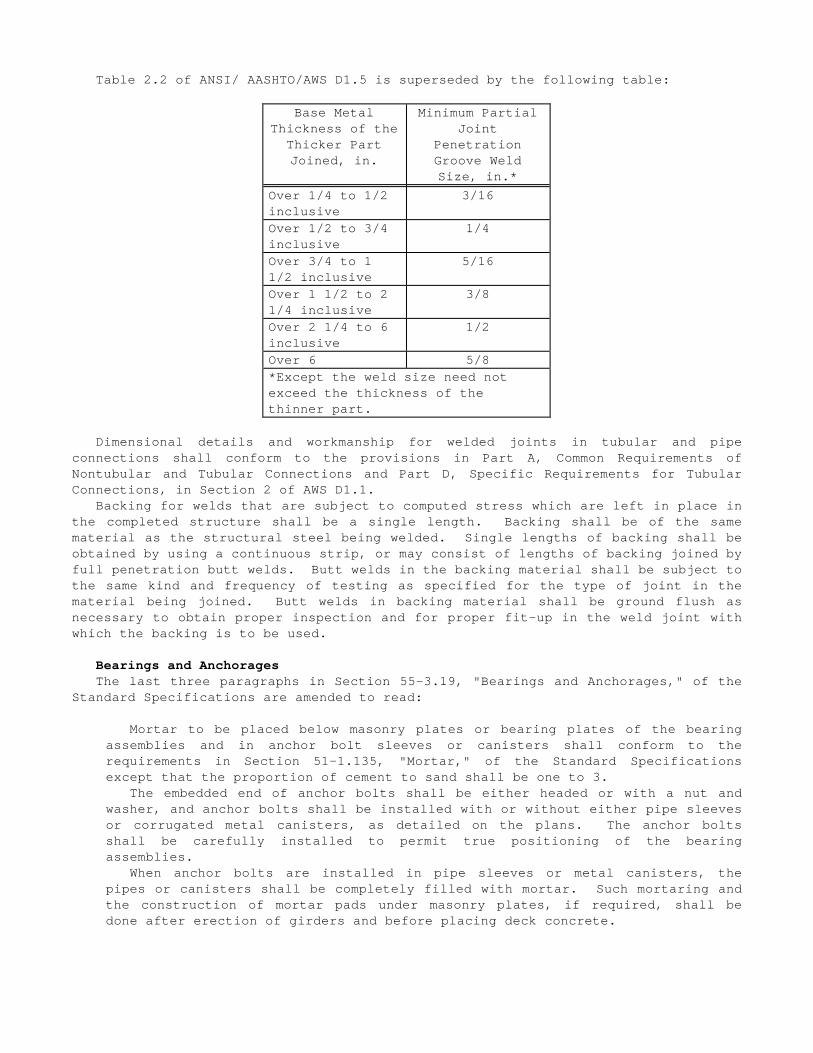
Table 2.2 of ANSI/ AASHTO/AWS D1.5 is superseded by the following table:
Base Metal Thickness of the
Thicker Part Joined, in.
Minimum Partial Joint
Penetration Groove Weld Size, in.*
Over 1/4 to 1/2 inclusive
3/16
Over 1/2 to 3/4 inclusive
1/4
Over 3/4 to 1 1/2 inclusive
5/16
Over 1 1/2 to 2 1/4 inclusive
3/8
Over 2 1/4 to 6 inclusive
1/2
Over 6 5/8 *Except the weld size need not exceed the thickness of the thinner part.
Dimensional details and workmanship for welded joints in tubular and pipe connections shall conform to the provisions in Part A, Common Requirements of Nontubular and Tubular Connections and Part D, Specific Requirements for Tubular Connections, in Section 2 of AWS D1.1.
Backing for welds that are subject to computed stress which are left in place in the completed structure shall be a single length. Backing shall be of the same material as the structural steel being welded. Single lengths of backing shall be obtained by using a continuous strip, or may consist of lengths of backing joined by full penetration butt welds. Butt welds in the backing material shall be subject to the same kind and frequency of testing as specified for the type of joint in the material being joined. Butt welds in backing material shall be ground flush as necessary to obtain proper inspection and for proper fit-up in the weld joint with which the backing is to be used.
Bearings and Anchorages The last three paragraphs in Section 55-3.19, "Bearings and Anchorages," of the
Standard Specifications are amended to read:
Mortar to be placed below masonry plates or bearing plates of the bearing assemblies and in anchor bolt sleeves or canisters shall conform to the requirements in Section 51-1.135, "Mortar," of the Standard Specifications except that the proportion of cement to sand shall be one to 3.
The embedded end of anchor bolts shall be either headed or with a nut and washer, and anchor bolts shall be installed with or without either pipe sleeves or corrugated metal canisters, as detailed on the plans. The anchor bolts shall be carefully installed to permit true positioning of the bearing assemblies.
When anchor bolts are installed in pipe sleeves or metal canisters, the pipes or canisters shall be completely filled with mortar. Such mortaring and the construction of mortar pads under masonry plates, if required, shall be done after erection of girders and before placing deck concrete.
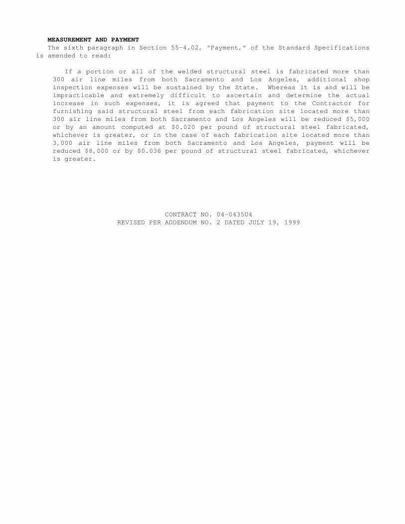
MEASUREMENT AND PAYMENT The sixth paragraph in Section 55-4.02, "Payment," of the Standard Specifications
is amended to read:
If a portion or all of the welded structural steel is fabricated more than 300 air line miles from both Sacramento and Los Angeles, additional shop inspection expenses will be sustained by the State. Whereas it is and will be impracticable and extremely difficult to ascertain and determine the actual increase in such expenses, it is agreed that payment to the Contractor for furnishing said structural steel from each fabrication site located more than 300 air line miles from both Sacramento and Los Angeles will be reduced $5,000 or by an amount computed at $0.020 per pound of structural steel fabricated, whichever is greater, or in the case of each fabrication site located more than 3,000 air line miles from both Sacramento and Los Angeles, payment will be reduced $8,000 or by $0.036 per pound of structural steel fabricated, whichever is greater.
CONTRACT NO. 04-0435U4 REVISED PER ADDENDUM NO. 2 DATED JULY 19, 1999
Pay quantities for structural steel will be measured and paid with deductions for perforations in structural steel plates.
If a portion of or all check samples are removed at a mill more than 300 air line miles from both Sacramento and Los Angeles, shop inspection expenses will be sustained by the State which are in addition to expenses incurred for fabrication site inspection. Payment to the Contractor for furnishing structural steel will be reduced $2,000 for each mill located more than 300 air line miles from both Sacramento and Los Angeles.
Full compensation for plate washers, erection bolts, drilling and coring existing steel, coring existing concrete, carbon equivalency testing repair methods and remedial work as required, shall be considered as included in the contract prices paid per pound for erect structural steel, bridge and no separate payment will be allowed therefor.

CONTRACT NO. 04-0435U4 REVISED PER ADDENDUM NO. 2 DATED JULY 19, 1999
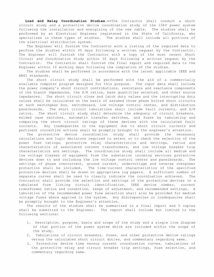
Load and Relay Coordination Studies.--The Contractor shall conduct a short circuit study and a protective device coordination study of the 15kV power system following the installation and energizing of the new cable. The studies shall be performed by an Electrical Engineer registered in the State of California, who specializes in these types of studies. The studies shall include all portions of the electrical distribution system.
The Engineer will furnish the Contractor with a listing of the required data to perform the studies within 30 days following a written request by the Contractor. The Engineer will furnish the Contractor with a copy of the most recent Short Circuit and Coordination Study within 30 days following a written request by the Contractor. The Contractor shall furnish the final report and required data to the Engineer within 10 working days following the completion of the studies.
The studies shall be performed in accordance with the latest applicable IEEE and ANSI standards.
The short circuit study shall be performed with the aid of a commercially available computer program designed for this purpose. The input data shall include the power company’s short circuit contributions, resistance and reactance components of the branch impedances, the X/R ratios, base quantities selected, and other source impedances. The short circuit close and latch duty values and the interrupting duty values shall be calculated on the basis of assumed three phase bolted short circuits at each switchgear bus, switchboard, low voltage control center, and distribution panelboards. The short circuit tabulations shall include fault currents, and X/R ratios. The short circuit study shall determine the adequacy of circuit breakers, molded case switches, automatic transfer switches, and fuses by tabulating and comparing the short circuit ratings of these devices with the calculated fault currents. Any inadequacies in the equipment due to short circuit currents and pertinent corrective actions shall be promptly brought to the engineer’s attention.
The protective device coordination study shall provide the necessary calculations and logic decisions required to select or to check the selection of the power fuse ratings, protective relay characteristics and settings, ratios and characteristics of associated current transformers, and low voltage breaker trip characteristics and settings. The coordination study shall include all medium and low voltage classes of equipment from the substation incoming services protective devices down to and including the low voltage control center and panelboards. The settings of phase overcurrent, ground current, undervoltage and reverse overpower protection shall be included. The time-current characteristics of the specified protective devices shall be drawn on appropriate log papers. A sufficient number of separate curves shall be used to clearly indicate the coordination achieved. The Contractor shall provide the selection and settings of the protective devices in a tabulated form listing circuit identification, IEEE device number, current transformer ratios and connection, range of adjustment, and recommended settings. A tabulation of the recommended power fuse selection shall also be provided for medium voltage fuses where applied in the system. Any discrepancies or inadequacies shall be promptly brought to the Engineer’s attention.
The results of the studies shall be summarized in a final report and 5 copies shall be submitted to the Engineer. The report shall include but limited to the following sections:
1. Description, purpose, basis and scope of the study and a single line diagram of that portion of the power system which are included within the scope of the study.
2. Tabulations of circuit breakers, fuses, and other protective device ratings versus the calculated short circuit duties, and commentary regarding same.
3. Protective device time versus current coordination curves, tabulations of the protective relay and circuit breaker trip settings, fuse selection, and commentary regarding same.
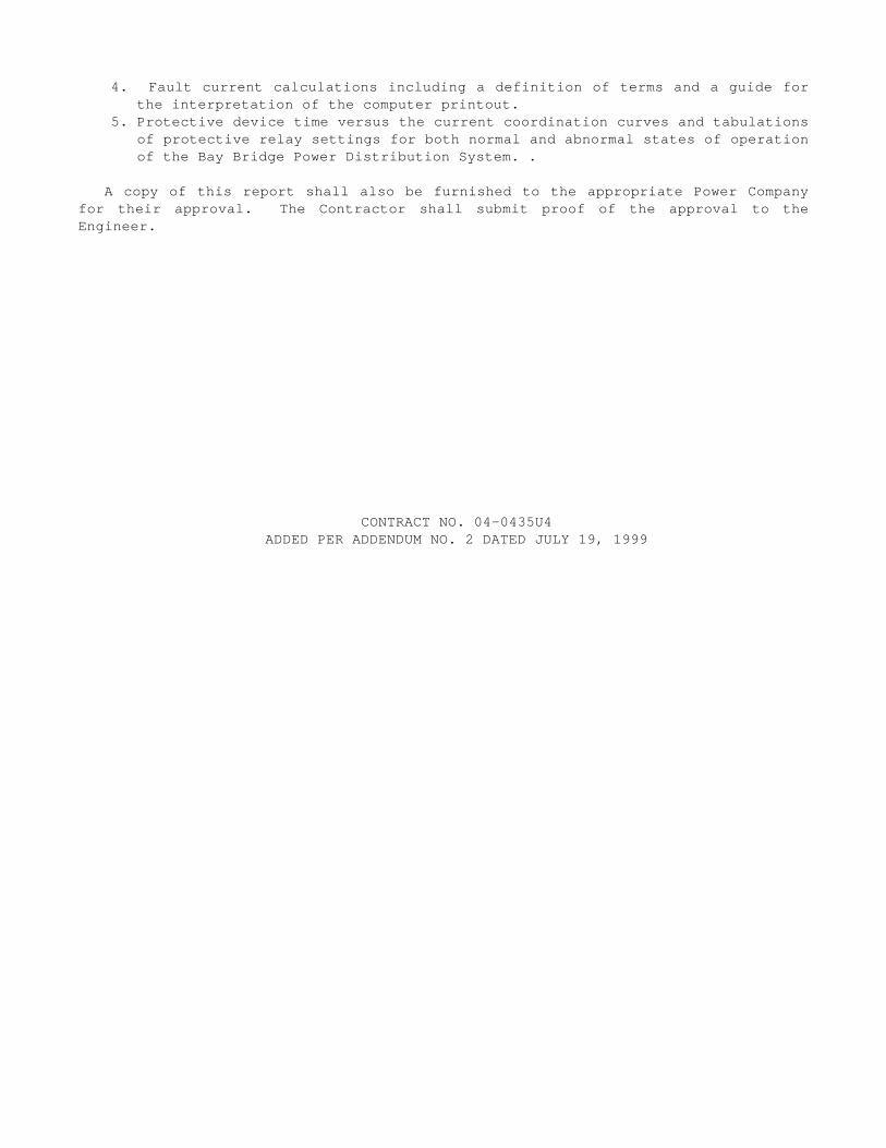
4. Fault current calculations including a definition of terms and a guide for the interpretation of the computer printout.
5. Protective device time versus the current coordination curves and tabulations of protective relay settings for both normal and abnormal states of operation of the Bay Bridge Power Distribution System. .
A copy of this report shall also be furnished to the appropriate Power Company for their approval. The Contractor shall submit proof of the approval to the Engineer.
CONTRACT NO. 04-0435U4 ADDED PER ADDENDUM NO. 2 DATED JULY 19, 1999
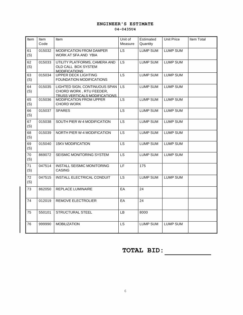
ENGINEER'S ESTIMATE 04-0435U4
Item Item Code
Item Unit of Measure
Estimated Quantity
Unit Price Item Total
61 (S)
015032 MODIFICATION FROM DAMPER WORK AT SFA AND YBIA
LS LUMP SUM LUMP SUM
62 (S)
015033 UTILITY PLATFORMS, CAMERA AND OLD CALL BOX SYSTEM MODIFICATIONS
LS LUMP SUM LUMP SUM
63 (S)
015034 UPPER DECK LIGHTING FOUNDATION MODIFICATIONS
LS LUMP SUM LUMP SUM
64 (S)
015035 LIGHTED SIGN, CONTINUOUS SPAN CHORD WORK , RTU FEEDER, TRUSS VERTICALS MODIFICATIONS
LS LUMP SUM LUMP SUM
65 (S)
015036 MODIFICATION FROM UPPER CHORD WORK
LS LUMP SUM LUMP SUM
66 (S)
015037 SPARES LS LUMP SUM LUMP SUM
67 (S)
015038 SOUTH PIER W-4 MODIFICATION LS LUMP SUM LUMP SUM
68 (S)
015039 NORTH PIER W-4 MODIFICATION LS LUMP SUM LUMP SUM
69 (S)
015040 15KV MODIFICATION LS LUMP SUM LUMP SUM
70 (S)
869072 SEISMIC MONITORING SYSTEM LS LUMP SUM LUMP SUM
71 (S)
047514 INSTALL SEISMIC MONITORING CASING
LF 175
72 (S)
047515 INSTALL ELECTRICAL CONDUIT LS LUMP SUM LUMP SUM
73 862050 REPLACE LUMINAIRE EA 24
74 012019 REMOVE ELECTROLIER EA 24
75 550101 STRUCTURAL STEEL LB 8000
76 999990 MOBILIZATION LS LUMP SUM LUMP SUM
TOTAL BID:
6

REVISED PER ADDENDUM NO. 2 DATED JULY 19, 1999


![Untitled-1 [preformed.com]preformed.com/images/pdfs/Communications/Fiber_Networks/...Buffer Tube Retainer Clips Shell Supporters (not shown) Splice Tray Splice Retainer Block Splice](https://img.dokumen.tips/doc/110x75/60ec7b50d1427246717b3904/untitled-1-buffer-tube-retainer-clips-shell-supporters-not-shown-splice.jpg)