Embed Size (px)
Citation preview
State of CaliforniaAIR RESOURCES BOARD
Executive Order G-70-187
Certification of the Healy Model 400 ORVRVapor Recovery System for Aboveground
Storage Tank Systems
WHEREAS, the California Air Resources Board ("the Board" or "CARB") has established, pursuantto California Health and Safety Code sections 39600, 39601 and 41954, certification procedures forsystems designed for the control of gasoline vapor emissions during motor vehicle fueling operations(Phase II vapor recovery systems) in its "CP-205 Certification Procedure for Vapor RecoverySystems of Novel Facilities" (the "Certification Procedures") as last amended March 17,1999,incorporated by reference into Title 17, California Code of Regulations, Section 94015;
WHEREAS, the Board has established, pursuant to California Health and Safety Code sections39600, 39601 and 41954, test procedures for determining the compliance of Phase II vapor recoverysystems with emission standards in its "Determination of Efficiency of Phase II Vapor RecoverySystems of Novel Facilities", TP-205.2 ("the Test Procedures") as last amended March 17, 1999,incorporated by reference into Title 17, California Code of Regulations, Section 94015;
WHEREAS, James W. Healy of Healy Systems, Incorporated ("Healy") has requested certificationof the Healy Model 400 ORVR Nozzle with central vacuum sources for previously certified integralaboveground storage tank systems pursuant to the Certification Procedures and Test Procedures;
WHEREAS, the Executive Officer has determined, pursuant to Section 3.1 of the CertificationProcedures, that components used in installations of the Healy 400 ORVR System for abovegroundstorage tank systems must meet the same performance standards and specifications met duringcertification under CP-201, “Certification Procedure for Vapor Recovery Systems of DispensingFacilities”;
WHEREAS, the Healy Model 400 ORVR Vapor Recovery System (the vapor recovery system) hasbeen evaluated pursuant to the Board's Certification Procedures;
WHEREAS, Section 7 of the Certification Procedures provides that the Executive Officer shall issuean order of certification if he or she determines that the vapor recovery system conforms to all of therequirements set forth in Section 1 through 6 of the Certification Procedures;
WHEREAS, the Executive Officer acknowledges the need for the introduction of vapor recoverysystems that are compatible with, and efficient when refueling vehicles having an onboard refuelingvapor recovery system (ORVR vehicles); and
WHEREAS, I, Michael P. Kenny, Air Resources Board Executive Officer, find that the Healy Model400 ORVR Vapor Recovery System conforms with all the requirements set forth in the Certification
Executive Order G-70-187 Page 2
Procedures and results in a vapor recovery system which is at least 95 percent effective for attendantand/or self-serve use at gasoline service stations or remote locations when used in conjunction witha previously certified integral aboveground storage tank Phase I vapor recovery system and meetingthe requirements contained in Exhibit 2 of this Order.
WHEREAS, Sections 3.4.1, 5.4 and 7 of CP-201 provide that the Executive Officer may conditionthe certification of any system;
NOW, THEREFORE, IT IS HEREBY ORDERED that Healy Model 400 ORVR System is certifiedto be at least 95 percent effective in attended and/or self-service mode when used with a previouslycertified single or split product integral aboveground storage tank Phase I vapor recovery system andwhich meets the requirements as specified in Exhibits 1 and 2. Fugitive emissions, which may occurwhen the aboveground storage tanks are under positive pressure have not been quantified and werenot included in the calculation of system effectiveness. Preliminary compatibility of this systemwith onboard vapor refueling vapor recovery (ORVR) systems has been determined. Thissystem passed evaluation of refueling ORVR-equipped vehicles. Exhibit 1 contains a list of theequipment certified for use with the Healy Model 400 ORVR System. Exhibit 2 contains installationand performance specifications for the system. Exhibit 3 contains a static pressure decay test for thePhase 1 system and vent piping. Exhibit 4 contains a static pressure decay test specifically for thePhase II piping network between the nozzle and the Healy Central Vacuum Unit. Exhibit 5 containsthe Fillneck Vapor Pressure Regulation Fueling Test for the Healy Model 400 ORVR nozzle. Exhibit6 contains the ten-gallon per minute maximum fueling rate compliance verification procedure.
IT IS FURTHER ORDERED that the following requirements are made a condition of certification.The Healy Model 400 ORVR System shall be installed only in facilities which are capable ofdemonstrating ongoing compliance with the vapor integrity requirements contained in Exhibit 3 (Static Pressure Decay Test), Exhibit 4 (Vapor Return Line Vacuum Integrity Test) and Exhibit 5(Vapor Pressure Regulation Test). The owner or operator of the installation shall conduct, and pass,the specified tests no later than 60 calendar days after startup and at least once in each twelve monthperiod. The test results shall be made available to the local air pollution control or air qualitymanagement district upon request within fifteen calendar days after the tests are conducted. Testresults shall be submitted to the district in the format specified by the district.
IT IS FURTHER ORDERED that the Healy Model 400 ORVR System, as installed, shall complywith the procedures and performance standards the test installation was required to meet duringcertification testing. If, in the judgment of the Executive Officer, a significant fraction of theinstallations fails to meet the specifications of this certification, or if a significant portion of the vehiclepopulation is found to have configurations which significantly impair the system's collectionefficiency, the certification itself may be subject to modification, suspension or revocation.
IT IS FURTHER ORDERED that compliance with the certification requirements and rules andregulations of the Division of Measurement Standards of the Department of Food and Agriculture,the State Fire Marshal's Office, and the Division of Occupational Safety and Health of the Departmentof Industrial Relations are made a condition of this certification.

Executive Order G-70-187 Page 3
IT IS FURTHER ORDERED that the Healy Model 400 ORVR System shall, at a minimum, beoperated in accordance with the manufacturer's recommended maintenance intervals and shall use themanufacturer's recommended operation and maintenance procedures as approved by CARB. Revisions to the manufacturers’ manuals shall be approved by CARB. The Executive Officer mayadd or delete instructions from the manuals and distribute revised copies in accordance with CP-201.
IT IS FURTHER ORDERED that Healy Model 400 ORVR System installations shall have a CARB-certified System monitor as specified in Exhibit 2 except when the monthly throughput is less than10,000 gallons.
IT IS FURTHER ORDERED that Healy Systems shall provide, to the station or facility owner,operator or designee, CARB-approved copies of the operation and maintenance manuals for theHealy Model 400 ORVR System. Healy Systems or a factory authorized representative, shall provideto the station manager or other responsible individual, instructions in the proper use of the HealyModel 400 ORVR System, its repair and maintenance schedules, and locations where system and/orcomponent replacements can be readily obtained. Revisions to the manual are subject to approval byCARB. The Executive Officer may add or delete instructions from the manuals and distribute revisedcopies in accordance with CP-201.
IT IS FURTHER ORDERED that copies of this Executive Order and installation and maintenancemanuals for the Healy Model 400 ORVR System shall be stored at the facility for service station typeoperations or at a central location for remote or unattended locations.
IT IS FURTHER ORDERED that Healy Systems shall warranty the Healy Model 400 ORVR Systemfor at least one year, in writing, to the ultimate purchaser and each subsequent purchaser, that thevapor recovery system is designed, built and equipped so as to conform, at the time of originalinstallation or sale, with the applicable regulations and is free from defects in materials andworkmanship which would cause the vapor recovery system to fail to conform with applicableregulations. Healy Systems shall provide copies of the manufacturer's warranty for the Healy Model400 ORVR System, to the station manager, owner or operator. Hoses, nozzles and breakawaycouplings shall be warranted to the ultimate purchaser as specified above for at least one year, or forthe expected useful life, whichever is longer.
IT IS FURTHER ORDERED that any alteration of the equipment, parts, design, or operation of thesystem certified hereby is prohibited unless such alteration has been approved by the ExecutiveOfficer or his or her designee. Any unapproved alteration shall void the certification for the specificinstallation where such alteration occurred.
Executed at Sacramento, California, this _________ day of _________________, 1999.
signed September 13, 1999 Michael P. KennyExecutive Officer
Executive Order G-70-187
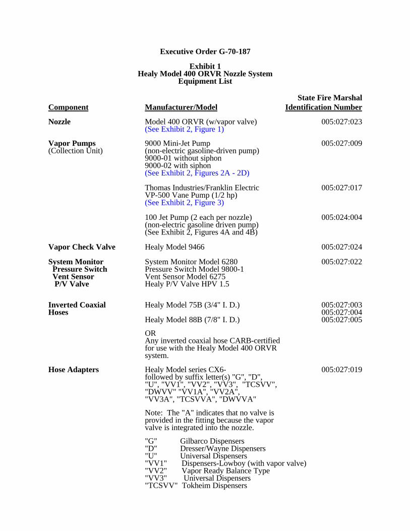
Exhibit 1Healy Model 400 ORVR Nozzle System
Equipment List
State Fire MarshalComponent Manufacturer/Model Identification Number
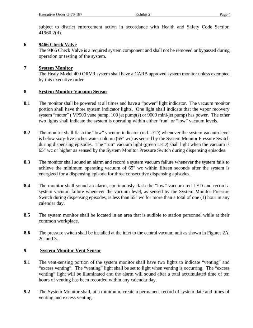
Nozzle Model 400 ORVR (w/vapor valve) 005:027:023(See Exhibit 2, Figure 1)
Vapor Pumps 9000 Mini-Jet Pump 005:027:009(Collection Unit) (non-electric gasoline-driven pump)
9000-01 without siphon9000-02 with siphon(See Exhibit 2, Figures 2A - 2D)
Thomas Industries/Franklin Electric 005:027:017VP-500 Vane Pump (1/2 hp)(See Exhibit 2, Figure 3)
100 Jet Pump (2 each per nozzle) 005:024:004(non-electric gasoline driven pump)(See Exhibit 2, Figures 4A and 4B)
Vapor Check Valve Healy Model 9466 005:027:024
System Monitor System Monitor Model 6280 005:027:022 Pressure Switch Pressure Switch Model 9800-1 Vent Sensor Vent Sensor Model 6275 P/V Valve Healy P/V Valve HPV 1.5
Inverted Coaxial Healy Model 75B (3/4" I. D.) 005:027:003Hoses 005:027:004
Healy Model 88B (7/8" I. D.) 005:027:005
ORAny inverted coaxial hose CARB-certifiedfor use with the Healy Model 400 ORVRsystem.
Hose Adapters Healy Model series CX6- 005:027:019followed by suffix letter(s) "G", "D","U", "VV1", "VV2", "VV3", "TCSVV","DWVV" "VV1A", "VV2A","VV3A", "TCSVVA", "DWVVA"
Note: The "A" indicates that no valve isprovided in the fitting because the vaporvalve is integrated into the nozzle.
"G" Gilbarco Dispensers"D" Dresser/Wayne Dispensers"U" Universal Dispensers"VV1" Dispensers-Lowboy (with vapor valve)"VV2" Vapor Ready Balance Type"VV3" Universal Dispensers"TCSVV" Tokheim Dispensers
Executive Order G-70-187 Exhibit 1 Page 2
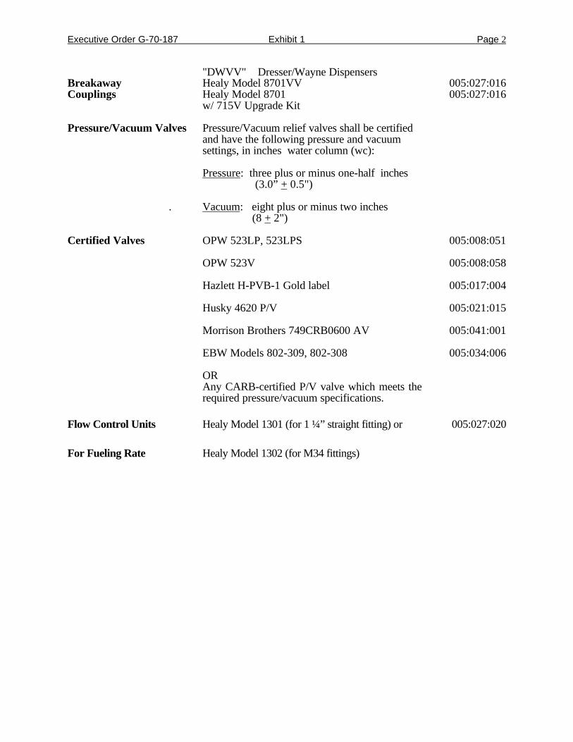
"DWVV" Dresser/Wayne DispensersBreakaway Healy Model 8701VV 005:027:016Couplings Healy Model 8701 005:027:016
w/ 715V Upgrade Kit
Pressure/Vacuum Valves Pressure/Vacuum relief valves shall be certifiedand have the following pressure and vacuumsettings, in inches water column (wc):
Pressure: three plus or minus one-half inches (3.0” + 0.5")
. Vacuum: eight plus or minus two inches (8 + 2")
Certified Valves OPW 523LP, 523LPS 005:008:051
OPW 523V 005:008:058
Hazlett H-PVB-1 Gold label 005:017:004
Husky 4620 P/V 005:021:015
Morrison Brothers 749CRB0600 AV 005:041:001
EBW Models 802-309, 802-308 005:034:006
ORAny CARB-certified P/V valve which meets therequired pressure/vacuum specifications.
Flow Control Units Healy Model 1301 (for 1 ¼” straight fitting) or 005:027:020
For Fueling Rate Healy Model 1302 (for M34 fittings)
Executive Order G-70-187
Exhibit 2
Specifications for the Healy Model 400 ORVR Vapor Recovery System for Aboveground Storage Tank Systems
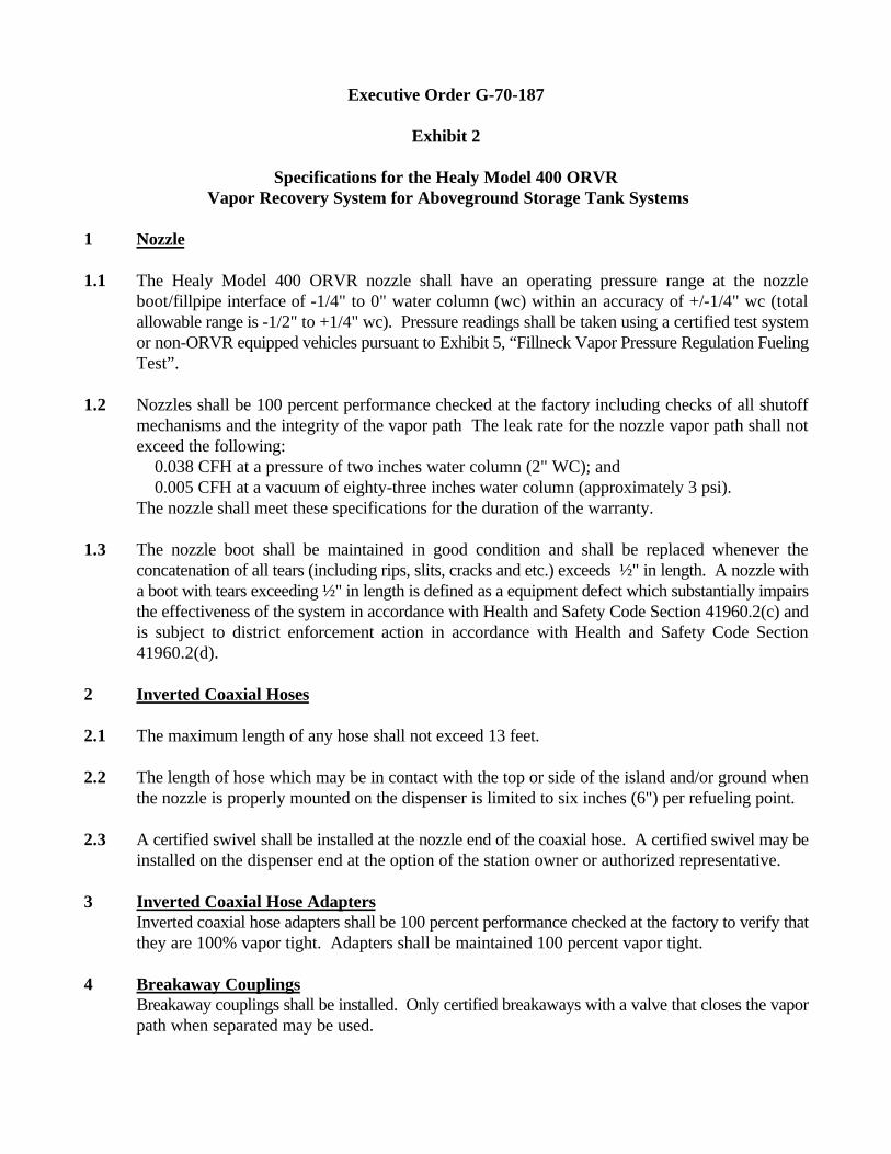
1 Nozzle
1.1 The Healy Model 400 ORVR nozzle shall have an operating pressure range at the nozzleboot/fillpipe interface of -1/4" to 0" water column (wc) within an accuracy of +/-1/4" wc (totalallowable range is -1/2" to +1/4" wc). Pressure readings shall be taken using a certified test systemor non-ORVR equipped vehicles pursuant to Exhibit 5, “Fillneck Vapor Pressure Regulation FuelingTest”.
1.2 Nozzles shall be 100 percent performance checked at the factory including checks of all shutoffmechanisms and the integrity of the vapor path The leak rate for the nozzle vapor path shall notexceed the following: 0.038 CFH at a pressure of two inches water column (2" WC); and 0.005 CFH at a vacuum of eighty-three inches water column (approximately 3 psi).The nozzle shall meet these specifications for the duration of the warranty.
1.3 The nozzle boot shall be maintained in good condition and shall be replaced whenever theconcatenation of all tears (including rips, slits, cracks and etc.) exceeds ½" in length. A nozzle witha boot with tears exceeding ½" in length is defined as a equipment defect which substantially impairsthe effectiveness of the system in accordance with Health and Safety Code Section 41960.2(c) andis subject to district enforcement action in accordance with Health and Safety Code Section41960.2(d).
2 Inverted Coaxial Hoses
2.1 The maximum length of any hose shall not exceed 13 feet.
2.2 The length of hose which may be in contact with the top or side of the island and/or ground whenthe nozzle is properly mounted on the dispenser is limited to six inches (6") per refueling point.
2.3 A certified swivel shall be installed at the nozzle end of the coaxial hose. A certified swivel may beinstalled on the dispenser end at the option of the station owner or authorized representative.
3 Inverted Coaxial Hose AdaptersInverted coaxial hose adapters shall be 100 percent performance checked at the factory to verify thatthey are 100% vapor tight. Adapters shall be maintained 100 percent vapor tight.
4 Breakaway CouplingsBreakaway couplings shall be installed. Only certified breakaways with a valve that closes the vaporpath when separated may be used.
Executive Order G-70-187 Exhibit 2 Page 2
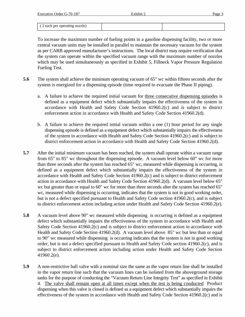
5 Central Vacuum Unit
5.1 The Healy Model 400 ORVR system shall operate with at least one of the central vacuum units(pumps) specified in Exhibit 1 (see Figures 2A-2D and Figure 3). Each central vacuum pump shallbe 100 percent performance checked at the factory including verification that the pump, wheninstalled in the system, can be adjusted such that the vapor recovery system performance willoperate within the range specified in Exhibit 2 of this executive order. The vapor recovery systemvacuum shall be checked and the central vacuum unit adjusted (if necessary) after installation andbefore commencing operation of the system to insure that the system vacuum operates within adynamic range from 65" wc to 85" wc.
5.2 No dispensing shall be allowed when the central vacuum unit is disabled for maintenance or for anyother reason. Dispensing of gasoline when the central vacuum unit is disabled is defined as aequipment defect which substantially impairs the effectiveness of the system in accordance withHealth and Safety Code Section 41960.2(c) and is subject to district enforcement action inaccordance with Health and Safety Code Section 41960.2(d).
5.3 The system shall be equipped with a vacuum gauge (0"- 100" wc) in order to manually monitor thesystem vacuum. The gauge shall be installed on the inlet side of the central vacuum unit (seeFigures 2A, 2C, 3 and 4A) by means of a “tee” and two ball valves with (1) one end of the “tee”connected directly to the gauge, (2) the second end of the “tee” connected to the first ball valvewhich is connected to the vacuum line and (3) the middle of the “tee” connected to the second ballvalve which opens to atmosphere. Both valves shall be closed and the atmospheric port cappedexcept when the gauge is in use. The atmospheric valve may be opened with the vacuum valveclosed in order to check the gauge “zero”; a second gauge may also be connected to theatmospheric port with the ball valve to the system vacuum open to check the gauge accuracy.
5.4 The system shall operate within a vacuum range from 65" to 85" wc. This vacuum range shall bedetermined by observing the mechanical gauge as required by Section 5.3.
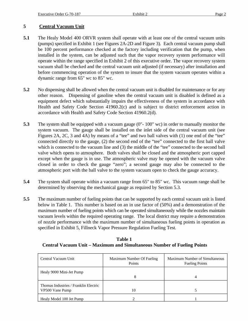
5.5 The maximum number of fueling points that can be supported by each central vacuum unit is listedbelow in Table 1. This number is based on an in use factor of (50%) and a demonstration of themaximum number of fueling points which can be operated simultaneously while the nozzles maintainvacuum levels within the required operating range. The local district may require a demonstrationof nozzle performance with the maximum number of simultaneous fueling points in operation asspecified in Exhibit 5, Fillneck Vapor Pressure Regulation Fueling Test.
Table 1 Central Vacuum Unit – Maximum and Simultaneous Number of Fueling Points
Central Vacuum Unit Maximum Number Of FuelingPoints
Maximum Number of SimultaneousFueling Points
Healy 9000 Mini-Jet Pump 8 4
Thomas Industries / Franklin ElectricVP500 Vane Pump 10 5
Healy Model 100 Jet Pump 2 1
Executive Order G-70-187 Exhibit 2 Page 3
( 2 each per operating nozzle)
To increase the maximum number of fueling points in a gasoline dispensing facility, two or morecentral vacuum units may be installed in parallel to maintain the necessary vacuum for the systemas per CARB approved manufacturer’s instructions. The local district may require verification thatthe system can operate within the specified vacuum range with the maximum number of nozzleswhich may be used simultaneously as specified in Exhibit 5, Fillneck Vapor Pressure RegulationFueling Test.
5.6 The system shall achieve the minimum operating vacuum of 65" wc within fifteen seconds after thesystem is energized for a dispensing episode (time required to evacuate the Phase II piping).
a. A failure to achieve the required initial vacuum for three consecutive dispensing episodes isdefined as a equipment defect which substantially impairs the effectiveness of the system inaccordance with Health and Safety Code Section 41960.2(c) and is subject to districtenforcement action in accordance with Health and Safety Code Section 41960.2(d).
b. A failure to achieve the required initial vacuum within a one (1) hour period for any singledispensing episode is defined as a equipment defect which substantially impairs the effectivenessof the system in accordance with Health and Safety Code Section 41960.2(c) and is subject todistrict enforcement action in accordance with Health and Safety Code Section 41960.2(d).
5.7 After the initial minimum vacuum has been reached, the system shall operate within a vacuum rangefrom 65" to 85" wc throughout the dispensing episode. A vacuum level below 60" wc for morethan three seconds after the system has reached 65" wc, measured while dispensing is occurring, isdefined as a equipment defect which substantially impairs the effectiveness of the system inaccordance with Health and Safety Code Section 41960.2(c) and is subject to district enforcementaction in accordance with Health and Safety Code Section 41960.2(d). A vacuum level below 65"wc but greater than or equal to 60" wc for more than three seconds after the system has reached 65"wc, measured while dispensing is occurring, indicates that the system is not in good working order,but is not a defect specified pursuant to Health and Safety Code section 41960.2(c), and is subjectto district enforcement action including action under Health and Safety Code Section 41960.2(e).
5.8 A vacuum level above 90" wc measured while dispensing is occurring is defined as a equipmentdefect which substantially impairs the effectiveness of the system in accordance with Health andSafety Code Section 41960.2(c) and is subject to district enforcement action in accordance withHealth and Safety Code Section 41960.2(d). A vacuum level above 85" wc but less than or equalto 90" wc measured while dispensing is occurring indicates that the system is not in good workingorder, but is not a defect specified pursuant to Health and Safety Code section 41960.2(c), and issubject to district enforcement action including action under Health and Safety Code Section41960.2(e).
5.9 A non-restrictive ball valve with a nominal size the same as the vapor return line shall be installedin the vapor return line such that the vacuum lines can be isolated from the aboveground storagetanks for the purpose of conducting the “Vacuum Return Line Integrity Test” as specified in Exhibit4. The valve shall remain open at all times except when the test is being conducted Productdispensing when this valve is closed is defined as a equipment defect which substantially impairs theeffectiveness of the system in accordance with Health and Safety Code Section 41960.2(c) and is
Executive Order G-70-187 Exhibit 2 Page 4
subject to district enforcement action in accordance with Health and Safety Code Section41960.2(d).
6 9466 Check ValveThe 9466 Check Valve is a required system component and shall not be removed or bypassed duringoperation or testing of the system.
7 System MonitorThe Healy Model 400 ORVR system shall have a CARB approved system monitor unless exemptedby this executive order.
8 System Monitor Vacuum Sensor
8.1 The monitor shall be powered at all times and have a “power” light indicator. The vacuum monitorportion shall have three system indicator lights. One light shall indicate that the vapor recoverysystem “motor” ( VP500 vane pump, 100 jet pump(s) or 9000 mini-jet pump) has power. The othertwo lights shall indicate the system is operating within either “run” or “low” vacuum levels.
8.2 The monitor shall flash the “low” vacuum indicator (red LED) whenever the system vacuum levelis below sixty-five inches water column (65" wc) as sensed by the System Monitor Pressure Switchduring dispensing episodes. The “run” vacuum light (green LED) shall light when the vacuum is65" wc or higher as sensed by the System Monitor Pressure Switch during dispensing episodes.
8.3 The monitor shall sound an alarm and record a system vacuum failure whenever the system fails toachieve the minimum operating vacuum of 65" wc within fifteen seconds after the system isenergized for a dispensing episode for three consecutive dispensing episodes.
8.4 The monitor shall sound an alarm, continuously flash the “low” vacuum red LED and record asystem vacuum failure whenever the vacuum level, as sensed by the System Monitor PressureSwitch during dispensing episodes, is less than 65" wc for more than a total of one (1) hour in anycalendar day.
8.5 The system monitor shall be located in an area that is audible to station personnel while at theircommon workplace.
8.6 The pressure switch shall be installed at the inlet to the central vacuum unit as shown in Figures 2A,2C and 3.
9 System Monitor Vent Sensor
9.1 The vent-sensing portion of the system monitor shall have two lights to indicate “venting” and“excess venting”. The “venting” light shall be set to light when venting is occurring. The “excessventing” light will be illuminated and the alarm will sound after a total accumulated time of tenhours of venting has been recorded within any calendar day.
9.2 The System Monitor shall, at a minimum, create a permanent record of system date and times ofventing and excess venting.
Executive Order G-70-187 Exhibit 2 Page 5
10 Log Requirements
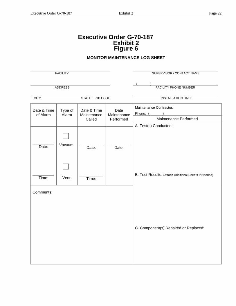
10.1 The Monitor shall cause a continuous audible alarm as specified in Sections 8.4, 8.7 and 9.1. Thealarm may be silenced for a four hour period with a reset button but shall resound if the conditionwhich caused the alarm is still present. The station owner/operator shall call for maintenance within24 hours of the initial alarm sounding and shall maintain a “Monitor Maintenance Log Sheet” (seeFigure 6) of all alarm events and corresponding maintenance actions. This log shall be kept on siteat all times for service station type operations and at a central location for remote or unattendedoperations.
10.2 The owner/operator of service station type systems shall conduct a physical inspection of theequipment on a daily basis and manually monitor the system vacuum levels at the system vacuumgauge on a once per day basis during a dispensing episode to determine proper operation of thesystem. The inspection results and vacuum observations shall be recorded in a System Log to bekept on site at all times for service station type operations and at a central location for remote orunattended operations.
.
11 Phase II Vapor Recovery System
11.1 Operation of the Phase II system shall not cause venting through the system monitor vent in excessof ten (10) hours in any calendar day. Any venting through the system monitor vent in excess often (10) hours in any calendar day which is not attributable to a Phase I fuel delivery is subject todistrict enforcement action in accordance with Health and Safety Code Section 41960.2(e). Ventingthrough the system monitor vent may be attributed to a Phase I delivery for the duration of thedelivery and for a maximum one (1) period following the delivery. The station owner / operator willrecord events of venting which may be attributed to a Phase I fuel delivery in the System Log. Venting through the 3” pressure setting relief vent is defined as a equipment defect whichsubstantially impairs the effectiveness of the system in accordance with Health and Safety CodeSection 41960.2(c) and is subject to district enforcement action in accordance with Health andSafety Code Section 41960.2(d).
11.2 The minimum nominal pipe size of the Phase II plumbing shall be 2" up to the riser to theaboveground storage tank where the minimum nominal pipe size shall be 1". This requirement doesnot apply to self-contained dispenser pump systems as shown in Figure 4A.
11.3 The dispenser-to-riser connection shall be installed so that any liquid in the lines will drain towardthe Phase II line low point. The internal diameter of the connector, including all fittings, shall notbe less than five-eighths inch (5/8") for new factory equipped dispensers. The Healy Model seriesZ0XXX vapor recovery retrofit kits (which consist of two 0.5" OD copper tube and flare fittingsto connect all hose outlet fittings on one side of the dispenser to a 2" pipe running vertically fromthe canopy to the base of the dispenser where 0.5" OD copper tubing and flare fittings connect tothe underground vapor return riser) may be used on existing dispensers. This piping configurationis required on each side of the dispenser.
11.4 All vapor return lines shall have a slope sufficient to prevent a liquid blockage when used inconjunction with a low point condensate trap or knockout pot.
Executive Order G-70-187 Exhibit 2 Page 6
11.5 A condensate trap or knockout pot with an automatic liquid removal system shall be installed at thelow point in the vapor return piping (see Figures 2B, 2D and 4D).
11.6 All exposed Phase II piping shall be painted white or off-white (with any color base) provided thereflectivity of the paint is 75 percent or better. Reflectivity shall be determined by visual comparisonof the paint with paint color cards obtained from a paint manufacturer who uses the “Master PalletNotation” to specify the paint color (i.e. 58YY 88/180 where the number in italics is the paintreflectivity). The appropriate color card shall be available at the facility for service station typeoperations or at a central location for remote or unattended locations.
12 Phase I System
12.1 The Phase I system shall be a CARB-certified system which is in good working order and whichdemonstrates compliance with the static pressure decay test criteria contained in Exhibit 3.
12.2 Spill containment boxes (when present) that have drain valves shall demonstrate compliance withthe static pressure decay criteria with the drain valves installed as in normal operation.
12.3 The Phase I vapor recovery system shall be operated during product deliveries with no less than onevapor return hose connected for each product being delivered
12.4 All Phase I adapters, fittings and connections shall be maintained vapor tight as defined in CARBSource Test Methods Volume 2, Vapor Recovery Definitions, D-200.
12.5 The installation of the tank and associated piping and other equipment not specifically listed ascertified Phase I equipment in CARB executive orders shall comply with the requirements of localfire officials with jurisdiction where the system is installed.
13 Dispensing RateThe dispensing rate for installations of the Healy Model 400 ORVR System shall not exceed ten(10.0) gallons per minute for any nozzle. The dispensing rate shall be verified as specified in Exhibit6, “Ten Gallon Per Minute Limitation Compliance Verification Procedure”.
Healy 400 ORVR Nozzle
Executive Order G-70-187Exhibit 2Figure 1
Indicates ORVRnozzle
Executive Order G-70-187 Exhibit 2 Page 8
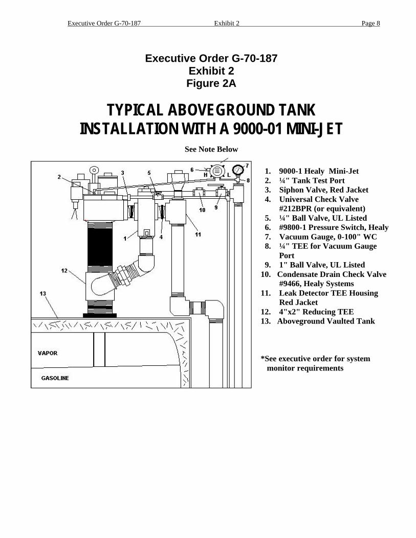
Executive Order G-70-187Exhibit 2Figure 2A
TYPICAL ABOVEGROUND TANKINSTALLATION WITH A 9000-01 MINI-JET
See Note Below
1. 9000-1 Healy Mini-Jet 2. ¼" Tank Test Port 3. Siphon Valve, Red Jacket 4. Universal Check Valve #212BPR (or equivalent) 5. ¼" Ball Valve, UL Listed 6. #9800-1 Pressure Switch, Healy 7. Vacuum Gauge, 0-100" WC 8. ¼" TEE for Vacuum Gauge Port 9. 1" Ball Valve, UL Listed10. Condensate Drain Check Valve #9466, Healy Systems11. Leak Detector TEE Housing Red Jacket12. 4"x2" Reducing TEE13. Aboveground Vaulted Tank
*See executive order for system monitor requirements
Executive Order G-70-187 Exhibit 2 Page 9
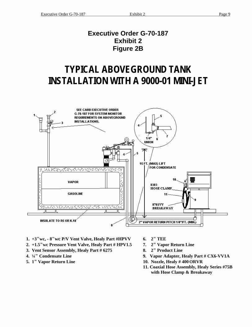
Executive Order G-70-187Exhibit 2Figure 2B
TYPICAL ABOVEGROUND TANKINSTALLATION WITH A 9000-01 MINI-JET
1. +3"wc, - 8"wc P/V Vent Valve, Healy Part #HPVV 6. 2" TEE2. +1.5"wc Pressure Vent Valve, Healy Part # HPV1.5 7. 2" Vapor Return Line3. Vent Sensor Assembly, Healy Part # 6275 8. 2" Product Line4. ¼" Condensate Line 9. Vapor Adapter, Healy Part # CX6-VV1A5. 1" Vapor Return Line 10. Nozzle, Healy # 400 ORVR
11. Coaxial Hose Assembly, Healy Series #75B with Hose Clamp & Breakaway
Executive Order G-70-187 Exhibit 2 Page 10
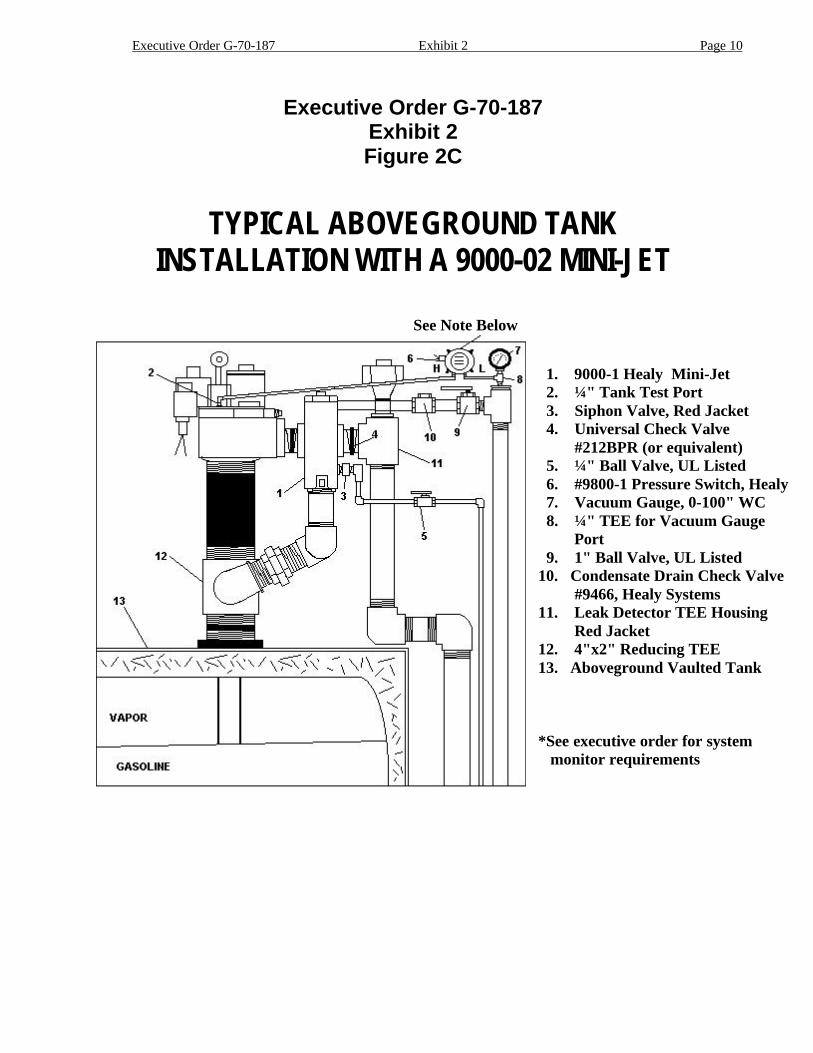
Executive Order G-70-187Exhibit 2Figure 2C
TYPICAL ABOVEGROUND TANKINSTALLATION WITH A 9000-02 MINI-JET
See Note Below
1. 9000-1 Healy Mini-Jet 2. ¼" Tank Test Port 3. Siphon Valve, Red Jacket 4. Universal Check Valve #212BPR (or equivalent) 5. ¼" Ball Valve, UL Listed 6. #9800-1 Pressure Switch, Healy 7. Vacuum Gauge, 0-100" WC 8. ¼" TEE for Vacuum Gauge Port 9. 1" Ball Valve, UL Listed10. Condensate Drain Check Valve #9466, Healy Systems11. Leak Detector TEE Housing Red Jacket12. 4"x2" Reducing TEE13. Aboveground Vaulted Tank
*See executive order for system monitor requirements
Executive Order G-70-187 Exhibit 2 Page 11
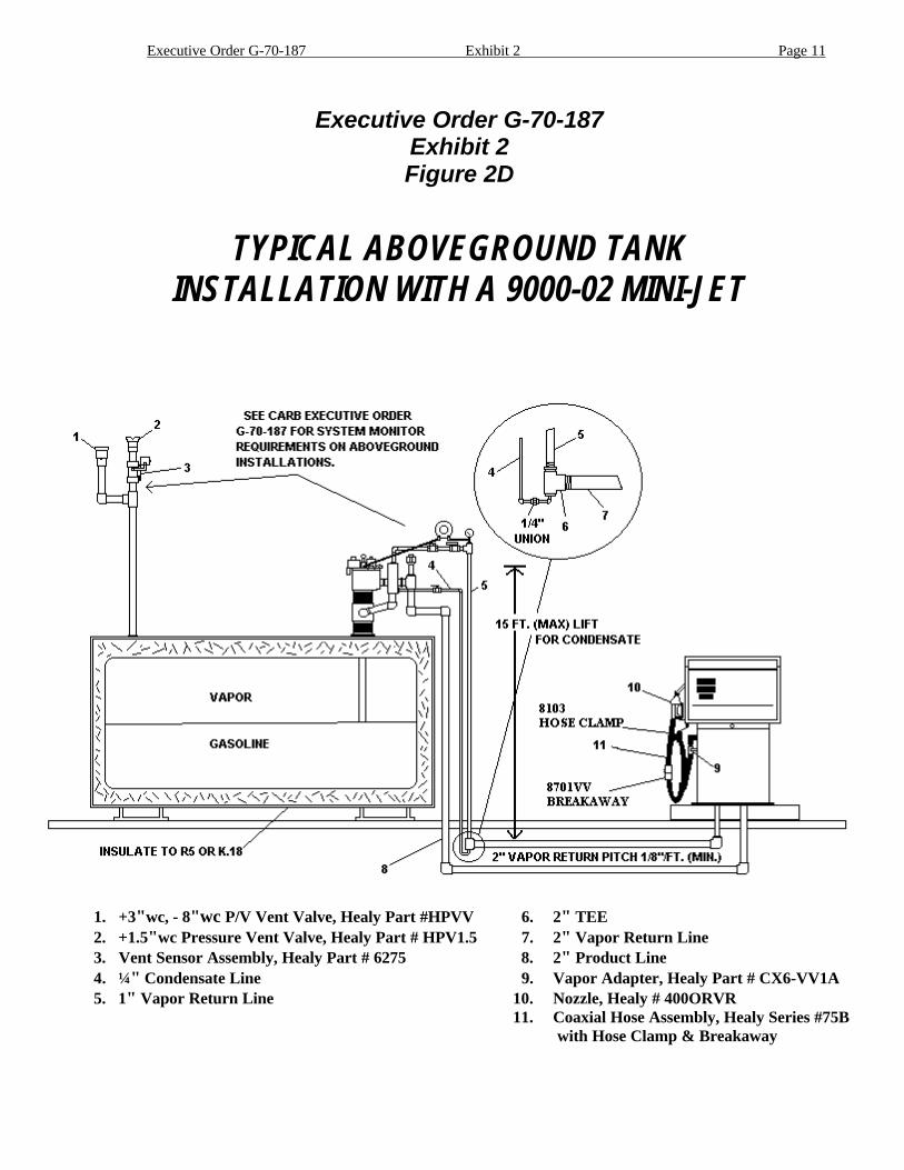
Executive Order G-70-187Exhibit 2Figure 2D
TYPICAL ABOVEGROUND TANKINSTALLATION WITH A 9000-02 MINI-JET
1. +3"wc, - 8"wc P/V Vent Valve, Healy Part #HPVV 6. 2" TEE2. +1.5"wc Pressure Vent Valve, Healy Part # HPV1.5 7. 2" Vapor Return Line3. Vent Sensor Assembly, Healy Part # 6275 8. 2" Product Line4. ¼" Condensate Line 9. Vapor Adapter, Healy Part # CX6-VV1A5. 1" Vapor Return Line 10. Nozzle, Healy # 400ORVR
11. Coaxial Hose Assembly, Healy Series #75B with Hose Clamp & Breakaway
Executive Order G-70-187 Exhibit 2 Page 12
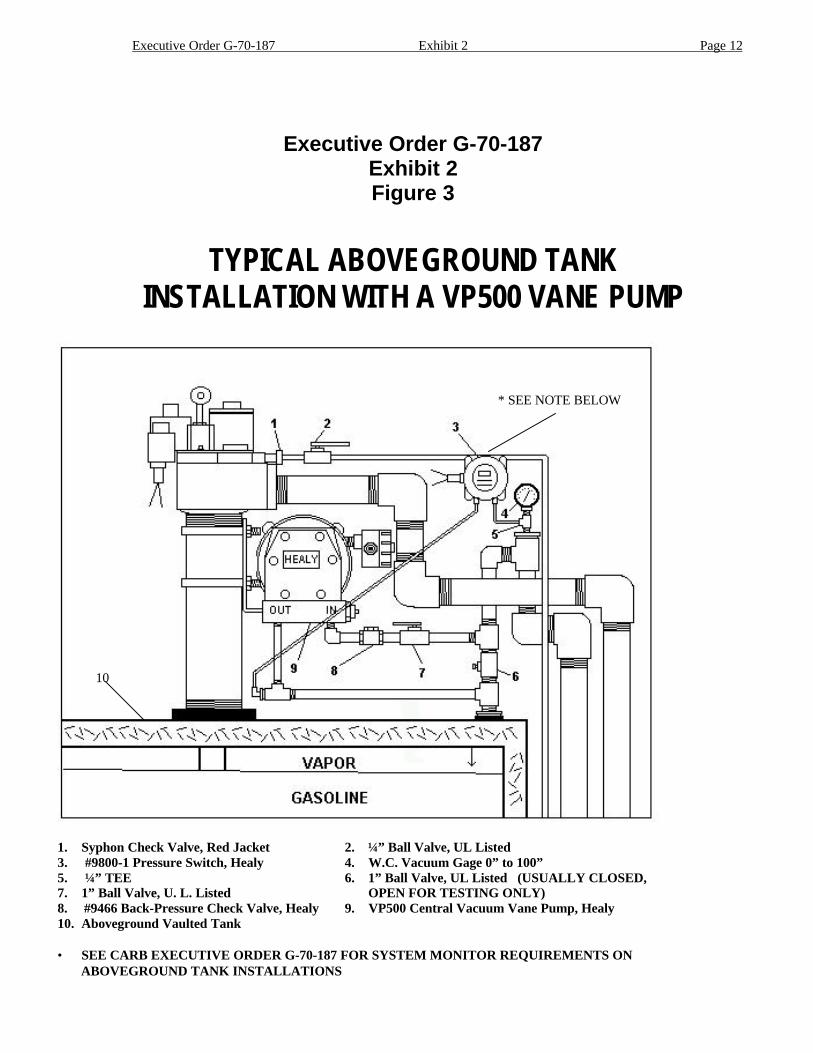
Executive Order G-70-187Exhibit 2Figure 3
TYPICAL ABOVEGROUND TANKINSTALLATION WITH A VP500 VANE PUMP
1. Syphon Check Valve, Red Jacket 2. ¼” Ball Valve, UL Listed3. #9800-1 Pressure Switch, Healy 4. W.C. Vacuum Gage 0” to 100”5. ¼” TEE 6. 1” Ball Valve, UL Listed (USUALLY CLOSED,7. 1” Ball Valve, U. L. Listed OPEN FOR TESTING ONLY)8. #9466 Back-Pressure Check Valve, Healy 9. VP500 Central Vacuum Vane Pump, Healy10. Aboveground Vaulted Tank
• SEE CARB EXECUTIVE ORDER G-70-187 FOR SYSTEM MONITOR REQUIREMENTS ON ABOVEGROUND TANK INSTALLATIONS
10
10
* SEE NOTE BELOW
Executive Order G-70-187 Exhibit 2 Page 13
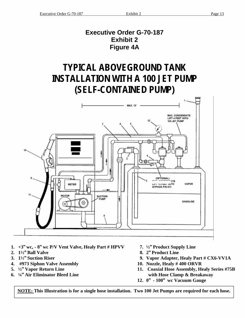
Executive Order G-70-187Exhibit 2Figure 4A
TYPICAL ABOVEGROUND TANKINSTALLATION WITH A 100 JET PUMP
(SELF-CONTAINED PUMP)
1. +3" wc, - 8" wc P/V Vent Valve, Healy Part # HPVV 7. ½" Product Supply Line2. 1½" Ball Valve 8. 2" Product Line3. 1½" Suction Riser 9. Vapor Adapter, Healy Part # CX6-VV1A4. #973 Siphon Valve Assembly 10. Nozzle, Healy # 400 ORVR5. ½" Vapor Return Line 11. Coaxial Hose Assembly, Healy Series #75B6. ¼" Air Eliminator Bleed Line with Hose Clamp & Breakaway
12. 0" - 100" wc Vacuum Gauge
NOTE: This Illustration is for a single hose installation. Two 100 Jet Pumps are required for each hose.

Executive Order G-70-187 Exhibit 2 Page 14
Executive Order G-70-187Exhibit 2Figure 4B
TYPICAL ABOVEGROUND TANKINSTALLATION WITH A 100 JET PUMP
1. +3"wc, - 8"wc P/V Vent Valve, Healy Part #HPVV 6. 2" TEE2. +1.5"wc Pressure Vent Valve, Healy Part # HPV1.5 7. 2" Vapor Return Line3. Vent Sensor Assembly, Healy Part # 6275 8. 2" Product Line4. ¼" Condensate Line 9. Vapor Adapter, Healy Part # CX6-VV1A5. 1" Vapor Return Line 10. Nozzle, Healy # 400 ORVR
11. Coaxial Hose Assembly, Healy Series #75B with Hose Clamp & Breakaway
6275Vent Sensor
BACK ROOM
CB1 1005W
SMCBBOX
12VDCPOWER SUPPLY
6280 SYSTEM MONITOR
J-BOX
SUBMERGED PUMP RELAYS
1 / 2” CONDUITSUBMERGED
PUMP
VAPORS
GASOLINE
PRODUCTLINE
VAPORLINE
9000 MINI-JET
FRONT ROOM
+3” W.C., -8” VACUUMVENT VALVE ASSY +1.5” W.C. PRESS
VENT VALVE ASSY
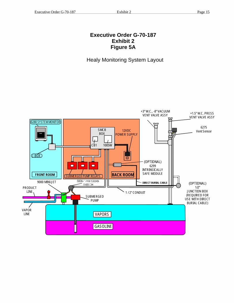
Healy Monitoring System Layout
Executive Order G-70-187Exhibit 2Figure 5A
(OPTIONAL)1/2”
JUNCTION BOX(REQUIRED FOR
USE WITH DIRECTBURIAL CABLE)
DIRECT BURIAL CABLE
(OPTIONAL)6299
INTRINSICALLYSAFE MODULE
Executive Order G-70-187 Exhibit 2 Page 15

SMCB(SYSTEM MONITOR CONTROL BOX)
Executive Order G-70-187Exhibit 2Figure 5B
System Monitor Control Box.
CB1yellow Motor L.E.D.
1005W
The SMCB is a junction box for the CB1 relay and the 1005W solid state relay. Italso acts as a junction box for the wiring cable supplied from the 6280 System Monitor, the 12VDC plug-in powersupply, field wiring from the 9800-1 Differential Pressure Switch, field wiring from the 6275 Vent Sensor Assembly,and field wiring from the Submerged Motor Relays.
The Relay, mounted in a socket, is connected to the power of the vacuum source and closes a contact thatactivates the Light on the 6280 System Monitor. It also tells the 6280 System Monitor that theproper vacuum has been achieved, within a prescribed time period, with a signal from the 9800-1 DifferentialPressure Switch.
The Solid State Relay senses the activation of product pump and transfers that signal to whichevervacuum source is being utilized at the site.
The System Monitor Control Box should be mounted near the Submerged Pump Control Relays and near a 110Vstandard electrical outlet for the 12VDC plug-in power supply. It should also be accessible to the electrical conduitsfrom the 9800-1 Differential Pressure Switch and the 6275 Vent Sensor Assembly.
209
8
20
SMCB(SYSTEM MONITOR CONTROL BOX)
WHITEBLACKBLUE
1005W RELAY
BROWNORANGEYELLOW
CB1 RELAY
2 217 1
5 73
10
Executive Order G-70-187 Exhibit 2 Pape 16
3 2 1
SAFEHAZ
GR GR
TOCOMMON
VENT SENSOR
SYSTEM GROUNDTO
NORMALLY OPEN6275 VENT SENSOR
FROM 6280SYSTEM MONITOR
FROM 6280SYSTEM MONITOR
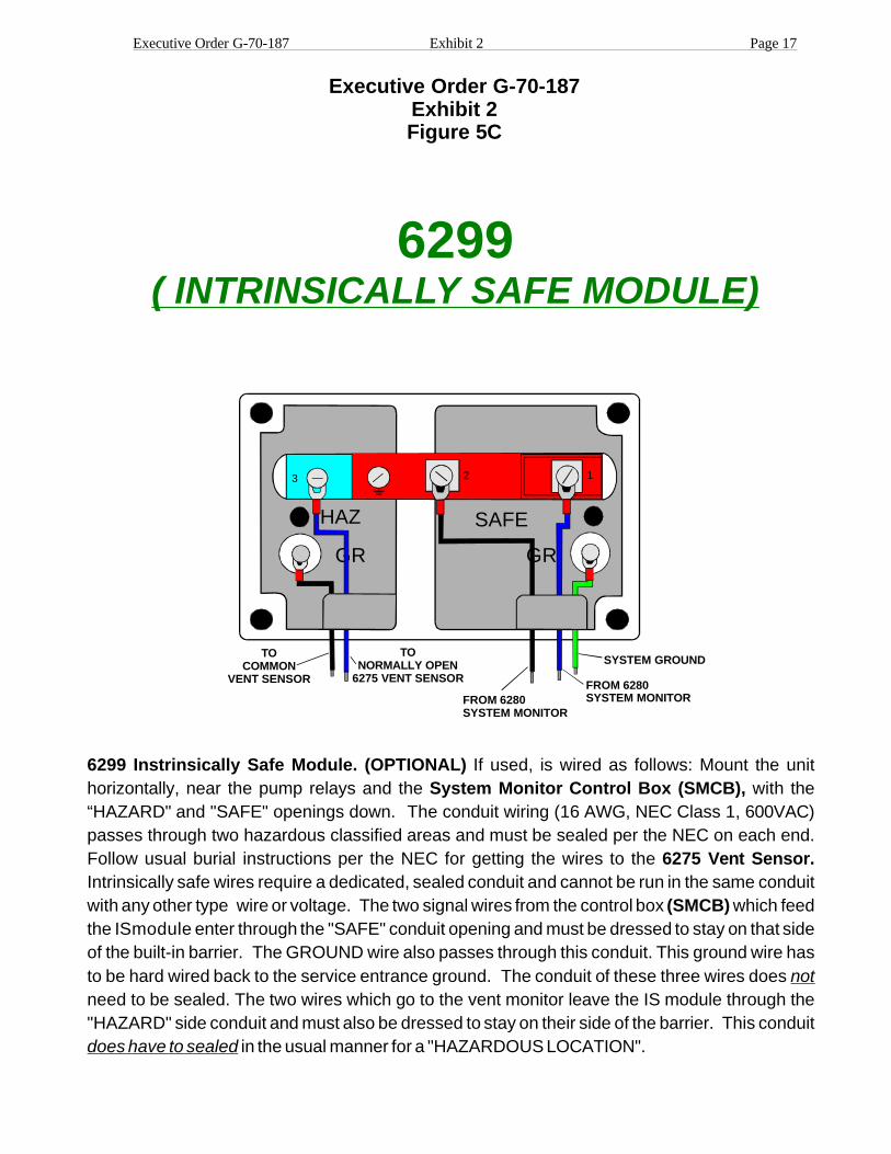
6299( INTRINSICALLY SAFE MODULE)
Executive Order G-70-187Exhibit 2Figure 5C
6299 Instrinsically Safe Module. (OPTIONAL)System Monitor Control Box (SMCB),
6275 Vent Sensor.
(SMCB)
If used, is wired as follows: Mount the unithorizontally, near the pump relays and the with the“HAZARD" and "SAFE" openings down. The conduit wiring (16 AWG, NEC Class 1, 600VAC)passes through two hazardous classified areas and must be sealed per the NEC on each end.Follow usual burial instructions per the NEC for getting the wires to theIntrinsically safe wires require a dedicated, sealed conduit and cannot be run in the same conduitwith any other type wire or voltage. The two signal wires from the control box which feedthe ISmodule enter through the "SAFE" conduit opening and must be dressed to stay on that sideof the built-in barrier. The GROUND wire also passes through this conduit. This ground wire hasto be hard wired back to the service entrance ground. The conduit of these three wires doesneed to be sealed. The two wires which go to the vent monitor leave the IS module through the"HAZARD" side conduit and must also be dressed to stay on their side of the barrier. This conduit
in the usual manner for a "HAZARDOUS LOCATION".
not
does have to sealed
Executive Order G-70-187 Exhibit 2 Page 17

Executive Order G-70-187Exhibit 2Figure 5D
9800-1(VACUUM MONITOR PRESSURE SWITCH)
9800-1 Vacuum Monitor Pressure Switch.
SMCB
The 9800-1 Vacuum Switch is mounted on thePhase II Vapor Return line from the gasoline dispensers near or on the vacuum source. Twowires (16 or 18 AWG) from the exit the building through a sealed conduit (per NEC).These wires must be 600 volt rated, Class 1 type insulation. They connect to the switchterminals common (COM.) and normally open (NO) inside the 9800-1 Vacuum Switch. SeeHealy Systems wiring diagram 9200-6308 (REV 4) sheets 1 and 2 for general layout andinstallation requirements.
HEALY
LOW SIDEHIGH SIDE
PRESSURE VACUUM SWITCHMODEL 93928
MOUNT VERTICALLYCAUTION, DISCONNECTFROM
CIRCUIT SUPPLY BEFOREOPENING, KEEPCOVER
CLOSEDWHEN INOPERATION.
P/N9431
CUSTOMARK
FOR USE O N L Y W I T H H E A L Y M O D E L 6 2 8 0 S Y S T E MMONITOR.SEE INSTALLATIONINSTRUCTIONS.
EXPLOSIONPROOFWHEN INSTALLEDWITHOUTMODEL6299I.S.MODULE.INTRINSICALLYSAFE,WHEN
INSTALLEDWITHMODEL6299I.S.MODULESUITABLEFORCLASS1,GROUPD,DIVISIONLOCATIONS.
Executive Order G-70-187 Exhibit 2 Page 18
Executive Order G-70-187 Exhibit 2 Page 19
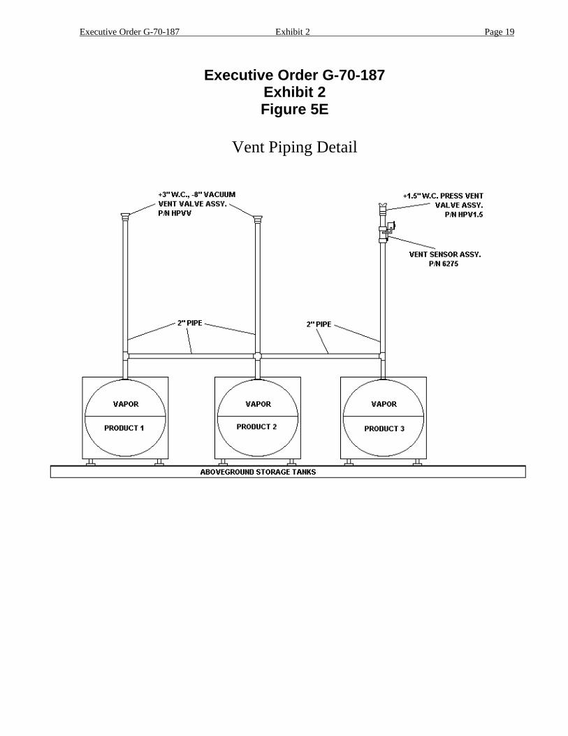
Executive Order G-70-187Exhibit 2Figure 5E
Vent Piping Detail
Executive Order G-70-187 Exhibit 2 Page 20
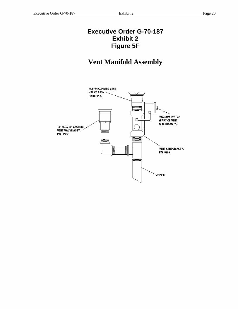
Executive Order G-70-187Exhibit 2Figure 5F
Vent Manifold Assembly
Executive Order G-70-187 Exhibit 2 Page 21
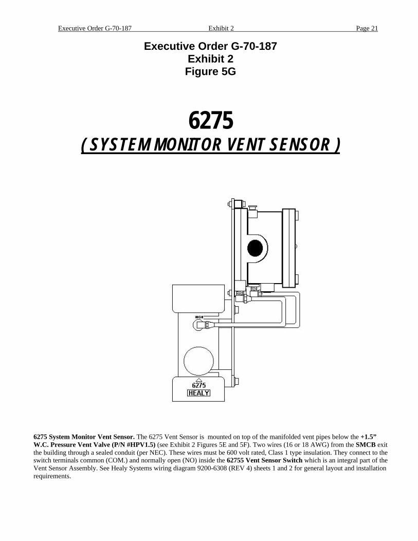
Executive Order G-70-187Exhibit 2Figure 5G
6275( SYSTEM MONITOR VENT SENSOR )
6275 System Monitor Vent Sensor. The 6275 Vent Sensor is mounted on top of the manifolded vent pipes below the +1.5”W.C. Pressure Vent Valve (P/N #HPV1.5) (see Exhibit 2 Figures 5E and 5F). Two wires (16 or 18 AWG) from the SMCB exitthe building through a sealed conduit (per NEC). These wires must be 600 volt rated, Class 1 type insulation. They connect to theswitch terminals common (COM.) and normally open (NO) inside the 62755 Vent Sensor Switch which is an integral part of theVent Sensor Assembly. See Healy Systems wiring diagram 9200-6308 (REV 4) sheets 1 and 2 for general layout and installationrequirements.
Executive Order G-70-187 Exhibit 2 Page 22
Executive Order G-70-187Exhibit 2Figure 6
MONITOR MAINTENANCE LOG SHEET
FACILITY SUPERVISOR / CONTACT NAME
( ) ADDRESS FACILITY PHONE NUMBER
CITY STATE ZIP CODE INSTALLATION DATE
Maintenance Contractor:
Phone: ( )Maintenance Performed
Date & Timeof Alarm
Type ofAlarm
Date & TimeMaintenance
Called
DateMaintenancePerformed
__________Date:
__________Time:
Vacuum:
Vent:
___________Date:
___________Time:
___________Date:
Comments:
A. Test(s) Conducted:
B. Test Results: (Attach Additional Sheets If Needed)
C. Component(s) Repaired or Replaced:
Executive Order G-70-187
Exhibit 3
STATIC PRESSURE INTEGRITY TESTABOVEGROUND STORAGE TANKS
1 Applicability
This test procedure is used to quantify the vapor tightness of vapor recovery systems installed atgasoline dispensing facilities (GDF) equipped with vacuum assist systems which requirepressure/vacuum (P/V) valves. Systems equipped with a P/V valve(s) allowed to have adesigned cracking pressure less than 2.5 inches H2O shall be bagged to eliminate any flowcontribution through the valve assembly from the test results. The valve/vent pipe connection,however, shall remain unobstructed during this test.
2 Principle
2.1 The entire vapor recovery system is pressurized with nitrogen to two (2.0) inches H2O. Thesystem pressure is then allowed to decay and the pressure after five (5) minutes is comparedwith an allowable value. The minimum allowable five-minute final pressure is based on thesystem ullage and pressure decay equations. For the purpose of compliance determination, thistest shall be conducted after installation of all Phase I and Phase II components, including P/Vvalves, and all back-filling and paving has been completed.
2.2 For GDF equipped with a coaxial Phase I system, this test shall be conducted at a Phase II vaporriser. For GDF which utilize a two-point Phase I system, this test may be conducted at either(1) a Phase II vapor riser, (2) a Phase I vapor coupler or (3) an unused storage tank portprovided that the vapor coupler poppet valve is leak free as determined by the method set forthin Section 6.7. If the vapor poppet valve is leak free, it is recommended that this test beconducted at the Phase I vapor coupler or an unused storage tank port.
3 Range
3.1 If mechanical pressure gauges are employed, the full-scale range of the pressure gauges shall be0-2.0, 0-1.0, and 0-0.50 inches H2O column. Maximum incremental graduations of the pressuregauge shall be 0.05 inches H2O and the minimum accuracy of the gauge shall be three percent offull scale. The minimum diameter of the pressure gauge face shall be 4 inches. A 0-2 inchesH2O inclined manometer, or equivalent, may be used provided that the minor scale divisions donot exceed 0.02 inches H2O.
3.2 If an electronic pressure measuring device is used, the full-scale range of the device shall notexceed 0-10 inches H2O with a minimum accuracy of 0.5 percent of full-scale. A 0-20 inchesH2O device may be used, provided the equivalent accuracy is not less than 0.25 percent of fullscale.
3.3 The minimum and maximum nitrogen feed-rates, into the system, shall be one (1) and five (5)CFM, respectively.

Executive Order G-70-187 Exhibit 3 Page 2
4 Interferences
4.1 Introduction of nitrogen into the system at flowrates exceeding five (5) CFM may bias theresults of the test toward non-compliance. Only gaseous nitrogen shall be used to conduct thistest. Air, liquefied nitrogen, helium, or any gas other than nitrogen shall not be used for thistest procedure.
4.2 The results of this Static Pressure Integrity Test shall not be used to verify compliance if an Airto Liquid Volumetric Ratio Test (Test Procedure TP-201.5 or equivalent) was conducted withinthe 24 hours prior to this test.
Figure 3-1
"T" Connector Assembly
Executive Order G-70-187 Exhibit 3 Page 3
5 Apparatus
5.1 Nitrogen. Use commercial grade nitrogen in a high-pressure cylinder, equipped with a two-stage pressure regulator and a one-psig pressure relief valve.
5.2 Pressure Measuring Device. Use 0-2.0, 0-1.0, and 0-0.50 inches H2O pressure gaugesconnected in parallel, a 0-2 inches H2O manometer, or an electronic pressure measuring deviceto monitor the pressure decay in the vapor recovery system. The pressure measuring deviceshall, at a minimum, be readable to the nearest 0.05 inches H2O.
5.3 "T" Connector Assembly. See Figure 3-1 for example.
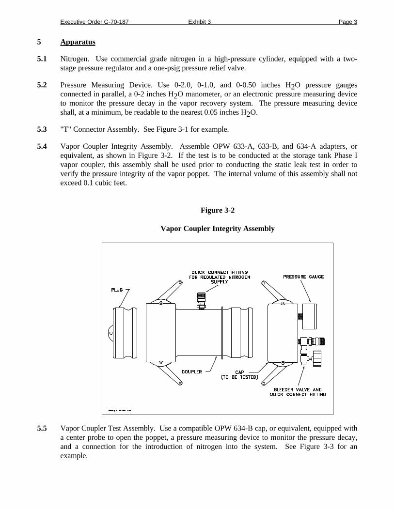
5.4 Vapor Coupler Integrity Assembly. Assemble OPW 633-A, 633-B, and 634-A adapters, orequivalent, as shown in Figure 3-2. If the test is to be conducted at the storage tank Phase Ivapor coupler, this assembly shall be used prior to conducting the static leak test in order toverify the pressure integrity of the vapor poppet. The internal volume of this assembly shall notexceed 0.1 cubic feet.
Figure 3-2
Vapor Coupler Integrity Assembly
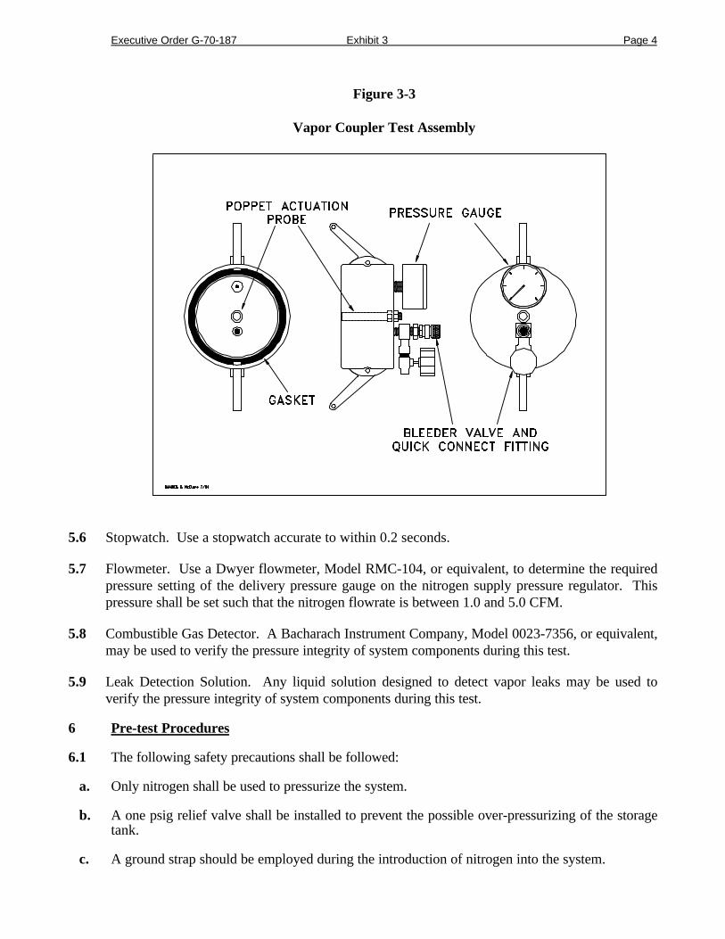
5.5 Vapor Coupler Test Assembly. Use a compatible OPW 634-B cap, or equivalent, equipped witha center probe to open the poppet, a pressure measuring device to monitor the pressure decay,and a connection for the introduction of nitrogen into the system. See Figure 3-3 for anexample.
Executive Order G-70-187 Exhibit 3 Page 4
Figure 3-3
Vapor Coupler Test Assembly
5.6 Stopwatch. Use a stopwatch accurate to within 0.2 seconds.
5.7 Flowmeter. Use a Dwyer flowmeter, Model RMC-104, or equivalent, to determine the requiredpressure setting of the delivery pressure gauge on the nitrogen supply pressure regulator. Thispressure shall be set such that the nitrogen flowrate is between 1.0 and 5.0 CFM.
5.8 Combustible Gas Detector. A Bacharach Instrument Company, Model 0023-7356, or equivalent,may be used to verify the pressure integrity of system components during this test.
5.9 Leak Detection Solution. Any liquid solution designed to detect vapor leaks may be used toverify the pressure integrity of system components during this test.
6 Pre-test Procedures
6.1 The following safety precautions shall be followed:
a. Only nitrogen shall be used to pressurize the system.
b. A one psig relief valve shall be installed to prevent the possible over-pressurizing of the storagetank.
c. A ground strap should be employed during the introduction of nitrogen into the system.

Executive Order G-70-187 Exhibit 3 Page 5
6.2 Failure to adhere to any or all of the following time and activity restrictions shall invalidate thetest results:
a. There shall be no Phase I bulk product deliveries into or out of the storage tank(s) within thethree (3) hours prior to the test or during performance of this test procedure.
b. There shall be no product dispensing within thirty (30) minutes prior to the test or duringperformance of this test procedure.
c. Upon commencement of the thirty minute “no dispensing” portion of this procedure, theheadspace pressure in the tank shall be measured. If the pressure exceeds 0.50 inches H2O, thepressure shall be carefully relieved in accordance with all applicable safety requirements. Afterthe thirty minute “no dispensing” portion of this procedure, and prior to introduction ofnitrogen, the headspace pressure shall again be lowered, if necessary, to less than 0.50 inchesH2O.
d. There shall be no Air to Liquid Volumetric Ratio Test (Test Procedure TP-201.5) conductedwithin the twenty-four (24) hour period immediately prior to this test.
6.3 Measure the gallons of gasoline present in each aboveground storage tank and determine theactual capacity of each storage tank from facility records. Calculate the ullage space for eachtank by subtracting the gasoline gallonage present from the actual tank capacity. The minimumullage during the test shall be 25 percent of the tank capacity or 500 gallons for tank sizesgreater than 1,000 gallons and 300 gallons for tank sizes equal to or less than 1,000 gallons,whichever is greater. The total ullage shall not exceed 25,000 gallons. These values areexclusive of all vapor piping volumes.
6.4 For top mounted two-point Phase I systems, this test shall be conducted with the dust capremoved from the vapor coupler if the test is conducted by pressurizing the system at the PhaseII vapor riser or an unused storage tank port. For remote vapor return systems, this test shall beconducted at the Phase II vapor riser or an unused storage tank port with all valves and caps onthe vapor return line in place.
6.5 For coaxial Phase I systems, this test shall be conducted by pressurizing the system at the PhaseII vapor riser or an unused storage tank port with the dust cap removed from the Phase Icoupler. This is necessary to insure the vapor tightness of the Phase I vapor poppet.
6.6 If the Phase I spill containment box (when installed) is equipped with a drain valve, the valveassembly may be cleaned and lubricated prior to the test. This test shall, however, be conductedwith the drain valve installed and the manhole cover removed
6.7 If the test is to be conducted at a Phase II vapor riser, disconnect the dispenser end of one vaporrecovery hose and install the "T" connector assembly (see Figure 3-1). Connect the nitrogen gassupply (do not use air) and the pressure measuring device to the "T" connector. For those PhaseII systems utilizing a dispenser mounted remote vapor check valve, the “T” connector assemblyshall be installed on the vapor riser side of the check valve.
6.8 If this test is to be conducted at the Phase I vapor coupler on a two-point Phase I system, theprocedures set forth in subsections 6.7.1 and 6.7.2 shall be successfully completed prior totesting. The static pressure integrity test shall not be conducted at the Phase I coupler atfacilities equipped with coaxial Phase I systems.
a. Connect the Vapor Coupler Integrity Assembly to the Phase I vapor coupler. Connect theVapor Coupler Test Assembly. Connect the nitrogen supply to the assembly and carefullypressurize the internal volume of the assembly to two (2.0) inches H2O. Start the stopwatch.Record the final pressure after one minute.

Executive Order G-70-187 Exhibit 3 Page 6
b. If the pressure after one minute is less than 0.25 inches H2O, the leak rate through the Phase Ivapor poppet precludes conducting the static leak test at this location. If the pressure after oneminute is greater than or equal to 0.25 inches H2O, the static leak test may be conducted at thislocation. This criteria assures a maximum leak rate through the Phase I vapor poppet of lessthan 0.0004 cubic feet per minute.
c. Disconnect the Vapor Coupler Integrity Assembly from the Phase I vapor coupler. If therequirements of subsection 6.7.2 were met, connect the Vapor Coupler Test Assembly to thePhase I vapor coupler.
d. As an alternate to the requirements of subsections 6.7.1 through 6.7.3, leak detection solutionmay be used to verify the absence of vapor leaks through the Phase I vapor poppet on two-pointPhase I systems. This alternative leak check is valid only for two-point Phase I systems in whichtanks are manifolded. The manifold may be at the vent pipes. Pressurize the system to two (2)inches H2O and use the leak detection solution to verify a zero leak (absence of bubbles)condition at one of the vapor poppets on the Phase I system.
6.9 All pressure measuring device(s) shall be bench calibrated using either a reference gauge orincline manometer. Calibration shall be performed at 20, 50, and 80 percent of full scale.Accuracy shall be within two percent at each of these calibration points. Calibrations shall beconducted on a frequency not to exceed 90 days.
6.10 Use the flowmeter to determine the nitrogen regulator delivery pressures which correspond tonitrogen flowrates of 1.0 and 5.0 CFM. These pressures define the allowable range of deliverypressures acceptable for this test procedure. Also record which regulator delivery pressuresetting, and the corresponding nitrogen flowrate that will be used during the test. As analternative, the flowmeter may be connected, in-line between the nitrogen supply regulator andVapor Coupler Test Assembly, during the test.
6.11 Use Equation 9.2 to calculate the approximate time required to pressurize the system ullage tothe initial starting pressure of two (2.0) inches H2O. This will allow the tester to minimize thequantity of nitrogen introduced into those systems which cannot comply with the static leakstandards.
6.12 Attach the Vapor Coupler Test assembly to the Phase I poppet or the "T" connector assembly tothe Phase II vapor riser. Read the initial pressure of the storage tank and aboveground piping.If the initial pressure is greater than 0.5 inches H2O, carefully bleed off the pressure, inaccordance with all applicable safety procedures, in the storage tank and aboveground piping toless than 0.5 inches H2O column.
7 Testing
7.1 Open the nitrogen gas supply valve and set the regulator delivery pressure within the allowablerange determined in Section 6.9, and start the stopwatch. Pressurize the vapor system (orsubsystem for individual vapor return line systems) to at least 2.2 inches H2O initial pressure.It is critical to maintain the nitrogen flow until the pressure stabilizes, indicating temperature andvapor pressure stabilization in the tanks. Check the test equipment using leak detecting solutionor a combustible gas detector to verify that all test equipment is leak tight.
a. If the time required to achieve the initial pressure of two (2.00) inches H2O exceeds twice thetime derived from Equation 9.2, stop the test and use a liquid leak detector, or a combustible gasdetector, to find the leak(s) in the system. Failure to achieve the initial starting pressure withintwice the time derived from Equation 9.2 demonstrates the inability of the system to meet theperformance criteria. Repair or replace the faulty component(s) and restart the test pursuant toSection 7.1.
Executive Order G-70-187 Exhibit 3 Page 7
7.2 Close and disconnect the nitrogen supply. Start the stopwatch when the pressure has decreasedto the initial starting pressure of two (2.0) inches H2O.
7.3 At one-minute intervals during the test, record the system pressure. After five minutes, recordthe final system pressure. See Table 3-I (or Equation 9.1) to determine the acceptability of thefinal system static pressure results. For intermediate values of ullage in Tables 3-I, linearinterpolation may be employed.
7.4 If the system failed to meet the criteria set forth in Table 3-I (or Equation 9-2), re-pressurize thesystem and check all accessible vapor connections using leak detector solution or a combustiblegas detector. If vapor leaks in the system are encountered, repair or replace the defectivecomponent and repeat the test. Potential sources of leaks include nozzle check valves,pressure/vacuum relief valves, containment box drain valve assemblies, and plumbingconnections at the risers.
7.5 After the remaining system pressure has been relieved, remove the "T" connector assembly andreconnect the vapor recovery hose, if applicable.
7.6 If the vapor recovery system utilizes individual vapor return lines, repeat the leak test for eachgasoline grade. Avoid leaving any vapor return line open longer than is necessary to install orremove the "T" connector assembly.
7.7 If the containment box has a cover-actuated drain valve, repeat the test with the cover in place.In these cases clearly specify, on Form 3-1, which results represent the pressure integrity withand without the cover in place.
8 Post-Test Procedures
Use Table 3-I, or Equation 9.1 to determine the compliance status of the facility by comparingthe final five-minute pressure with the minimum allowable final pressure.
9 Calculations
Executive Order G-70-187 Exhibit 3 Page 8
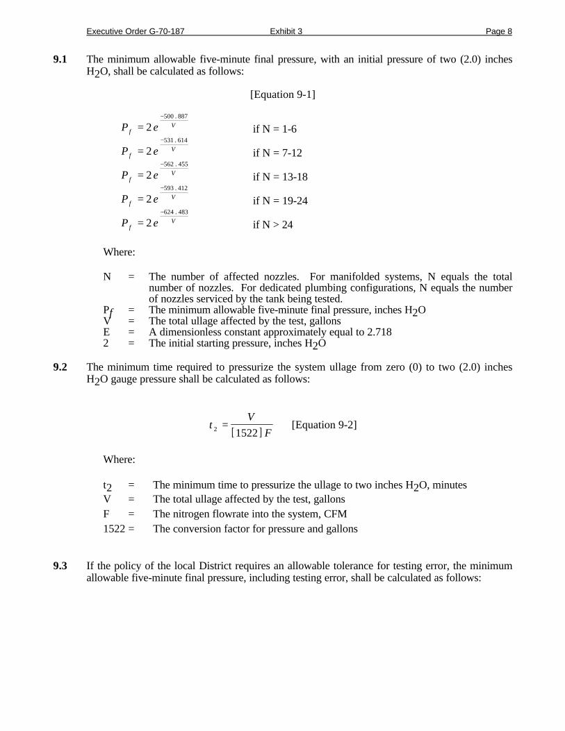
9.1 The minimum allowable five-minute final pressure, with an initial pressure of two (2.0) inchesH2O, shall be calculated as follows:
[Equation 9-1]
P efV=
−
2500 887.
if N = 1-6
P efV=
−
2531 614.
if N = 7-12
P efV=
−
2562 455.
if N = 13-18
P efV=
−
2593 412.
if N = 19-24
P efV=
−
2624 483.
if N > 24
Where:
N = The number of affected nozzles. For manifolded systems, N equals the totalnumber of nozzles. For dedicated plumbing configurations, N equals the numberof nozzles serviced by the tank being tested.
Pf = The minimum allowable five-minute final pressure, inches H2OV = The total ullage affected by the test, gallonsE = A dimensionless constant approximately equal to 2.7182 = The initial starting pressure, inches H2O
9.2 The minimum time required to pressurize the system ullage from zero (0) to two (2.0) inchesH2O gauge pressure shall be calculated as follows:
[ ]t
V
F2 1522= [Equation 9-2]
Where:
t2 = The minimum time to pressurize the ullage to two inches H2O, minutesV = The total ullage affected by the test, gallonsF = The nitrogen flowrate into the system, CFM1522 = The conversion factor for pressure and gallons
9.3 If the policy of the local District requires an allowable tolerance for testing error, the minimumallowable five-minute final pressure, including testing error, shall be calculated as follows:

Executive Order G-70-187 Exhibit 3 Page 9
( )[ ]PE
Pf E f− = − +
− +2 1
100408 9 406 9. . [Equation 9-3]
Where:
Pf-E = The minimum allowable five-minute final pressure including allowable testing error,inches H2O
E = The allowable testing error, percentPf = The minimum allowable five-minute final pressure calculated in Equations 9-1 or 9-2,
inches H2O2 = The initial starting pressure, inches H2O408.9 = Atmospheric pressure plus the initial starting pressure, inches H2O406.9 = Atmospheric pressure, inches H2O
10 Reporting
The calculated ullage and system pressures for each five-minute vapor recovery system test shallbe reported as shown in Form 3-1. Be sure to include the Phase I system type (two-point orcoaxial), the Phase II system type, whether the system is manifolded, and the one-minutepressures during the test.
Executive Order G-70-187 Exhibit 3 Page 10
Executive Order G-70-187
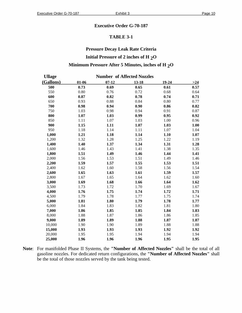
TABLE 3-1
Pressure Decay Leak Rate Criteria
Initial Pressure of 2 inches of H 2O
Minimum Pressure After 5 Minutes, inches of H 2O
Ullage Number of Affected Nozzles(Gallons) 01-06 07-12 13-18 19-24 >24
500 0.73 0.69 0.65 0.61 0.57550 0.80 0.76 0.72 0.68 0.64600 0.87 0.82 0.78 0.74 0.71650 0.93 0.88 0.84 0.80 0.77700 0.98 0.94 0.90 0.86 0.82750 1.03 0.98 0.94 0.91 0.87800 1.07 1.03 0.99 0.95 0.92850 1.11 1.07 1.03 1.00 0.96900 1.15 1.11 1.07 1.03 1.00950 1.18 1.14 1.11 1.07 1.04
1,000 1.21 1.18 1.14 1.10 1.071,200 1.32 1.28 1.25 1.22 1.191,400 1.40 1.37 1.34 1.31 1.281,600 1.46 1.43 1.41 1.38 1.351,800 1.51 1.49 1.46 1.44 1.412,000 1.56 1.53 1.51 1.49 1.462,200 1.59 1.57 1.55 1.53 1.512,400 1.62 1.60 1.58 1.56 1.542,600 1.65 1.63 1.61 1.59 1.572,800 1.67 1.65 1.64 1.62 1.603,000 1.69 1.68 1.66 1.64 1.623,500 1.73 1.72 1.70 1.69 1.674,000 1.76 1.75 1.74 1.72 1.714,500 1.79 1.78 1.77 1.75 1.745,000 1.81 1.80 1.79 1.78 1.776,000 1.84 1.83 1.82 1.81 1.807,000 1.86 1.85 1.85 1.84 1.838,000 1.88 1.87 1.86 1.86 1.859,000 1.89 1.89 1.88 1.87 1.8710,000 1.90 1.90 1.89 1.88 1.8815,000 1.93 1.93 1.93 1.92 1.9220,000 1.95 1.95 1.94 1.94 1.9425,000 1.96 1.96 1.96 1.95 1.95
Note: For manifolded Phase II Systems, the "Number of Affected Nozzles" shall be the total of allgasoline nozzles. For dedicated return configurations, the "Number of Affected Nozzles" shallbe the total of those nozzles served by the tank being tested.
Executive Order G-70-187 Exhibit 3 Page 11
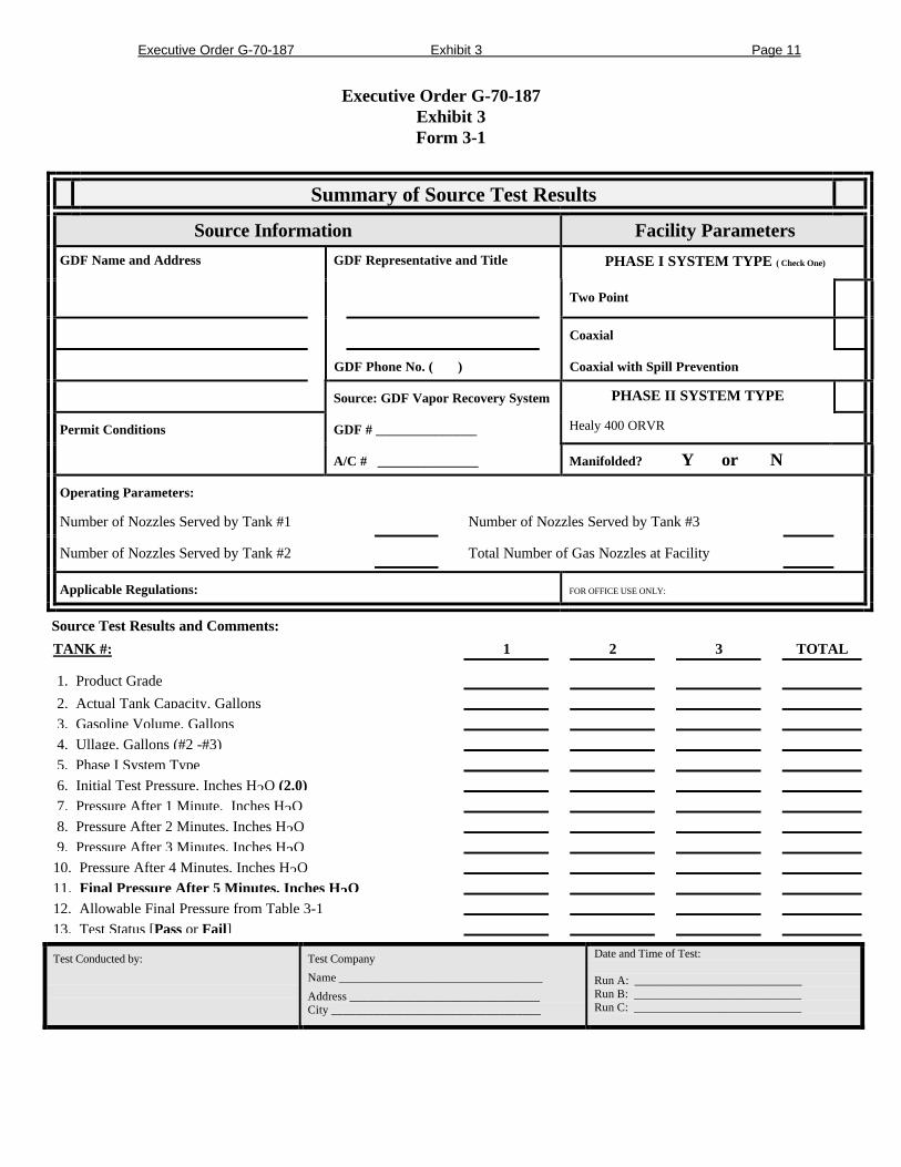
Executive Order G-70-187Exhibit 3Form 3-1
Summary of Source Test Results
Source Information Facility Parameters
GDF Name and Address GDF Representative and Title PHASE I SYSTEM TYPE ( Check One)
Two Point
Coaxial
GDF Phone No. ( ) Coaxial with Spill Prevention
Source: GDF Vapor Recovery System PHASE II SYSTEM TYPE
Permit Conditions GDF # _______________ Healy 400 ORVR
A/C # _______________ Manifolded? Y or N
Operating Parameters:
Number of Nozzles Served by Tank #1 Number of Nozzles Served by Tank #3
Number of Nozzles Served by Tank #2 Total Number of Gas Nozzles at Facility
Applicable Regulations: FOR OFFICE USE ONLY:
Source Test Results and Comments:
TANK #: 1 2 3 TOTAL
1. Product Grade
2. Actual Tank Capacity, Gallons 3. Gasoline Volume, Gallons 4. Ullage, Gallons (#2 -#3) 5. Phase I System Type 6. Initial Test Pressure, Inches H2O (2.0) 7. Pressure After 1 Minute, Inches H2O 8. Pressure After 2 Minutes, Inches H2O 9. Pressure After 3 Minutes, Inches H2O10. Pressure After 4 Minutes, Inches H2O11. Final Pressure After 5 Minutes, Inches H2O12. Allowable Final Pressure from Table 3-113. Test Status [Pass or Fail]
Test Conducted by: Test Company
Name __________________________________
Address ________________________________City ___________________________________
Date and Time of Test:
Run A: ____________________________Run B: ____________________________Run C: ____________________________
Executive Order G-70-187
Exhibit 4
Vapor Return Line Vacuum Integrity Test for theHealy Model 400 ORVR System
1 Applicability
This test procedure is used to verify the vapor tightness of the portion of the Healy systemwhich is subjected to relatively high levels of vacuum in the vapor return lines. A defectivevapor valve, or any other defect which compromises the integrity of the vapor lines from thenozzle to the central vacuum unit, may cause the ingestion of large amounts of air. Excess air inthe storage tanks will cause significant vent emissions when the pressure exceeds the pressuresetting of the P/V valve. Ingested air will also cause the evaporation of gasoline in the storagetanks and may result in observable product shrinkage.
Note: This test is required in addition to, and not as an alternative for, the static pressure decaytest in Exhibit 3.
2 Principle
The vapor lines from the nozzle to the central vacuum unit are isolated from the abovegroundstorage tanks by closing the vapor and siphon line ball valves after activating the central vacuumunit. The unit is turned off and the vacuum is allowed to decay. The value is compared with anallowable value.
3 Range
3.1 If mechanical pressure gauges are employed, the full-scale range of the pressure gauges shall bezero to 100 inches water column (0 - 100" wc), to be sensed as vacuum. Maximum incrementalgraduations of the pressure gauge shall be 2 inches wc and the minimum accuracy of the gaugeshall be three percent of full scale. The minimum diameter of the pressure gauge face shall befour (4) inches.
3.2 If an electronic pressure measuring device is used, the full scale range of the device shall notexceed zero to 200 inches water column (0 - 200" wc) with a minimum accuracy of 0.5 percentof full scale.
4 Interferences
Any attempts to dispense product during the test will open the lines being tested and invalidatethe results.
5 Apparatus
5.1 Pressure Measuring Device. Use a pressure gauge, or an electronic pressure measuring device,set up to measure vacuum, to monitor the decay of the vacuum level in the vapor return lines.The pressure measuring device shall, at a minimum, be readable to 2 inches water column.
5.2 Stopwatch. Use a stopwatch accurate to within 0.2 seconds.
6 Pre-Test Procedures
6.1 There shall be no product dispensing during the test.
6.2 All pressure measuring device(s) shall be bench calibrated using either a reference gauge orincline manometer. Calibration shall be performed at 20, 50 and 80 percent of full scale.Accuracy shall be within two percent at each of these calibration points. Calibrations shall beconducted on a frequency not to exceed 90 days.
Executive Order G-70-187 Exhibit 4 Page 2
6.3 Remove the tap or quick-connect cap and install the pressure measuring device. The deviceshall be installed in the portion of the vapor line to be isolated.
7 Testing
7.1 Turn on the central vacuum unit (CVU) by activating a dispenser. The CVU is turned off byreplacing the nozzle on the dispenser. Alternatively, the test may be conducted immediatelyfollowing product dispensing.
7.2 Observe the vacuum level on the pressure measuring device. When the vacuum level is stable,or at the end of the dispensing operation, close the vapor and siphon line ball valves to isolatethe vapor lines from the storage tanks (refer to Exhibit 2,Figures 2A thru 2D and Figure 3 forthe location of the ball valves) and turn off the CVU by replacing the nozzle on the dispenser. Ifa stable vacuum level is not observed after one minute of CVU operation, or if the stablevacuum level is less than that indicated in Exhibit 2 as within the normal vacuum level for theCVU installed, turn off the CVU and check for problems before proceeding with the test.
7.3 Note the initial vacuum level and start the stopwatch. Record the vacuum level at one minuteintervals. After five minutes, record the final vacuum level.
7.4 Calculate the difference between the final vacuum level and the initial vacuum level to obtain theobserved change in vacuum. Note this value as the "measured DP". Estimate the total lengthof 2 inch diameter vapor return pipe from the dispensers to the CVU. Use this value to obtainthe "calculated DP" in equation 4.1. If the "measured DP" is greater than the value obtained byequation 4-1, then a vapor leak is evident and the system has failed. If the vacuum level doesnot decay more than the allowable level, proceed to Section 8.
Equation 4.1
DP = 800/N
Where:
N = The approximate length of 2 inch vapor return pipe from the dispensers to thecentral vacuum unit to the nearest 20 feet .
DP = The observed change in vacuum level in inches of water column during a fiveminute observation period.
Note: If the station contains 3 inch vapor return pipes, multiply the answer in Equation 4.1 by0.5. This equation is based on an allowable leak rate of 0.08 gallons per minute.
7.5 If the system has failed to meet the criteria set forth in Section 7.4, repair and replace defectivecomponents as necessary and repeat the test. Defective nozzles or other components may bediagnosed by bagging with bags containing air and observing collapse of the bags, or byotherwise isolating suspected components.
Note: This is only for diagnostic purposes; the test shall not be conducted with any bagged orisolated components.
7.6 If the system contains more than one CVU, repeat for each CVU and associated piping.
8 Post-Test Procedures
8.1 Remove the pressure measuring device and plug or cap to ensure that the connection point isleak tight.
8.2 Open the valves which were closed to isolate the vapor return lines.

Executive Order G-70-187 Exhibit 4 Page 3
9 Reporting
The observed initial, interim and final vacuum levels observed, the type of pressure measuringdevice (including range and accuracy and date of last calibration), the number of nozzlesassociated with the CVU and the measured DP shall be reported.
Executive Order G-70-187
Exhibit 5Fillneck Vapor Pressure Regulation Fueling Test
1 ApplicabilityThis test procedure is used to verify proper operation of the nozzle boot pressure regulationunique to the Healy Model 400 ORVR nozzle.
2 Principle
The nozzle vapor pressure regulation is verified during refueling into a tight simulated vehiclefuel tank with saturated vapors (Procedure 1) or into an actual non-ORVR equipped vehicle(Procedure 2). Pressure readings are taken with a mechanical gauge during a fueling of at least5 gallons, excluding the first two gallons and last one gallon dispensed in order to eliminate theinterferences due to vapor growth or contraction. A vacuum which exceeds ½ inches wc, or apressure which exceeds ¼ inches wc, except during the excluded beginning and ending gallons,indicates a defective nozzle.
3 Interferences
Vacuum or pressure levels outside of the specified range may occur during the beginning orend of the refueling operation when properly functioning equipment is affected by thefollowing conditions: (1) gasoline dispensed into a vehicle fuel tank which is significantlywarmer than the dispensed fuel may cause a vacuum of several inches water column; and,conversely, (2) gasoline dispensed into a vehicle tank which is significantly cooler than thedispensed fuel may temporarily cause a pressure greater than ¼ inches water column. Theeffect of the temperature differential will be most pronounced at the beginning of the fuelingoperation and tends to gradually disappear toward the end of the fueling operation as fuel andvapor temperatures in the vehicle fuel tank equalize.
4 Apparatus
Mechanical Pressure Gauge - the full scale range of the gauge shall be 1 inch water columnpressure to 1 inch water column vacuum (-1.0” wc – +1.0” wc). Maximum incrementalgraduations of the pressure gauge shall be 0.25 inches wc and the minimum accuracy of thegauge shall be three percent (3%) of full scale. The minimum diameter of the pressure gaugeshall be four inches.
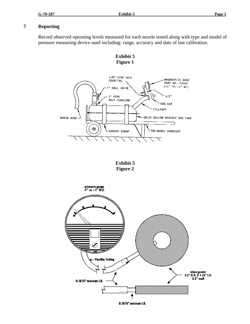
4.1 Procedure 1. Use a gauge mounted on the test tank fillneck to measure vapor pressure duringfueling of a simulated fuel tank (see Figure 1). Any test tank as approved in Air ResourcesBoard, Source Test Methods, Volume 2, TP-201.5, “Determination (by Volume Meter) of Airto Liquid Volume Ratio of Vapor Recovery Systems of Dispensing Facilities” may be used inlieu of the setup shown in Figure 1.
4.2 Procedure 2. Use a gauge mounted on a stand and placed level on the vehicle during fuelingof actual vehicles (see Figure 2).
G-70-187 Exhibit 5 Page 2
4.3 All pressure measuring device(s) shall be bench calibrated using either a reference gauge or aninclined manometer. Calibration shall be performed at 20, 50 and 80 percent of full scale.Accuracy shall be within two percent (2%) at each calibration point. Instrument Calibrationsshall be conducted and a certification report filed periodically every 90 days (or less).
5 Pre-Test Procedures
Verify that the system vacuum source is operating in the 65” to 85” WC operating range. Notears or holes are allowed in or on the nozzle boot or face seal.
Ensure that the high vacuum vapor return lines are tight (see Exhibit 4).
5.1 Procedure 1 – simulated vehicle fuel tank (Figure 1).
a. Position test tank next to dispenser nozzle being tested.
b. Dispense 1-2 gallons of gasoline into test tank.
c. Remove nozzle and replace fill cap.
d. Roll tank back and forth vigorously for thirty seconds to splash saturate the vapor head space inthe tank.
5.2 Procedure 2 – Torus Pressure Test with actual vehicle (Figure 2).
a. Place the gauge assembly on the vehicle in a level position.
6 Testing
6.1 Procedure 1
a. Remove the fillpipe cap and insert nozzle, making a seal between the nozzle boot and the testtank fillpipe opening. Dispense gasoline (minimum 5 gallons).
b. Observe pressure gauge during fueling.
c. Repeat test for additional nozzles. Drain test tank as necessary.
6.2 Procedure 2
a. Remove the fillpipe cap and position the torus centered over the vehicle fillpipe. Insert nozzle,making a seal between the nozzle boot and the torus and between the torus and fillpipe.Dispense gasoline (minimum 5 gallons).
b. Observe pressure gauge during fueling.
c. Repeat test for additional nozzles.
G-70-187 Exhibit 5 Page 3
7 Reporting
Record observed operating levels measured for each nozzle tested along with type and model ofpressure measuring device used including: range, accuracy and date of last calibration.
Exhibit 5Figure 1
Exhibit 5Figure 2

EXECUTIVE ORDER G-70-187
EXHIBIT 6
TEN GALLON PER MINUTE LIMITATIONCOMPLIANCE VERIFICATION PROCEDURE
Compliance with the 10 gallon per minute flowrate limitation shall be determined with thefollowing methodology. It is recommended that the maximum dispensing rate througheach nozzle/hose assembly be verified.
1) The facility uses identical models of hoses, nozzles, and breakaways:
Dispense gas into a vehicle or approved container. Dispensing shall be conducted in the“hand-held, wide-open” mode. Using a stopwatch accurate to at least 0.2 seconds, begintiming the dispensing rate after at least one gallon has been dispensed. This one gallonbuffer is necessary due to the “slow-start” nature of some dispensers. Determine the timerequired to dispense 2, 3, 4, or 5 gallons of gasoline. The facility shall be deemed incompliance with the 10 gallon per minute limitations if the elapsed time meets, or exceeds,the times shown in Table 1. If the dispensing rate exceeds the allowable limit, a CARB-certified flow limiting device shall be installed.
2) The facility uses different models of hoses, nozzles, or breakaways
Due to potential differences in pressure drops through the various components, each ofthe nozzle/hose assemblies shall be tested for maximum dispensing rates. Using the samecriteria as above, determine the maximum dispensing rate through each nozzle/hoseassembly. If the maximum dispensing rate exceeds the 10 gpm limit, a CARB-certifiedflow limiting device shall be installed.
Table 1Verification of 10 gpm
Product Dispensed, gallons Minimum Allowable Time, seconds
2.0 11.83.0 17.74.0 23.65.0 29.5
Note: The times have been corrected to allow for the accuracy of the measurement.